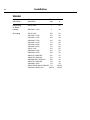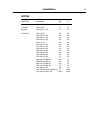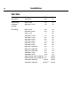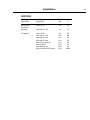
1
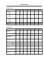
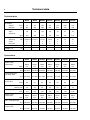
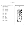
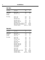
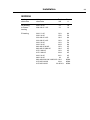
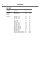
Installation manual W465H, W475H/S, W485S, W4105H/S, W4130H/S, W4180H/S, W4240H, W4250S, W4300H, W4330S Clarus Control From machine No. W475N/S, W485N/S, W4105N/S, W4130N/S W4180N/S W4250N/S W4330N/S 00521/40218300650/10738400725/10549400795/102510- 438 9037-41/EN 09.48 Contents Contents Safety Precautions......................................................................................5 Technical data.............................................................................................7 Installation H-model..................................................................................13 Transportation and unpacking, W465H, W475H, W4105H..................13 Transportation and unpacking, W4130H-W4300H..............................14 Siting and floor.....................................................................................15 Mechanical installation.........................................................................16 Installation S-model..................................................................................17 Siting.....................................................................................................17 Floor......................................................................................................17 Casting a plinth.....................................................................................18 Installation on an excisting floor or foundation....................................20 Installation on vinyl floor coverings......................................................21 Installation, ships, oil-rigs etc...............................................................22 Welding a foundation............................................................................23 Installing the machine...........................................................................24 Water connections................................................................................25 Drain connection..................................................................................27 Steam connection................................................................................28 Connection of external liquid supplies.................................................29 Electrical installation.............................................................................31 How to convert heating elements from 3AC to 1AC............................40 Function checks........................................................................................47 The manufacturer reserves the right to make changes to design and component specifications. 3 Safety Precautions Safety Precautions The machine is only intended for water-wash use. Do not allow minors to use the machine. Do not hose down the machine with water. The machine's door lock must under no circumstances be bypassed. If the machine develops a fault, this must be reported to the person in charge as soon as possible. This is important both for your safety and that of others. The machine is not intended to be used by people (including minors) with reduced physical or mental capacity or lack of experience and knowledge. Such people must be instructed in the use of the machine by a person who has responsibility for their safety. Minors must be supervised to ensure that they do not play with the machine. All external equipment which is connected to the machine must be CE/EMC-approved and connected using an approved shielded cable. In order to prevent damage to the electronics (and other parts) that may occur as the result of condensation, the machine should be placed in room temperature for 24 hours before being used for the first time. 5 Technical data 7 Technical data W465H Innerdrum volume diameter litres mm Drum speed wash extraction rpm 65 520 75 520 105 595 130 650 180 725 240 795 300 795 49 49 49 49 44 42 42 1100 1100 1025 980 930 890 820 5.4/7.5 x x 7.5/10 x x 13 x x 18 x x 23 x x 23 x x Heating electricity kW 5.4/7.5 steam x hot water x G-factor Weight, net W475H W4105H W4130H W4180H W4240H W4300H 350 350 350 350 350 350 300 kg 144 159 201 267 350 400 509 Connections W465H Water valves connection BSP DN20 3/4" W475H DN20 3/4" W4105H W4130H W4180H W4240H W4300H DN20 3/4" DN20 3/4" DN20 3/4" DN20 3/4" DN20 3/4" Rec. water pressure kPa 200-600 200-600 200-600 200-600 200-600 200-600 200-600 Functioning limits for water valve 50-1000 50-1000 50-1000 50-1000 50-1000 50-1000 Capacity at 300 kPa kPa 50-1000 l/min 20 Drain valve outer Ø mm 50/75 20 20 20 30 60 60 50/75 50/75 75 75 75 75 Draining capacity l/min 170 170 170 170 170 170 170 Steam valve connection BSP DN15 1/2" DN15 1/2" DN15 1/2" DN15 1/2" DN15 1/2" DN15 1/2" DN15 1/2" Rec. steam pressure kPa 300-600 300-600 300-600 300-600 300-600 300-600 300-600 Functioning limits for steam valve kPa 50-800 50-800 50-800 50-800 50-800 50-800 50-800 Technical data 8 Technical data W475S W485S W4105S W4130S W4180S W4250S W4330S Innerdrum volume diameter litres mm 75 520 85 520 105 595 130 595 180 650 250 725 330 795 Drum speed wash extraction rpm 49 49 49 49 44 44 42 830 830 776 776 742 702 671 3.0/ 7.5/10 x x 4.8/9.3 13 x x 18 x x 23 x x 2.0/3.0/ 2.0/3.0/5.6 3.0/6.5/ Heating 7.5/10 electricity kW 5.4/5.6/7.5 5.4/7.5 x x x steam x x x hot water G-factor Weight, net 200 200 200 200 200 200 200 kg 129 135 145 175 228 287 330 W485S W4105S W4130S W4180S W4250S W4330S DN20 3/4" DN20 3/4" DN20 3/4" DN20 3/4" DN20 3/4" DN20 3/4" Connections W475S Water valves connection BSP DN20 3/4" Rec. water pressure kPa 200-600 200-600 200-600 200-600 200-600 200-600 200-600 kPa 50-1000 50-1000 50-1000 50-1000 50-1000 50-1000 50-1000 Functioning limits for water valve l/min 20 20 20 20 30 60 60 Drain valve outer Ø mm 75 75 75 75 75 75 75 Draining capacity l/min 170 170 170 170 170 170 170 Steam valve connection BSP DN15 1/2" DN15 1/2" DN15 1/2" DN15 1/2" DN15 1/2" DN15 1/2" DN15 1/2" Capacity at 300 kPa Rec. steam pressure kPa 300-600 Functioning limits for steam valve kPa 50-800 300-600 300-600 300-600 300-600 300-600 300-600 50-800 50-800 50-800 50-800 50-800 50-800 Technical data 1 2 3 4 5 6 7 8 9 10 9 Electrical connection Cold water Hot water Hard water Steam connection Drain Liquid detergent supply Control panel Soap box Door opening, W465H, W475H: ø 310, W4105H: ø 365, W4130H: ø 395, W4180H, W4240H, W4300H: ø 435 A W465H B C D E F 720 690 1115 355 720 825 G H I K L M N O P R S 45 1030 220 1010 135 910 830 360 100 240 – W475H 720 690 1115 355 720 825 45 1030 220 1010 135 910 830 360 100 240 – W4105H 830 705 1300 365 740 945 45 1115 220 1095 135 995 910 415 100 295 – W4130H 910 785 1325 435 825 1035 125 1245 215 1225 300 1125 100 305 455 W4180H 970 870 1410 470 945 1120 115 1330 230 1290 315 1205 370 410 100 335 485 W4240H 1020 915 1445 500 955 1155 100 1360 215 1320 300 1240 350 360 100 360 510 W4300H 1020 1060 1445 500 1135 1155 100 1360 215 1320 300 380 330 – – – – 100 360 W465H, W475H, W4105H, W4130H 3 O B A 8 9 I G L 2 4 7 1 10 5 C F 6 D P 5282 B 5281 B 6 E Front Right side 5283 B R Rear side M W4180H, W4240H, W4300H 2 2 L S 9 K M N A B 8 G I 3 7 5 1 10 C K F 6 D 5379 A 5377 A E Front H Right side P 6 Rear side R 5378 A Technical data 10 1 2 3 4 5 6 7 8 9 10 Electrical connection Cold water Hot water Steam connection Drain Liquid detergent supply Control panel Soap box Water reuse Door opening, W475S, W485S: ø310, W4105S, W4130S: ø365, W4180S: ø395, W4250S, W4330S: ø435 A B C D E F G H I K L M N O P R W475S 660 690 1115 355 725 825 45 1030 215 1010 130 830 385 - 100 225 W485S 660 730 1115 355 765 825 45 1030 215 1010 130 830 385 - 100 225 W4105S 720 705 1200 365 740 910 45 1115 215 1095 130 910 420 - 100 235 W4130S 720 790 1200 365 825 910 45 1115 215 1095 130 910 420 - 100 235 W4180S 750 880 1325 435 915 1035 45 1245 130 1225 215 1040 325 295 100 225 W4250S 830 955 1410 470 990 1120 45 1330 160 1290 245 1125 325 325 100 265 W4330S 910 1040 1445 500 1075 1155 45 1365 160 1325 245 1155 280 325 100 210 3 A N B 7 8 I G L 2 9 6 1 10 4 C 5 D P 5281 E Front H K M F 5 5282 Right side 5283 R W475S-W4130S Rear side O N 3 L I G 2 9 6 4 1 K H M F P 5 Rear side R 5459 W4180S-W4330S Technical data 11 W465H W475H W4105H W4130H W4180H W4240H W4300H Frequency of the dynamic force Max floor load at extraction Hz 18.3 Max floor load at extraction 17.1 16.3 15.5 14.8 13.7 kN 1.8±0.5 1.9±0.5 W475S Frequency of the dynamic force 18.3 Hz 9.3 2.5±0.5 3.1±0.5 4.2±1.0 5.2±1.0 6.2±1.2 W485S W4105S W4130S W4180S W4250S W4330S 11.6 10.8 9.8 9.4 3.7±7.4 4.2±8.8 10.8 10.3 kN 1.1±2.8 1.7±3.3 2.1±4.0 2.3±4.7 2.7±5.9 Installation Installation H-model 13 1 Transportation and unpacking, W465H, W475H, W4105H The machine is delivered complete with expansion bolts etc. packed inside the machine in the drum. The machine is delivered bolted onto the transport pallet and packed in a crate or box. • Remove packing from the machine. • Remove front panel. Remove the bolts between the machine and pallet. • Mount front panel. When the machine is lifted off the pallet: Make sure that the machine does not come down on the floor with either of the rear corners first. The side panel of the machine can be damaged. 5327A 2 • Mount the feet. 1 • Place the machine on its final position. • Level the machine with the feet of the machine. 2 The machine also comes with transport safety devices (four plate angles between the support and the drum). In order to remove the safety devices: • Remove front and rear panel. 3 • Remove both front metal angels. • Remove both rear metal angels. • The machine may not be moved with the transport securities removed. Save the transport securities for future use. 5325 3 5326 Installation 14 Transportation and unpacking, W4130H, W4180H, W4240H, W4300H 4 The machine is delivered complete with expansion bolts etc. packed inside the machine in the drum. The machine is delivered bolted onto the transport pallet and packed in a crate or box. • Remove packing from the machine. • Remove front and rear panel. Remove the bolts between the machine and pallet. • Mount front and rear panel. • Mount the feet. 5 1 NOTE! Regarding W4300H note the positioning of the two front feet. • Place the machine on its final position. 5340 5 • Level the machine with the feet of the machine. 4 The machine also comes with transport safety devices (two plate angles between the support and the drum). In order to remove the safety devices: 6 • Remove the two side panels. • Remove the two transport securities. • The machine may not be moved with the transport securities removed. Save the transport securities for future use. 6445 6 5341 Installation Siting and floor Install the machine close to a floor drain or open drain. 7 15 7 In order to make installation and servicing the machine easier the following clearances are recommended: • At least 500 mm between the machine and the wall behind • and min. 50 mm on both sides of the machine whether installed next to the wall or other machines. 5327 Installation 16 Mechanical installation 8 • Mark and drill 2 holes (ø 8 mm) about 40 mm deep (W465-W4105) and ø 10 mm and 50 mm deep (W4130-W4240) in the positions shown. 8 C A D A B C D E F G H W465H 495 460 110 130 375 170 40 100 W475H 495 460 110 130 375 170 40 100 W4105H 575 465 130 140 455 185 35 W4130H 635 490 135 175 515 195 60 110 W4180H 715 545 125 205 595 185 60 115 W4240H 790 615 115 180 670 175 60 115 W4300H 810 840 180 670 175 60 60 = position of feet = drilling points for expander bolts B 95 75 • The machine shall be lifted in the bottom frame. • Place the machine over the two drilled holes. • Check that the machine is placed in level. Adjust with the feet. It is of utmost importance that the machine is placed in level, from side to side as well as front to rear. If the machine is not properly leveled, it may result in out-of-balance without a real out of balance in the drum. • Insert the expansion bolts supplied in the holes drilled in the floor. Fit the washers and nuts, and tighten well. H G F E Front 5358 Installation Installation S-model 17 9 Leave the machine on the transport pallet until it can be placed in the final, prepared position. Siting Install the machine close to a floor drain or open drain. In order to make installation and servicing the machine easier the following clearances are recommended: 9 • At least 500 mm between the machine and the wall behind. • Minimum 25 mm to next machine if more than one machine are installed on a foundation. Floor In this type of machine, the drum is attached di rectly to the frame. As a result the floor under the machine must be stable enough to absorb the dynamic forces generated during spin cycles. For that reason, the mounting bolts must be cast into the floor material itself. When fixing the machine to an existing cement floor, it must be and at least 100 mm thick. The floor must be able to withstand the loads in dicated in the table. If it isn’t possible to cast the bolts into the floor, an alternative might be to use so-called chemical anchors. Your local dealer can provide the infor mation you need. 5327 Installation 18 Casting a plinth 10 A plinth should be used where the existing floor is less than 100 mm thick or in order to ensure that the machine is above the level of any water leakages. The plinth should be approximately 150 - 200 mm in height. Proceed as follows: 11 • Break up the existing floor to a depth of ap prox. 75 mm and check that the sides of the hole are tapered outward so that the longest side at the bottom measures 120 mm more than at the top. • Make the mould for the plinth. • Moisten the hole well and apply cement to the sides and bottom. 12 • 4 bolts must be set into the concrete of the machine base. The bolts need to project 40 mm out of the base. Pour the concrete into the prepared base mould and make sure that the surface is level. • The concrete should be left to set for at least two days before mounting the machine on the plinth. 10 150-200 mm 40 mm 5462 11 �� � � ��� ��� 0899 Installation 19 For these machines two expander bolts shall be mounted at the front part of the machine. • Drill two holes (1) ø10 mm and 40 mm deep. • After the machine has been placed over the other four bolts, place the two spacer washers over the two holes. They shall be placed between the machine and foundation. • Mount the expenderbolts in the drilled holes and fasten the machine. Don´t forget the washers. A B C D E F G H I - - - W475S 685 660 495 395 115 635 W485S 725 660 495 445 115 665 495 0 75 W4105S 700 720 575 385 120 695 595 10 80 W4130S 785 720 575 495 120 760 595 10 80 W4180S 875 750 635 570 120 855 655 10 85 W4250S 950 830 715 635 125 955 735 10 85 W4330S 1035 910 790 695 1351050810 10 95 12 � � � � � � � � � � � � � 0948 A Installation 20 Installation on an excisting floor or foundation Instead of braking up the excisting floor or foundation, chemical bolts M16 can be used. A set of four HILTI HVU bolts can be ordered from our Spares Dept, part No. 471 6699-64. 13 Mounting instruction 13 14 15 16 17 18 • Drill ø 18 mm (11/16") to a depth of 125 mm (5"). Do not make the hole too deep. 5917 14 • Clean the drilled holes. • Put down the chemical ampule in the hole. • Rotate the bolt into the hole, so that the glass ampule is broken and its contents mixed. • Rotate the bolt to correct depth. NOTE! Do not rotate the bolt against the concrete bottom. Check that the chemicals have filled the hole completely. 5918 15 • Remove the drilling machine with the mounting tool. Hold the bolt with one hand. Let the bolt harden before the machine is mounted. Time for hardening, due to different concrete temperatures. – 10°C – 5°C ± 0°C 5°C 10°C 15°C 20°C 5919 16 6 hours 2.5 hours 1 hour 30 minutes 20 minutes 15 minutes 10 minutes 5920 17 5921 18 5922 Installation Installation on vinyl floor coverings 19 20 21 22 21 19 If chemical anchors are to be used, drill holes for the mounting points. Cut the flooring material around the washers (washers and sealant are supplied in installation kit). Apply sealant to the hole cut in the vinyl floor covering. Insert the washer. Use sealant to seal around the washer between the vinyl and the washer. Put the machine into place. Check that the machine is level. If it is not, use spacers where required between floor and machine. 2389 20 If chemical anchors are used, do not use the nut and washer supplied with them. Fix the machine in place using the washers and nuts supplied with the machine. 23 Installation with mounting frame. 2390 21 23 2391 22 2392 2393 Installation 22 Installation, ships, oil-rigs, etc Leave the machine on the transport pallet until it can be placed in the final, prepared position. Siting Install the machine close to a deck drain or open drain. In order to make installation and servicing the machine easier the following clearances are recommended: Floor In this type of machine, the drum is attached directly to the frame. As a result the deck under the machine must be stable enough to absorb the dynamic forces generated during spin cycles. The combination deck and foundation must be able to withstand the loads indicated in the table. Some marine installations have very thin decks. Special attention to be taken. Reinforcing deck plus increased size of foundation may be necessary. Installation 23 Welding a foundation 24 A welded foundation shall be made where concrete foundation can not be made. In order to make installation and servicing the machine easier the following clearances are recommended: • At least 1000 mm between the machine and the wall behind. 24 A Machine frame � � Bolt M16x45 Washer 44/16.5x6 M16 E F K M B ��� L Welded N I D H C G Washer 72x72x8 Washer, welded 66x40x4 M10 FRONT 1. L-profile, dim. R W475S-W4130S 80x80x8 W4180S-W4330S 100x100x10 A B C 5837 D E F G H I K L M N - - 0 - 30 455 85 W475S 660 685 495 80 395 115 W485S 660 725 495 80 445 115 495 80 0 75 30 505 85 W4105S 720 700 575 75 385 120 595 65 10 80 30 445 85 W4130S 720 785 575 75 495 120 595 65 10 80 30 555 85 W4180S 750 875 635 55 570 120 655 45 10 85 30 630 90 W4250S 830 950 715 55 635 125 740 45 10 85 30 695 95 W4330S 9101035790 60 695 135 810 50 10 95 30 755 105 Installation 24 Installing the machine To install the machine: • Remove the transport packaging • Remove the front panel. • Remove the machine from the transport pallet and locate it on the bolts. When the machine is lifted off the pallet: Make sure that the machine does not come down on the floor with either of the rear corners first. The side panel of the machine can be damaged. Always lift the machine by the chassis, never by the door or door handle. 25 • Check that the machine is level and steady in all four corners mounting points. Adjust the level by using stainless or galvanized steel washers between the machine and the floor. The washers must be of a size to cover the support surface. 26 27 25 5463 26 • Fit the washers and self-locking nuts supplied with the machine and tighten well. • To tighten the nuts we recommend to use a rachet wrench, especially in the right rear corner. After the machine has been in use for a while, check and re-tighten the nuts if necessary. 5464 27 5951, 5952 Installation Water connections All intake connections to the machine are to be fitted with manual shut-off valves and filters, to facilitate installation and servicing. Water pipes and hoses should be flushed clean before installation. After installation hoses should hang in gentle arcs. All connectors present on the machine must be connected up. The table shows the possible connection options, which will depend on the water types to be connected to the machine. Check the machine plates too. All water connectors must be connected up, otherwise the wash program will not function correctly. Hoses are to be of an approved type and grade and comply with IEC 61770. Machines shall be connected with new water hoses. Re-used water hoses must not be used. The water pressure data is as follows: • min: 50 kPa (0,4 kp/cm2) • max: 1 MPa (10 kp/cm2) • recommended: 200-600 kPa (2-6 kp/cm2) If the water pressure is below the min. value, the wash result can not be guaranteed for certain program. 25 Installation 26 Water type 1 28 cold cold 29 cold and hot cold 2 3 hot 30 cold and hot cold hot 28 Water connection cold/ hot* 4 ** ** ** * For detergent container. W465H W475H/S, W485S This valve can also be used for water reuse from tank. If pump is used, it is only a water connection without valve. 5336 29 ** Extra water valve which can be used for hard water if soft water is connected to 1. 1 4 2 4 1 W465H W475H/S, W485S, W4105H/S W4130H/S 5328 30 2 3 1 W4180H/S, W4240H, W4250S, W4300H W4330S 4 5339 Installation Drain connection Connect a 75 mm (3") (alt. 50 mm, 2" and only W465-W4105) pipe or rubber hose to the machine’s drain pipe, ensuring a downward flow from the machine. Avoid sharp bends which may prevent proper draining. 31 The drainage pipe should be located over a floor drain, drainage channel or the like so that the distance between the outlet and the drain is at least 25 mm (1"). 27 31 5330 Installation 28 Steam connection The steam supply to the machine should be fitted with manual shut-off valves and filters to facilitate installation and servicing. The connection hose must be of type ISO/13071983 or equivalent. Connection size at filter: DN 15 (BSP 1/2"). Steam pressure required: • minimum: 50 kPa (0.5 kp/cm2) • maximum: 800 kPa (8 kp/cm2) 32 • Remove the cover (A). 33 • Mount the articulated nipple to the steam valve. 34 35 36 32 A B 33 • Mount the steam valve on the machine. • Mount nipple, strainer and elbow. Note the direction of the strainer. Mount steam hose to the elbow. Check that there are no sharp angles or bends on the connected steam hose. • Mount the hose with wires between steam valve and machine. Connect wires in the steam valve. Connect ground cable to the terminal ground connection. Mount the cable connector on X46 on distribution card. 6600 5862 34 6601 35 6602 36 X46 6603 Installation Connection of external liquid supplies 29 37 Electrical installation must be carried out by an authorized personnel! All optional equipment connected must be EMC-approved to EN 50081-1 or EN 500822. A B Outputs (110-240V AC): Detergent box 1 (Y11) X73:2 Detergent box 2 (Y12) X73:3 Detergent box 3 (Y13) X73:4 Detergent box 4 (Y14) X73:5 Detergent box 2 (Y22) Inputs: ��� X73:1 X70:1,2 Paus/PC5 X70:3,4 Start/Stop ��� Liquid supply 4 ��� X72:5 ��� Liquid supply 3 ��� X72:4 Card A ��� Liquid supply 2 ��� X72:3 ��� Liquid supply 1 ��� X72:2 38 ��� 0 V (common) ��� X72:1 ��� X71:1,2 Signal "Door locked, program on" 5331 ��� 38 Distribution card A can be used to control external functions, output and input signals. ��� 37 6052 Installation 39 Outputs (200-240V AC): Liquid supply 7 X75:5 Liquid supply 8 X76:1 0 V (common) X76:2 Drain lock X76:3 Drain A X76:4 Drain B X76:5 Drain C X76:6 Inlet A X76:7 Inlet B X76:8 Inlet C X77:1 Buzzer (N) X77:2 Buzzer (L1) Inputs: X74:1,2 Switch between heating 1/heating 2 ���� ���� X75:4 ��� Liquid supply 6 ��� X75:3 ��� Liquid supply 5 ��� X75:2 Card B ��� 0 V (common) ��� X75:1 ��������������������������� If more signals are required the machine can be equipped with a second distribution card B. ��� 39 ���� 30 X74:3,4 No function 5743 Installation Electrical installation 31 40 Electrical installation must be carried out by an authorized personnel! Machines with frequency-controlled motors can be incompatible with certain types of earth leakage circuit breaker. It is important to know that the machines are designed to provide a high level of personal safety, which is why items of external equipment such as earth leakage circuit breakers are not necessary. If you still want to connect your machine across an earth leakage circuit breaker, please remember the following: • contact a skilled, authorised installation company to ensure that the appropriate type of breaker is chosen and that the dimensioning is correct • for maximum reliability, connect only one machine per earth leakage circuit breaker • it is important that the earth wire is properly connected, including to the earth leakage circuit breaker. 1NAC 5332 1AC Mount a multi-pole switch prior to the machine to facilitate installation and service operations. The connecting cable should hang in a gentle curve. 5333A alt. Fuse size, see table. Single-phase connection: 40 Connect the earth and other two wires as shown in example in the figure. 1AC �� �� 6524 Installation 32 Three-phase connection: 41 41 Connect the earth, neutral and phase wires as shown in example ”3AC” and ”3N AC” in the figure. When the installation is completed, check: • that the drum is empty. • that the machine operates by turning on the mains switch, starting the machine and using RAPID ADVANCE to reach the spin cycle (see operations manual). 3AC 5333 alt. 3AC �� �� �� 6525 3N AC 5334 alt. 3N AC � �� �� �� 6526 Installation IMPORTANT 415V 3AC machines can be supplied with 380, 400 or 415V. 42 380-400V 415V If your supply voltage is 220 or 230V, 1- or 3AC or 380 or 400V 3AC the jumper on the transformer has to be moved to 230V-COM instead of COM-240V. If the jumper is not moved in the above described cases there is a risk that the machine will not work in installation sites with undervoltage. 240V COM 230V In the machine there is a transformer placed in the front control unit (under the top cover). This transformer is preset for 240V which is applicable for machines intended for 240V 1- or 3AC and 415V 3AC. 208V 240V 1AC machines can be supplied with 220, 230 or 240V. COM 42 33 7003 Installation 34 W465H Heating alternative Voltage alternative Total kW No heating 200 V 3 AC 1 or Steam heating 208-240 V 1 AC 1 El heating 200 V 3 AC 5.6 220-240 V 1 AC 2.2 220-240 V 1 AC 3.2 230/240 V 1 AC 4.4 220-240 V 1 AC 7.3 220-240 V 3 AC 3.2 220-240 V 3 AC 7.3 240 V 1 AC 5.4 230/240 V 3 AC 4.4 230/240 V 3 AC 5.8 380-415 V 3/3N AC 3.2 400/415 V 3/3N AC 4.4 380/400/415 V 3/3N AC 5.8 380-415 V 3/3N AC 7.3 440/480 V 3 AC 7.9 380-415/220-240 V 3/3N AC 7.3 415/240 V 3N/3/1 AC 7.9/5.4 Fuse A 10 10 20 16 16 20 35 10 20 25 16 16 10 10 10 16 16 16/20 16/25 Installation 35 W475H Heating alternative Voltage alternative Total kW No heating 100-120 V 1 AC 1.1 or Steam200 V 3 AC 1.1 heating 208-240 V 1 AC 1.1 El heating 200 V 3 AC 5.6 220-240 V 1 AC 2.3 220-240 V 1 AC 3.2 230/240 V 1 AC 4.4 240 V 1 AC 5.4 220-240 V 1 AC 5.4 220-240 V 1 AC 7.4 220-240 V 3 AC 3.2 230/240 V 3 AC 4.4 220-240 V 3 AC 5.4 220-230 V 3 AC 7.0 220-240 V 3 AC 7.4 380-415 V 3/3N AC 3.2 400/415 V 3/3N AC 4.4 380-415 V 3/3N AC 5.4 380-415 V 3/3N AC 7.4 440/480 V 3 AC 7.9 380-415/220-240 V 3/3N AC 7.4 415/240 V 3/3N/1 AC 7.9/5.4 Fuse A 16 10 10 20 16 16 20 25 25 35 10 16 16 20 25 10 10 10 16 16 16/25 16/25 Installation 36 W4105H Heating alternative Voltage alternative Total kW No heating 200 V 3 AC 1.3 or Steam208-240 V 1 AC 1.3 heating El heating 200 V 3 AC 5.6 220-240 V 3 AC 3.2 240 V 1 AC 7 220-240 V 1 AC 7.4 220-240 V 1 AC 9.7 220-240 V 3 AC 3.2 220-240 V 3 AC 7.4 208-240 V 3 AC 9.2 220-240 V 3 AC 9.7 380-415 V 3/3N AC 3.2 380-415 V 3/3N AC 7.4 380-415 V 3/3N AC 9.7 440/480 V 3 AC 7.9 440/480 V 3 AC 10.5 380-415/220-240 V 3/3N AC 7.4 380-415/220-240 V 3/3N AC 9.7 415/240 V 3/3N AC 7.9/5.5 415/240 V 3/3N AC 10.5/5.7 Fuse A 10 10 20 16 35 35 50 10 25 35 35 10 16 16 16 16 16/25 16/35 16/25 16/35 Installation 37 W4130H Heating alternative Voltage alternative Total kW No heating 200 V 3 AC 1.3 or Steam heating 208-240 V 1 AC 1.6 El heating 200 V 3 AC 9.5 220-240 V 1 AC 12.5 208-240 V 3 AC 11.8 220-240 V 3 AC 12.5 380-415 V 3N/3 AC 12.5 415 V 3N AC 12.5 440/480 V 3 AC 13.5 380-415/220-240 V 3N/3 12.5 Fuse A 10 10 35 63 35 35 20 25 20 20/35 Installation 38 W4180H Heating alternative Voltage alternative Total kW No heating 200 V 3 AC 2.3 or Steam208-240 V 1 AC 2.3 heating El heating 240 V 1 AC 12.9 200 V 3 AC 13.4 220-240 V 3 AC 11.1 220-240 V 3 AC 17.5 380-415 V 3N/3 AC 17.5 440/480 V 3 AC 18.9 380-415/220-240 V 3N/3 AC 17.5 380-415/220-240 V 3N/3 AC 11.1 415/240 V 3N/3/1 18.9/12.9 Fuse A 16 16 63 50 50 50 35 35 35/50 35/50 35/63 W4240H Heating alternative Voltage alternative Total kW No heating 200 V 3 AC 2.6 or Steam208-240 V 1 AC 2.6 heating 480 V 3 AC 2.6 El heating 200 V 3 AC 15.5 240 V 1 AC 14.3 220-230 V 3 AC 13.3 240 V 3 AC 14.3 208-240 V 3 AC 18.3 240 V 3 AC 20.9 380-400 V 3N/3 AC 13.3 380-400 V 3N/3 AC 19.4 415 V 3/3N AC 14.3 415 V 3N AC 20.9 440 V 3 AC 22.1 480 V 3 AC 23.9 380-400/220-230 V 3N/3 19.4 415/240 V 3N/3 20.9 415/240 V 3N/3/1 20.9/14.3 Fuse A 16 16 10 50 63 50 50 63 63 35 35 35 35 35 35 35/63 35/63 35/63 Installation 39 W4300H Heating alternative Voltage alternative Total kW No heating 200 V 3 AC 2.1 or Steam208-240 V 1 AC 2.1 heating El heating 240 V 1 AC 14.3 200 V 3 AC 15.6 220-230 V 3 AC 19.4 220-230 V 3 AC 13.3 240 V 3 AC 14.3 240 V 3 AC 20.9 380-400 V 3N AC 13.3 380-400 V 3/3N AC 19.4 415 V 3N AC 14.3 415 V 3N AC 20.9 440 V 3 AC 22.2 480 V 3 AC 24 380-400/220-230 V 3N/3 AC 19.4 415/240 V 3N/3 20.9 415/240 V 3N/1 20.9/14.3 Fuse A 16 10 63 50 63 50 50 63 35 35 35 35 35 35 35/63 35/63 35/63 Installation 40 How to convert heating elements from 3AC to 1 AC (400-415V 3AC to 230-240V 1AC) on W465H, W475H and W4105H. 43 • Take off isolator cover plate and front panel to expose heating elements. • Remove the cables A. 43 400-415V 3AC �� ��� ��� �� ��� ��� ��� ��� �� A 5835 • Take off wire L3 (A) from terminal L3 on isolator Q1 and from terminal 6 on heating relay K21. Take off wire L2 (B) from terminal L2 on isolator Q1 and reconnect it to terminal N (neutral) instead. 44 • The heating elements have coloured insulators on the tips, ine is red, the other is white. Connect the ends of the two wires from contactor K21 terminal 1 to the red end of the two elements. These are your element feeds. • Connect the ends of the two wires from contactor K21 terminal 3 to the white tips of the two heating elements. These are your neutral returns. • Check that all your terminals and wires are secure, then test the machine on a short wash 60°C to ensure that it does heat up. • Fasten isolator cover front panel to the machine. Note! The wires from terminal 5 on contactor K21 to the redundant heating element can be safely left on. 44 A B W00010 Installation 41 W475S, W485S Heating alternative Voltage alternative Total kW No heating 200 V 3 AC 0.6 or Steam208-240 V 1 AC 0.6 heating El heating 220-240 V 1 AC 3.4 230/240 V 1 AC 4.4 220-240 V 1 AC 5.4 220-240 V 1 AC 7.3 200 V 3 AC 5.6 220-240 3 AC 3.2 230/240 V 3 AC 4.4 220-240 V 3 AC 5.4 220-230 V 3 AC 7.3 220-240 V 3 AC 7.3 380-415 V 3/3N AC 3.2 400/415 V 3/3N AC 4.1 380-415 V 3/3N AC 5.4 380-415 V 3/3N AC 7.4 440/480 V 3 AC 7.9 380-415/220-240 V 3/3N AC 7.3 Fuse A 10 10 16 20 25 35 20 10 16 16 20 25 10 10 10 16 16 16/25 Installation 42 W4105S Heating alternative Voltage alternative Total kW heating 200 V 3 AC 0.8 No Steam208-240 V 1 AC 0.8 or heating heating 220-240 V 1 AC 3.2 El 220-240 V 1 AC 7.4 220-240 V 1 AC 9.6 200 V 3 AC 5.7 200 V 3 AC 7.4 208-240 V 3 AC 9.2 220-240 V 3 AC 3.2 220-240 V 3 AC 7.4 220-240 V 3 AC 9.6 380-415 V 3/3N AC 3.2 380-415 V 3/3N AC 7.4 380-415 V 3/3N AC 9.6 440/480 V 3 AC 8 440/480 V 3 AC 10.5 380-415/220-240 V 3/3N AC 7.4 380-415/220-240 V 3/3N AC 9.6 Fuse A 10 10 16 35 50 20 25 35 10 25 35 10 16 16 16 16 16/25 16/35 Installation 43 W4130S Heating alternative Voltage alternative Total kW No heating 200 V 3 AC 0.7 or Steam208-240 V 1 AC 0.8 heating El heating 220-240 V 1 AC 3.2 220-240 V 1 AC 7.4 220-240 V 1 AC 9.6 230/240 V 1 AC 5.4 208-240 V 1 AC 9.2 200 V 3 AC 5.8 200 V 3 AC 7.5 208-240 V 3 AC 9.3 220-240 V 3 AC 3.3 220-240 V 3 AC 7.5 220-240 V 3 AC 9.7 230/240 V 3 AC 5.4 380-415 V 3/3N AC 3.3 380-415 V 3/3N AC 5.4 380-415 V 3/3N AC 7.5 380-415 V 3/3N AC 9.7 440/480 V 3 AC 8 440/480 V 3 AC 10.6 380-415/220-240 V 3/3N AC 7.5 380-415/220-240 V 3/3N AC 9.7 Fuse A 10 10 16 35 50 25 50 20 25 35 16 25 35 16 10 10 16 20 16 16 16/25 20/35 Installation 44 W4180S Heating alternative Voltage alternative Total kW heating 200 V 3 AC 0.9 No or Steam208-240 V 1 AC 0.9 heating El heating 220-240 V 1 AC 12.7 200 V 3 AC 10 220-240 V 3 AC 12.7 380-415 V 3/3N AC 12.7 440/480 V 3 AC 13.8 380-415/220-240 V 3/3N AC 12.7 Fuse A 10 10 63 35 50 25 25 25/50 W4250S Heating alternative Voltage alternative Total kW heating 208-240 V 1 AC 1.2 No or Steam200 V 3 AC 1.2 heating El heating 200 V 3 AC 13.6 220-240 V 3 AC 12.1 220-240 V 3 AC 17.6 380-415 3N AC 12.1 440/480 V 3 AC 19.1 380-415/220-240 V 3/3N AC 12.1 380-415/220-240 V 3/3N AC 17.6 Fuse A 10 10 50 63 50 35 35 35/63 35/50 Installation 45 W4330S Heating alternative Voltage alternative Total kW heating 208-240 V 1 AC 1.5 No Steam200 V 3 AC 1.5 or heating heating 240 V 1 AC 14.7 El 200 V 3 AC 15.8 220-230 V 3 AC 13.5 220-230 V 3 AC 19.7 240 V 3 AC 14.6 240 V 3 AC 21.2 380-400 V 3N AC 13.6 380-400 V 3/3N AC 19.7 415 V 3N AC 14.5 415 V 3/3N AC 21.2 440 V 3 AC 22.4 480 V 3 AC 24.2 380-400/220-230 V 3N/3 AC 19.7 415/240 V 3N/3 AC 21.2 380-400/220-230 V 3N/3 AC 13.6 415/240 V 3N/3 AC 14.5 Fuse A 10 10 80 50 50 63 50 63 35 35 35 35 35 35 63 35/63 35/50 35/50 Function checks Function checks Manual operation • Switch on the machine's main switch. • Open the manual valves for water and for steam if the machine has steam heating. In the operating manual, chapter "Manual operation", one can find how to operate the machine manually. • Check that the drum is empty and close the door. • Close the drain valve. • Operate the machine manually to fill with cold water, then hot water. Check that these water supplies are connected as they should be. • Start the motor on wash action, and check that the motor is revolving clockwise and anticlockwise alternately, as normal for wash action. • Start heating by entering a final temperature and then pressing START. Check that the steam valve opens or the heating element relay reacts, as appropriate. • Check that all sources of detergent supply are working as they should, including the built-in detergent supply compartments, where present. • Check the water and steam connections and the drain valve for signs of any leakages. • Empty the water from the machine and open its door. 47 www.electrolux.com/laundrysystems Share more of our thinking at www.electrolux.com