1
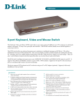
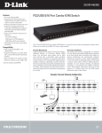
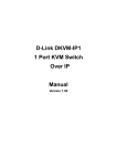
D-Link DKVM-16
16-Port Keyboard, Video,
and Mouse Switch
Manual
Version 1.2
Building Networks for People
08/26/03
Contents
Package Contents ................................................................................3
Introduction............................................................................................4
Features and Benefits ...........................................................................5
Hardware Installation .............................................................................6
Using the DKVM-16 ............................................................................12
Daisy-Chaining the DKVM-16 .............................................................16
Hot Plug ..............................................................................................17
Troubleshooting ...................................................................................21
Specifications .....................................................................................25
Warranty and Registration ...................................................................26
Contacting Technical Support ..............................................................29
2
Package Contents
Contents of Package:
! D-Link DKVM-16 16-Port Keyboard, Video, and Mouse
Switch
! 1 DC12V, 1A Power Adapter
! 3 sets of 3 in1 KVM Cable Kits
(1 set: 3 ft. 3-in-1 Cable Kit to daisy chain, 2 sets: 6 ft. 3 in 1
Cable to PC)
! 2 DB-9 to 6-pin Mini-DIN Mouse Converters
! 2 DIN 5-pin to 6-pin Mini-DIN Keyboard Converters
! Manual
! 2 Rack Mount Brackets
8 Screws
If any of the above items are missing, please contact your reseller.
System Requirements:
Computer
! One VGA, SVGA, or Multisync monitor
! One PS/2 mouse or serial (DB-9) mouse port
! One PS/2 keyboard or AT (5-pin DIN) keyboard port
Console
! One VGA, SVGA, or Multisync video card or port
! One PS/2 (6-pin mini-DIN)
! One PS/2 (6-pin mini-DIN)
3
Introduction
The D-Link DKVM-16 is a Keyboard, Video and Mouse KVM switch that
allows you to control up to 16 server computers using one keyboard, mouse,
and monitor. It is easy to use, powerful, and scalable. Each DKVM-16 port
has a dedicated microprocessor to intelligently manage port traffic and
allows simultaneous boot-ups for all attached PCs. The advanced
microprocessor technology also saves CAPSLOCK, NUMLOCK, and
SCROLL LOCK status for each PC. Two control buttons located on the front
panel give you one touch access to your attached PCs and the user-friendly
on-screen display menu allows you to configure your DKVM-16 switch’s
settings. The daisy chain port allows up to 8 DKVM-16 KVM switches to be
stacked together for controlling as many as 128 computers. Featuring hotplug, auto-scan, keyboard hot keys and audible feedback, the DKVM-16
makes it simple to manage all of your server computers.
The DKVM-16 supports VGA, SVGA, and MultiSync monitors at up to 1920 X
1440 resolution. Integrated mouse conversion technology allows older AT
type computers with serial mouse ports to be connected to the DKVM-16
using the included serial-to-PS/2 mouse converter. Both AT and PS/2 type
keyboards are also supported, as well as the most popular mice, including
Microsoft® IntelliMouse® and Microsoft® IntelliMouse Explorer®.
4
Features and Benefits
! Allows users to control sixteen computers from one keyboard, mouse,
and monitor
! No software is required; each channel has a dedicated microprocessor
to intelligently manage the boot-up process for all your attached PCs
! Daisy-chain ports allow control over as many as 128 computers through
8 banks of DKVM-16 units
! Hot Plug provides the ability to add PCs or remove connected PCs for
maintenance without powering down the KVM Switch or PCs
! Auto detection of daisy-chain bank eliminates the need for DIP-switches
! On-Screen Display menu gives the user a visual interface to name and
select computers
! Supports eight character password protection
! Convenient On-Screen Display, push button, and keyboard Hot Key
commands for switching between PCs
! AutoScan mode
! Audible feedback when switching
! Automatically recalls CAPS LOCK, NUM LOCK and SCROLL LOCK key
status for each computer
! Supports VGA, SVGA and MultiSync monitors
! Integrated mouse conversion technology allows connection of AT type
computers that have serial mouse ports
! Supports up to 1920 x 1440 resolution at 200MHz Bandwidth
! Keyboard and mouse emulation for error-free boot ups
** !
Microsoft® IntelliMouse®, Microsoft Intellimouse Explorer support and
emulation
! Supports both AT and PS/2 type keyboards (AT requires AT - PS/2
adapter included)
! Uses standard KVM cables
5
Hardware Installation
Front Panel Layout
Current Active Bank Display
Current Active Port Display
Bank Select
Port Select
Power Switch
Rear Panel Layout
PS/2 Keyboard
Input
VGA Monitor Connector
PS/2 Keyboard
Output
PS/2 Mouse
Output
Daisy-Chain In Port
Console Port
(Daisy-Chain Out)
6
VGA Signal
Input
PC Port Connectors
PS/2 Mouse
Input
Hardware Installation (Continued)
WARNING
Make sure that all of your computers are powered off before attempting to
connect the cabling to avoid damage to your DKVM-16
Step 1
Find a convenient place to place your DKVM-16. Its 19" rack mount form factor makes it mountable on a 19" rack. When mounting to a rack, attach the
included brackets to the side panels of the DKVM-16. Take note of the length
of your cables so that your computers, DKVM-16, keyboard, mouse, and monitor are distanced properly.
Step 2
Connect the monitor console to the DKVM-16. Connect the attached cable, or
the one included with your monitor, to the HD DB-15 female port, labeled with
the monitor symbol at the CONSOLE connector on the back of the DKVM-16.
7
Hardware Installation (Continued)
Step 3
Connect the keyboard console to the DKVM-16. If you have an AT type keyboard, you will need an AT to PS/2 adapter.
Step 4
Connect the mouse console to the DKVM-16. If you have an older mouse with
9 pins, you will need to use the 9 to 5 pin mouse converter that is included with
the DKVM-16.
8
Hardware Installation (Continued)
Step 5
Connect one end of the included VGA cable (15-pin HDDB Male / Male) to the
female connectors on the back of the PC. Connect the other end of the cable to
the rear panel of the DKVM-16. This step can be repeated for all PCs.
Back of PC
Step 6
Using the included 3-in-1 cable, locate the mouse connector (green) and connect one end to the PS/2 mouse port on the back panel of the computer, and
the other end to the PC1 PS/2 mouse port on the back panel of the DKVM-16.
If there are not enough PS/2 ports on the computer, you can choose a serial
port for the mouse connection. Be sure to add a serial to PS/2 converter included with the DKVM-16 before connecting the 3-in-1 cable to the computer.
Back of PC
9
Hardware Installation (Continued)
Step 7
Using the included 3-in-1 cable, locate the keyboard connector (purple) and
connect one end to the PS/2 keyboard port on the back panel of the computer,
and the other end to the PC1 PS/2 keyboard port on the back panel of the
DKVM-16. If your computer has an AT type keyboard port, you will need to use
the PS/2 to AT keyboard adapter included with the DKVM-16.
Back of PC
Step 8
Double-check all of your connections. Make sure that the keyboard and mouse
cables are connected to the correct ports.
Step 9
Repeat steps 5 through 8 for the remainder of the computers.
Step 10
Attach the power supply to the DKVM-16 unit and plug the other end into an
electrical receptacle. When you see the LED for Port 1 light up and hear a
beep, switch on your PCs and monitor.
Note: To maintain stable operation of the DKVM-16, please keep the unit powered
using the power adapter when in use, especially when the DKVM-16 is in a daisychain stack.
10
Hardware Installation (Continued)
Step 11
Now power up all computers simultaneously. The first computer will be shown
on the monitor. You may check to see if the mouse, keyboard, and monitor
work after the computer has booted up. If this is OK, use the “Select” button to
choose the next computer and verify the functionality in the same manner. If
you find errors, recheck all cables for proper connections before going to the
trouble-shooting section of this manual.
Note: Please do not switch the PC ports (i.e. do not press the “push” button of the
KVM switch or run Hot Key) while the computers are in the boot-up process. Normally, during the boot-up process, each PC will communicate with the keyboard
and mouse. If you switch PC ports on the KVM at this time, it will cause communication errors or initialization failures between the PC and keyboard or mouse.
11
Using the DKVM-16
The “Power On” State of the DKVM-16
When you power on the KVM switch, it will prompt you for the password; the
default value is eight zeros – “00000000”. Please enter eight zeros and enter
the same value in the retype field.
Note: If you are not familiar with the operation of the OSD manual, please do not
change the password (i.e. keep the default eight zero value). Otherwise, if you
forget your set password, you will need to contact the supplier (D-Link) to have the
unit reset.
The Push Buttons
Pressing the button allows you to cycle fowards and backwards through all
the ports.
1
2
3
..............
14
15
16
Bank
Port Status
PC
Port Status
The Display LEDs
When you select one of the sixteen PC ports and the PC is shut down or
disconnected, the selected port LED will flash. When you select one of the
sixteen PC ports and the PC is powered on, the selected port LED is lit.
12
Using the DKVM-16 (Continued)
The Reset Button
Pressing the select and bank button of the master switch simultaneously will
reset the KVM switch. This reset action returns the KVM switch back to the
initial state and will also recheck all of the slave banks which are connected
to the master DKVM-16.
If you add a new DKVM-16 as a slave bank, please use the reset button of
the master DKVM-16 to assign a new ID to it. The new slave bank will now
appear in the OSD menu. With the reset command, the PC ports of the
DKVM-16 will not be reset. The PC ports can only be reset by powering off
the DKVM-16.
The Keyboard Hot Keys
You can also manage and switch the DKVM-16 through simple hot key sequences. To send commands to the DKVM-16, the “SCROLL LOCK” key must
be pressed twice within 2 seconds. You will hear a beep confirming that the
keyboard is now in hot key mode. If you do not press any key in the hot key
mode within 2 seconds, the keyboard will revert back to Operation System control state.
Hot Key Commands
within 2 seconds
Scroll
Lock
+
Scroll
Lock
+
= Previous Port
Scroll
Lock
+
Scroll
Lock
+
= Next Port
Note: You can also press the “up arrow” key or “down arrow” key to select the
destination port.
13
Using the DKVM-16 (Continued)
Hot Key Commands (Continued)
Scroll
Lock
+
Scroll
Lock
+
Page
Up
= Previous Bank
Scroll
Lock
+
Scroll
Lock
+
Page
Down
= Next Bank
Note: Bank no. and port no. selection must be made using the numeric keys on the
keyboard. Numeric keys on the keypad are not available as a hot key command.
Scroll
Lock
+
Scroll
Lock
+
Bank No.
+
1~8
Port No.
1~16
= Select Bank
and PC port
Note: If you are trying to access a single digit port no. precede the port no. with a
zero (0). Example: To access bank 3 and port 5, press “SCROLL LOCK” twice
followed by the “305” value.
Ex.
Scroll
Lock
+
Scroll
Lock
+
Scroll
Lock
+
Scroll
Lock
+
Bank No.
+
3
B
Note: By default, the beeper function is ON.
14
0
= Beeper
+
Port No.
5
Using the DKVM-16 (Continued)
Hot Key Commands (Continued)
Scroll
Lock
+
Scroll
Lock
+
S
= Auto Scan
Note:
1. If you have already set up the scan mode command, DKVM-16 will issue
one beep to confirm each hop from one PC port to the next.
2. To exit Auto Scan Mode, press any key or the SPACE bar.
Scroll
Lock
+
Scroll
Lock
+
R
= OSD default
This screen will appear on your monitor
Note: The Rom reflash command will take approximately 1-2 minutes.
Scroll
Lock
+
Scroll
Lock
+
F
= Search PC name
This screen will appear on your monitor
Note: The Search PC name command starts with the 1st PC port.
Scroll
Lock
+
Scroll
Lock
+ Space Bar = On Screen Display Manual
15
Daisy-Chaining the DKVM-16
Please closely follow the steps below to daisy-chain your DKVM-16 units. You
can daisy chain up to 8 DKVM-16s.
Step 1
Connect your keyboard, mouse, and monitor to the console port (white color
block) of the master KVM bank (bank1).
Step 2
Use the 3-in-one Cable Kit to connect the daisy-chain port of bank 1 to the
console port (white color block) of the 2nd KVM switch.
Step 2
Please repeat step 2 to daisy-chain up to as many as 8 DKVM-16s.
Please use the attached 3 feet 3- in-one Cable Kit to daisy chain the
KVM Switches.
Bank 1
MASTER (Bank 1)
Bank 2
Slave (Bank 2)
Bank 3
Slave (Bank 3)
Bank 8
Slave (Bank 8)
16
Hot Plug
The DKVM-16 supports the “Hot Plug” function for easy addition or removal of
PCs. The user can arrange or maintain PCs as follows:
1.
A PC can be disconnected and reconnected to the same or different port
of the DKVM-16 without having to power it off as long as it is not the master
daisy-chain port.
2.
When the master port is active and selected, you must switch to a different
port before changing the configuration, and then you can switch back to
the master port.
3.
You may unplug the mouse or the keyboard from the console port and
plug it back in at any time.
Note: Some Operating Systems like SCO Unix are unable to support the Hot Plug
function. If you apply the Hot Plug function to this kind of Operating System, it will
cause unpredictable behaviors or shut down the PC. Before attempting to use the
Hot Plug function, please make sure it is supported by your Operating System and
software.
17
On Screen Display Operation
When you select the On Screen Display Operation manual window using the
“Hot Key” function, the following on screen display will appear on your monitor.
Bank number
BANK : 1
PC Name List. Factory default names are listed. You
can define your PC name up
to 8 characters
The sun symbol indicates
that the system is powered on
Change Password allows the
user to change the password
used to access all connected
systems
Specifies how long this onscreen display will remain on
your computer screen. Default time is 10 sec. You can
modify the value from 05-99
sec.
Scan Time sets the DKVM16 to switch automatically between PC ports in intervals.
Default scan time is 10 sec.
and maximum time is 99 sec.
You can use the up or down
arrow key to select the port
destination by PC name.
18
“CONSOLE ON/OFF” lets you
select the console access of the
KVM swith. “ON” allows any user
to use the console without password authentication. The factory
default is “OFF”.
On Screen Display Operation
(Continued)
CHANGE PASSWORD
The Change Password function allows the user to change the password used
to access all connected PC systems. The default password is 8 digits,
“00000000”.
The Enter Password window appears when you select this item and press
enter. The maximum password is eight digits. After you key in the password
and press the Enter key, another window appears to conform your typed password.
You must retype the new password to confirm the password change. The
following window appears to confirm the completion of your password change.
CONSOLE ON/OFF
The Console On/Off function lets you select the console access of the KVM
switch. If you select “CONSOLE ON”, any sure can use the console. If you
select “CONSOLE OFF” (factory default is OFF state), a password must be
entered to use the console. When you enter the password and pass the KVM
switch authentication, the console will be set to ON. After you finish using the
KVM switch, remember to set the CONSOLE On state to OFF to ensure password authentication.
Note: If you reset the KVM switch, or there is a power failure, the CONSOLE will be set to the OFF state.
19
On Screen Display Operation
(Continued)
ARROW KEYS (!
!/ " )
You can use the up arrow key “!” or the down arrow key “"” to select the port
destination by PC name. After you have selected the PC port, you can press
the “ENTER” Key to select the PC port you want immediately.
You can also use the “PgUp” key or the “PgDn” key for selecting the previous
or the next Bank no.
Pressing the “INS” key edits the PC name. When editing is finished, press the
“ENTER” key to save the information.
Use the “Tab” key to select items such as Bank, OSD, SCAN, CHANGE PASSWORD, CONSOLE ON/OFF, etc...
When you finish setting up the PC names and exit the OSD setting mode, you
will find the PC name displayed at the upper-left corner of your monitor. Now
you can use the “ESC” key to clear this screen.
102
If you want to revert the OSD back to factory default values, you can execute
“SCROLL LOCK”, “SCROLL LOCK”, and “R” keys in order. The Display LEDs
on the front panel will flash during the refresh process.
When the OSD values are back to the default setting, the Display LEDs on the
front panel will stop flashing.
20
Troubleshooting
General Problems
Q: The OSD menu does not display a “ “ on a channel where a computer is
connected and powered up.
A:
DKVM-16 updates “ “ every 2 seconds. Use the hot key to access
the OSD menu again and it should re-detect all the active channels.
Q: When cascading the MASTER unit does not see the slave unit(s).
A:
! Refer to the Installation section for information on how to
properly connect the daisy-chain cable.
! Make sure you are using the correct daisy-chain cable. Using
any other cable will not guarantee proper operation or video
quality.
! Reset all the slave units first and then reset master unit to
recover the lost slave unit.
! Although a power supply is not necessary to make the slave
unit work, try adding a power supply.
Monitor/VideoProblems
Q: I am getting ghost shadowing or fuzzy images on my monitor.
A:
! Check the cables and make sure that they are connected properly.
! Your resolution and/or refresh rate may be extremely high, or your
cable may be too long. Replace your VGA cables with coaxial,
double-shielded cables.
! Check to make sure that the power adapter is plugged in and is
working properly. Make sure the power switch is on.
! Lower your refresh rate and/or screen resolution settings.
21
Troubleshooting (Continued)
Keyboard Problems
Q: The keyboard is not detected or a keyboard error is reported during boot-up.
A:
! Check the cables and make sure that they are connected properly to the correct ports.
! Check to make sure that the power adapter is plugged in and is
working properly. Make sure the power switch is on.
! Do not press any keys on the keyboard while the selected computer is booting up. This applies to any PC, whether it is standalone or connected to a DKVM-16.
Q: The computer boots up correctly, but the keyboard does not work.
A:
! Check the cables and make sure that they are connected properly to the correct ports.
! Check to make sure that the the keyboard works when directly
plugged into the cmoputers.
! Try a different keyboard, but use only 101, 102, or 104-key keyboards.
! Make sure that the keyboard driver is for 101,102, or 104-key
keyboards, and not old XT keyboards.
! Check to make sure that the power adapter is plugged in and is
working properly. Make sure that the power switch is on.
PS/2 Mouse Problems
Q: The mouse is not detected during boot up.
A:
! Check the cables and make sure that they are connected properly to the correct ports.
! Check your computer/motherboard documentation to make sure
that the PS/2 mouse port (or IRQ) is enabled.
! Make sure that the mouse is directly plugged into the computer.
22
Rebooting is necessary when trying this. If the computer still does
not detect the mouse, then there is a problem with your
computer’s PS/2 mouse port.
Troubleshooting (Continued)
Q: The computer boots up correctly, but the mouse does not work.
A:
! Check the cables and make sure that they are connected properly to the correct ports.
! Make sure that the mouse works when plugged into the computer. Rebooting is necessary when trying this. If the mouse
pointer still does not move, then either your PS/2 mouse port or
the mouse itself has a problem.
! Try using a different mouse.
! Make sure that the mouse is a true PS/2 mouse. A combo mouse
will work just as long as it is set for the PS/2 mode with the correct adapter. A serial-only mouse with a combo mouse adapter
WILL NOT work.
! Check to make sure that the power adapter is plugged in and is
working properly. Make sure that the power switch is on.
Q: When I switch from one port to another, mouse movement is completely
erratic. What do I do?
A:
Switch the console port to the problem PC port and power on this PC
again to recover the mouse.
Problems with Computers Using Serial Mouse Output
Note: The DKVM-16 has integrated mouse conversion technology. This technology
converts the PS/2 mouse signals at the console to serial mouse signals.
Q: The comptuer boots up correctly, but the serial mouse port of the PC does not
work.
A:
! Check the adapter and make sure that it is connected properly to
the correct ports.
! Make sure that the adapter pin is correct.
23
Troubleshooting (Continued)
Q: The wheel on the mouse does not work on my computer.
A:
! Make sure that the mouse is a Microsoft® Intellimouse® or
Microsoft® Intellimouse® Explorer®.
! The DKVM-16 does not support special wheel functions of certain mice.
Problems with the Power Supply
Q: The power switch is off or the power adapter is unplugged, but the switch
still works.
A:
The DKVM-16 draws power from the power adapter and the PC’s PS/2
port. Some PC’s PS/2 port can support enough power for the switch,
but some PS/2 ports (such as those on laptops) are unable to supply
enough power for the switch. In order to make sure the system works
properly, please do not turn the power switch off or remove the power
adapter from the switch.
Although the PCs connected to the DKVM-16 are able to support enough
power to the switch, the DKVM-16 requires a power adapter to daisychain more banks.
24
Specifications
Computer Connections
Display LED Indication
Keyboard
Mouse
Monitor
Cascade
Cascade Port
On Screen Display
19” Rack Mount
Cascade (Level)
Max. Access Pcs
Manual Selection
Hot Key
Switching Configuration
Keyboard State
Keyboard
Mouse
Resolution
Bandwidth
Enclosure
Storage (Celsius)
Dimensions
Weight (lbs)
Power Supply
:
:
:
:
:
:
:
:
:
:
:
:
:
:
:
:
:
:
:
:
:
:
:
:
16
3
6-pin Mini-DIN Female
6-pin Mini-DIN Female
15-pin HD DB type Female
Two 6-pin Mini-DIN + One 15-pin HDDB
1
Yes
Yes
8
128
Push Button
Yes
Buzzer
Saved and Restored
PS/2
PS/2
1920 x 1440
200Mhz
Metal
-20~60 C
16 x 9 x 3.25 in
7.7 lbs
DC 12V, 1A (AC power)
25
Subject to the terms and conditions set forth herein, D-Link Systems, Inc. (“D-Link”) provides this Limited
warranty for its product only to the person or entity that originally purchased the product from:
•
•
D-Link or its authorized reseller or distributor and
Products purchased and delivered within the fifty states of the United States, the District of
Columbia, U.S. Possessions or Protectorates, U.S. Military Installations, addresses with an
APO or FPO.
Limited Warranty: D-Link warrants that the hardware portion of the D-Link products described
below will be free from material defects in workmanship and materials from the date of original retail
purchase of the product, for the period set forth below applicable to the product type (“Warranty
Period”), except as otherwise stated herein.
1-Year Limited Warranty for the Product(s) is defined as follows:
•
•
•
Hardware (excluding power supplies and fans) One (1) Year
Power Supplies and Fans One (1) Year
Spare parts and spare kits Ninety (90) days
D-Link’s sole obligation shall be to repair or replace the defective Hardware during the Warranty Period
at no charge to the original owner or to refund at D-Link’s sole discretion. Such repair or replacement
will be rendered by D-Link at an Authorized D-Link Service Office. The replacement Hardware need not
be new or have an identical make, model or part. D-Link may in its sole discretion replace the defective
Hardware (or any part thereof) with any reconditioned product that D-Link reasonably determines is
substantially equivalent (or superior) in all material respects to the defective Hardware. Repaired or
replacement Hardware will be warranted for the remainder of the original Warranty Period from the date
of original retail purchase. If a material defect is incapable of correction, or if D-Link determines in its
sole discretion that it is not practical to repair or replace the defective Hardware, the price paid by the
original purchaser for the defective Hardware will be refunded by D-Link upon return to D-Link of the
defective Hardware. All Hardware (or part thereof) that is replaced by D-Link, or for which the
purchase price is refunded, shall become the property of D-Link upon replacement or refund.
Limited Software Warranty: D-Link warrants that the software portion of the product (“Software”)
will substantially conform to D-Link’s then current functional specifications for the Software, as set
forth in the applicable documentation, from the date of original retail purchase of the Software for a
period of ninety (90) days (“Warranty Period”), provided that the Software is properly installed on
approved hardware and operated as contemplated in its documentation. D-Link further warrants that,
during the Warranty Period, the magnetic media on which D-Link delivers the Software will be free of
physical defects. D-Link’s sole obligation shall be to replace the non-conforming Software (or defective
media) with software that substantially conforms to D-Link’s functional specifications for the Software
or to refund at D-Link’s sole discretion. Except as otherwise agreed by D-Link in writing, the replacement
Software is provided only to the original licensee, and is subject to the terms and conditions of the
license granted by D-Link for the Software. Software will be warranted for the remainder of the original
Warranty Period from the date or original retail purchase. If a material non-conformance is incapable of
correction, or if D-Link determines in its sole discretion that it is not practical to replace the nonconforming Software, the price paid by the original licensee for the non-conforming Software will be
refunded by D-Link; provided that the non-conforming Software (and all copies thereof) is first returned
to D-Link. The license granted respecting any Software for which a refund is given automatically
terminates.
Non-Applicability of Warranty: The Limited Warranty provided hereunder for hardware and
software of D-Link’s products will not be applied to and does not cover any refurbished product and
any product purchased through the inventory clearance or liquidation sale or other sales in which DLink, the sellers, or the liquidators expressly disclaim their warranty obligation pertaining to the product
and in that case, the product is being sold “As-Is” without any warranty whatsoever including, without
limitation, the Limited Warranty as described herein, notwithstanding anything stated herein to the
contrary.
26
Submitting A Claim: The customer shall return the product to the original purchase point based on its
return policy. In case the return policy period has expired and the product is within warranty, the
customer shall submit a claim to D-Link as outlined below:
•
The customer must submit with the product as part of the claim a written description of the
Hardware defect or Software nonconformance in sufficient detail to allow D-Link to confirm
the same.
•
The original product owner must obtain a Return Material Authorization (“RMA”) number from
the Authorized D-Link Service Office and, if requested, provide written proof of purchase of
the product (such as a copy of the dated purchase invoice for the product) before the
warranty service is provided.
•
After an RMA number is issued, the defective product must be packaged securely in the
original or other suitable shipping package to ensure that it will not be damaged in transit, and
the RMA number must be prominently marked on the outside of the package. Do not include any
manuals or accessories in the shipping package. D-Link will only replace the defective portion
of the Product and will not ship back any accessories.
•
The customer is responsible for all in-bound shipping charges to D-Link. No Cash on Delivery
(“COD”) is allowed. Products sent COD will either be rejected by D-Link or become the
property of D-Link. Products shall be fully insured by the customer and shipped to D-Link
Systems, Inc., 53 Discovery Drive, Irvine, CA 92618. D-Link will not be held responsible
for any packages that are lost in transit to D-Link. The repaired or replaced packages will be
shipped to the customer via UPS Ground or any common carrier selected by D-Link, with
shipping charges prepaid. Expedited shipping is available if shipping charges are prepaid by
the customer and upon request.
D-Link may reject or return any product that is not packaged and shipped in strict compliance with the
foregoing requirements, or for which an RMA number is not visible from the outside of the package. The
product owner agrees to pay D-Link’s reasonable handling and return shipping charges for any product
that is not packaged and shipped in accordance with the foregoing requirements, or that is determined
by D-Link not to be defective or non-conforming.
What Is Not Covered: This limited warranty provided by D-Link does not cover: Products, if in D-Link’s
judgment, have been subjected to abuse, accident, alteration, modification, tampering, negligence, misuse,
faulty installation, lack of reasonable care, repair or service in any way that is not contemplated in the
documentation for the product, or if the model or serial number has been altered, tampered with, defaced
or removed; Initial installation, installation and removal of the product for repair, and shipping costs;
Operational adjustments covered in the operating manual for the product, and normal maintenance;
Damage that occurs in shipment, due to act of God, failures due to power surge, and cosmetic damage;
Any hardware, software, firmware or other products or services provided by anyone other than DLink; Products that have been purchased from inventory clearance or liquidation sales or other sales in
which D-Link, the sellers, or the liquidators expressly disclaim their warranty obligation pertaining to the
product. Repair by anyone other than D-Link or an Authorized D-Link Service Office will void this
Warranty.
Disclaimer of Other Warranties: EXCEPT FOR THE LIMITED WARRANTY SPECIFIED HEREIN, THE
PRODUCT IS PROVIDED “AS-IS” WITHOUT ANY WARRANTY OF ANY KIND WHATSOEVER INCLUDING,
WITHOUT LIMITATION, ANY WARRANTY OF MERCHANTABILITY, FITNESS FOR A PARTICULAR PURPOSE
AND NON-INFRINGEMENT. IF ANY IMPLIED WARRANTY CANNOT BE DISCLAIMED IN ANY TERRITORY
Limitation of Liability: TO THE MAXIMUM EXTENT PERMITTED BY LAW, D-LINK IS NOT LIABLE
UNDER ANY CONTRACT, NEGLIGENCE, STRICT LIABILITY OR OTHER LEGAL OR EQUITABLE THEORY
FOR ANY LOSS OF USE OF THE PRODUCT, INCONVENIENCE OR DAMAGES OF ANY CHARACTER,
WHETHER DIRECT, SPECIAL, INCIDENTAL OR CONSEQUENTIAL (INCLUDING, BUT NOT LIMITED TO,
DAMAGES FOR LOSS OF GOODWILL, LOSS OF REVENUE OR PROFIT, WORK STOPPAGE, COMPUTER
FAILURE OR MALFUNCTION, FAILURE OF OTHER EQUIPMENT OR COMPUTER PROGRAMS TO WHICH DLINK’S PRODUCT IS CONNECTED WITH, LOSS OF INFORMATION OR DATA CONTAINED IN, STORED ON,
OR INTEGRATED WITH ANY PRODUCT RETURNED TO D-LINK FOR WARRANTY SERVICE) RESULTING
FROM THE USE OF THE PRODUCT, RELATING TO WARRANTY SERVICE, OR ARISING OUT OF ANY
BREACH OF THIS LIMITED WARRANTY, EVEN IF D-LINK HAS BEEN ADVISED OF THE POSSIBILITY OF
SUCH DAMAGES. THE SOLE REMEDY FOR A BREACH OF THE FOREGOING LIMITED WARRANTY IS
REPAIR, REPLACEMENT OR REFUND OF THE DEFECTIVE OR NON-CONFORMING PRODUCT. THE MAXIMUM
LIABILITY OF D-LINK UNDER THIS WARRANTY IS LIMITED TO THE PURCHASE PRICE OF THE PRODUCT
COVERED BY THE WARRANTY. THE FOREGOING EXPRESS WRITTEN WARRANTIES AND REMEDIES
ARE EXCLUSIVE AND ARE IN LIEU OF ANY OTHER WARRANTIES OR REMEDIES, EXPRESS, IMPLIED OR
STATUTORY
27
Governing Law: This Limited Warranty shall be governed by the laws of the State of California. Some
states do not allow exclusion or limitation of incidental or consequential damages, or limitations on how
long an implied warranty lasts, so the foregoing limitations and exclusions may not apply. This limited
warranty provides specific legal rights and the product owner may also have other rights which vary
from state to state.
Trademarks: D-Link is a registered trademark of D-Link Systems, Inc. Other trademarks or registered
trademarks are the property of their respective manufacturers or owners.
Copyright Statement: No part of this publication or documentation accompanying
this Product may be reproduced in any form or by any means or used to make any
derivative such as translation, transformation, or adaptation without permission from
D-Link Corporation/D-Link Systems, Inc., as stipulated by the United States Copyright
Act of 1976. Contents are subject to change without prior notice. Copyright© 2002 by
D-Link Corporation/D-Link Systems, Inc. All rights reserved.
CE Mark Warning: This is a Class B product. In a domestic environment, this product may cause radio
interference, in which case the user may be required to take adequate measures.
FCC Statement: This equipment has been tested and found to comply with the limits for a Class B
digital device, pursuant to part 15 of the FCC Rules. These limits are designed to provide reasonable
protection against harmful interference in a residential installation. This equipment generates, uses, and
can radiate radio frequency energy and, if not installed and used in accordance with the instructions,
may cause harmful interference to radio communication. However, there is no guarantee that interference
will not occur in a particular installation. If this equipment does cause harmful interference to radio or
television reception, which can be determined by turning the equipment off and on, the user is encouraged
to try to correct the interference by one or more of the following measures:
•
•
•
•
Reorient or relocate the receiving antenna.
Increase the separation between the equipment and receiver.
Connect the equipment into an outlet on a circuit different from that to which the receiver is
connected.
Consult the dealer or an experienced radio/TV technician for help.
For detailed warranty outside the United States, please contact corresponding local
D-Link office.
Register online your D-Link product at http://support.dlink.com/register/
28
Technical Support
You can find software updates and user documentation on the D-Link website.
D-Link provides free technical support for customers within the United States and
within Canada for the duration of the warranty period on this product.
U.S. and Canadian customers can contact D-Link Technical Support through our
website, or by phone.
Tech Support for customers within the United States:
D-Link Technical Support over the Telephone:
(877) 453-5465
24 hours a day, seven days a week.
D-Link Technical Support over the Internet:
http://support.dlink.com
email:[email protected]
Tech Support for customers within Canada:
D-Link Technical Support over the Telephone:
(800) 361-5265
Monday to Friday 8:30am to 9:00pm EST
D-Link Technical Support over the Internet:
http://support.dlink.ca
email:[email protected]
29
30