1
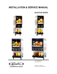
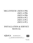
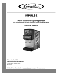
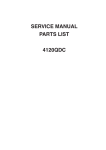
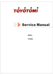
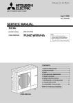
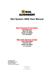
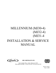
QUEST ELITE QLT 2000 Operator’s, Installation and Service Manual Release Date: December 10, 2013 Publication Number: 620058442 Revision Date: January 08, 2015 Revision: C Visit the Cornelius web site at www.cornelius.com for all your Literature needs. The products, technical information, and instructions contained in this manual are subject to change without notice. These instructions are not intended to cover all details or variations of the equipment, nor to provide for every possible contingency in the installation, operation or maintenance of this equipment. This manual assumes that the person(s) working on the equipment have been trained and are skilled in working with electrical, plumbing, pneumatic, and mechanical equipment. It is assumed that appropriate safety precautions are taken and that all local safety and construction requirements are being met, in addition to the information contained in this manual. This Product is warranted only as provided in Cornelius’ Commercial Warranty applicable to this Product and is subject to all of the restrictions and limitations contained in the Commercial Warranty. Cornelius will not be responsible for any repair, replacement or other service required by or loss or damage resulting from any of the following occurrences, including but not limited to, (1) other than normal and proper use and normal service conditions with respect to the Product, (2) improper voltage, (3) inadequate wiring, (4) abuse, (5) accident, (6) alteration, (7) misuse, (8) neglect, (9) unauthorized repair or the failure to utilize suitably qualified and trained persons to perform service and/or repair of the Product, (10) improper cleaning, (11) failure to follow installation, operating, cleaning or maintenance instructions, (12) use of “non-authorized” parts (i.e., parts that are not 100% compatible with the Product) which use voids the entire warranty, (13) Product parts in contact with water or the product dispensed which are adversely impacted by changes in liquid scale or chemical composition. Contact Information: To inquire about current revisions of this and other documentation or for assistance with any Cornelius product contact: www.cornelius.com 800-238-3600 Trademarks and Copyrights: This document contains proprietary information and it may not be reproduced in any way without permission from Cornelius. This document contains the original instructions for the unit described. CORNELIUS INC 101 Regency Drive Glendale Heights, IL Tel: + 1 800-238-3600 Printed in U.S.A. TABLE OF CONTENTS Safety Instructions . . . . . . . . . . . . . . . . . . . . . . . . . . . . . . . . . . . . . . . . . . . . . . . . . . . . . . . . . . . . . . . . 1 Read and Follow ALL Safety Instructions . . . . . . . . . . . . . . . . . . . . . . . . . . . . . . . . . . . . . . . . . . . . . 1 Safety Overview . . . . . . . . . . . . . . . . . . . . . . . . . . . . . . . . . . . . . . . . . . . . . . . . . . . . . . . . . . . . . 1 Recognition . . . . . . . . . . . . . . . . . . . . . . . . . . . . . . . . . . . . . . . . . . . . . . . . . . . . . . . . . . . . . . . . . 1 Different Types of Alerts . . . . . . . . . . . . . . . . . . . . . . . . . . . . . . . . . . . . . . . . . . . . . . . . . . . . . . . . . . 1 Safety Tips . . . . . . . . . . . . . . . . . . . . . . . . . . . . . . . . . . . . . . . . . . . . . . . . . . . . . . . . . . . . . . . . . . . . 1 Qualified Service Personnel . . . . . . . . . . . . . . . . . . . . . . . . . . . . . . . . . . . . . . . . . . . . . . . . . . . . . . . 1 Safety Precautions . . . . . . . . . . . . . . . . . . . . . . . . . . . . . . . . . . . . . . . . . . . . . . . . . . . . . . . . . . . . . . 2 Shipping And Storage . . . . . . . . . . . . . . . . . . . . . . . . . . . . . . . . . . . . . . . . . . . . . . . . . . . . . . . . . . . . 2 Unit Specifications . . . . . . . . . . . . . . . . . . . . . . . . . . . . . . . . . . . . . . . . . . . . . . . . . . . . . . . . . . . . . . . . 3 Installation instructions . . . . . . . . . . . . . . . . . . . . . . . . . . . . . . . . . . . . . . . . . . . . . . . . . . . . . . . . . . . . 4 Receiving . . . . . . . . . . . . . . . . . . . . . . . . . . . . . . . . . . . . . . . . . . . . . . . . . . . . . . . . . . . . . . . . . . . . . 4 Unpacking . . . . . . . . . . . . . . . . . . . . . . . . . . . . . . . . . . . . . . . . . . . . . . . . . . . . . . . . . . . . . . . . . . . . . 4 Counter Location . . . . . . . . . . . . . . . . . . . . . . . . . . . . . . . . . . . . . . . . . . . . . . . . . . . . . . . . . . . . . . . . 4 Recommended Clearance . . . . . . . . . . . . . . . . . . . . . . . . . . . . . . . . . . . . . . . . . . . . . . . . . . . . . 4 Installation . . . . . . . . . . . . . . . . . . . . . . . . . . . . . . . . . . . . . . . . . . . . . . . . . . . . . . . . . . . . . . . . . . . . 5 Electrical Connection . . . . . . . . . . . . . . . . . . . . . . . . . . . . . . . . . . . . . . . . . . . . . . . . . . . . . . . . . 5 Power Supply . . . . . . . . . . . . . . . . . . . . . . . . . . . . . . . . . . . . . . . . . . . . . . . . . . . . . . . . . . . . . . . 5 Water Booster System . . . . . . . . . . . . . . . . . . . . . . . . . . . . . . . . . . . . . . . . . . . . . . . . . . . . . . . . 5 Electric Booster Installation Details . . . . . . . . . . . . . . . . . . . . . . . . . . . . . . . . . . . . . . . . . . . . 5 Gas-operated Booster Installation Details . . . . . . . . . . . . . . . . . . . . . . . . . . . . . . . . . . . . . . . 5 Booster Installation Notes: . . . . . . . . . . . . . . . . . . . . . . . . . . . . . . . . . . . . . . . . . . . . . . . . . . . . . 6 Water Connection . . . . . . . . . . . . . . . . . . . . . . . . . . . . . . . . . . . . . . . . . . . . . . . . . . . . . . . . . . . . 6 Flushing System . . . . . . . . . . . . . . . . . . . . . . . . . . . . . . . . . . . . . . . . . . . . . . . . . . . . . . . . . . . . . 7 Filling the Water Bath . . . . . . . . . . . . . . . . . . . . . . . . . . . . . . . . . . . . . . . . . . . . . . . . . . . . . . . . . 7 Programming the Portion Control . . . . . . . . . . . . . . . . . . . . . . . . . . . . . . . . . . . . . . . . . . . . . . . . 8 Loading With Concentrate Pouches – 6.5 Liters . . . . . . . . . . . . . . . . . . . . . . . . . . . . . . . . . . . . . 9 Loading with Concentrate Pouches – 3.0 & 4.5 Liters . . . . . . . . . . . . . . . . . . . . . . . . . . . . . . . 10 Connecting the silicone tube onto the Mixing Chamber . . . . . . . . . . . . . . . . . . . . . . . . . . . . . . 11 Planned Maintenance . . . . . . . . . . . . . . . . . . . . . . . . . . . . . . . . . . . . . . . . . . . . . . . . . . . . . . . . . . . 13 Daily – Flushing the system . . . . . . . . . . . . . . . . . . . . . . . . . . . . . . . . . . . . . . . . . . . . . . . . . . . 13 Weekly – Sanitizing Dispense Parts . . . . . . . . . . . . . . . . . . . . . . . . . . . . . . . . . . . . . . . . . . . . . 14 Weekly – Check Ratio (Prodecure) . . . . . . . . . . . . . . . . . . . . . . . . . . . . . . . . . . . . . . . . . . . . . . 15 Monthly - Clean the Air Condenser Filter . . . . . . . . . . . . . . . . . . . . . . . . . . . . . . . . . . . . . . . . . 17 Semi-Annually - Clean the Water Inlet Strainer . . . . . . . . . . . . . . . . . . . . . . . . . . . . . . . . . . . . 18 Troubleshooting Guide . . . . . . . . . . . . . . . . . . . . . . . . . . . . . . . . . . . . . . . . . . . . . . . . . . . . . . . . . . . 19 Wiring Drawing for Quest Elite Qlt-2000 . . . . . . . . . . . . . . . . . . . . . . . . . . . . . . . . . . . . . . . . . . . . . 22 Qlt 2000 Final Assembly . . . . . . . . . . . . . . . . . . . . . . . . . . . . . . . . . . . . . . . . . . . . . . . . . . . . . . . . . 24 Qlt 2000 Door Assembly Reference (Pushbutton & Portion Control) . . . . . . . . . . . . . . . . . . . . . . . 25 Cabinet Assembly Reference . . . . . . . . . . . . . . . . . . . . . . . . . . . . . . . . . . . . . . . . . . . . . . . . . . . . . .26 Tank Cover Assembly . . . . . . . . . . . . . . . . . . . . . . . . . . . . . . . . . . . . . . . . . . . . . . . . . . . . . . . . . . .27 Refrigeration Frame Assembly Qlt 2000 . . . . . . . . . . . . . . . . . . . . . . . . . . . . . . . . . . . . . . . . . . . . .28 Platform Assembly QLT . . . . . . . . . . . . . . . . . . . . . . . . . . . . . . . . . . . . . . . . . . . . . . . . . . . . . . . . . .29 Valve Block Assembly . . . . . . . . . . . . . . . . . . . . . . . . . . . . . . . . . . . . . . . . . . . . . . . . . . . . . . . . . . .30 Electrical Box Assembly . . . . . . . . . . . . . . . . . . . . . . . . . . . . . . . . . . . . . . . . . . . . . . . . . . . . . . . . . .31 P/N 720521000 (For QLT Dispensers Only) . . . . . . . . . . . . . . . . . . . . . . . . . . . . . . . . . . . . . . . . . .31 Pouch Holder Assembly . . . . . . . . . . . . . . . . . . . . . . . . . . . . . . . . . . . . . . . . . . . . . . . . . . . . . . . . . .32 Recommended Spare Parts Based on 10 Units . . . . . . . . . . . . . . . . . . . . . . . . . . . . . . . . . . . . . . . .33 Quest Elite QLT 2000 SAFETY INSTRUCTIONS READ AND FOLLOW ALL SAFETY INSTRUCTIONS Safety Overview • Read and follow ALL SAFETY INSTRUCTIONS in this manual and any warning/caution labels on the unit (decals, labels or laminated cards). • Read and understand ALL applicable OSHA (Occupational Safety and Health Administration) safety regulations before operating this unit. Recognition Recognize Safety Alerts ! This is the safety alert symbol. When you see it in this manual or on the unit, be alert to the potential of personal injury or damage to the unit. DIFFERENT TYPES OF ALERTS ! DANGER: Indicates an immediate hazardous situation which if not avoided WILL result in serious injury, death or equipment damage. ! WARNING: Indicates a potentially hazardous situation which, if not avoided, COULD result in serious injury, death, or equipment damage. ! CAUTION: Indicates a potentially hazardous situation which, if not avoided, MAY result in minor or moderate injury or equipment damage. SAFETY TIPS • Carefully read and follow all safety messages in this manual and safety signs on the unit. • Keep safety signs in good condition and replace missing or damaged items. • Learn how to operate the unit and how to use the controls properly. • Do not let anyone operate the unit without proper training. This appliance is not intended for use by very young children or infirm persons without supervision. Young children should be supervised to ensure that they do not play with the appliance. • Keep your unit in proper working condition and do not allow unauthorized modifications to the unit. QUALIFIED SERVICE PERSONNEL ! WARNING: Only trained and certified electrical, plumbing and refrigeration technicians should service this unit. ALL WIRING AND PLUMBING MUST CONFORM TO NATIONAL AND LOCAL CODES. FAILURE TO COMPLY COULD RESULT IN SERIOUS INJURY, DEATH OR EQUIPMENT DAMAGE. Publication Number: 620058442 -1- © 2013-2015, Cornelius Inc Quest Elite QLT 2000 SAFETY PRECAUTIONS This unit has been specifically designed to provide protection against personal injury. To ensure continued protection observe the following: ! WARNING: Disconnect power to the unit before servicing following all lock out/tag out procedures established by the user. Verify all of the power is off to the unit before any work is performed. Failure to disconnect the power could result in serious injury, death or equipment damage. ! CAUTION: Always be sure to keep area around the unit clean and free of clutter. Failure to keep this area clean may result in injury or equipment damage. SHIPPING AND STORAGE ! CAUTION: Before shipping, storing, or relocating the unit, the unit must be sanitized and all sanitizing solution must be drained from the system. A freezing ambient environment will cause residual sanitizing solution or water remaining inside the unit to freeze resulting in damage to internal components. © 2013-2015, Cornelius Inc. -2- Publication Number: 620058442 Quest Elite QLT 2000 UNIT SPECIFICATIONS 15.15 24.85 19.30 29.30 30.7 30.04 8.65 2.10 Figure 1. Unit Dimension Model QUEST ELITE QLT - 2000, 115 VAC, 5 amps, 1 phase 60 hertz, 5.64 oz. (160 gms) R-134a refrigerant. Test press: High side 400 psi (2757.9 kilo pascals), (27.6 bar). Low side 88 psi (606.7 kilo pascals), (6.1 bar). Model QUEST ELITE QLT - 2000, 230 VAC, 2 amps, 1 phase 50 hertz, 5.64 oz. (160 gms) R-134a refrigerant. Test press: High side 400 psi (2757.9 kilo pascals), (27.6 bar). Low side 88 psi (606.7 kilo pascals), (6.1 bar). Model QUEST ELITE QLT - 2000, 220 VAC, 2 amps, 1 phase 60 hertz, 5.64 oz. (160 gms) R-134a refrigerant. Test press: High side 400 psi (2757.9 kilo pascals), (27.6 bar). Low side 88 psi (606.7 kilo pascals), (6.1 bar). Publication Number: 620058442 -3- © 2013-2015, Cornelius Inc Quest Elite QLT 2000 INSTALLATION INSTRUCTIONS RECEIVING Each unit is completely tested and inspected before shipment. At time of shipment, the carrier accepts the unit and any claim for damage must be made with the carrier. Upon receiving from the carrier, please, inspect the carton for visible damage. If damage exists, have the carrier make a note on the bill of lading and file a claim with the carrier. UNPACKING • Remove staples securing carton to pallet. • Lift carton up and off of unit. • Remove top insert and shipping bag. • Open upper cabinet door and remove installation kit. • Remove bolts securing unit to pallet. • Lift unit off of pallet. • Open the package, take the legs and secure them to the bottom of the unit. NOTE: Do not lay the unit on sides or on the back. This may cause vital oils to drain from the compressor resulting in damage during start-up and consequently voiding the warranty. Tilt the unit only when securing legs.If the unit is to be transported from the place where it was unpacked, do not remove the unit from the pallet. Transport it on the pallet to the installation site. COUNTER LOCATION Select a location in a well ventilated area, close to a grounded electrical outlet. If possible do not place the unit close to hot and/or steaming machines. The minimum Airflow clearance is: 4" (10.16 cm) in back and 12" (30.48 cm) on top, 4” (10.16cm) on sides and open to the front is required. The space between bottom of the unit and counter cannot be obstructed. IMPORTANT: Condenser air is drawn from the rear and discharged out the top. Failure to maintain clearance space will reduce capacity of the unit and cause premature compressor failure. Recommended Clearance 12” (30.48 cm) on top and 4” (10.16 cm) required in back for air circulation and 4”(10.16cm) at the sides of the unit. 4” 4” 4” 12” Figure 2. © 2013-2015, Cornelius Inc. -4- Publication Number: 620058442 Quest Elite QLT 2000 INSTALLATION Electrical Connection 6 ft. long (1.83 m) power cord with 3-prong plug attached to dispenser. Export models are shipped with a European plug. The plug is accessible after installation ! CAUTION: Only trained and certified electrical technicians should replace the power cord or the unit should be returned to an Authorized Service Center for power cord replacement.” The replacement cord must meet all requirements of the original equipment manufacturer. Failure to comply could result in serious injury, death or damage to the equipment. Power Supply 10 amps at 230 volts dedicated power supply. Water Booster System Install the Water Booster system on the dedicated Quest Elite Water supply line.Preferred location is in the Back Room Area and close to water- gas and/or electricity supply. Electric Booster Installation Details Figure 3. Gas-operated Booster Installation Details Figure 4. Publication Number: 620058442 -5- © 2013-2015, Cornelius Inc Quest Elite QLT 2000 Booster Installation Notes: Refer to the OEM manufacturers installation instructions Boosters and accumulator tanks should be fed with AMBIENT water only. To avoid condensation and premature equipment failure, do not install the water booster assembly in the refrigerated water supply circuit. To prevent pressure drops in the water supply line, use 3/8” / 9.5 mm ID supply lines only. Limit the amount of flow restrictions s.a. shut-off valves, manifolds and/or fitting. Water Connection 3/8 in. (0.95 cm) SAE male flare fitting on dispenser (see figure 5). Figure 5. The Quest Elite QLT 2000 series Juice Dispensing machine is designed to dispense juice at a high flow rate. It is very important that the incoming water line is dedicated for the unit, or at least does not have other machines connected which could cause a water surge, i.e., a dish washing or coffee machine. Notes: The unit should be fed by an insulated chilled water line from the soft drink beverage system. To achieve both optimal brix control and sanitation, assure that the incoming water pressure is at least 60 psi (4.2 bar) dynamic coming from the water booster system. IMPORTANT:The water supply should be consistent with proper water quality standards (neutral pH of 7.0 to 8.0), and should not be connected to a water softener. It is the installer’s responsibility to ensure that all water connections to the dispenser are sized, installed with adequate backflow protection and maintained to comply with Federal, State, and Local Laws. A. Secure the 3/8” (0.95 cm) swivel nut on the flexible supply tubing to the water inlet located at the rear of the dispenser. Make sure that the flared gasket is used (flared gasket P/N 311304000 is included with the installation kit). Figure 6. B. When securing flare nut, use backup wrench on male side of the inlet fitting (unit side) to prevent twisting of the copper tube inside the unit and/or possible damage to the water strainer/solenoid. © 2013-2015, Cornelius Inc. -6- Publication Number: 620058442 Quest Elite QLT 2000 Flushing System To properly prime the unit with water and remove air pockets in the system, open the cabinet door and make sure the protective dust cap is in place on top of the mixing chamber. Close the door and push the “STOP” Button for a few seconds. Repeat until a steady flow of water is observed. NOTE: Water splashing may occur during this purge cycle. Figure 7. Filling the Water Bath 1. Remove the Splash Panel (2 screws next to drip tray brackets) . 2. Release filling tube. 3. Remove the red cap. 4. Install the filling tube onto the RH dispense nozzle. 5. Assure that the RH mixing chamber is capped off to prevent the cabinet flooding with water. Figure 8. 6. Close the cabinet door, and push the dispenser button – dispense water only 7. Fill the water bath until water evacuates from the overflow 8. Evacuate approx. ½ liter of water. This Eliminates dripping from the overflow when building the ice bank 9. Install the red cap onto the filling tube, and replace into the bracket 10. Allow the cabinet to reach 4°C prior to load any concentrate into the cabinet. This takes approx. 1 hour Figure 9. Publication Number: 620058442 -7- © 2013-2015, Cornelius Inc Quest Elite QLT 2000 Programming the Portion Control 1. Simultaneously, press and hold “small” and “extra large” push button switches on the Portion Control Module until the “REFILL” light in the corner of the module starts blinking. Release the switches. The blinking light indicates the programming mode is active. 2. Place the cup under the white mixing valve nozzle and push the selected size button (small, medium, large, or extra large). Hold the button in until the cup fills to the desired portion, then release the button. Repeat the above procedure for the remaining sizes. 3. After programming all the drink sizes, press and release the “STOP BUTTON” to return the Portion Control to the operational mode. The blinking REFILL light will go out. REFILL Figure 10. If in future it is decided to change the portion size of the drinks, the individual sizes can be adjusted by the above procedure. It is not necessary to re-program every size. Additionally the portion control has a full memory retention in case of a power failure. To pour a drink without using a pre-programmed portion control size, simply push and hold the STOP BUTTON. Release when the glass is full. © 2013-2015, Cornelius Inc. -8- Publication Number: 620058442 Quest Elite QLT 2000 Loading With Concentrate Pouches – 6.5 Liters 1. Place the empty pouch holder on its back onto the counter. 2. Grab the pouch by the tube connector and place it vertically on the counter next to the pouch holder. Figure 11. 3. Locate the silicon tube through the slot, and slide the top of the pouch inwards. 4. Do not pull the silicone tube to guide the pouch into the pouch holder. Figure 12. 5. Tilt the pouch holder forward whilst pushing the connector and tube into the proper slot position. Figure 13. 6. Slide the pouch connector upwards / towards the front of the pouch holder Figure 14. 7. Massage the pouch to fill the pouch holder NOTE: Improper loading of the pouch into the pouch holder can cause: • Unable to load the pouch holder into the cabinet. • Excess remnant. • Ratio/Brix variations above standards. Figure 15. 8. Open the Quest Elite Cabinet Door and slide the pouch holder onto the shelf. Figure 16. Publication Number: 620058442 -9- © 2013-2015, Cornelius Inc Quest Elite QLT 2000 Loading with Concentrate Pouches – 3.0 & 4.5 Liters 1. Place the pouch holder on its side onto the counter.If applicable, first remove the empty pouch and discard. 2. To open, push the sides of container slightly inwards on both sides (see arrows) and simultaneously turn open the lid. Figure 17. 3. Turn the lid to face upwards or all the way down to the counter. Figure 18. 4. Locate the silicon tube through the slot, and place the pouch into the pouch holder. NOTE: • Do not pull the silicone tube • Load the concentrate pouch properly into the pouch holder • Avoid concentrate being trapped in the corners Figure 19. 5. Close the pouch holder lid. Figure 20. © 2013-2015, Cornelius Inc. - 10 - Publication Number: 620058442 Quest Elite QLT 2000 6. Open the cabinet door, open the QLT pump and slide the pouch holder onto the pouch holder shelf. 7. Locate the silicone tube into the pump and close the pump slide. Figure 21. Connecting the silicone tube onto the Mixing Chamber 1. Remove the Nozzle with the Static Mixer, remove the Mixing Chamber and place onto the drip tray 2. Position the silicone tube into the QLT pump Figure 22. 3. Close the pump and remove the red stopper from the silicone tube NOTE: • Verify that the tube is properly loaded, not jammed between the pump slides • With single 6.5 liter pouch operation, the left hand valve might be either disabled or used for dispensing still / chilled water Figure 23. Publication Number: 620058442 - 11 - © 2013-2015, Cornelius Inc Quest Elite QLT 2000 4. Connect the nipple of the mixing chamber onto the silicone tube 5. Hold the mixing chamber sideways when sliding the nipple onto the silicone tube Figure 24. 6. Slide the Mixing chamber in position and push firmly into the pump deck. ! CAUTION: Make sure that the lid of the mixing chamber is properly installed and screwed on tight. Failure doing so will cause the entire chamber to flood with drinks and eliminating the anti-splattering effect. Figure 25. 7. Replace the Nozzle and Static Mixer, and close the cabinet door Priming: Place a small cup onto the drip tray and press the cancel/Pour button for 2 seconds to prime the mixing system If only water leaves the nozzle, check if the RUN/FLUSH switch onto the pump platform is placed in the RUN position Figure 26. © 2013-2015, Cornelius Inc. - 12 - Publication Number: 620058442 Quest Elite QLT 2000 PLANNED MAINTENANCE Daily – Flushing the system 1. Set both flush switches to “Flush” position. 2. Open the cabinet door. Move both LH and RH flush switches from the “Run” position to the “Flush” position. Close the cabinet door. Figure 27. 3. Place small cold-drink cup under each dispensing nozzle. 4. Place a small, empty, cold-drink cup on the drip tray under the nozzles. Figure 28. 5. Flush nozzles. 6. Push the Cancel/Pour dispenser switches and hold down for 2 or 3 seconds, until clear water is dispensed from both nozzles Figure 29. 7. Reset the flush switches to “Run” position. 8. Open the cabinet door. Move the flush switches from the “Flush” position to the “Run” position. Close the cabinet door. Figure 30. 9. Clean nozzles and mixers. 10. Turn the nozzle to the left or right ¼ turn and pull down to remove the nozzle and static mixer. Take the nozzles and static mixers to the three-compartment-sink. Rinse both with hot tap water to remove any pulp. Figure 31. 11. Replace nozzles and mixers. 12. Reinstall the nozzles and static mixers on the dispenser. Figure 32. Publication Number: 620058442 - 13 - © 2013-2015, Cornelius Inc Quest Elite QLT 2000 13. Clean outside of cabinet. 14. Wipe down the outside of the cabinet and the splash panel with a cleaned towel. Place the towel in the soiled towel bucket. Figure 33. Weekly – Sanitizing Dispense Parts 1. Perform the DAILY Cleaning Procedures 2. Disconnect mixing chambers from concentrate pouch tubes and remove mixing chambers. 3. Remove the chambers by pulling it firmly toward you. NOTE:Do not open the pump while the concentrate tube is disconnected from the mixing chamber. Figure 34. 4. Disassemble the mixing chambers 5. Screw off the lids counter-clock-wise from the mixing chambers bodies prior to sanitizing. Figure 35. 6. Wash, rinse, and sanitize mixing chamber, nozzle, and static mixer. 7. Wash the mixing chamber, nozzle, and static mix at the three-compartment-sink. Be sure all pulp is removed. Rinse with hot tap water and sanitize the parts. Figure 36. 8. Reassemble the mixing chambers and reconnect to concentrate pouch tubes. 9. Reinstall the parts in the juice dispenser. Figure 37. 10. Reinstall nozzles and static mixers. 11. Reinstall the parts in the juice dispenser. 12. Clean outside of cabinet. 13. Wipe down the outside of the cabinet and the splash panel with a cleaned towel. Figure 38. © 2013-2015, Cornelius Inc. - 14 - Publication Number: 620058442 Quest Elite QLT 2000 14. Dispense a small portion juice to prime the mixing chambers. 15. Press the dispense button to fill a small cold-drink cup with juice. Discard the juice. Figure 39. Weekly – Check Ratio (Prodecure) 1. Turn the nozzles to the left or right ¼ turn and pull down to remove the nozzles and static mixers. Figure 40. 2. Disconnect mixing chambers from concentrate pouch tubes and remove mixing chambers. 3. Remove the mixing chambers by pulling firmly toward you. Figure 41. 4. Check the concentrate supply NOTE:Assure that the concentrate pouch is not near empty, properly loaded into the pouch holder and that the silicone tubes are properly installed into the pumps Figure 42. 5. Install the QLT syrup splitter assembly and connect the silicone tube onto the syrup tube. 6. To prevent incorrect ratio readings, do not pull or stretch the silicone tube while connecting to the splitter tube. Figure 43. 7. Close the cabinet door, place a medium cup onto the drip tray and under the splitter tubes and push the Cancel/Pour button for 1 second to prime the splitter tube and fill with concentrate Figure 44. Publication Number: 620058442 - 15 - © 2013-2015, Cornelius Inc Quest Elite QLT 2000 8. Place the RVC onto the drip tray and the water and concentrate chambers locating under the splitter tubes Figure 45. 9. Dispense Water and Concentrate into the RVC 10. Push the Cancel/Pour button until approx. 300 ~ 350 ml of water has dispensed into the RVC water chamber. Figure 46. 11. Read the RATIO from the RVC 12. Place the RVC onto a flat surface and read both water and syrup volumes. Figure 47. 13. Calculate the Water to Concentrate Ratio. 14. With standard Orange Juice, the Ratio 5 to 1 with a maximum of 5.2 and a minimum of 4.8. Ratio = Water ml/ Concentrate ml 15. Ratio too low: Increase water flow. 16. To correct too low ratio, increase the water flow. 17. Turn the water flow control screw to the right (clockwise) ¼ turn. Check the Ratio again by repeating above steps with a new sample in the RVC. Figure 48. 18. Ratio too high: Reduce water flow. 19. Turn the water flow control screw to the left (counterclockwise) ¼ turn. Check the Ratio again by repeating above steps with a new sample in the RVC. Figure 49. © 2013-2015, Cornelius Inc. - 16 - Publication Number: 620058442 Quest Elite QLT 2000 20. Replace the mixing chambers and reconnect to concentrate pouch tubes. 21. Reinstall the parts in the juice dispenser. 22. Sanitize the syrup splitter and put aside in a safe and clean location Figure 50. Monthly - Clean the Air Condenser Filter 1. Pull the magnetic filter off the rear panel of the juice dispenser. Figure 51. 2. Clean the filter in a bucket of warm soapy water. Figure 52. 3. Place the filter on a clean, sanitized towel to allow it to air dry. Figure 53. 4. Place the filter on the rear panel of the juice dispenser. Figure 54. Publication Number: 620058442 - 17 - © 2013-2015, Cornelius Inc Quest Elite QLT 2000 Semi-Annually - Clean the Water Inlet Strainer 1. Pull the AC plug from the wall outlet Figure 55. 2. Remove the right side panel from the dispenser. 3. Turn off the water supply to the dispenser. 4. Remove the access port from the “Y” shaped water inlet solenoid located on the right side of the dispenser. 5. Clean and reinstall the stainless steel water strainer. Figure 56. Annually - Cleaning the cabinet The cabinet bottom surface and walls should be inspected and cleaned annually following the instructions below. 1. Remove natural rubber nozzle bushing gasket and inspect it and Silicone RTV.If cracked, cleam off RTV and re-apply using kit P/N 729011013 per instructions provided with the Kit. 2. Re-apply nozzle bushing gaskets so that the edges lie flat ont the floor of the cabinet. 3. Clean the cabinet floor and walls of any spilled juice and let dry. Use a mild soap/detergent and plain water. 4. Re-install the pump platform in the reverse order given above. For more information, refer to the Planned Maintenance Cards found in the Appendix of this Manual. Daily maintenance tasks BE 20 D1Flush orange juice system. Weekly maintenance tasks BE 20 W1Sanitize orange juice system. BE 20 W2Check orange juice Ratio. Monthly maintenance tasks BE 20 M1Clean condenser filter. © 2013-2015, Cornelius Inc. - 18 - Publication Number: 620058442 Quest Elite QLT 2000 TROUBLESHOOTING GUIDE The following tables contain trouble-shooting information intended to aid an experienced service person in diagnosing operational problems that may occur. For further assistance, contact the Cornelius Customer Services department at 800-238-3600 between the hours of 7:30A.M. and 5:00P.M. Central Standard Time. You must have the model and serial number (Located on the right side of the dispenser) when calling. Symptom Probable Cause A. No power to dispenser due to tripped circuit breaker. Unit totally inoperative B. Loose or broken power supply connection inside dispenser. Remedy A. Reset circuit breaker. Confirm that breaker is correct size & no other equipment is operating on the same circuit. Also confirm that supply voltage is +/-10% of nameplate specification. B. Repair connection. A. Line voltage not within nameplate specifi- A. Contact an electrician. cation causing compressor overload to trip. B. No water in water ice bath or water level extremely low, exposing ice bank sensing probe. C. Defective Ice Bank Control or sensing probe. D. Cabinet fan inoperative resulting in warm concentrate (water continues to cool). No Cooling E. Compressor short cycles on overload. F. Compressor starts but hums & trips overload. G. Defective compressor overload or start capacitor. H. Compressor starts but does not switch off of start winding. D. Replace. E. Excessively high discharge pressure due to restricted condenser or inoperative condenser fan motor. F. Seized or shorted compressor, replace. G. Test & replace. H. Relay or compressor is defective. Test & replace faulty item. A. No water in dispenser. A. Restore water. B. Water supply line inside refrigerated cabinet disconnected from pump platform. B. Reconnect C. Water solenoid located on pump platform clogged or defective. C. Disassemble & clean solenoid. Replace if necessary. D. Main water solenoid/strainer located at the D. Remove & clean strainer. Confirm 24VDC rear of dispenser is clogged, binding or is present at solenoid during dispense. defective. Confirm solenoid coil is not open. Disassemble & clean solenoid. E. Water supply pressure is greater than 80 psi (5.5 bar) forcing BRIX flow control closed. F. Freeze-up of water coil in ice bath. Publication Number: 620058442 C. Replace. I. Repair leak, evacuate & recharge system. I. Refrigerant leak. No water dispensed, concentrate only B. Fill ice bath to proper water level. - 19 - E. Add external regulator & lower pressure to 50 psi (3.5 bar). F. Unplug dispenser & allow 2-4 hrs. to thaw. Check operation of agitator motor & ice bank control. Refrigeration system may be low on charge resulting in a deformed ice bank & freeze-up of water coil in ice bath. © 2013-2015, Cornelius Inc Quest Elite QLT 2000 Symptom Probable Cause Remedy A. Black service switch located on the rear of A. Turn on switch. the cabinet door in OFF position. No water & no concentrate, refrigeration is working. No concentrate dispensed, water only. B. White door switch open B. Door switch must be closed in order to dispense. Check switch operation & replace if necessary. C. 6.25 amp fuse inside front electrical box blown. C. Replace with 6.25, 250VAC slow blow fuse & test. D. No output from transformer. D. Confirm transformer output of 24VAC +/-2. Replace transformer if necessary. E. Defective voltage regulator board (VRB) located inside front electrical box. E. Measure across the VDC output of the board. There should be 28VDC present when the dispense button is pressed. Replace VRB if necessary. F. Defective dispense push button or portion control board. F. Test & replace if necessary. A. Concentrate container not fully engaged into receptacle on pump platform. A. Refer to Concentrate Loading section of this manual. B. Dispense/Flush lever in FLUSH position B. Move lever to DISPENSE position C. Concentrate too cold, not properly thawed. C. Concentrate should be 35 to 40°F (1.7 to 4.5°C) prior to loading. D. Defective pump motor. D. Replace pump motor. A. Ambient air around dispenser is too warm. A. Relocate dispenser. Warm drinks Water continuously drips from nozzle in OFF mode. Concentrate warm, water cold. BRIX problem B. Excessive demand on dispenser. B. Add water pre-cooler or second dispenser C. Dirty condenser coil. C. Clean condenser coil. D. Inoperative condenser fan. D. Replace condenser fan motor. E. Defective Ice Bank Control. E. Test & replace if necessary. F. Loss of refrigerant charge due to leak in system. F. Repair leak and recharge system. A. Main water solenoid at base of unit or water solenoid on pump platform not shutting off completely. A. Clean solenoid(s), replace parts as necessary (refer to Planned Maintenance section). A. Cabinet fan inoperable. A. Check/replace fan. B. Agitator motor/pump inoperable or restricted. B. Check/replace agitator motor. C. Loss of refrigerant charge due to leak in system. C. Repair leak & recharge system. A. Water supply pressure too low, less than 20 psi (1.4 bar) flowing water pressure. A. Correct water supply problem to ensure a constant 50 psi (3.5 bar) flowing to dispenser. B. Water flow control binding or spring is defective. C. Improperly thawed concentrate. BRIX changes as concentrate temperature changes (concentrate becomes thinner as temperature rises) © 2013-2015, Cornelius Inc. - 20 - B. Clean and/or replace parts as necessary. C. Concentrate should be 35 to 40°F (1.7 to 4.5°C) prior to loading. Publication Number: 620058442 Quest Elite QLT 2000 Symptom Probable Cause A. Pump motor defective. Pump inoperative Remedy A. 28VDC should be present at pump motor during dispense. If voltage is present & motor does not start, replace motor. B. No power to transformer or no 24VAC out- B. Confirm transformer has line voltage presput from transformer. ent on primary side. If no 24VAC output from secondary, replace transformer. C. Defective voltage regulator board (VRB) located inside front electrical box. C. Confirm board produces 28VDC present when dispense button is pressed (refer to Electrical Box Wiring Diagram for VDC output location). Replace VRB if necessary. D. Defective dispense control board (Push button or portion control). D. Test & replace if necessary. A. Push button or portion control pad stuck in A. Disconnect wire harness from rear of porON position. tion control and close the door. If unit does not dispense on its own, dispense control Machine continues to disboard is bad (stuck on). pense after dispense button is released or dispenses B. Relay on voltage regulator board (VRB) B. Disconnect 4-wire harness from lower right without operator input. stuck on. comer of VRB. If unit continues to dispense on its own VRB is defective (relay stuck on). Water leaking from the cabi- A. The O-ring from the cabinet quick connec- A. Replace the O-ring net through the cabinet tor might be damaged or missing. drain into the drip tray. Publication Number: 620058442 - 21 - © 2013-2015, Cornelius Inc Quest Elite QLT 2000 WIRING DRAWING FOR QUEST ELITE QLT-2000 Figure 57. © 2013-2015, Cornelius Inc. - 22 - Publication Number: 620058442 Quest Elite QLT 2000 Figure 58. Figure 59. Publication Number: 620058442 - 23 - © 2013-2015, Cornelius Inc Quest Elite QLT 2000 Illustrated Parts List QLT 2000 FINAL ASSEMBLY Figure 1. Item Item Part No. Description 1 620047969 Hinge Top Cover, Quest Elite 2/4 FL 2 620047744 Merchndsr Assy Qst2 2FL 3 620054876 Side Panel LH. Quest Elite 2/4 FL 4 Tray, Black W/Texture, Quest Elite 2 620049855 Drip FL 5 620708562 Cup Rest W/LOC Quest 2 STND 8.1 X 6 620048648 Splash Panel Guard, Quest Elite 2 FL 7 620715835 Nozzle Static Mixer ASMB 8 620049092 Tank Foamed Qste Finish 2FL 9 620054875 Side Panel RH. Quest Elite 2/4 FL Description Screw MA #8-32 TRPH 16 SS 19 70178 Screw MA #8-32 TRPH 16 SS 20 620047429 Brkt, Drip Tray, Right, QST 2/4 FL 620047428 Brkt, Drip Tray, Left, QST 2/4 FL 21 37958 Leg Level 4” 22 720201440 Brkt, Catch Strike Plate QST-NT 23 720701405 Screw TB D6-18 PAPH 12 SS 24 620048922 Kit Literature Pkg QST 2FL (not shown) 25 620048649 Label System Wiring Diagram QS 26 620047943 Harness Door, QST2, 2FL (not shown) to Power Cord QST2, 2/4FL 27 620048959 Harness (Not Shown) 10 620050923 Rear Panel, Quest 2 FL 13 620048898 Top Panel W/Cut, QST Elite 2 FL 28 11732 14 720704004 Door Catch, Female 2FL / 4FL Harness Assembly Platform SLJ 1000 (Not shown) Combined Compressor Condenser 29 620049320 Harn QST Elite 2/4FL (Not Shown) 16 620049566 Washer- Hinge Bottom QST Elite 2/4FL 17 620047782 Pin Latch Cabinet Qst2 2FL/4FL © 2013-2015, Cornelius Inc Part No. 18 0704105 - 24 - Publication Number: 620058442 Quest Elite QLT 2000 Illustrated Parts List QLT 2000 DOOR ASSEMBLY REFERENCE (PUSHBUTTON & PORTION CONTROL) 10 6 16 14 8 17 7 9 5 15 4 1 13 2 3 12 Figure 2. Item Part No. Description Item Part No. 12 620047753 Overlay Assembly, Pushbutton Control, Quest 1 2 3 4 5 620047750 Overlay Assembly, Portion Control, Quest Elite, 2/4 620047751 Bezel, Push button, Silver, Quest Elite, 2FL / 4FL 620047748 Latch Mounting Lock 14 620047761Graphics Merchndsr MM Europe Qste 2FL 26 15 620047760 Lens, Quest Elite, 2FL 16 620047745 Merchandiser, Quest Elite, 2FL Board Push button SLJ 49280001 Board Portion Control SLJ 620047754 Assembly, Door Foamed, Quest Elite, 2FL 7 620051427 Switch Rocker Unmarked Qste 2FL/4FL 8 720704005 Latch Door Male 9 620047759 Seal, Door, Quest Elite, 2FL 10 720500713 Switch Cut off 10 A MOM E6900A 11 Label Triangle Nozzle Indicator Mirror Finish 620049097 QST2 2FL/4FL Publication Number: 620058442 0704101 Screw MA 8-32 TRPH 12 SS 620052150 Label Daily Flush & Cleaning Quest Elite Qlt 17 620052151 Label Daily Flush & Cleaning SLJ Flush 620052153 Label Daily Cleaning QSTE Non Flush 620047679- LED Quest PCBA Backlight Family 100 6 729011214 Kit, Lock & Key Door Quest Elite 2FL/4FL 13 620047761 Graphic- Merch Generic QST2 2FL Bezel, Portion Control, Silver, Quest Elite, 2FL / 620047968 4 L 45018001 Description 629097007 18 19 NS - 25 - Kit 1, Flavor Strip Quest Elite, 2/4FL (Not shown) Kit 2, Flavor Strip Quest Elite, 2/4FL (Not 629097008 shown) Kit, Conversion PB to PC, QSTE 2FL (Not 729011218 Shown) 729011219 Kit, Conversion PC to PB, QSTE 2FL (Not Shown) 620050925 Label Rocker Switch Details, Qste,230v, 2/4FL © 2013-2015, Cornelius Inc. Quest Elite QLT 2000 Illustrated Parts List CABINET ASSEMBLY REFERENCE 15 14 Figure 3. Item 1 2 Part No. 620049842 Item Description Cabinet Assy QST Elite 2FL Modified Drain Part No. 6 620047970 Trim Bottom W/Insert, Quest Elite, 2FL 7 720201479 Bracket Dual Nozzle Block Quest 8 07040007 Screw Machine, #8-32 PAPH 28SS 720522100X Platform Asy Qlt Qst 2000 720506104 Fan Assembly 115/60/50 4.7 X 4.7X1.0 720506105 Fan Assembly 230/50/60 4.7 X 4.7 X1.0 9 Gasket Sealing Bowl Spout Fitg Insrt 3/8"NPT PP Brkt Hinge QST2 2FL/4FL 3 620047512 Guard, Fan EBM 9000 & 4000 11 S3354 4 620049556 Cabinet Heat Exchanger, Quest Elite, 2FL Fitting Push, Union Elbow, 3/8”X 1/2” LG 14 720200206 5 Description 720509206 © 2013-2015, Cornelius Inc 15 620047775 - 26 - Publication Number: 620058442 Quest Elite QLT 2000 Illustrated Parts List TANK COVER ASSEMBLY P/N 620047892 3 2 4 5 Figure 4. Item Publication Number: 620058442 Part No. Description 2 729011222 Kit Service Ice Probe Assy QSTE 2FL 3 720521000 Box Elec Asy Dc QST2 QLT 4 720501502 Coil, Water, QUEST 2, 2FL 5 620049563 Coil, Refrigeration QUEST Elite 2FL - 27 - © 2013-2015, Cornelius Inc. Quest Elite QLT 2000 Illustrated Parts List REFRIGERATION FRAME ASSEMBLY QLT 2000 Figure 5. Item Item 1 3 Part No. Description 629097391 Kit Comp 115V/60HZ QST 2 FL 629097392 Kit Comp 230V/50HZ QST 2 FL 629097393 Kit Comp 220V/60HZ QST 2 FL 620048659 Adapter, 1/4”FPT x 3/8”MF 620049959- 001 11 Cord Power Straight IEC60320-C13 Family 12 620049959- 003 Cord, Service 230V 4 5 6 13 620049959- 007 Cord Serv 200V 60 HZ IEC 60906-1 Part No. Description 560004366 Fan Axial Small 560003706 Fan, Condenser Assembly, 230V, Quest Elite 2FL 560004360 Motor- Fan 08W 120/60 Service 560004368 Grille Cond Fan Small 560004364 Shroud Cond Olympus Small 6775 Clip Tin CB14-832-4 620047655 Transformer, 115V, Quest Elite 2/4FL 620047654 Transformer, 230V, Quest Elite 2/4FL 620049959- 008 Cord Pwr ME Version QSTE 2/4FL 14 9649 Washer Comp Mount 620049959- 009 Cord PWR QSTE 2/4FL Cei-16/Vii Italian Plug 15 317781000 Bushing, Split 17 08474 Clip Spring 18 620058691 Suction HX Assembly, Quest Elite 2FL 620042742 Agitator Motor Assembly 115V 620042741 Agitator Motor Assembly 230V 620047892 Tank Cover Assembly, Quest Elit, 2FL 19 620049560 Grommet Ae Comp QST2 20 620058692 Line Discharge Quest 2Fl 729011138 Kit GIBC Field Quest (Not Shown) 440000901 Control Ice Bank 230V Global 21 49034 Tube Tygon 3/8ID X 5/8 440000902 Control Ice Bank 120/60 QST 22 620054202 Brkt Solenoid Quest Elite 2/4FL 8 620047891 Valve Water W/Solenoid, Quest Elite, 2/ 4FL 23 620049859 Tube Asy Water Inlet To HX QST2FL 9 620049857 Reducer, Elbow, 1/4” FPT x 3/8” Barb 10 620047114 2 Cubic Inches, Filter Dryer 7 © 2013-2015, Cornelius Inc - 28 - Publication Number: 620058442 Quest Elite QLT 2000 Illustrated Parts List PLATFORM ASSEMBLY QLT P/N 720522100X Figure 6. Item Part No. 1 2 3 07032001 0704105 720701001 4 11877 5 11887 6 11888 7 8 9 45046 45047 45048 10 45364001X Description Item Screw #8-18X 7/16 Type 25 HHW Screw MA #8-32 TRPH 16SS Rivet Platform Base Quest Jumper Assembly Read Flush QLT 180(Not Shown) Jumper Assembly Red Flush Switch AL (Not Shown) Harness Assembly Platform SLJT1000-2(Not Shown) Latch #2 Medium SS Guide Latch #2 MED Washer Latch #2 MED Chamber Mixing Assembly QLT 180 Day Publication Number: 620058442 - 29 - Part No. 11 12 13 14 45432 45508200X 45514100X 45542 15 55145 16 17 18 19 20 21 22 720509312 720520301 720522011 7245541 7245821 720501429 07115001 Description Switch Rocker Sealed Valve Block Assembly QLT Generic Pump Assembly QLT 180 Manifold Bracket QLT 180 2 FLAV Wrap, Tye 5 1/2 inch Long (Not Shown) Manifold Assembly Water QLT/QST2 Base Platform QLT QST2 Bracket Support Platform QST2 Label Run Flush QLT 180 Label Clean Bracket Water Adjustment Cover QS Screw TF 8-32 TRPH 12SS © 2013-2015, Cornelius Inc. Quest Elite QLT 2000 Illustrated Parts List VALVE BLOCK ASSEMBLY P/N 45508200X Figure 7. Item Part No. Item Description Part No. Description Screw, #8-18 X 7/16” Type “25” HHWF SS 1 45506100 Valve Block 12 07032001 2 45586 Hold Down Washer 13 16779003 “C” Frame, Solenoid 3 49612 Valve Port, Water 14 48520001 Coil, 24VDC 4 620711131 Seal Armature - Water Side 15 0720406 Not #10-32 KEPS 5 71860290 Armature 16 60281001 Ceramic Sleeve, Syrup, FFV 6 71815321 Retaining Ring, 0.242 ID 17 60280002 Ceramic Piston, Water, FFV 7 18367 Coil Spring, SS 18 31525060 O-Ring 0.539” X0.459” X0.875” OD 8 31525020 O-Ring 5/16” OD X 0.176 ID 9 19695001 Guide * 48979103 Sleeve & Piston Asy Water Ceramic (Include items 16, 17&18) 10 620710107 Gasket FFV/SEV 19 7245699 Flow Control/Bonnet Assembly 45518 20 48258005 Spring, Zero, FFV 23 45587 Hold Down Washer 11 Bracket, Valve Block © 2013-2015, Cornelius Inc - 30 - Publication Number: 620058442 Quest Elite QLT 2000 Illustrated Parts List ELECTRICAL BOX ASSEMBLY P/N 720521000 (FOR QLT DISPENSERS ONLY) Figure 8. Item Part No. Description Item Part No. Description 1 07115001 Screw TF, #8-32 TRPH, 12 SS 7 720521500 Reg. Voltage Assembly QLT Quest 2000 2 45621 Label Pump Speed Switch 8 45432001 Rocker Switch Assembly 3 720901002 Label Wiring E-Box 9 720521201 Cover Electrical Box Quest 2000 4 45758 Label Fuse Rating 10 59328001 Fuse 6.25 AMP 250V SLJ 5 720522003 Wire Harness Internal Electrical Box QST 2000 QLT 11 7245059 Fuse Holder 12 734801 Rivet, Pop 6 720521001 Electrical Box Quest 2000 Publication Number: 620058442 - 31 - © 2013-2015, Cornelius Inc. Quest Elite QLT 2000 Illustrated Parts List POUCH HOLDER ASSEMBLY Figure 9. Item Part Number Description 620053167 Pouch Holder 6.5 liters – Stainless Steel (for 1 x 6.5 L) 620053165 Pouch Holder 3.0 liters – Stainless Steel (for 3 + 6 L) 620053166 Pouch Holder 6.0 liters – Stainless Steel (for 3 + 6 L) 620053164 Pouch Holder 4.5 liters – Stainless Steel (for 2 x 4.5 L) 620051471 Pouch Holder Shelf 1 2 © 2013-2015, Cornelius Inc - 32 - Publication Number: 620058442 Quest Elite QLT 2000 Illustrated Parts List RECOMMENDED SPARE PARTS BASED ON 10 UNITS Qty. Qty. Part No. Description Description 1 720520501 Drip Tray Grill 1 720500102 Drip Tray Agitator Motor - 230/50 VAC 1 720502800 Agitator Motor Agitator Motor - 220/60 VAC 2 720506104 Cabinet Fan, 115VAC 1 620042741 Agitator Motor Assembly 230V/50Hz 1 Nozzle, Static Mixer, & O720507101 Dispense Ring 1 720508801 Push Button Control Board 2 720508802 Portion Control Board 1 620047654 Transformer 230 V 50/60 VAC QE 2/4 1 620047655 Transformer 120 V 60Hz 26V@4A2 1 620047891 Valve Water W/solenoid QS T2 2/ 1 620049856 Drip Tray Black W/texture QS T 1 620047654 Transformer 230V 60 230V 26V@4A2 1 720506104 Fan Assembly 115/60/50 4.7X4.7X1.0 1 Compressor TH0410YXA,115/ 620059661 Relay 60 1 Olp For Compressor 620062280 Overload THA0410Y XA,115/60 1 Compressor THA0412YXC , 620062281 Relay 230/50 1 620042742 Agitator Motor - 115/60 VAC 1 620042741 620058690 Compressor 115/60 QE 2/4 1 Part No. 620059657 Compressor 220/60 QE 2/4 620058693 Compressor 230/50 QE 2/4 1 560003706 Cond-Coil & Fan 07W 230/5/6.2 1 560004360 Condenser Fan, Motor 115 VAC 1 560004361 Condenser Fan, Motor 230 VAC 1 560004364 Fan Shroud 1 560004368 Grill Fan 1 560004360 Motor-Fan 08W 120/60 Service 2 18367 Spring, Coil S/S-Water Solenoid 4 45098 Pump Tubing Kit 1 Rocker Unmarkedv QSTE 2/ 620051427 Switch 4FL 1 720301104 Switch Rocker Sealed 2 720521500 Voltage Regulator Board, QLT 2 45016001 Pump Dear Motor 1 Olp For Compressor 620062282 Overload THA0412YXC, 230/5 1 45026100 Bottle Adapter O-Ring Kit (all O-rings in bottle adapter) 1 Relay Compressor AZA0395YXP, 620062283 220/60 1 45728001 Pump Rotor Assembly 1 1 48520001 Coil, 24 VDC, Valve Block Olp Compressor 620062284 Overload AZA0395YXP, 220/60 2 48979103 Spool & Sleeve Assembly W/31525060 O-Ring 1 440000902 Global Ice Bank Control Publication Number: 620058442 - 33 - © 2013-2015, Cornelius Inc. Cornelius Inc. www.cornelius.com