1
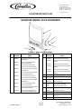
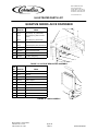
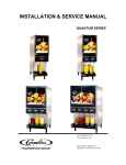
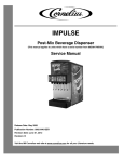
INSTALLATION & SERVICE MANUAL QUANTUM SERIES IMI CORNELIUS INC. www.cornelius.com Part Number- 720901120 Revision B - November 23, 2004 TABLE OF CONTENTS UNIT SPECIFICATIONS.................................................................... 1 PREINSTALLATION ...........................................................................2 Receiving ..............................................................................................................2 Unpacking ............................................................................................................. 2 Counter Location .................................................................................................. 2 installation specifications ............................................................... 3 Water Supply ........................................................................................................ 3 Electrical ................................................................................................................3 Space ................................................................................................................... 3 Connecting Water Supply .....................................................................................3 Filling Unit with Water ........................................................................................... 3 Flushing and Sanitizing on Start Up ..................................................................... 4 Programming Portion Control (optional) ...............................................................4 Cancel/Pour Button .............................................................................................. 4 Concentrate loading and brixing .................................................... 5 Placing Concentrate Products on Dispensing Platform........................................ 5 Changing Concentrate Flavor ............................................................................... 5 Pump Priming ....................................................................................................... 5 Brix Setting ........................................................................................................... 5 Cleaning and sanitizing procedures ............................................... 6 Daily: System Flush Procedure ............................................................................ Daily: Part Washing .............................................................................................. Weekly: Sanitizing Procedure............................................................................... Weekly: Check Brix Setting .................................................................................. Semi-Annual: General Cleaning ........................................................................... Yearly: Replace Pump Tubing.............................................................................. 6 6 6 7 7 7 Trouble-shooting guide ................................................................. 11 Quantum Series Installation and Service Manual UNIT SPECIFICATIONS Clearance Recommended: 12” (30.48 cm) on top and 4” (10.16 cm) required in back for air circulation if sides are blocked off. If sides are open only 2” (5.08) are required in back. Space between bottom of unit and counter cannot be obstructed in foot print area. Electrical Connection: 6ft. long (1.83m) power cord with 3-prong plug attached to dispenser. Export models have line cord less plug. Power Supply: 15 amps at 120 volts or 10 amps at 220 volts. Water Connection: 3/8” (0.95 cm) SAE male flare fitting on dispenser. Water Supply Requirements: 80 psi (5.5 bar) maximum static pressure. 20 psi (1.4 bar) minimum dynamic pressure; i.e., flowing pressure measured at dispenser water inlet with 3.0 ounces (88.7ml) per second water flow. -1- 720901120 Quantum Series Installation and Service Manual PREINSTALLATION RECEIVING Each unit is completely tested and inspected before shipment. At time of shipment, the carrier accepts the unit and any claim for damage must be made with the carrier. Upon receiving from the carrier, please, inspect the carton for visible damage. If damage exists, have the carrier make a note on the bill of lading and file a claim with the carrier. UNPACKING • • • • • • • Remove staples securing carton to pallet. Lift carton up and off of unit. Remove top insert and shipping bag. Open the upper cabinet door and remove installation kit. Remove bolts securing unit to pallet. Lift unit off of pallet. Open the package, take legs and secure them to the bottom of the unit. NOTE: Do not lay the unit on sides or on the back. • • Tilt the unit only when securing legs. If the unit is to be transported from the place where it was unpacked, do not remove the unit from the pallet. Transport it on the pallet to the installation site. COUNTER LOCATION • Select location in well ventilated area, close to grounded electrical outlet. If possible do not place the unit close to hot and/or steaming machines. 720901120 - 2- Quantum Series Installation and Service Manual INSTALLATION SPECIFICATIONS W ATER SUPPLY The Quantum Juice Dispensing machine is designed to dispense juice at a high flow rate. It is very important that the incoming water line is dedicated for the unit, or at least does not have other machines connected which could cause a water surge; i.e., a dishwashing machine. NOTE: For increased cooling capacity the unit should be connected to a remote recirculating cooling unit. If the location is equipped with a dedicated beverage water supply system the juice dispenser should be connected to it. NOTE: The water supply should be consistent with proper water quality standard (neutral ph of 7.0 to 8.0), and should not be connected to a water softener. The water cooling coil is Copper, and may be affected by poor water conditions (i.e. severe corrosion and pitting). Water connections shall be sized, installed, and maintained according to Federal, State, and Local Laws. ELECTRICAL A minimum of 15 amps electrical service is needed for 120V power supply or 10 amps for 220V supply. SPACE The minimum clearance is: 4” (10.16cm) in back and 12” (30.48cm) on top and open to the front if sides are blocked off. If the sides are open then only 2” (5.08cm) is required in the back. Space between the bottom of the unit and the counter cannot be obstructed. NOTE: Condenser air is drawn from the bottom and discharged out the back. Failure to maintain clearance space will reduce capacity of the unit and cause premature compressor failure. CONNECTING W ATER S UPPLY 1. Secure 3/8” (0.95cm) flexible hose to the unit water inlet. Make sure that the seal washer is used (hose and seal washer are included with the installation kit). 2. When securing flare nut use backup wrench on male side of the fitting (unit side) to prevent twisting of the copper tube inside the unit and/or possible damage to the water strainer/solenoid. A water shut off outside the unit is recommended. FILLING U NIT WITH W ATER To properly prime the unit with water, without air pockets in the system, push the dispensing switches simultaneously for a few seconds each. Repeat above until a steady flow of water is observed. NOTE: Water splashing may occur during the purge cycle. -3- 720901120 Quantum Series Installation and Service Manual FLUSHING AND SANITIZING ON START UP Follow standard sanitizing and flushing procedure. PROGRAMMING PORTION CONTROL ( OPTIONAL) The portion control supplied with your orange juice dispenser has been programmed to pour 7, 12, and 16 ounce drinks. The “XL” size has also been programmed to pour 16 ounces. Should pour size adjustments be required, please follow the instructions below: 1. Simultaneously, press and hold “S” (small) and “XL” (extra large) push button switches on the Portion Control Module until the led “REFILL” light in the corner of the module starts blinking. Release the switches. The blinking led indicates the programming mode is active. 2. Place the cup under the white mixing valve nozzle and push the selected size button (small, medium, large, or extra large). Hold the button in until the cup fills to the desired portion, then release the button repeat the above procedure for the remaining sizes. 3. After programming all the drink sizes, press and release the “cancel/pour” switch to return the Portion Control to the operational mode. The blinking led light will go out. If at a future date, it is decided to change the portion size of the drinks, the individual sizes can be adjusted by the above procedure. It is not necessary to reprogram every size. The portion control has a full memory retention in case of a power failure. CANCEL/POUR B UTTON • • Push and release the cancel/pour button to stop the valve from dispensing. Push and hold for a continuous pour. 720901120 - 4- Quantum Series Installation and Service Manual CONCENTRATE LOADING AND BRIXING PLACING C ONCENTRATE P RODUCTS ON D ISPENSING PLATFORM To engage the concentrate container, place it in the desired position and press down into bottle adapter opening on dispensing platform tray (inside the cabinet). NOTE: Make sure o-ring seal on the container adapter is lubricated; otherwise, you may experience difficulties with container replacement. NOTE: Concentrate in the containers must be completely thawed and be within the temperature range of 35°F - 40°F (1.6°C - 4.4°C). Failing to supply concentrate inside the recommended temperature range, especially below 35°F (1.6°C), will cause an out of brix drink. It is recommended the concentrate be thawed in a refrigerated (35°F - 40°F) (1.6°C - 4.4°C) compartment for 36 to 48 hours before use. It is recommended that the thawed concentrate be thoroughly shaken before use. CHANGING CONCENTRATE F LAVOR 1. Perform flush cycle 2. Move valve handle to “Dispense” position 3. Replace concentrate container PUMP PRIMING 1. Follow instructions in paragraph “Placing Concentrate Products on the Dispensing Platform” 2. Close the door (or unit will not activate) 3. Depress the push button until concentrate appears at the dispensing nozzle. BRIX SETTING 1. Make two (2) full clockwise turns of the corresponding brix knob from the “all the way out” position (factory set). These two turns will bring you within one turn of proper brix setting. (Refer to brix table located on the inside of the refrigerated compartment door). 2. Dispense 1/2 cup of juice and discard. 3. Dispense 1/2 cup of juice and use refractometer to check brix level. 4. Clockwise rotation of the knob decreases brix level for example from 13% to 11.5%. Counterclockwise will increase brix level for example from 11.5% to 13%. If a brix problem is experienced, refer to troubleshooting guide. -5- 720901120 Quantum Series Installation and Service Manual CLEANING AND SANITIZING PROCEDURES DAILY: S YSTEM F LUSH P ROCEDURE 1. A 1 quart (0.95 liters) (32 fluid oz. minimum) empty container is needed. Place the empty container on the drip tray grill under the nozzle of the dispensing station to be flushed. 2. Open the cabinet door. 3. Choose the valve handle that corresponds with dispensing station to be flushed. 4. Move chosen handle from “dispense” position to the “flush” position. 5. Close the door. 6. Depress and hold push button corresponding with dispensing station to be flushed, until clear water is dispensed from the nozzle. 7. Move the handle to the “dispense” position. 8. Depress the push button for approximately 0.5 sec. and release. This will release water pressure from the pump system. It is recommended to use one or more quarts of water to flush a single dispensing station. DAILY: P ART W ASHING 1. Remove and wash dispensing nozzle, static mixer, splash plate, drip pan, bracket, and grille in a mild detergent solution. Rinse thoroughly. W EEKLY: S ANITIZING P ROCEDURE 1. Remove juice concentrate container from unit and place in separate refrigerated compartment. 2. Perform flush procedure. 3. Fill a clean empty concentrate container with one quart of extremely hot tap water, approximately 140°F (60°C) and place into unit. Run the hot water completely through unit into a large container. When complete remove concentrate container. 4. Remove nozzles and static mixers from unit and rinse under hot tap water to remove excess pulp. 5. Place nozzles and static mixers in separate container with 1 quart (0.95 liter) of sanitizing solution and agitate vigorously, using brush (P/N 07932) to remove any excess pulp or concentrate (allow to soak for 2 minutes). 6. Clean bottle adaptor’s inlet area along with dispensing platform tray with brush and sanitizing solution to remove concentrate and pulp. 7. Clean valve mixing chambers with brush and sanitizing solution. (This is the cavity from which the nozzle is removed). 8. Replace nozzles and static mixers into proper location. 720901120 - 6- Quantum Series Installation and Service Manual 9. Fill a clean empty concentrate container with 2 quarts (1.9 liters) of sanitizing solution, place on dispensing platform, and insert bottle fitting into bottle adapter. NOTE: Do not reuse the same sanitizing solution used to clean nozzles, static mixers, etc. 10. Place handle in dispense position and close door. 11. Run dispensing station for 90 seconds then stop; allow sanitizing solution to remain in lines for 5 minutes. 12. Dispense remaining sanitizing solution (approximately 90 seconds). 13. Replace sanitizing solution container with a concentrate container, and close door. 14. Depress and hold push buttons until juice appears at outlet of dispensing nozzle. 15. Dispense and discard two 8 oz. cups (236.6 ML) of juice. NOTE: Wipe internal and external surfaces of cabinet with a clean damp cloth. W EEKLY: C HECK BRIX SETTING Tools: Hydrometer or Refractometer 1. Dispense required ounces of juice per brix testing device instructions. 2. Test concentrate to water ratio of dispensed juice per brix testing device instructions. 3. Clockwise rotation of knob decreases brix level (i.e. from 13% to 11.5%). Counterclockwise rotation of knob increases brix level (i.e. from 11.5% to 13%). NOTE: If brix problem persists, refer to trouble shooting guide. SEMI-A NNUAL: G ENERAL C LEANING 1. Remove access port of Y-shaped water solenoid located on water inlet in lower cabinet, clean stainless steel strainer and reinstall. 2. Clean condenser fins. 3. Clean air inlet grille located in base of unit. 4. Clean lower cabinet interior. 5. Wipe fan blade clean. YEARLY: R EPLACE P UMP T UBING Removal of Platform (see figure 1): 1. Remove concentrate container from the dispenser and place in a refrigerator. 2. Remove the product shelf. 3. Depress the button on the water line quick disconnect and lift the water line away from the platform. 4. Unplug the platform electrical connector at the inside rear of the cabinet. 5. Release the catch at the front of the platform by pulling the tab towards yourself with on finger. -7- 720901120 Quantum Series Installation and Service Manual 6. Remove the nozzle and static mixers. 7. Carefully lift and pull the platform from the dispenser and place it in a clean and well lit area for service. Replacement of Pump Hose (see figure 2): 1. Remove platform as described above in removal of platform instructions. 2. Remove the two white plastic hose clamps from the pump tube connections. Remove the two stainless steel concentrate delivery tubes from the hose ends. 3. Loosen and remove the four thumb screws from the pump body. 4. Remove the rear half (only) of the pump body to reveal the hose and rollers. 5. Remove the old hose from the pump body. If the rollers come out with the hose, place in back into the housing being sure to align the roller assembly shaft keyway to the motor shaft key so that the two interlock (see figure 3 for step by step pictorial instructions). 6. Firmly press the new hose into the pump body around the roller assembly, being sure to keep the protruding ends even with each other. Once the hose is in place, replace the outer half of the pump body. Hold the tubing in place inside pump housing with one hand, capture the lower part of the tubing with the outer housing, then proceed to capture the shaft of the roller assembly and push the housing straight onto the pump/motor portion of the assembly. Make sure to capture the hose within the body and not pinch it between the halves. Do not use any tool other than your finger tips to manipulate the hose into the housing or damage to the hose will result. 7. While holding the pump halves together by hand, reinsert the four thumb screws and tighten them in a criss-cross pattern until the two halves are pressed together. 8. Insert the two stainless tubes into the hose ends and fasten them with new clamps using pliers to tighten the clamps. Replace platform in unit, reinstall nozzles and static mixers, connect water, install product shelf and concentrate, and reconnect power to unit. 720901120 - 8- Quantum Series Installation and Service Manual -9- 720901120 Quantum Series Installation and Service Manual 720901120 - 10 - Quantum Series Installation and Service Manual TROUBLE-SHOOTING GUIDE The following pages contain trouble-shooting charts designed to aid an experienced serviceman in diagnosing any operating problems that may be experienced. In order to gain maximum benefit from the charts, please note: 1. Start at the beginning of the chart and supply the appropriate answer to each question. 2. Do not skip any section, unless instructed to do so. You may miss the solution to your problem. 3. Evaluate the possible problem causes in the sequence in which they are presented. In general, they began with the most likely and/or easiest to check, and proceed to the less likely and/or more complicated. 4. If, after checking all indicated causes, the problem is not resolved, it is recommended that you try a second time. Evaluate symptoms carefully and modify your answers as necessary. 5. If you are unable to resolve a problem after several attempts, contact customer service department at (1-800-238-3600) for assistance. PROBLEM Totally Inoperative No cooling PROBABLE CAUSE REMEDY No power to dispenser due to tripped circuit breaker. Reset circuit breaker. Confirm that breaker is correct size and no other equipment is operating on the same circuit. Also confirm that supply voltage is +10% of nameplate specifications. Loose or broken power supply connection inside dispenser. Repair connection Line voltage is not within +10% of nameplate specifications causing compressor overload to trip Contact an electrician Both thermostats in OFF position Turn ON thermostats and recalibrate the temperatures to 34 o F -40 o F (1.1 o C –4.5 o C). Defective compressor overload or start capacitor - 11 - Replace 720901120 Quantum Series Installation and Service Manual No cooling (con’t) No water dispensed, concentrate only. 720901120 Defective start relay located on upper rear shelf inside dispenser There should be line voltage on the black wire of the relay when there is line voltage present on the orange OR yellow wire. Replace relay if it fails this test. Compressor starts but hums and trips overload Seized or shorted compressor, replace. Compressor starts but does not switch off of start winding Relay or compressor is defective. Test and replace faulty item. Compressor short cycles on overload Excessively high discharge pressure due to restricted condenser or inoperative condenser fan motor Refrigerant leak Repair leak. Evacuate and recharge system. No water to dispenser Restore water Water supply line inside refrigerated cabinet disconnected from pump platform Reconnect Water solenoid located on pump platform clogged or defective Disassemble and clean solenoid. Replace if necessary. Main water solenoid/ strainer located at base of dispenser is clogged, binding or defective Remove and clean strainer. Confirm 28VDC is present at solenoid during dispense. Confirm solenoid coil is not open. Disassemble and clean solenoid. Water supply pressure is greater than 80 psi (5.5 bar) Add external regulator and lower pressure to 50 psi (3.5 bar) - 12 - Quantum Series Installation and Service Manual No water dispensed, concentrate only (con’t). Freeze-up of water coil or concentrate chamber Unplug dispenser and allow 2-4 hours to thaw. Water or concentrate thermostat set too low, recalibrate to 34oF -40 oF (1.1 oC - 4.5 o C). Defective water or concentrate thermostat, replace. Refrigerant solenoid stuck open or not closing fully. Evacuate system, replace solenoid valve and recharge No water and no concentrate, refrigeration is working No water and no concentrate, refrigeration is working Service switch located under drip tray in OFF position Turn on switch Door switch open Door switch must be closed in order to operate pump. Check switch operation and replace if necessary 6.25 amp Fuse inside front electrical box blown Replace with 6.25 amp, 250VAC slow blow fuse and test No output from Transformer located on rear upper shelf Confirm transformer output by measuring for 26VAC at fuse. Replace transformer if necessary Defective voltage regulator board (VRB) located inside front electrical box Measure across the blue and black wire located in the upper left corner of the board. There should be 28VDC present when the dispense button is pressed. Replace VRB if necessary Defective portion control board Disconnect wire harness from rear of portion control, close door switch and short the orange and black wires together on the harness. If unit dispenses portion control board is defective. If it does not dispense the voltage regulator board is defective. - 13 - 720901120 Quantum Series Installation and Service Manual No concentrate dispensed, water only Excessive remnant left in empty concentrate pouch Concentrate refill light comes on prematurely Concentrate refill light does not come on at all 720901120 Dispense tube not fully engaged into receptacle on concentrate pouch Refer to Concentrate Loading section of this manual Dispense tube disconnected from mixing chamber Refer to Concentrate Loading section of this manual Slide block on pump in open position Close and lock the slide block. Refer to Concentrate Loading section of this manual Switch on pump platform in FLUSH position Move switch to RUN position Concentrate too cold, not properly thawed Concentrate should be 34o F -40 o F Defective pump motor Replace pump motor Concentrate pouch improperly thawed Concentrate should be 34o F -40 o F Concentrate pouch and/or dispense tube improperly installed Refer to Concentrate Loading section of this manual Concentrate pouch improperly thawed Concentrate should be 34o F -40 o F Concentrate pouch and/or dispense tube improperly installed Refer to concentrate loading section of this manual Loose wiring Check wiring connections between the pump motor and the VRB board Bad VRB board Replace VRB board Bad pump motor Replace pump motor Pump improperly locked or pump is open Close and lock Pump Run/flush switch is in the FLUSH position Move switch to the RUN position - 14 - (1.1 o C –4.5 o C) prior to loading (1.1 o C –4.5 o C) prior to loading (1.1 o C –4.5 o C) prior to loading. Quantum Series Installation and Service Manual Concentrate refill light does not come on at all (con’t) Improperly loaded tube Refer to concentrate loading section of this manual Bad VRB board Replace VRB board Bad portion control Replace portion control Incoming water supply too warm Optimum performance is achieved when the dispenser utilizes water from a pre-cooler Ambient air too warm Relocate dispenser Excessive demand on dispenser Add water pre-cooler or second dispenser Dirty condenser coil Clean condenser coil Inoperative condenser fan Replace condenser fan motor Defective water thermostat Replace thermostat Loss of refrigerant charge due to leak in system Repair leak and recharge system Water continuously drips from nozzle when in OFF mode Main water solenoid at base of unit or water solenoid on pump platform not shutting off tightly Clean solenoid(s), replace parts as necessary No Flush Cycle Run/Flush switch on pump platform in Run mode Move switch to Flush position Defective Run/Flush switch on pump platform (concentrate continues to dispense while in Flush mode) Replace Run/Flush switch Concentrate thermostat is turned off or not calibrated properly Calibrate to be 34o F -40 o F (1.1 o C Concentrate thermostat defective (stuck open) Replace thermostat and calibrate Defective start relay located on upper rear shelf inside dispenser There should be line voltage on the black wire of the relay when there is line voltage present on the orange OR yellow wire. Replace relay if it fails this test. Warm Drink Concentrate warm, water cold - 15 - –4.5 o C) to 34 o F -40 o F (1.1 o C –4.5 oC) 720901120 Quantum Series Installation and Service Manual Concentrate warm, water cold (con’t) Loss of refrigerant charge due to leak in system Repair leak and recharge system Brix Problem Water supply pressure too low, less than 20 psi (1.4 bar) flowing or water pressure fluctuates sharply Correct water supply problem to ensure a constant 40 psi (3 bar) flowing to the dispenser Water flow control binding or spring is defective Clean and/or replace parts as necessary Improperly thawed concentrate. Brix changes as the concentrate temperature changes (concentrate becomes thinner as temperature rises) Concentrate should 34 o F -40 o F Check that the rollers on the pump are spinning freely with no tube in place If they are sticky or locked up see platform removal and cleaning procedure. Pump motor defective 28VDC should be present at pump motor during dispense. If voltage is present and motor does not start, replace pump motor No power to transformer or no 28VAC output from transformer Confirm transformer has line voltage present on primary side. If no 28VAC output from the secondary replace transformer Defective voltage regulator board (VRB) located inside front electrical box Measure across the blue and black wire located in the upper left corner of the board. There should be 28VDC present when the dispense button is pressed. Replace VRB if necessary Defective portion control board Disconnect wire harness from rear of portion control, close door switch and short the orange and black wires together on the harness. If unit dispenses portion control board is defective. If it does not dispense the voltage regulator board is defective. Pump Inoperative 720901120 - 16 - (1.1 o C –4.5 o C) prior to loading Quantum Series Installation and Service Manual Machine continues to dispense after dispense button is released or dispenses without operator input Sold Out light illuminates when concentrate no longer passes through the pump. Portion control pad stuck in on position Disconnect the wire harness from the rear of the portion control and close the door. If unit does not dispense on its own the portion control is bad (stuck on) Relay on voltage regulator board (VRB) stuck on. Disconnect the 4-wire harness from the lower right corner of the VRB. If the unit continues to dispense on its own the VRB is defective (relay stuck on) The concentrate is improperly thawed. The temperature is not maintained between 34×F - 40×F(1.1-4.5×C) Assure proper thawing procedures have been followed per the Minute Maid company instructions. Check that McDonald’s walk-in cooler temperature is on the proper set point. Check the dispenser cabinet temperature is at 34×F - 40×F(1.14.5×C). High Brix readings result in a poor, pulsating/splashing dispense, erratic pump amp draw, and consequently erratic sold-out indications. - 17 - Check drink brix in procedure described on equipment P.M. card using the hydrometer provided. Check the drink flow rate under normal operating conditions. The dispenser should pour a drink at a flow rate of approximately 1.5 oz. Per second or greater. If the flow rate is less, a check described in the Sold Out section should be completed. 720901120 Quantum Series Installation and Service Manual Sold Out light illuminates when concentrate no longer passes through the pump.(con’t) Improper loading procedures will usually result in low brix conditions and thus erratic sold out indications. Check that the pouch of juice is properly loaded in the pouch holder. Tube fitting should be located at the bottom of the pouch holder and the tube should be approximately centered in the bottom portion of the opening of the holder. Check that the tube is correctly loaded in the pump and the pump is fully locked (top and bottom slide pins should be fully engaged into the pump body). Sold Out light fails to reset itself after door is opened and closed (Sold Out light stays illuminated) 720901120 Tube has been stretched through pump when it was loaded. Pouch may not be seated correctly. Adjust pouch. If pouch is loaded correctly there should be ample tube to reach the mixing chambers without stretching the tube. Check that the rollers on the pump are spinning freely with no tube in place. If the rollers are sticky or locked up see the platform removal and cleaning procedure. Check the operation of the reset switch located at the bottom left hand side of the door. Adjust Switch. - 18 - IMI Cornelius Inc. One Cornelius Place Anoka, MN 55303-1592 U.S.A. Total Systems Commitment IMI CORNELIUS INC. One Cornelius Place Anoka, MN. 55303–6234 Telephone 1-800-238-3600 Facsimile 1-800-258-0255 www.cornelius.com ILLUSTRATED PARTS LIST QUANTUM SERIES JUICE DISPENSER MODEL NO. 45200001 45200002 45200003 45200004 45200101 45200102 45200103 45200104 45400001 45400002 45400101 45400102 45400103 45400104 45500001 45500002 45500101 45500102 45650001 45650003 45650101 45650103 45650104 45650105 QUANTUM SERIES 1 of 16 Rev A Manual Part No. 720901120IPL 4-25-2001 Rev: 12-3-01 IMI Cornelius Co., 2001 IMI CORNELIUS INC. One Cornelius Place Anoka, MN. 55303–6234 Telephone 1-800-238-3600 Facsimile 1-800-258-0255 www.cornelius.com ILLUSTRATED PARTS LIST QUANTUM SERIES JUICE DISPENSER 3 29 36 2 20 41 13 31 17 11 27 42 39 28 12 22 4 36 30 35 16 14 21 34 32 36 9 39 25 41 41 2 6 2 3 3 38 36 23 37 15 1 40 10 8 7 36 19 33 36 24 26 36 36 5 35 18 36 FIGURE 1. GENERAL ASSEMBLY Manual Part No. 720901120IPL 4-25-2001 Rev: 12-3-01 IMI Cornelius Co., 2001 2 of 16 Rev A QUANTUM SERIES IMI CORNELIUS INC. One Cornelius Place Anoka, MN. 55303–6234 Telephone 1-800-238-3600 Facsimile 1-800-258-0255 www.cornelius.com ILLUSTRATED PARTS LIST QUANTUM SERIES JUICE DISPENSER Item No. 1 2 3 Part No. 0720405 0730202 0706903 07061002 4 5 07344 45366 6 7 0733904 45107 8 9 10 11 12 7245669 45408 45159001 45667100 45459100 45003 31525037 45123 48808001 470725 45354 45241 45390 45470 7245550 45296006 45394005 45481006 13 14 15 16 17 309852000 77060900 49034 45439 45115 45215 45215001 45315 18 45129001 45129100 45678100 45430100 QUANTUM SERIES Item No. Name Nut 1/4-20 Washer No. 10 Split Lock Screw No. 10-32 x 1/2” TH SS 115V 60HZ Screw No. 10 x 5/8” HHWF 230V 50HZ Bushing Snap 3000 and 4000 Series Brkt and Tube Drain 3000 and 4000 Series Bushing Snap Cover Elec Box 1000 and 2000 Series Cover Elec Box 3000 Series Cover Elec Box 4000 Series Panel Splash 1000 and 2000 Series Panel Splash 3000 Series Panel Splash 4000 Series Nozzle Mixer O-Ring Asy O-Ring .739 I.D. Mixer Static Nozzle Mixing Plug Butn DoorAsy 1000 Series(SeeFigure8) DoorAsy 2000 Series(SeeFigure8) DoorAsy 3000 Series(SeeFigure8) DoorAsy 4000 Series(SeeFigure8) Cover Asy 1000 Series (See Figure 10) Cover Asy 2000 Series (See Figure 10) Cover Asy 3000 Series (See Figure 10) Cover Asy 4000 Series (See Figure 10) Clamp 1000, 2000 and 3000 Series Fitg T-Brb 3/8 1000, 2000 and 3000 Series Tube 1000, 2000 and 3000 Series Washer Nylon Refrigeration Asy (See Figure 2) Cabinet Asy (See Figure 3) Platform Asy 1000 Series (See Figure 4) Platform Asy 115V 60HZ, 2000 and 4000 Series (See Figure 4) Platform Asy 230V 50HZ, 2000 and 4000 Series (See Figure 4) Platform Asy 115V 60HZ, 3000 Series (See Figure 4) Drip Tray, 1000 Series Drip Tray, 2000 Series Drip Tray, 3000 Series Drip Tray, 4000 Series 3 of 16 Rev A 19 20 21 22 23 24 Part No. 45155001 45255003 45677003 45455003 45158 45117 45317 45417 45444 45151 45666 45451 46546 45152 25 96561 45436 26 27 28 29 30 31 32 7245443 49154 45165100 49155 309852000 49157 45199 45659 45445 45125 7245665 45425 7245765 7245763 7245764 07115001 0704106 45088 45087 0702901 45164 45032 45464 0730104 0720406 33 34 35 36 37 38 39 40 41 42 43 Name Cup Rest, 1000 Series Cup Rest, 2000 Series Cup Rest, 3000 Series Cup Rest, 4000 Series Shelf, 1000 Series Shelf, 2000 Series Shelf, 3000 Series Shelf, 4000 Series Strap Electrical Box Asy (See Figure 12) Brkt Water Coil 1000 and 2000 Series Brkt Water Coil 3000 Series Brkt Water Coil 4000 Series Arm Asy Brkt Asy Drip Tray 1000 Series (Not Shown) Plate Door Support 1000 Series Plate Door Support 2000, 3000 and 4000 Series Panel RH Side Plate Hinge Upper Coil Wtr Asy Hinge Bolt Shoulder Clamp Bushing Upper Hinge Panel Top 1000 and 2000 Series Panel Top 3000 Series Panel Top 4000 Series Panel Back 1000 and 2000 Series Panel Back 3000 Series Panel Back 4000 Series Brkt Cabinet 1000 and 2000 Series Brkt Cabinet 3000 Series Brkt Cabinet 4000 Series Screw TF 08-32 TRPH 12 Screw 8-32 x 1/4” THMS Cover Botm Hinge Cover Top Hinge Screw 8-32 x 3/8” FHM Brkt Flavor Strip 2000 Series Holder Flavor Label 3000 Series Holder Flavor Label 4000 Series Washer Plain Flat 10 Nut No. 10-32 Item Not Used Manual Part No. 720901120IPL 4-25-2001 Rev: 12-3-01 IMI Cornelius Co., 2001 IMI CORNELIUS INC. One Cornelius Place Anoka, MN. 55303–6234 Telephone 1-800-238-3600 Facsimile 1-800-258-0255 www.cornelius.com ILLUSTRATED PARTS LIST QUANTUM SERIES JUICE DISPENSER 11 1 10 9 2 8 7 3 5 6 4 15 19 20 21 13 12 14 16 17 18 22 FIGURE 2. REFRIGERATION AND FRAME ASSEMBLY Manual Part No. 720901120IPL 4-25-2001 Rev: 12-3-01 IMI Cornelius Co., 2001 4 of 16 Rev A QUANTUM SERIES IMI CORNELIUS INC. One Cornelius Place Anoka, MN. 55303–6234 Telephone 1-800-238-3600 Facsimile 1-800-258-0255 www.cornelius.com ILLUSTRATED PARTS LIST QUANTUM SERIES JUICE DISPENSER (SEE FIGURE 2) Item No. Part No. Name Item No. Refrigeration and Frame Ass’y 1 10 729011105 Kit Compressor, 120V 60HZ 729011106 Kit Compressor, 230V 50HZ 11 2 08474 Clip Spring 12 3 07301046 4 5 Part No. Name 45373010 Solenoid Valve 120V 60HZ 45373020 Solenoid Valve 230V 50/60HZ Box Elec Asy (See Figure 11) 45105100 Frame (1000 and 2000 Series) Washer Ft .468 I.D. 45671100 Frame (3000 Series) 08467 Grommet Compressor 45405100 Frame (4000 Series) 45163001 Mtr Asy and Cond 115V 60HZ (See Figure 9) 13 07115001 Screw TF 08-32 TRPH 12 14 60342002 Insert Thd 3/8-16 45163002 Mtr Asy and Cond 230V 50/60HZ (See Figure 9) 15 2124713 Fitg Stght 3/8MF x 3/8MPT 6 7240691 Grommet 16 45091001 Valve Water Solenoid 24V 7 45148 Baffle Cond (1000 and 2000 Series) 17 03824001 Nut Jam 7/8-14 45670 Panel Baffle Cond (3000 Series) 18 30041001 Fitg Bulkhead 45448 Panel Baffle Cond (4000 Series) 19 04442 Spacer 8 289521 Screw No. 8-32 xy 3/8” HHS 20 0702609 Screw MA 8-32 BDPH 24 9 45073 Dryer 21 7221320 Strain Relief 22 46384 Cord Serv 115V 60HZ 46384001 Cord Serv 220V 50HZ QUANTUM SERIES 5 of 16 Rev A Manual Part No. 720901120IPL 4-25-2001 Rev: 12-3-01 IMI Cornelius Co., 2001 IMI CORNELIUS INC. One Cornelius Place Anoka, MN. 55303–6234 Telephone 1-800-238-3600 Facsimile 1-800-258-0255 www.cornelius.com ILLUSTRATED PARTS LIST QUANTUM SERIES JUICE DISPENSER 3 5 16 12 2 14 11 13 1 10 4 15 9 6 8 FIGURE 3. UPPER CABINET ASSEMBLY Manual Part No. 720901120IPL 4-25-2001 Rev: 12-3-01 IMI Cornelius Co., 2001 6 of 16 Rev A QUANTUM SERIES IMI CORNELIUS INC. One Cornelius Place Anoka, MN. 55303–6234 Telephone 1-800-238-3600 Facsimile 1-800-258-0255 www.cornelius.com ILLUSTRATED PARTS LIST QUANTUM SERIES JUICE DISPENSER (SEE FIGURE 3) Item No. Part No. Name 45027001 Bushing 7 11761 Harn Door (1000 Series: Not Shown) 11762 Harn Door (2000 Series: Not Shown) 11763 Harn Door (3000 Series: Not Shown) 11823 Harn Door (4000 Series: Not Shown) Stud Latch No. 10-32 2 45119 Gasket Liner (1000 and 2000 Series) 5 Name 6 45051 4 Part No. Upper Cabinet Asy 1 3 Item No. 45662 Gasket Liner (3000 Series) 45419 Gasket Liner (4000 Series) 45141 Wrap Front (1000 and 2000 Series) 45657 Wrap Front (3000 Series) 45441 Wrap Front (4000 Series) 8 0704105 Screw No. 8-32 x 1/2” THMS 45142 Panel Botm Front (1000 Series) 9 0704101 Screw MA No. 8-32 TRPH 12 45207 Panel Botm Front (2000 Series) 10 04441 Spacer Lower 45664 Panel Botm Front (3000 Series) 11 0702609 Screw MA No. 8-32 BDPH 24 45407 Panel Botm Front (4000 Series) 12 46366 Bushing Hinge 45167 Liner Inner Asy (1000 Series) 13 45132 Brkt Conn Platform (1000 Series) 45220 Liner Inner Asy (2000 Series) 45232 Brkt Conn Platform (2000 and 4000 Series) 45654100 Liner Inner Asy (3000 Series) 45632 Brkt Conn Platform (3000 Series) 45420100 Liner Inner Asy (4000 Series) 14 0704001 Screw No. 8 x 3/8” 15 47121004 Magnet Door Seal 16 47121005 Magnet Door Seal (1000 and 2000 Series) 47121006 Magnet Door Seal (3000 Series) QUANTUM SERIES 7 of 16 Rev A Manual Part No. 720901120IPL 4-25-2001 Rev: 12-3-01 IMI Cornelius Co., 2001 IMI CORNELIUS INC. One Cornelius Place Anoka, MN. 55303–6234 Telephone 1-800-238-3600 Facsimile 1-800-258-0255 www.cornelius.com ILLUSTRATED PARTS LIST QUANTUM SERIES JUICE DISPENSER 27 7 19 21 25 2 22 20 27 23 26 24 18 12 4 6 9 27 11 8 10 27 1 3 16 17 15 5 13 14 18 27 28 FIGURE 4. PLATFORM ASSEMBLY Manual Part No. 720901120IPL 4-25-2001 Rev: 12-3-01 IMI Cornelius Co., 2001 8 of 16 Rev A QUANTUM SERIES IMI CORNELIUS INC. One Cornelius Place Anoka, MN. 55303–6234 Telephone 1-800-238-3600 Facsimile 1-800-258-0255 www.cornelius.com ILLUSTRATED PARTS LIST QUANTUM SERIES JUICE DISPENSER (SEE FIGURE 4) Item No. Part No. Name Item No. Part No. Name 45115 Platform Asy (1000 Series) 14 45047 Guide Latch 45215 Platform Asy (2000 and 4000 Series) 15 45048 Washer Latch 16 720800077 Rivet Latch 45315 Platform Asy (3000 Series) 17 45114 Platform (1000 Series) 1 0704101 Screw MA 8-32 TRPH 12 45214 Platform (2000 and 4000 Series) 2 71822081 Washer Holdown 45314 Platform (3000 Series) 3 309852000 Clamp 18 07032001 Screw No. 8-18 x 7/16” 4 45026 Adapter Bottle Asy (See Figure 5) 19 45173 Tube Asy Suction (1000 Series) 5 45033 Support Bottle Right 45276 6 45034 Support Bottle Left Tube Asy Suction (2000 and 4000 Series) 7 45391001 Adapter Caddy Support (1000 Series) 45068003 Tube Asy Suction (3000 Series) 45069 45391002 Adapter Caddy Support (2000 and 4000 Series) Line Discharge Asy (1000 and 3000 Series) 45273 45391003 Adapter Caddy Support (3000 Series) Tube Asy Discharge (2000 and 4000 Series) 45160 Brkt Botl Adapter (1000 Series) 45137 Panel Splash Platform (1000 Series) 7245262 45236 Panel Splash Valves (2000 and 4000 Series) Brkt Support Botl Adap (2000 and 4000 Series) 45339 Brkt Caddy Support (3000 Series) 45345004 Cover Platform (2000 and 4000 Series) 22 398033000 O-Ring .239 I.D. 7245036 Panel Splash Valves (3000 Series) 23 48195006 Clamp Hose 45345003 Cover Platform (3000 Series) 24 481950062 Clamp 9 45185 Pump and Mtr Asy (See Figure 7) 25 45275 Tube Asy Discharge (2000 and 4000 Series) 10 7245174 Manifold Asy Water (1000 Series) 26 45068001 Line Suct Asy (3000 Series) 45274 Manifold Asy Water (2000 and 4000 Series) 45277 Tube Asy Suction (2000 and 4000 Series) 45041 Manifold Asy Water (3000 Series) 45068002 11 45283 Bushing Tube Asy Center Suction (3000 Series) 12 45045 Block Valve Asy 27 0704001 Screw No. 8-x 3/8” 13 45046 Latch 28 0704105 Screw No. 8-32 x 1/2” THMS 8 QUANTUM SERIES 20 21 9 of 16 Rev A Manual Part No. 720901120IPL 4-25-2001 Rev: 12-3-01 IMI Cornelius Co., 2001 IMI CORNELIUS INC. One Cornelius Place Anoka, MN. 55303–6234 Telephone 1-800-238-3600 Facsimile 1-800-258-0255 www.cornelius.com ILLUSTRATED PARTS LIST QUANTUM SERIES JUICE DISPENSER 13 7 28 5 23 4 9 12 27 6 3 22 10 21 20 2 24 25 26 23 8 23 28 11 15 16 19 1 17 14 18 23 FIGURE 5. VALVE BLOCK ASSEMBLY Item No. Part No. Name Item No. Part No. Name 45045 Block Valve Asy 15 45180 Spring Acutuator 1 45177 Holder Poppet Seal 16 45189 Poppet 2 0720406 Nut No. 10-32 17 45179 Support Diaphram 3 71815321 Ring Retaining 18 45195 Plate Front Valve Block 4 7215323 Armature 19 45186 Spring 5 18070002 Gasket Rubber Valve Block 20 48520001 Coil Asy 24V DC 6 18367 Spring Armature 21 48978 Flo Cntl Bonnet Asy 7 19695001 Guide 22 48979103 Sleeve and Piston Asy Water 8 31525021 O-Ring 1.114 I.D. 60281001 Sleeve Syrup Ceramic 9 18071 Seat Armature 23 07032001 Screw No 8-18 x 7/16 10 48258005 Spring Syrup 24 16779003 Frame Solenoid 11 45192 Valve Body Mixing 25 49612 Port Valve Water 12 45193 Valve Body Water 26 31525020 O-Ring .176 I.D. 13 45029 Plate Coil Retainer 27 31525060 O-Ring .459 I.D. 14 47011 Diaph Valve 28 48378 Brkt Support Valve Manual Part No. 720901120IPL 4-25-2001 Rev: 12-3-01 IMI Cornelius Co., 2001 10 of 16 Rev A QUANTUM SERIES IMI CORNELIUS INC. One Cornelius Place Anoka, MN. 55303–6234 Telephone 1-800-238-3600 Facsimile 1-800-258-0255 www.cornelius.com ILLUSTRATED PARTS LIST QUANTUM SERIES JUICE DISPENSER Item No. 11 Part No. Name 1 45026 Adapter Bottle Asy 1 45060001 Adapter Caddy Top 2 45060002 Adapter Caddy Run and Flush 3 45060003 Adapter Caddy Bottom 4 31525062 O-Ring .118 I.D. 5 31525014 O-Ring .489 I.D. 6 31525061 O-Ring 1.489 I.D. 7 07015001 Screw No. 8-18 x 3/4” 8 45043 Pin Sensor Soldout 9 31525064 O-Ring .488 I.D. 10 60068021 Switch Snap Portion Control 11 45076 Pin Actuator 12 60067086 Screw No. 2-56 x 7/16” 13 45084001 Plate Support Bottle 8 12 5 10 6 2 9 6 4 3 7 13 FIGURE 6. BOTTLE ADAPTER ASSEMBLY 6 5 3 1 7 2 7 4 8 FIGURE 7. PUMP AND MOTOR ASSEMBLY Item No. Part No. Name 45185 Pump and Motor Asy 1 45016001 Motor Pump 2 45728001 Rotor Asy 3 45050 Block Asy Mtg Pump and Motor 4 45017001 Screw Thumb Pump 5 0702905 Screw No. 8-32 x 3/4” FHMS QUANTUM SERIES Item No. 11 of 16 Rev A Part No. Name 6 45037001 Tubg Neoprene .250 I.D. (Sold by the Foot) 7 45727 Body Pump Asy 8 45283 Bushing 9 45098 Kit Pump Tube Replacement Manual Part No. 720901120IPL 4-25-2001 Rev: 12-3-01 IMI Cornelius Co., 2001 IMI CORNELIUS INC. One Cornelius Place Anoka, MN. 55303–6234 Telephone 1-800-238-3600 Facsimile 1-800-258-0255 www.cornelius.com ILLUSTRATED PARTS LIST QUANTUM SERIES JUICE DISPENSER Item No. Part No. 45241 45390 Name 4 Door Asy Back (1000 and 2000 Series) Door Asy Back (3000 Series) 3 45470 Door Asy Back (4000 Series) 1 45281 Panel Rear Door (1000 and 2000 Series) 2 45386 Panel Rear Door (3000 Series) 45477 Panel Rear Door (4000 Series) 2 7233023 Switch Safety 3 7245120 Gasket Door Mag (1000 and 2000 Series) 45320 Gasket Door Mag (3000 Series) 45431 Gasket Door Mag (4000 Series) 7245780 Frame Door Gasket (1000 and 2000 Series) 7245781 Frame Door Gasket (3000 Series) 7245782 Frame Door Gasket (4000 Series) 5 7245779 Rivet .236 Dia. 6 45432 Switch Rocker 1 4 5 6 FIGURE 8. REAR DOOR ASSEMBLY Item No. 1 Part No. Name 45175001 Motor Asy Fan 9W 120V 60HZ 45175002 Motor Asy Fan 9W 230V 50/60HZ 0726802 Nut Tinnerman 2 45159 Panel Splash 3 41757 Washer 4 48004 Motor Fan 9W 120V 60HZ 48013 Motor Fan 9W 230V 50/60HZ 5 45168 Blade Fan 6 96285001 Screw No. 8-36 x 3/8” 7 45161 Cond Coil 1 3 2 7 5 4 6 FIGURE 9. CODENSER MOTOR ASSEMBLY Manual Part No. 720901120IPL 4-25-2001 Rev: 12-3-01 IMI Cornelius Co., 2001 12 of 16 Rev A QUANTUM SERIES IMI CORNELIUS INC. One Cornelius Place Anoka, MN. 55303–6234 Telephone 1-800-238-3600 Facsimile 1-800-258-0255 www.cornelius.com ILLUSTRATED PARTS LIST QUANTUM SERIES JUICE DISPENSER 1 4 9 3 6 2 5 7 FIGURE 10. DOOR COVER ASSEMBLY Item No. Part No. Name 45296006 Cover Asy Merchndsr Push Button (2000 Series) 45296007 Cover Asy Merchndsr Portion Control (2000 Series) 45296009 Cover Asy Merchndsr Portion Control, Illuminated (2000 Series) 45394005 Cover Asy Merchndsr Push Button (3000 Series) 45394007 Cover Asy Merchndsr Push Button, Illuminated (3000 Series) 45394008 Cover Asy Merchndsr Portion Control, Illuminated (3000 Series) Item No. 1 Cover Merchndsr (2000 Series) 45224005 Cover Merchndsr Illuminated (2000 Series) 45377004 Cover Merchndsr (3000 Series) 45377005 Cover Merchndsr Illuminated (3000 Series) 45472004 Cover Merchndsr (4000 Series) 45472005 Cover Merchndsr Illuminated (4000 Series) 2 07301029 Washer Ft .125 I.D. 3 0712901 Screw No. 4 x 5/16” 45018001 Board Push Button 49280001 Portion Cntl Board 49230 Overlay Asy Push Button 49231 Overlay Asy Portion Control 7245399 Bezel Push Button 45398 Bezel Portion Control 7 45435 Lock and Keys 8 11771 Jumper Asy Strain Relief (Not Shown) 9 04037 Clip Cover Asy Merchndsr Push Button (3000 Series) 4 45481007 Cover Asy Merchndsr Portion Control (4000 Series) 5 45481008 Cover Asy Merchandsr Push Button, Illuminated (4000 Series) QUANTUM SERIES 6 Cover Asy Merchandsr Portion Control, Illuminated (4000 Series) 13 of 16 Rev A Name 45224004 45481006 45481009 Part No. Manual Part No. 720901120IPL 4-25-2001 Rev: 12-3-01 IMI Cornelius Co., 2001 IMI CORNELIUS INC. One Cornelius Place Anoka, MN. 55303–6234 Telephone 1-800-238-3600 Facsimile 1-800-258-0255 www.cornelius.com ILLUSTRATED PARTS LIST QUANTUM SERIES JUICE DISPENSER 10 2 14 8 9 3 11 1 5 4 6 7 12 13 FIGURE 11. ELECTRICAL BOX (DC) ASSEMBLY Item No. Part No. Name Item No. Box Elec Asy 1 07061001 Screw No. 10 x 3/8” 2 0733903 Bushing Snap 3 07115001 Screw TF 8-32 TRPH 12 4 0734801 Rivet Pop 5 59328001 Fuse 6.25 Amp 6 7245059 Fuseholder 7 45106 Box Elec (1000 and 2000 Series) 45673 Box Elec (3000 Series) 45414 Box Elec (4000 Series) Manual Part No. 720901120IPL 4-25-2001 Rev: 12-3-01 IMI Cornelius Co., 2001 8 14 of 16 Rev A Part No. Name 45138 Reg Voltage Asy (1000 Series) 45238 Reg Voltage Asy (2000 and 4000 Series) 45674 Reg Voltage Asy (3000 Series) 9 46306 Thermostat Concentrate 10 46307 Thermostat Water Evap 11 49273 Block Term 12 45432 Switch 13 07061003 Screw No. 10 x 3/8” HHWF 14 348871 Screw No. 8-32 x 1/4” QUANTUM SERIES IMI CORNELIUS INC. One Cornelius Place Anoka, MN. 55303–6234 Telephone 1-800-238-3600 Facsimile 1-800-258-0255 www.cornelius.com ILLUSTRATED PARTS LIST QUANTUM SERIES JUICE DISPENSER Item No. Part No. 6 Name Box Elec Asy 1 45110 Box Elec (1000 and 2000 Series) 45668 Box Elec (3000 Series) 45410 Box Elec (4000 Series) 2 07061001 Screw No. 10 x 3/8” 3 49273 Block Term 4 46308 Relay Start 115V 60HZ 463081 Relay Start 220V 50HZ 5 0735201 Bushing 6 07061003 Screw No. 10 x 3/8” 7 45028 Transfrmr 115V 60HZ (Not Shown) 45028001 Transfrmr 240V 50HZ (Not Shown) 60600002 Ballast (Not Shown) 8 3 4 2 5 1 FIGURE 12. ELECTRICAL BOX (AC) ASSEMBLY QUANTUM SERIES 15 of 16 Rev A Manual Part No. 720901120IPL 4-25-2001 Rev: 12-3-01 IMI Cornelius Co., 2001 IMI CORNELIUS INC. One Cornelius Place Anoka, MN. 55303–6234 Telephone 1-800-238-3600 Facsimile 1-800-258-0255 www.cornelius.com ILLUSTRATED PARTS LIST QUANTUM SERIES JUICE DISPENSER Item No. 4 Part No. Name 45138 Reg Voltage Asy (1000 Series) 45238 Reg Voltage Asy (2000 and 4000 Series) 45338 Reg Voltage Asy (3000 Series) 45162 Brkt Voltage Regulator 45675 Brkt Voltage Regulator (3000 Series) 2 45056 Support P.C. Board 3 45012002 Board Voltage Regulator 4 45004 Kit Mounting 5 45004001 Insulator Voltage Reg 1 5 1 2 3 4 FIGURE 13. VOLTAGE REGULATOR ASSEMBLY Item No. Part No. Name 45190 Tank Asy 1 46433 Retainer 2 463571 Tank Ball Check 3 7229192 Gasket Adaptor 4 31525010 O-Ring .737 I.D. 7 5 1836701 Spring Adapter 8 6 7245246 Fitg Adaptor Tank 3 1 7 45260001 Lid Tank 8 45260 Tank 9 45248 Adaptor Asy Tank 9 5 2 4 6 FIGURE 14. TANK ASSEMBLY Manual Part No. 720901120IPL 4-25-2001 Rev: 12-3-01 IMI Cornelius Co., 2001 16 of 16 Rev A QUANTUM SERIES