1
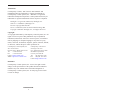
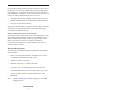
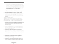
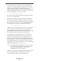
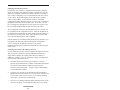
Communication Processor — Embedded Metasys Ethernet Router User Manual #TD990200-0ME Version 1.1 Trademarks Contemporary Controls, ARC Control, ARC DETECT and EXTEND-A-BUS are trademarks or registered trademarks of Contemporary Control Systems, Inc. ARCNET is a registered trademark of Datapoint Corporation. Other product names may be trademarks or registered trademarks of their respective companies. Datalight is a registered trademark of Datalight, Inc. Sockets is a trademark of Datalight, Inc. Portions copyright GPvNO, BK Inet is a trademark of GP van Niekerk Ondernemings BK Copyright 1998-2001 Datalight, Inc., All Rights Reserved Copyright © Copyright 2000-2004 by Contemporary Control Systems, Inc. All rights reserved. No part of this publication may be reproduced, transmitted, transcribed, stored in a retrieval system, or translated into any language or computer language, in any form or by any means, electronic, mechanical, magnetic, optical, chemical, manual, or otherwise, without the prior written permission of: Contemporary Control Systems, Inc. 2431 Curtiss Street Downers Grove, Illinois 60515 USA Tel: +1-630-963-7070 Fax: +1-630-963-0109 E-mail: [email protected] WWW: http://www.ccontrols.com Contemporary Controls Ltd Sovereign Court Two Univ. of Warwick Science Park Sir William Lyons Road Coventry CV4 7EZ UK Tel: +44 (0)24 7641 3786 Fax: +44 (0)24 7641 3923 E-mail: [email protected] Disclaimer Contemporary Control Systems, Inc. reserves the right to make changes in the specifications of the product described within this manual at any time without notice and without obligation of Contemporary Control Systems, Inc. to notify any person of such revision or change. TD990200-0ME i Contents Chapter 1 Introduction ......................................................... 1 Description ................................................................... 1 Features ........................................................................ 2 Specifications ............................................................... 2 Environmental ....................................................... 2 Mechanical ............................................................ 2 Regulatory Compliance ......................................... 3 Port Specifications ....................................................... 3 ARCNET ............................................................... 3 Ethernet ................................................................. 3 COM1, COM2 ....................................................... 4 Ordering Information .................................................. 4 Chapter 2 Operation ............................................................ 5 Description ................................................................... 5 Theory of Operation ..................................................... 6 Setup and Addressing ............................................ 6 Protocols ................................................................ 6 Subnet Communication Upon Network Failure ..................................................... 7 Hardware Requirements .............................................. 7 Design Considerations ................................................. 8 NCM Compatibility ............................................... 8 Quantity of Routers Needed .................................. 8 Physical Considerations ........................................ 8 Design Summary ................................................... 8 Design Restrictions.............................................. 10 Network Management Staff Involvement ........... 11 Metasys May Be Affected. ................................... 11 Ethernet Network May be Affected ..................... 12 Chapter 3 Installation and Commissioning ....................... 13 Hardware Installation ................................................ 13 Configuring the Metasys Ethernet Router ................ 13 Connecting Field Cables ............................................ 15 Reconfiguring the System ................................... 17 Adding a New NCM or PC to an Existing Subnet .............................................. 17 Moving an Existing NCM or PC to a Different Subnet ...................................... 18 TD990200-0ME ii Adding a New Metasys Subnet ........................... 19 Changing the Ethernet Network ......................... 21 Changing the Layout of the Metasys Network ................................................. 21 Chapter 4 Troubleshooting ................................................ 23 Booting Up the Router ............................................... 23 Debugging Ethernet Failures ..................................... 23 XPING Command ............................................... 25 IPSTAT Command .............................................. 26 TESTNET Command .......................................... 26 General Problem Prevention ...................................... 26 Debugging ARCNET Failures .................................. 27 Debugging Router Failures ........................................ 27 Metasys Ethernet Router Does Not Run When Booted ............................... 27 Status Screen Indicates Failure Number 10 ........ 27 Status Screen Indicates Failure Number 9 .......... 27 Status Screen Indicates Invalid Messages ........... 27 Metasys Devices Do Not Respond ....................... 28 All the Devices on One ARCNET Segment Do Not Respond ................................... 28 Multiple ARCNET Segments Do Not Respond .................................................. 28 Metasys Ethernet Router Does Not Respond to Ping Requests ................................... 28 N1 Communications Are Occasionally Unreliable ...................................... 29 Data Cannot Be Viewed on OWS Across Network ................................................... 29 Chapter 5 Service ............................................................... 31 Warranty ..................................................................... 31 Technical Support ...................................................... 32 Warranty Repair ......................................................... 32 Non-Warranty Repair ................................................ 32 Returning Products for Repair ................................... 33 Appendices Appendix A: Metasys Ethernet Router Planning Forms .............................................. 35 Appendix B: Common Metasys Ethernet Router Files ................................................................ 37 TD990200-0ME iii DOS Files .............................................................. Ethernet Files ......................................................... TCP/IP Files ........................................................... Metasys Ethernet Router Files ............................... Metasys Ethernet Router Main Program (ROUTER.EXE) .................................................... Ethernet Communications Tests (TESTNET.EXE) .................................................. Configuration File Download (DOWNLOAD.EXE) ............................................ Router Configuration File (ROUTER.CFG) .................................................... 37 37 37 38 Appendix C: COM Port Communication ..................... Null Modem Cable ................................................ Setting Up HyperTerminal .................................... Using File Transfer Program ................................. 44 44 44 45 38 38 39 39 Appendix D: Jumper and Switch Settings ......................46 Figures 1: Communication Processor installed in MOD HUB ................................................................ 2 2: 10BASE-T Connection .............................................. 3 3: Sample Layout of Metasys Ethernet Router ......................................................... 9 4: Statistics Screen available at COM1..........................24 5: Example of Statistic Screen ..................................... 42 6: Null Modem Cable Detail ....................................... 44 7: Jumper and Switch Settings.......................................46 Tables 1: 10BASE-T Pin Assignments ..................................... 3 2: COM1, COM2 Pin Assignments ............................... 4 3: Common Ethernet Errors ......................................... 25 TD990200-0ME iv TD990200-0ME v 1 Introduction Description The Communication Processor Module provides either router or gateway connectivity between ARCNET and Ethernet networks. Usually in router/gateway applications, a desktop PC compatible computer is dedicated to the task of executing the application program from either a hard disk or floppy disk. On the PC motherboard, two network interface modules are used to connect to the two networks of interest. Using the Communication Processor Module installed into a MOD HUB Modular Active Hub, this same functionality can be provided in a compact and highly reliable configuration. The Communication Processor is a double-wide expansion module that fits into the MOD HUB series of ARCNET Modular Active Hubs. Once installed in a MOD HUB chassis, an ARCNET connection is made through the chassis backplane. On the front panel of the Communication Processor is an RJ-45 connector which provides the 10BASE-T Ethernet connection. Resident in the Communication Processor is an embedded DOS computer with a solid-state flash disk capable of executing a DOS based application program. This user supplied application program could route packets between ARCNET and Ethernet networks that utilize the same network layer or serve as a gateway between different protocols used by the ARCNET and Ethernet networks. For example, a popular transport layer for Ethernet is TCP/IP. In order to route between ARCNET and Ethernet at the network layer (IP), ARCNET would need to be operating a TCP/IP stack as well. For all other situations where different higher level protocols are involved, a gateway program would be needed to effect connectivity between ARCNET and Ethernet. Either situation can be addressed by the Communication Processor. To provide ARCNET to Ethernet connectivity within a Metasys system, the Embedded Metasys Ethernet Router was created by installing the necessary application program onto the Communication Processor. This product replaces the Metasys Ethernet Router program which was originally designed to run on a standard PC workstation. The program that executes the Metasys TD990200-0ME 1 routing has been pre-installed onto the Communication Processor at the factory and immediately begins execution upon power-up. To configure the program, a laptop computer running a terminal emulation program, like HyperTerminal, is attached to one of the COM ports using a null-modem cable. Once configured, the program runs continually. Features • Compact solution for interconnecting ARCNET and Ethernet networks • Embedded router/gateway eliminates the need for a desktop PC • Flash disk replaces unreliable floppy or hard disk • Preloaded application software simplifies installation • Console communication redirected to COM port eliminating need for keyboard or monitor • Preloaded DOS and TCP/IP stack • Automatic booting for stand-alone operation • Can be retrofitted into an existing MOD HUB chassis Specifications Environmental Operating Temperature: 0°C to 60° Storage Temperature: -40°C to +85°C Mechanical Occupies two slots in any MOD HUB series of Modular Active Hubs Figure 1−Communication Processor installed in MOD HUB TD990200-0ME 2 Regulatory Compliance Refer to the MOD HUB series data sheet Port Specifications ARCNET Compliance: Data Rate: Signaling: Port Connector: LED Indicators: Ethernet Compliance: Data Rate: Signaling: Port Connector: Segment Length: LED Indicators: Figure 2−10BASE-T Connection ANSI/ATA 878.1-1999 2.5 Mbps MOD HUB backplane none − requires EXP expansion module ACTIVITY−yellow TX−green ANSI/IEEE 802.3 10 Mbps 10BASE-T Shielded RJ-45 100 m max ACTIVITY−yellow LINK−green Table 1−10BASE-T Pin Assignments TD990200-0ME 3 COM1, COM2 Compliance: EIA-232 (DTE) Data Rate: 19.2 kbaud Port Connector: DB-9 Ordering Information JC-EP-RG Embedded Metasys Ethernet Router Expansion Module Table 2−COM1, COM2 Pin Assignments TD990200-0ME 4 2 Operation Description The Embedded Metasys Ethernet Router integrates Metasys N1 LAN segments with an Ethernet network that uses the TCP/IP (Transmission Control Protocol/Internet Protocol) suite. The router provides the physical connection between a Metasys ARCNET segment and the Ethernet network. It takes advantage of a customer’s existing Ethernet network, while maintaining the dedicated Facility Management System (FMS) communications necessary for complex, time-critical, local control strategies. With the Embedded Metasys Ethernet Router, Metasys controllers communicate transparently over Ethernet, using standard components and maintaining complete compatibility with existing network equipment. From an operator’s view, this coupling of the N1 LAN to Ethernet creates a single large network. No special commands are necessary to switch between networks; data automatically transmits between networks without operator knowledge or intervention. The Embedded Metasys Ethernet Router communicates over an Ethernet network using the TCP/IP protocol. Two networked Metasys Ethernet Routers pass the ARCNET messages between themselves using the User Datagram Protocol (UDP) service provided by TCP/IP. On the Ethernet network, the router is seen as a workstation passing messages to another workstation. If a power failure occurs, the router automatically restarts communications once power is restored. The Embedded Metasys Ethernet Router is derived from the Metasys Ethernet Router program that runs on a standard desktop PC. Instead of a desktop PC, the router program resides in a Contemporary Controls’ Communication Processor Module that fits into two slots of a Contemporary Controls’ MOD HUB ARCNET Modular Active Hub. Power for the Communication Processor comes from the MOD HUB, while ARCNET communication comes from the MOD HUB backplane. An EXP series expansion module is required for making ARCNET connections to other devices. The Ethernet connection is made through a 10BASE-T port on the Communication Processor. Unlike a desktop PC, the TD990200-0ME 5 Communication Processor has no monitor or keyboard. Instead, the monitor/keyboard functionality is accomplished by an external laptop or desktop computer running a terminal emulation program (such as HyperTerminal), while connected to COM ports on the Communication Processor. The Metasys Ethernet Router program is accessed via COM1. The embedded operating system is accessed via COM2. If a terminal emulation program is attached to COM1, real-time routing statistics can be observed. But once the router is started, no such cable connection is required for continued operation. When describing the operation of the Embedded Metasys Ethernet Router, the terms Embedded Metasys Ethernet Router and Metasys Ethernet Router will be used interchangeably. Theory of Operation Setup and Addressing The method of linking the two networks is to separate the N1 LAN into a number of ARCNET subnets. (In this document, the terms “subnet” and “ARCNET segment” are the same.) Each ARCNET subnet then connects to the customer’s Ethernet network via a single Metasys Ethernet Router. The router uses the N1 network addressing scheme to route messages among the various ARCNET segments. Dividing Metasys into multiple subnets has no affect on existing Ethernet communications, and again, remains transparent to the operator. To the operator, the router is simple to use and maintain. Once it is configured to the customer’s network, the router works on its own, uninterrupted. Branch office personnel configure the unit (via HyperTerminal) by accessing a single screen. Once set, the data is saved to a “flash disk.” Upon power up, the program and configuration data is executed without any intervention. There are no moving storage devices on the unit. Protocols The Metasys Ethernet Router uses the UDP/IP communications protocol to transmit messages across the Ethernet network. This is important because it allows the router to easily integrate into existing customer networks that comprise multiple Internet (TCP/IP protocol suite) networks. TD990200-0ME 6 Even though the Metasys Ethernet Router looks like a data router to the Metasys Network, most communications experts would call it a network gateway. To the Ethernet network, the router looks like a normal IBM PC workstation. Unlike typical network gateways and routers, the Metasys Ethernet Router does not process: • routing protocols used by standard network routers, except for UDP/IP communications from other Metasys Ethernet Routers • messages not generated by Metasys The Metasys Ethernet Router responds to TCP/IP “Ping” commands, allowing you to verify that the router is operational and properly connected to the Ethernet network. Subnet Communication Upon Network Failure If the Ethernet network goes down, or the router disconnects or fails, each Metasys subnet continues to function on a standalone basis. A Metasys Ethernet Router failure looks like a general failure of the Metasys N1 network. Devices on a subnet are still able to communicate with other devices on that subnet, but devices on a different subnet are offline. Hardware Requirements The following are additional hardware requirements of the Metasys Ethernet Router: • Metasys Network with NCM200 or NCM300 at any revision; or, NCM101/NCM401at Revision K or later • 10BASE-T Ethernet connection • ARCNET connection (i.e., Metasys N1 LAN) • 120 VAC power at each Metasys Ethernet Router location • Any MOD HUB series powered card cage with two spare slots • At least one EXP expansion module installed in the same MOD HUB Note: Contact Contemporary Controls regarding use of a MOD HUBplus chassis. TD990200-0ME 7 Design Considerations NCM Compatibility The Metasys Ethernet Router is compatible with all versions of the NCM200 and NCM300. If NCM101s/401s are used, they must be Revision K or later. It is possible to upgrade the EPROM chips in older NCM101s/401s for compatibility with the Metasys Ethernet Router. For information about upgrading, contact Field Support Services. (NCM102s cannot be used.) Quantity of Routers Needed The quantity of Metasys Ethernet Routers you need is identical to the number of ARCNET segments connected through the Ethernet system. For example, two Metasys Ethernet Routers are required to connect two ARCNET segments over one Ethernet segment (see Figure 3). A router is placed at each location where the Ethernet segment meets the ARCNET segment. Up to 50 Metasys Ethernet Routers can be used on each Metasys Network (i.e., all ARCNET segments). Physical Considerations The router can be installed in a variety of ways, depending on the job site. When selecting a location, consider the following: 1. 2. The location must have access to the customer’s Ethernet network, the ARCNET segment that the router will service, and power. Depending upon the model, a MOD HUB can be panelmounted, rack-mounted or desktop mounted. See MOD HUB manual for details. Design Summary Use these steps as a guideline when designing a Metasys Ethernet Router Network, referring to Figure 3 for an example: 1. Lay out the network as you would a normal Metasys N1 Network. Determine the number and location of NCMs and Operator Workstations that will service the facility. 2. Determine which portions of the network will use ARCNET and which will use Ethernet. The network layout must consist of multiple ARCNET segments connected by the customer’s Ethernet network. The Ethernet network must be a single Local Area Network (LAN) that can interconnect all of the ARCNET segments. TD990200-0ME 8 Note: If the Ethernet network consists of multiple Ethernet segments, the segments must be connected using LAN Routers that support the TCP/IP protocol suite. Intermediate networks that use other communications technology (FDDI, Token Ring) are acceptable if the intermediate networks are high speed. Low speed networks (e.g., 9600-baud serial lines) will cause unacceptable delays to the Metasys N1 communications. The resulting network layout will be similar to the sample network shown in Figure 3. Each ARCNET segment will have one Metasys Ethernet Router attached to it. The ARCNET node address on each Metasys Ethernet Router has been preassigned 255. 3. Assign a subnet address to each ARCNET segment. We recommend using the subnet address “1” for the primary ARCNET segment, or the segment that has the most devices attached to it. Assign a unique node address to each NCM or Operator Workstation attached to the N1 network. Node addresses must be unique even if the NCMs are attached to different subnets. Record the subnet and node address information on the Metasys Ethernet Router Planning Form A. (See Appendix A: Metasys Ethernet Router Planning Forms.) Figure 3—Sample Layout of Metasys Ethernet Router TD990200-0ME 9 4. Have the customer’s network communications staff assign IP addresses and provide IP routing information for each Metasys Ethernet Router. Record this information on the Metasys Ethernet Router Planning Form B. (See Appendix A: Metasys Ethernet Router Planning Forms.) Append the ARCNET Subnet addresses from form A to form B. 5. Using the Metasys Ethernet Router Planning Form B, configure each router by accessing its configuration screen. (See Chapter 3.) 6. Use the assigned subnet and node addresses to address each of the Metasys NCMs and PCs. When creating the DDL files for the system, use the subnet and node addresses in the NETWORK and GLOBAL DDL files. Note: Since you are converting multiple standalone networks into one large network, verify that no duplicate system names exist. If duplicates exist, you must change them to unique system names in both DDL and GPL. If you are converting an existing system to use Metasys Ethernet Routers, you’ll need to update and recompile the DDL files when the routers are installed. Be sure to recompile all of the DDL files, including all of the NC files. Failure to recompile all of the DDL files could result in application failures for those NCMs located on new ARCNET segments. Design Restrictions 1. The system should not use any realtime control strategies that require data transfers across the Ethernet network. Because the Ethernet network may experience delays and down time caused by non-Metasys equipment, the network is subject to variations in performance. Realtime control strategies can be used between NCMs located on a common ARCNET segment. 2. Use caution when defining critical alarm reports that must cross the Ethernet. Avoid alarms related to life safety because they may not arrive at the Operator Workstation or printer if the customer’s Ethernet network is down. TD990200-0ME 10 3. Use of a customer’s Wide Area Network (WAN) is not recommended. The delays associated with Wide Area Networks may be unacceptable for operation of the Metasys Network. 4. If the system contains a JC/85 Gateway, the Gateway points should not be mapped to objects that reside in NCMs located on different subnets. The JC/85 Gateway obtains the status for all objects that are defined in the Gateway at frequent intervals (every 1-5 seconds). This creates a large amount of message traffic on the N1 network. If this message traffic is routed across the Ethernet, it will (a) add excessive loading to the customer’s Ethernet network, (b) slow down the operation of the JC/85 Gateway, and (c) result in sporadic offline reports for objects located in the remote NCMs. 5. For the same reasons, if the system contains a Network Port, the Network Port cannot map its analog data points to objects that reside in NCMs located on different subnets. 6. As with all Metasys networks, the NCMs and PCs in the network must all use a common time zone, even if the devices physically reside in different time zones. Network Management Staff Involvement When installing the Metasys Ethernet Router, work closely with the network management staff at the job site. They will know the intricacies of the Ethernet network to which you will be connecting. Get them involved as much as possible. They should be able to provide you with the following: • Ethernet connections • assignment of IP addresses • debugging expertise during installation and commissioning the Metasys Ethernet Router Metasys May Be Affected Realize that the Ethernet network will affect the Metasys N1 Network. It can do so in these ways: • Ethernet traffic may slow down the performance of the Metasys N1 Network. TD990200-0ME 11 • Excessive traffic or Ethernet failures may cause Metasys offline reports. An offline report is generated if a Metasys message response is not received within 12 seconds. • Customer equipment attached to the Ethernet network could cause Ethernet network down time. In order to minimize the impact of these problems, consider the following: • Avoid using Ethernet networks running at more than 20% of capacity. • Avoid networks using slower speed links for routing (< 56 kbps). • Do not use control algorithms that cross the Ethernet network. In particular: do not share an object between the two networks; do not initiate closed loop control; and do not program interlocks between NCMs across the Ethernet network. Also, due to the unknown operation of customer devices on the Ethernet network, the Metasys Network may not be as reliable as before. Ethernet Network May Be Affected The Metasys Ethernet Router may affect the Ethernet network. Three points can be made here: • Metasys Ethernet Routers look like standard PCs to the Ethernet network. Metasys Ethernet Routers use the UDP/IP protocol for data transmission. • Typical Metasys loading will be less than 0.1% of the Ethernet bandwidth per Metasys node. During large data transfers, such as during downloads, loading is no higher than 1%. The base traffic level generated by Metasys is calculated as follows: (Number of Metasys Nodes)*(Number of Ethernet Routers-1) = Packets/Minute • Each packet is about 150 bytes long. Sharing data between NCMs or accessing data causes additional traffic. • Maximum data packet size is 512 bytes plus the UDP header. Typically, the packet size is much smaller. TD990200-0ME 12 3 Installation and Commissioning Hardware Installation The Communication Processor must be installed into two spare slots of a MOD HUB series ARCNET modular active hub. Refer to the MOD HUB series User Manual for detailed information on installing the MOD HUB. With the power off on the MOD HUB, remove any filler plates and install the Communication Processor into the hub and hand tighten the knurled screws. At least one additional expansion module (EXP) must reside in the MOD HUB along with the Communication Processor. For example, an EXP-CXS 4-port coaxial star expansion module could be used to connect to the Metasys N1 ARCNET subnet. Once an appropriate expansion module and the Communication Processor are installed, the unit is ready for configuration. Configuring the Metasys Ethernet Router The Communication Processor, on which the Metasys Ethernet Router program resides, is actually a DOS computer with an Ethernet port, ARCNET port, TCP/IP stack, BIOS and a flash disk which emulates a disk drive. The router program has been preloaded at the factory, but it must be configured. To aid in this process, Planning Forms have been provided in Appendix A. Note: Unlike previous versions of the Metasys Embedded Router, the configuration program (CONFIG.EXE) cannot be run from DOS — it can only be called from within the main program during the boot-up procedure. Monitor and keyboard functionality has been redirected to the two DB-9 connectors (COM1 and COM2) located on the front of the Communication Processor. Attach a short null-modem cable from COM1 to a COM port on either a laptop or desktop computer running a terminal emulation program like HyperTerminal. Set the program for 19.2 kbps, 8 bits, no-parity and no hand shaking. (A pinout of a null modem cable and more information on HyperTerminal can be found in Appendix C). Once the terminal emulator is ready, turn on the power to the MOD HUB which houses the Communication Processor. You will notice that the MOD HUB RECON light is on and the TIMING light is off. TD990200-0ME 13 This is normal. The two PWR lights should be on, but the Communication Processor should have no lights on. The Communication Processor will test its memory and then execute its AUTOEXEC.BAT file. This will take less than a minute. You will observe a message that will allow you to halt the booting process in order to access the Ethernet Router Configuration screen. Hit any key during this pause and the screen will be displayed. At the bottom of the screen there are instructions on what keys to press to perform certain editing tasks. The left side of the screen displays information to be loaded into the SOCKET.CFG file. This is the Metasys Ethernet Router IP address, Subnet Mask and Existing LAN Router IP address. On the right side of the screen is data that is written to the ROUTER.CFG file. This information includes switches (e.g., /S) and all ARCNET subnet addresses with corresponding Metasys Ethernet Router IP addresses. This information, except the switch settings, must be identical on all Metasys Ethernet Routers. There is a provision for setting the Extended Timeout value of the ARCNET subnet. The default is 0 and in the majority of applications, it should be left at 0 meaning normal timeouts. Extended timeouts are only required on large fiber optic installations where the ARCNET network diameter exceeds 5 km. TD990200-0ME 14 Using the Metasys Ethernet Router Planning Form B in Appendix A, add to this file the ARCNET Subnet Address (Column 1) and IP Address (Column 2) of each Metasys Ethernet Router that will be connected. Specify these two addresses on the same line and above the “000” terminating flag at the end of the file. The # symbol means that the text following the # is a remark. The following is an example for three Metasys Ethernet Routers: 1 2 3 192.168.20.91 192.168.20.23 192.168.20.56 The SOCKET.CFG file can be edited the same way. Specify correct values for these parameters: Metasys Ethernet Router IP address, Subnet Mask and Existing LAN Router IP address. Obtain this information from the Metasys Ethernet Router Planning Form B. Simply enter them in the blanks allowed. Save the data to the ROUTER.CFG and the SOCKET.CFG files by pressing Ctrl-K. This will save the data and transfer program control to ROUTER.EXE. The TX light on the Communication Processor’s ARCNET port should light and the ACT light should flash as the ARCNET port attempts to find other ARCNET nodes. The TIMING light on the MOD HUB should light indicating that the Communication Processor is sending valid ARCNET signals down the MOD HUB backplane. Note: When entering IP addresses, care should be taken to avoid a trailing space which, although invisible onscreen, will nevertheless cause the address to be incorrect. Connecting Field Cables 1. Connect the ARCNET cable from the Metasys N1 ARCNET subnet to one of the spare ports on an expansion module located in the same MOD HUB as the Communication Processor. If there is network activity on the subnet, then the activity light for that expansion port should light. Depending upon the number of nodes on the subnet, the RECON light may or may not stay on. Disregard the RECON light for the moment. 2. Connect the cable from the Ethernet network to the Communication Processor’s 10BASE-T port. If the cabling is correct and there is either an Ethernet hub, Ethernet LAN router or Ethernet network interface module on the other end of the TD990200-0ME 15 cable, the green Link LED should go on. This light must be on before moving to the next step. 3. Type “Q” to terminate the application and exit to DOS. At this point, the null-modem cable must be moved from COM1 to COM2 to enable DOS functionality. Once the cable has been attached to COM2, the DOS prompt should be visible. You can clear the screen by typing in CLS and then return. 4. Verify that the router is communicating with Metasys by using TESTNET. TESTNET reads the configuration file (ROUTER.CFG) and attempts to “ping” each router that is listed. You will notice that the ACT LED near the 10BASE-T port will flash indicating a proper transmission. To run TESTNET, type the following at the DOS prompt: testnet TESTNET will list the communication status for each router. Example: Status of the Metasys Ethernet Routers: Router 192.168.20.91 is responding Router 192.168.23.23 is responding Router 192.168.20.56 is responding Copy the configuration file to every Metasys Ethernet Router in the network using the DOWNLOAD utility or enter the data manually into each router (for information on using the DOWNLOAD utility see page 39). These IP addresses must be identical for all routers on the job. Once the DOWNLOAD has been accomplished, execute the router program by typing in ROUTER and return. If configured properly, the Metasys Ethernet Router should function correctly and the RECON LED on the MOD HUB should be off. To view router statistics, the null-modem cable must be reattached to the COM1 port. If the resulting display is garbled, refresh the screen by pressing the “R” key. If the router configuration was not set up properly, the router will stop running and continuously display an error message with the instruction to press “Q” to quit to DOS. To determine the problem, refer to Chapter 4: Troubleshooting. TD990200-0ME 16 Reconfiguring the System Over time, a Metasys Network that uses Metasys Ethernet Routers may have to be reconfigured to account for additions and changes to the system. The reconfigurations that a system may undergo can be classified as: • • • • • adding a new NCM or PC moving an NCM or PC adding a new Metasys subnet changing the Ethernet network changing the layout of the N1 network This section describes the steps necessary to perform each of these different types of reconfigurations. Adding a New NCM or PC to an Existing Subnet Adding a new NCM or PC to Metasys does not require any changes to the Metasys Ethernet Router hardware or software. An NCM101/ 401 that is added to a Metasys Ethernet Router system must be Revision K or later. All NCM200s and NCM300s are compatible with the Metasys Ethernet Router. To add a new NCM or PC to an existing subnet: 1. Determine the correct subnet and node address for the new NCM or PC. The subnet address must match the subnet address for the ARCNET segment to which the NCM or PC connects. The node address must be unique. You cannot duplicate any node addresses, even if the two devices reside on different subnets. 2. If the device is an NCM, determine the correct subnet and node address for its archive device. 3. Set the subnet and node address for the device as you normally do. • For a PC, set the node address using the switches on the ARCNET card (note: PS/2 system cards do not have switches, so PS/2 users can ignore this) and specify the subnet and node addresses in the DDL network configuration file. TD990200-0ME 17 • For an NCM, use NCSETUP to set the subnet and node addresses. When using NCSETUP, don’t forget to specify the correct subnet and node address for the archive device. 4. Add the device to the system database, either by updating the DDL global file or by using a device definition window. 5. Physically attach the new NCM or PC to the ARCNET segment that you have selected. 6. You do not need to make any changes to the Metasys Ethernet Router or the ROUTER.CFG file. The router automatically routes messages correctly using the subnet address for the new device. Moving an Existing NCM or PC to a Different Subnet You may want to change the ARCNET segment to which an NCM or PC is attached. This may be required because an NCM or PC is moved to a new location or because the ARCNET cable layout has been changed. Moving an NCM or PC to a different subnet does not require any changes to the Metasys Ethernet Router software. To move a device to a different subnet, follow these steps: 1. Determine the new subnet and node address for the NCM or PC. You will probably use the same node address for the device, but if you decide to change the node address, it must be unique. You cannot duplicate any node addresses, even if the two devices reside on different subnets. The device’s subnet address will have to change to match the subnet address for the ARCNET segment to which the device will be moved. 2. If the device is an NCM, you may want to change its archive device. If you decide to change the archive device for the NCM, determine the subnet and node address for the new archive device. 3. Change the subnet and node address for the device as you normally do. • For a PC, set the node address using the switches on the ARCNET card (note: PS/2 system cards do not have switches, so PS/2 users can ignore this) and specify the subnet and node addresses in the DDL network configuration file. TD990200-0ME 18 • For an NCM, use NCSETUP to set the subnet and node addresses. Once the subnet address for an NCM is changed, you will not be able to communicate with the NCM over the N1 network until it is physically attached to its new subnet. When using NCSETUP, don’t forget to specify the correct subnet and node address for the archive device. 4. Change the subnet and node addresses for the device in the Metasys database. This is done by updating the DDL global file. 5. Physically attach the device to its new ARCNET segment. 6. You do not need to make any changes to the Metasys Ethernet Router or the ROUTER.CFG file. The router automatically routes messages correctly based on the new subnet address for the device. Adding a New Metasys Subnet When a new device cannot be attached to one of the existing ARCNET segments, a new subnet and a new Metasys Ethernet Router must be added. To add a new subnet, do the following: 1. Determine a location for the new Metasys Ethernet Router. The router must have access to electrical power, a connection to the customer’s Ethernet network, and a connection to the new ARCNET segment. 2. Select a new subnet address for the new ARCNET segment. The subnet address must be unique (not previously used for a different ARCNET segment). 3. Obtain Internet address information for the new Metasys Ethernet Router from the customer’s communications/computer support staff. The information should include an IP address for the Metasys Ethernet Router, the subnet mask that is used, and an IP address for the customer’s existing LAN Router (if the customer’s Ethernet network uses LAN Routers). 4. Obtain another Communication Processor with Metasys Ethernet Router program installed into two spare slots of a MOD HUB powered card cage. 5. Install the new Metasys Ethernet Router and attach the new router to the Ethernet network and to the ARCNET network. TD990200-0ME 19 Verify that the Metasys Ethernet Router is communicating by “pinging” it from another Ethernet equipped device. This can be done from another Metasys Ethernet Router that has a terminal emulator attached or from any Ethernet device that has TCP/IP communications software. For example, to ping a new router with IP address 192.168.22.236, enter: xping 192.168.22.236 The response to the XPING command should indicate that the new router is communicating. 6. Modify the ROUTER.CFG file that is located in each Metasys Ethernet Router using the configuration program. Add a new line to the file that lists the subnet address and the IP address for the new router. For example, if you are adding subnet number 12 with IP address 192.168.22.236, add the following line: 12 192.168.22.236 Add the new line to the ROUTER.CFG file before the line that contains the three zeros (000). After you have edited the file, save it using the save command (Ctrl-K). Then use the DOWNLOAD program to copy the new ROUTER.CFG file onto all of the Metasys Ethernet Routers used in the system. To download the new ROUTER.CFG file, reboot the router containing the new ROUTER.CFG file, press “Q” after the router has started running, and enter “DOWNLOAD” at the DOS prompt. Follow the instructions provided and note any messages displayed. After the new ROUTER.CFG file has been successfully downloaded to all of the other routers, reboot the originating router by typing in REBOOT. For more information on the ROUTER.CFG file, refer to page 39. Note: 7. The DOWNLOAD program must be run from a router that was previously configured. Existing routers will not accept a download from a router that is not configured in the “old” CONFIG file. Add the new NCM or PC to the new ARCNET segment. To do this, follow the procedures for adding an NCM or PC to an existing ARCNET segment, as described previously. TD990200-0ME 20 Changing the Ethernet Network Occasionally, the customer’s communications/computer staff may decide to rearrange their Ethernet network. Normally this will not impact the operation of the Metasys Ethernet Router, except that it may result in a temporary loss of communications with one or more of the routers. Should this happen, all NCMs and PCs on those subnets will go offline. If the customer decides to change the configuration of their Ethernet network, you may have to change the IP address information stored in each router. To do this, you will have to change the configuration for each router, and you may also have to change the ROUTER.CFG file stored in each router. The configuration is stored in the SOCKET.CFG file. The file can be modified from the configuration screen. Enter the IP address for the Metasys Ethernet Router, the subnet mask and the IP address for the customer’s existing LAN router. Once the data is entered and saved, the SOCKET.CFG file will be updated. If the IP address for the Metasys Ethernet Router was modified, you must update the ROUTER.CFG file through the configuration screen. Change the IP address as needed. Then use the DOWNLOAD program to update the ROUTER.CFG file on all the other routers. Changing the Layout of the Metasys Network In some situations you may want to reorganize the Metasys Network. This may involve joining two existing ARCNET subnets into a single subnet, splitting an existing subnet into two subnets, or adding new subnets. If you are performing a major reconfiguration of the network, follow these steps: 1. Determine the new network layout for Metasys. The new network layout should show a number of ARCNET subnets that are connected using Metasys Ethernet Routers and the customer’s Ethernet network. Assign a unique subnet number to each ARCNET segment. 2. Using the new network layout, determine where the Metasys Ethernet Routers will be located. For each router, determine if it is an existing router or a new router. If you will be installing new routers, you will have to obtain them. 3. Fill out a set of Metasys Ethernet Router planning forms for the new network layout. You should have filled out a set of forms TD990200-0ME 21 when the routers were first installed. The Metasys Ethernet Router Planning Form B will be used to configure each of the Metasys Ethernet Routers. If you will be installing new routers, follow the procedures beginning on page 13. 4. Use the Metasys Ethernet Router Planning Form B to generate a new ROUTER.CFG file. The file should be a list of subnet address and IP address pairs of the form: nnn xxx.xxx.xxx.xxx where “nnn” is the subnet address and “xxx.xxx.xxx.xxx” is the IP address for the Metasys Ethernet Router attached to that subnet. The last line of the ROUTER.CFG file should be a line containing “000.” Once you have built a new ROUTER.CFG file that lists all of the subnets, a copy must be placed in each Metasys Ethernet Router attached to the system. 5. Configure the new hardware and install it as described in a previous section, Adding a New Metasys Subnet. 6. Use the Metasys Ethernet Router Planning Form B to update the TCP/IP configuration on each of the existing Metasys Ethernet Routers. The procedure for updating the TCP/IP information is described in a previous section, Changing the Ethernet Network. 7. To update the DDL files for Metasys, use the Metasys Ethernet Router Planning Form A. The only changes you should have to make are to the Network Definition and the Global Definition DDL files to change the subnet addresses for each of the NCMs and PCs. If you add new NCMs to the system, you will most likely update the DDL files to add the data base information for the new NCMs when you update the subnet and node addresses for the Metasys devices. TD990200-0ME 22 4 Troubleshooting Because the Metasys Ethernet Router hardware consists of an embedded DOS computer, knowledge of DOS will help in troubleshooting the system. Booting Up the Router When first activated, the Metasys Ethernet Router computer runs through a self test. If an error is detected, the router will stop operating then repeatedly display an error message advising the operator to press “Q” to end the router program and exit to DOS. Note: After pressing “Q” to exit the router program, the nullmodem cable must be moved from COM1 to COM2, so that DOS commands can be entered. Under DOS control type ROUTER − to restart the router, or REBOOT − to reboot the system. Debugging Ethernet Failures Software tools are provided with the product for checking Ethernet network errors. These include the programs XPING.EXE, IPSTAT.EXE, TESTNET.EXE, and a router statistics mode. The nature of the XPING and IPSTAT programs should be familiar to someone with previous experience with TCP/IP software. Prior to using the router statistics mode tools, you may need to modify the router configuration file (ROUTER.CFG). Add the following three switches (upper case letters only) if they are not already present: /A /S /M When the router is running, it displays statistical information as shown in the example of Figure 4 — providing the null-modem cable is attached to COM1. This display shows ARCNET and Ethernet message counters. TD990200-0ME 23 The statistics screen normally shows the ARCNET and network message Idle counters rapidly incrementing. The counters for Invalid, Retry, and Failure messages should be zero. The ARCNET and network Normal counters and the ARCNET and Ethernet Broadcast counters increment as messages are received. NETWORK MESSAGES: ARCNET MESSAGES: Idle: Normal: Broadcast: 4580890 Idle: 33589 4580885 Normal: 2202 Broadcast: 33589 2202 Retry: 0 Retry: 0 Invalid: 0 Invalid: 0 Failure: 0 Error: Last Invalid Message: STATSCRN Figure 4− Statistics Screen available at COM1 • If an Invalid message counter is non-zero, it indicates that an Invalid Metasys message was detected. The last Metasys message that was invalid is displayed. • A non-zero Failure counter indicates an Ethernet problem, and results in the display of an error number. Common Ethernet error numbers are: TD990200-0ME 24 Error Number Meaning 1 In Use 2 DOS Error 3 Memory Error 4 Network Connection Error 6 Bad Packet 7 No Host 8 Cannot Open Connection 9 Ethernet Network Unreachable (typically a customer LAN Router failure) 10 Host Unreachable (a remote Metasys Ethernet device such as a NCM, OWS or Metasys Ethernet Router is off-line) 12 Time Out 15 No Servers 16 Server Error Table 3−Common Ethernet Errors If a defined router is offline when another router boots up, error 10 displays on the statistics screen. This error just means that a router at one of the defined IP addresses did not respond as expected. The router software flags this router as offline and will not send any messages to it until it comes back online. The other three Ethernet debugging tools are executed from the DOS prompt once the router program has been stopped. After stopping the router by hitting the “Q” on the keyboard, switch the nullmodem cable to COM2 to exercise DOS control. Note: Once “Q” is hit, the router software stops transmitting Metasys messages, and its subnet loses communications with the rest of the Metasys Network. To restart the router from the DOS prompt, type REBOOT. XPING Command The XPING command verifies that messages can be sent and received over the Ethernet network by transmitting continuous pings. The command format is: xping xxx.xxx.xxx.xxx interval TD990200-0ME 25 Where “xxx.xxx.xxx.xxx” is the IP address of a computer on the Ethernet network. Other Metasys Ethernet Routers and TCP/IPcompatible computer systems send back a response. The “interval” value is the number of clock cycles between pings and can range from 1 to 32767. The default interval is 10 cycles. The pinging will continue until stopped by any keystroke. Failures are caused by cable problems, device driver configuration problems, or computers being offline. The display indicates if the ping was successful and the approximate response time. A normal response time for Ethernet is 25 to 50 milliseconds. If there are any Ethernet communications errors, they are noted. If the Ethernet network is running properly, no errors are reported. Ipstat Command The program IPSTAT.EXE reports various useful statistics. To launch IPSTAT, type the following at the DOS prompt: IPSTAT The resultant display reports the routing table, packet count, detected errors and memory usage. If the Ethernet is operating properly, the IPSTAT statistics should not report any errors. Testnet Command The Testnet command reads the configuration file (ROUTER.CFG) and attempts to ping each router that is listed. The command format is: testnet Testnet lists the communication status for each router. If Testnet can talk to some routers but not others, the configuration files may contain inaccurate information, such as a wrong address. To correct bad addresses, reboot the system and access the configuration screen during the boot process. General Problem Prevention 1. Configure the Metasys Ethernet Router’s IP address, existing LAN Router IP address, and subnet mask using information from the customer’s network manager. 2. The Metasys ARCNET subnet addresses need to match the router configuration file. Each ARCNET segment needs a TD990200-0ME 26 unique subnet address. The Metasys DDL files must use the correct subnet addresses. 3. All of the Metasys devices on one ARCNET segment need to have the same subnet address. Although ARCNET hubs and links result in multiple ARCNET segments, for the purposes of the Metasys Ethernet Router, it is all considered one subnet. 4. Time-critical control strategies should not cross Ethernet segments. Debugging ARCNET Failures Use standard Metasys debugging tools to diagnose and correct suspected ARCNET failures. The Metasys Ethernet Router displays message statistics. The router should increment the ARCNET message counter (broadcast) when it is connected to any ARCNET NCM or workstation. This counter will increment even if multiple subnets are not defined. If this counter does not increment, there may be a problem with the router itself. Debugging Router Failures Several of the difficulties discussed in this section may be caused by a global DDL file that is inaccurate or has not been downloaded. Therefore, before going on, verify that the current global file is up-to-date and fully downloaded. Metasys Ethernet Router Does Not Run When Booted The ROUTER.CFG file should be examined for errors. Status Screen Indicates Failure Number 10 One or more Metasys Ethernet Routers were offline when this router started. Normal communication resumes when the other routers come online. Status Screen Indicates Failure Number 9 This is caused by the customer’s existing LAN Router being offline. Verify that the existing LAN Router IP address is correct. Check with the customer’s LAN manager to determine the condition of the existing LAN Router. Status Screen Indicates Invalid Messages 1. An operator tried to access an NCM defined in the DDL, but the NCM is on a subnet that has not been defined in the TD990200-0ME 27 ROUTER.CFG file. Update the ROUTER.CFG file to include the undefined subnet. 2. The Metasys Network generated a message that contained an invalid address. Write down the message information that appears on the screen and call Field Support Services. Metasys Devices Do Not Respond If any other node on the same ARCNET segment responds normally, the router is not at fault. The problem could be caused by a Metasys device failure or an ARCNET cable problem. Check the device for any malfunctions, and use troubleshooting information from the N1 Local Area Network Technical Bulletin (in FAN 636). All the Devices on One ARCNET Segment Do Not Respond 1. If other ARCNET segments are working, the problem is isolated to the failing segment. Use Xping to find out if the suspect router responds to Ethernet messages. 2. If the router responds, look at the ARCNET cable and Metasys equipment. 3. If the router does not respond, look at the router and the Ethernet network. (See Metasys Ethernet Router Does Not Respond to Ping Requests, further on.) Multiple ARCNET Segments Do Not Respond This could be caused by a router configuration problem or an Ethernet problem. Use TESTNET to determine which routers respond. Verify that the configuration file (ROUTER.CFG) is correct. Check the Metasys DDL files for correct subnet/node addresses. Check the configuration at each failing router. Check the Ethernet LAN for failures. Metasys Ethernet Router Does Not Respond to Ping Requests This could be caused by problems with the router or problems on the Ethernet LAN. Check the router configuration. Check that the Metasys Ethernet Router IP address, existing LAN Router IP address and the subnet mask are correct for this router. Verify that the file ROUTER.CFG is correct for this network. Use IPSTAT to look for errors connecting to the Ethernet. If the router is running and appears to be configured properly, the problem is probably due to an Ethernet failure. Check with the network administrator to verify that the network has not been changed and is functional. TD990200-0ME 28 N1 Communications Are Occasionally Unreliable 1. Ethernet communications may be unreliable. Use IPSTAT or XPING to check for Ethernet errors. If transmit or receive errors are indicated, check with the network administrator for the Ethernet network to determine if they have been experiencing Ethernet downtime or excessively heavy network traffic. 2. ARCNET communications may be unreliable. Check the ARCNET cables for any subnets that are experiencing problems. 3. Metasys N1 communications may be timing out. If you have eliminated the other possible causes of this problem, contact Field Support Services for assistance. Data Cannot Be Viewed on OWS Across Network The Metasys Operator Workstation (OWS) can be improperly configured so that it transmits broadcast ARCNET messages, but not pointto-point ARCNET messages. The symptoms are as follows: • • • • • No nodes come online at the OWS. The OWS cannot open any focus windows that require data from a remote node. The OWS is online to the rest of the system, but cannot access any data over the network. The Metasys Ethernet Router statistic screen shows broadcast traffic from the OWS but not any normal message traffic. Other nodes may transmit Retry messages to the OWS. These problems are caused by an IRQ conflict at the OWS. The normal IRQ setting for the ARCNET card is 7. Some system BIOSes will conflict with this setting. To resolve the conflict, change the ARCNET IRQ to a different IRQ setting that is not currently being used. TD990200-0ME 29 TD990200-0ME 30 5 Service Warranty Contemporary Controls (CC) warrants its product to the original purchaser for one year from the product’s shipping date. If a CC product fails to operate in compliance with its specification during this period, CC will, at its option, repair or replace the product at no charge. The customer is, however, responsible for shipping the product; CC assumes no responsibility for the product until it is received. This warranty does not cover repair of products that have been damaged by abuse, accident, disaster, misuse, or incorrect installation. CC’s limited warranty covers products only as delivered. User modification may void the warranty if the product is damaged during installation of the modifications, in which case this warranty does not cover repair or replacement. This warranty in no way warrants suitability of the product for any specific application. IN NO EVENT WILL CC BE LIABLE FOR ANY DAMAGES INCLUDING LOST PROFITS, LOST SAVINGS, OR OTHER INCIDENTAL OR CONSEQUENTIAL DAMAGES ARISING OUT OF THE USE OR INABILITY TO USE THE PRODUCT EVEN IF CC HAS BEEN ADVISED OF THE POSSIBILITY OF SUCH DAMAGES, OR FOR ANY CLAIM BY ANY PARTY OTHER THAN THE PURCHASER. THE ABOVE WARRANTY IS IN LIEU OF ANY AND ALL OTHER WARRANTIES, EXPRESSED OR IMPLIED OR STATUTORY, INCLUDING THE WARRANTIES OF MERCHANTABILITY, FITNESS FOR PARTICULAR PURPOSE OR USE, TITLE AND NONINFRINGEMENT. Repair or replacement as provided above shall be the purchaser’s sole and exclusive remedy and CC’s exclusive liability for any breach of warranty. TD990200-0ME 31 Technical Support Contemporary Controls (U.S.A.) will provide technical support on its products by calling +1-630-963-7070 each weekday (except holidays) between 8:00 a.m. and 5:00 p.m. Central time. Contemporary Controls Ltd (U.K.) will provide technical support on its products by calling +44 (0)24 7641 3786 each weekday (except holidays) between 8:00 a.m. and 5:00 p.m. United Kingdom time. If you have a problem outside these hours, leave a voice-mail message in the CC after hours mailbox after calling our main phone number. You can also fax your request by calling +1-630-963-0109 (U.S.) or +44 (0)24 7641 3923 (U.K.), or contact us via e-mail at [email protected] or [email protected]. You can visit our web site at www.ccontrols.com. When contacting us, please leave a detailed description of the problem. We will contact you by phone the next business day or in the manner your instructions indicate. We will attempt to resolve the problem over the phone. If unresolvable, the customer will be given an RMA number in order that the product may be returned to CC for repair. Warranty Repair Products under warranty that were not subjected to misuse or abuse will be repaired at no charge to the customer. The customer, however, pays for shipping the product back to CC while CC pays for the return shipment to the customer. CC normally ships ground. International shipments may take longer. If the product has been determined to be misused or abused, CC will provide the customer with a quotation for repair. No work will be done without customer approval. Non-Warranty Repair CC provides a repair service for all its products. Repair charges are based upon a fixed fee basis depending upon the complexity of the product. Therefore, Customer Service can provide a quotation on the repair cost at the time a Returned Material Authorization (RMA) is requested. Customers pay the cost of shipping the defective product to CC and will be invoiced for the return shipment to their facility. No repair will be performed without customer approval. If a product is determined to be unrepairable, the customer will be asked if the product can be replaced with a refurbished product (assuming one is available). Under no circumstances will CC replace a defective product without customer approval. Allow ten working days for repairs. TD990200-0ME 32 Returning Products for Repair To schedule service for a product, please call CC Customer Service support directly at +1-630-963-7070 (U.S.) or +44 (0)24 7641 3786 (U.K.). Have the product model and serial number available, along with a description of the problem. A Customer Service representative will record the appropriate information and issue, via fax, an RMA number—a code number by which we track the product while it is being processed. Once you have received the RMA number, follow the instructions of the Customer Service support representative and return the product to us, freight prepaid, with the RMA number clearly marked on the exterior of the package. If possible, reuse the original shipping containers and packaging. In any event, be sure you follow good ESD-control practices when handling the product, and ensure that antistatic bags and packing materials with adequate padding and shock-absorbing properties are used. CC is not responsible for any damage incurred from improper packaging. Shipments should be insured for your protection. Ship the product, freight prepaid, to the location from which it was purchased: Contemporary Control Systems, Inc. 2431 Curtiss Street Downers Grove, IL 60515 U.S.A. Contemporary Controls Ltd Sovereign Court Two University of Warwick Science Park Sir William Lyons Rd. Coventry CV4 7EZ U.K. TD990200-0ME 33 TD990200-0ME 34 Appendices Appendix A: Metasys Ethernet Router Planning Forms Metasys Ethernet Router Planning Form A ARCNET Node Address ARCNET Subnet Address NCM/ OWS TD990200-0ME 35 Description (Optional) TD990200-0ME 36 Appendix B: Common Metasys Ethernet Router Files A partial listing of Embedded Metasys Ethernet Router files, organized by function, appears below and on the following page. Those files which are not self-explanatory are discussed on the following pages. DOS Files AUTOEXEC.BAT MS-DOS auto-execute batch file for the Metasys Ethernet Router CONFIG.SYS MS-DOS configuration file for the Metasys Ethernet Router Ethernet Files NE2000.COM TCP/IP packet driver for NE2000 compatible Ethernet cards. Other Ethernet cards will have their own packet driver program. TCP/IP Files SOCKETP.EXE TCP/IP main program IPSTAT.EXE Program that displays TCP/IP statistics SOCKET.CFG TCP/IP configuration file. XPING.EXE Tests TCP/IP connections to other computers TD990200-0ME 37 Metasys Ethernet Router Files DELAY.EXE Allows OSSTART time to initialize before Router communicates to the COM port. Required for faster PC platforms. DOWNLOAD.EXE Downloads the ROUTER.CFG file to other Metasys Ethernet Routers attached to the Ethernet network. CONFIG.EXE Setup screen configuration program for ROUTER.CFG and PCTCP.INI. OSSTART.EXE Metasys Ethernet Router startup program ROUTER.CFG Metasys Ethernet Router configuration file ROUTER.EXE Metasys Ethernet Router main program RTOSCTSK.EXE Metasys Ethernet Router startup program TESTNET.EXE Tests Ethernet communications with other routers. Metasys Ethernet Router Main Program (ROUTER.EXE) The Metasys Ethernet Router is set up to automatically load and run all of the TCP/IP and router software when the computer is booted. The Metasys Ethernet Router software first loads some Metasys kernel software by running OSSTART.EXE, which loads and runs RTOSCTSK.EXE. The router program, ROUTER.EXE, is then run. If a terminal emulator is attached to the router, a startup screen displays when the computer is booted. Once the router software is running, an operator can type “Q” on the keyboard to terminate the ROUTER.EXE program. To restart the router software, either recycle power or reboot from DOS by typing REBOOT. Ethernet Communications Tests (TESTNET.EXE) The Testnet program looks at the list of Metasys Ethernet Routers defined in the ROUTER.CFG files and attempts to communicate with each of them by issuing TCP/IP Ping commands. The program produces a summary of the communications with each Metasys Ethernet Router as shown below. TD990200-0ME 38 Status of the Metasys Ethernet Routers: Router 192.168.130.8 is responding Router 192.168.110.237 is responding Router 192.168.205.125 is not responding Router 192.168.205.234 is responding Router 192.168.205.235 is not responding Router 192.168.205.236 is responding If a router is not responding, either the Ethernet or the router has failed. Test the Ethernet link, then check connections to the router. Finally, inspect each configuration item in the configuration files. Configuration File Download (DOWNLOAD.EXE) The program downloads the router configuration file (ROUTER.CFG) from one router to all of the other Metasys Ethernet Routers. When the DOWNLOAD program is run, it will prompt for additional information. It will also indicate which routers were downloaded successfully. If a download fails, either rerun the DOWNLOAD program or update the ROUTER.CFG file at the failed routers by hand. The DOWNLOAD program must be run from a router that was previously configured. Existing routers will not accept a download from any device whose address is not in the configuration file. Router Configuration File (ROUTER.CFG) The ROUTER.CFG file is used to configure the Metasys Ethernet Router. It lists the ARCNET subnets that are defined for the system, and it specifies the IP address for the router attached to each subnet. A sample ROUTER.CFG file is shown below: /A /S /M 1 2 33 34 35 36 192.168.130.8 192.168.110.237 192.168.205.125 192.168.205.234 192.168.205.235 192.168.205.236 # # # # # # Subnet Subnet Subnet Subnet Subnet Subnet 000 TD990200-0ME 39 1 - Physical Plant 2 - Admin Building 33 - East Campus 34 - North Campus 35 - West Campus 36 - South Campus The first three lines in the sample file show the specification of router configuration options called switches. There are seven switch options that can be specified. All seven options are specified by an entry in the ROUTER.CFG file consisting of a slash (/) followed by the option letter. The option letters must be capitalized. /A or /B The /A switch and the /B switch control the way that ARCNET broadcast messages are handled by the Metasys Ethernet Router. If neither of these switches are defined, the Ethernet Router sends one IP message to each IP address defined in the ROUTER.CFG file, for every ARCNET broadcast message received. This mode will generate a lot of Ethernet traffic and can cause Metasys nodes to have off-line problems if many of the IP address defined in this file are not present on the network. Including one of these two switches causes the Ethernet Router to send one broadcast message to all of the nodes that are within the broadcast domain of the Ethernet Router. Additional messages are sent to each of the remaining devices that do not receive the broadcast message. The two switches control how the broadcast message is sent on the Ethernet network. The /A switch sends broadcast messages to the all ones IP address (255.255.255.255). The /B switch sends broadcast messages to the network directed address. The /B switch should be used on networks that do not pass the all ones broadcast messages to all parts of a single IP network. Ask your network administrator which type of broadcast message their network supports. (All ones, /A switch , or network directed, /B switch ). The /A switch is set as the default condition. Do not set both switches active at the same time. NOTE: The /B switch can only be used when the Metasys software is at or above release 10.0. /D This switch is used for diagnostic purposes. Using this option displays the contents of all the messages received by the Metasys Ethernet Router. /M Monitor statistics. This outputs statistics to the statistics screen, providing /S has been set to display a template by which the statistics may be meaningfully viewed. TD990200-0ME 40 /S Statistics screen. This displays the router statistics screen via the COM1 port. If the /M switch is set to monitor statistics, the statistics are reported onscreen. If the /M switch is not set, the statistics screen is still displayed, but no statistics are reported. Once per day the statistics counters are zeroed. When statistics are updated to the monitor, router operation does slow down. For optimum performance, turn the statistics display off. If /S is not on, the Johnson Controls copyright page is continuously displayed at COM1, but router operation can still be confirmed by the activity of its LEDs. /T Test option. Causes the router program to evaluate the contents of the ROUTER.CFG file and report any errors. The router halts after the file is processed— therefore, this option should not be specified in an operating router. /U This switch is used to allow Multi-Metasys N1 networks to exist on the same Ethernet network. When configuring the Metasys Ethernet Router to run in a Multinetwork configuration, The ROUTER.CFG file must contain the “/U nnnnn” switch. Replace the nnnnn characters with the UDP port address that was used to configure the other Metasys Ethernet devices that will exist within the target Metasys network. DO NOT use this switch unless you are configuring a Multiple Metasys N1 Network configuration. See the following Metasys manual for more information: LIT-6360175 N1 Ethernet/IP Network Technical Bulletin The lines that follow the configuration options in the ROUTER.CFG file list the Metasys subnets. The first number on each line specifies the Metasys subnet number. The second number specifies the IP address for the router that is attached to that subnet. The descriptions that follow the “#” characters are comments that are ignored. The last line in the file must contain “000.” This indicates the end of the configuration information in the ROUTER.CFG file. The ROUTER.CFG file must be the same (except for the switch settings) for all of the Metasys Ethernet Routers in the system. If the ROUTER.CFG file is updated, it must be copied onto each router. TD990200-0ME 41 This can be done using the DOWNLOAD program or by copying the updated ROUTER.CFG file onto each router by hand. A sample statistics output is shown below: NETWORK MESSAGES: ARCNET MESSAGES: 4580890 Idle: Idle: 33589 Normal: Broadcast: Normal: 2202 Broadcast: 4580885 33589 2202 Retry: 0 Retry: 0 Invalid: 0 Invalid: 0 Failure: 0 Error: Last Invalid Message: STATSC RN Figure 5−Example of Statistics Screen The first column shows the number of ARCNET messages received by the router. The second column shows the number of Ethernet messages received by the router. The Idle counters are incremented whenever the router doesn’t have any messages to process and is idle. When the statistics display on the monitor, the Idle counter increments continuously. Note: Use the Idle counter only as an indication that the router is running. It does not provide an accurate estimate of percent idle time for the router. The Normal message counters indicate the number of Normal (non-broadcast) messages that are received by the router. The Broadcast message counters indicate the number of Broadcast messages received by the router that are destined for all of the nodes in Metasys. The Retry message counter tracks the number of times an RTOS (Real Time Operating System) message is retransmitted; low numbers reflect stable N1 communications. TD990200-0ME 42 The Invalid counters indicate the number of Invalid messages received. An Invalid message is a message that contains an invalid address. The Invalid counters should always be zero during normal operation. If the Invalid message counter is ever non-zero, the latest Invalid message will display on the monitor screen, below the statistics information. The ARCNET Failure counter indicates the number of times an ARCNET message could not be delivered to its destination due to Ethernet errors. While this counter should normally be zero, it will increment if one of the other Metasys Ethernet Routers is offline. TD990200-0ME 43 Appendix C: COM Port Communication Null Modem Cable Since the COM1 and COM2 ports on the Metasys Ethernet Router are wired as a DTE and the COM port on a laptop or desktop computer is wired the same way, a null-modem cable is required between devices Figure 6−Null-Modem Cable Detail Setting Up HyperTerminal HyperTerminal is a terminal emulation program included with Windows 95, 98 and NT. If it is not installed on your machine, go to your Control Panel. Double click the Add/Remove Programs icon. Select the Windows Setup tab. Select the Communications component. Press the details button. Check the HyperTerminal box. Then press the OK button. Then press the next OK button. Windows should then install HyperTerminal. To properly communicate with the Embedded Metasys Ethernet Router you will need to properly configure HyperTerminal. First run HyperTerminal and then: • • • Choose the File menu item. Choose the Properties menu item. In the “Connect using” box select the COM port you are using to communicate with the Metasys Ethernet Router. TD990200-0ME 44 • • • • • • • • • • • • Press the Configure button. Select the Port settings tab. Set the Bits per second to 19200. Set the Data bits to 8. Set the Parity to None. Set the Stop bits to 1. Set the Flow control to None. Press the OK button. Select the Settings tab. Choose the “Terminal Keys” option. In the Emulation box select ANSI. Press the OK button. If you connect to a running Embedded Metasys Ethernet Router you may need to refresh the screen. While the router program is executing press “R” to redraw the screen. Using File Transfer Program Since the Embedded Metasys Ethernet Router has no floppy disk, a file transfer program is required to load new files or change existing files. The program XFER.EXE is a command line DOS file transfer program that supports the Xmodem protocol. The program resides on the router and can communicate with HyperTerminal. Two arguments must be passed when executing the program from the host computer (running HyperTerminal) to indicate direction of transfer and the filename. For example, to transfer a file to the router from the host type in at the DOS prompt the following: xfer in filename.ext Once you hit return the program awaits the transfer. From the menu bar, select Transfer and then Send File. In the dialog box enter the file name and its path. Be sure to select Xmodem protocol. Select Send and the file will transfer. Upon completion, you will need to reboot the router. To reverse the process, type in at the DOS prompt the following: xfer out filename.ext This time select Receive File from the Transfer menu. A dialog box will appear. You will need to specify a folder for receiving the file. Again verify that Xmodem protocol is selected. Select Receive and the transfer will be made. Rebooting will again be required. TD990200-0ME 45 Appendix D: Jumper and Switch Settings The jumper and switch settings available to the user are illustrated in Figure 7 and described below. Figure 7 — Jumper Settings Settings E1 — Memory and Input/Output Jumper Settings The default settings shown in Figure 7 should not be changed. E2 — ARCNET Interrupt Jumper Selection The default IRQ 7 is the normal Metasys interrupt used. E3 — MOD HUBplus Jumper Option The default selection is set to P1. However, if the router is used in a MOD HUBplus, move the jumper to RXC. Communication Jumper Settings * E4 — Serial "Straight" option should not be changed. The defaults for the "Console" S1 — ARCNET Node ID Switch Settings The default settings shown in Figure 7 should not be changed. * NOTE: The original default of E4 was "Console" — as shown by clicking this button : Revised units have a default E4 of "Straight" — as shown by clicking this button : E4 Set to "Console" E4 Set to "Straight" Revised units (default = "Straight") are those with serial numbers F0156602, F0156603, F0156610, F0156611, F0156612, F0156614, F0156621 — and ALL numbers higher than F0156622. TD990200-0ME 46