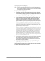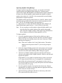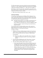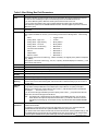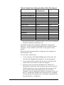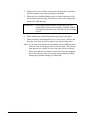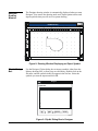
1
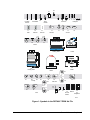
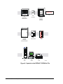
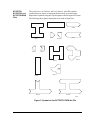
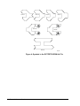
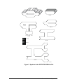
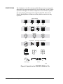
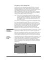
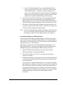
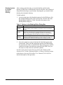
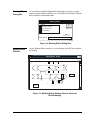
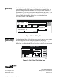
Metasys Network Technical Manual Feature Software Section Technical Bulletin Issue Date 636 1199 Graphics Introduction Page 3 • Theory of Operation • Drawings Provided with Metasys • Fire Graphics Caching 13 • Slide Show 14 *3 5 Setup Procedures 15 • Design Considerations *15 • Setup Considerations 18 • Definition Procedures 19 Windows 33 • Designer Drawing Window 34 • ClipArt Dialog Box 34 • Binding Editor Dialog Box 35 • Binding Editor Window 35 • Bind Dialog Box 36 • Binding Editor Colors Dialog Box 36 *Indicates those sections where changes have occurred since the last printing. © 1999 Johnson Controls, Inc. Code No. LIT-636108 1 www.johnsoncontrols.com 2 Feature Software—Graphics Introduction Theory of Operation Both the Metasys Operator Workstation (OWS) and the Fire OWS used with fire alarm control systems allow you to represent your entire facility in both textual and graphical formats. For example, a System summary displays an air handling unit as a textual list of objects. A system drawing displays the same system with graphical symbols representing the objects. The drawing changes colors to indicate when a change-of-state occurs. You can monitor the following FMS items in a graphical format: • Networks • Objects • Network Devices • CS Object Attributes • PC Groups • Fire Input and Output Devices • Systems Drawings you use to represent your facility are created using either Micrografx Designer 3.1, Designer 3.1 with OLE, or Micrografx DRAW 3.0. These are software drawing packages that allow you to create and/or modify graphical representations of items in your Facility Management System (FMS). While we offer some instruction on creating drawings, you should refer to your Micrografx Designer or Micrografx DRAW manuals for detailed instructions on using these packages. IMPORTANT: If you are currently using Designer 3.1 or Designer 3.1 with OLE, we recommend you continue to use your current package. However, if you are purchasing a drawing package, we recommend Micrografx DRAW, since DRAW and Designer share common libraries and file formats. Do not use Micrografx Designer 4.0. Feature Software—Graphics 3 You can create the drawings from scratch, or you can use example symbols provided in five different symbols library files included in your Metasys software. The symbols libraries can be imported using either Designer, or DRAW, however, you can also use the Use Default Symbols option in the Metasys Graphic Binding Editor to automatically import default symbols for system objects and network devices. (Symbols for CS Object attributes cannot be imported this way.) The Graphic Binding Editor also allows you to copy an entire drawing using the Import Drawing option. After you create the drawing, you bind (link) each of the drawing symbols to the FMS items they represent so that you can use them to monitor and control the state of your facility. In order to bind any symbol to an FMS item, the item must first be defined using online generation, i.e., Dynamic Data Language (DDL) or Graphic Programming Language (GPL). Once defined as a part of your FMS database, you can bind a graphic symbol to it, either online, or offline using the archive database. Graphic Binding Settings When you bind a symbol to an FMS item using the Bind tool in the Action menu, Metasys automatically assigns default color settings for each state that an FMS item can experience according to the type of FMS item it is (e.g., AI (Analog Input), BO (Binary Output), device). Each object state (e.g., offline) has a default color setting. If you want to change the default colors for a particular state, you change the parameter in the METASYS.INI file. You can change the color settings for an individual item (without changing the default color settings) by selecting the item and using the Binding Editor--Colors dialog box. Refer to Setting Colors later in the Setup Procedures, Definition Procedures section of this document to find out what the Metasys default colors are, and to find out how to set the colors of a single FMS item. To find out how to change the default colors in the METASYS.INI file, refer to the Initialization Parameters Technical Bulletin (LIT-636345) in the Appendix section of the Metasys Network Technical Manual (FAN 636). Rules for All Graphics 4 Follow these procedures for all graphics: • Graphics can only be attached to a Metasys System or a Metasys PC group. • Symbols in one graphic can be used to invoke another graphic. • Metasys PC groups are not required to have any systems, objects, or other actual field hardware. Feature Software—Graphics • All Windows® applications use up or consume Windows handles. There are 8192 handles available and every application uses handles, including Windows, Metasys, and Metasys graphics. The number of handles that each application uses is dependent on the contents of the application. For example an average graphic uses around 500 Windows handles, although it may be more or less depending on the complexity of the drawing. A graphic with a lot of objects will use more handles than a graphic with just a few objects. Do not open several complex graphics that use a large number of objects at one time. If you use up all of the available handles, Windows will generate a General Protection Fault (GPF) and you will have to reboot the system. Note: If you are displaying a Micrografx Designer 3.1 OLE built Metasys graphic on a Windows NT® platform, a GPF may occur in these cases: 1. You are attempting to display a graphic symbol filled with either a cross-hatch pattern or with a gradient color ramp inside the rectangle. 2. You are attempting to display a graphics drawing containing a filled box. If Case 1 occurs, delete and re-add the desired symbol. If Case 2 occurs, break the symbol apart, removed the filled item, recombine and define the symbol ID. Drawings Provided with Metasys The five symbols library files provided in Metasys are: • DEFAULT.DRW • FIREPRTS.DRW • DCTPRTS1.DRW • DCTPRTS2.DRW • DCTPRTS3.DRW You select the symbols you want to use by clicking the ClipArt option in Designer File menu. Then you select the library file, and select the symbols you want to use. If you are using DRAW, you import the symbols using the Import option in the File menu. For symbols in the DEFAULT.DRW file, you can also import them using the Use Default Symbols option in the Metasys Graphic Binding Editor. You’ll find a detailed description of each of these files later in this section. Feature Software—Graphics 5 Note: The symbols included in the Metasys symbol library files were created using Designer 3.1. If you want to modify any of the symbols included in these files, you should use Designer 3.1, or import the symbols using Micrografx DRAW to avoid compatibility problems. DEFAULT.DRW The DEFAULT.DRW file contains system, object, and network device symbols for various FMS items. You can use these symbols to represent items in your FMS if you don’t want to draw your own. Import the symbols using the ClipArt option in Designer or the Import option in DRAW, or use the Use Default Symbols option in the Graphic Binding Editor to import them. Note: Using the ClipArt tool in Designer or the Import option in DRAW to import symbols does not change the symbol ID for imported symbols. If you use one of these options to import symbols, you must assign each imported symbol a unique symbol ID. If you use the Graphic Binding Editor to import symbols, binding settings are automatically assigned to each symbol as it is imported. Before a symbol can be imported, however, its Symbol ID must be entered in the Graphic Symbol # field. You can do this from the object’s Definition or Focus window using online generation, or you can use DDL or GPL. Once done, the Binding Editor uses the Graphic Symbol Number to automatically import the symbol. The previous section describes the binding settings for each type of change-of-state. The symbols provided in the DEFAULT.DRW file are shown in Figures 1 and 2. Note that each symbol has its own identifying symbol number (Symbol ID). In Metasys, the symbol number is replaced by the dynamic data of the object to which it is bound. 6 Feature Software—Graphics 48 47 1 Humidity Sensor 2 3 Humidifiers 12 Filter HW Coil 20 14 CW Coil 6 7 Pressure 15 16 9 17 Actuator 49 Dampers 10 18 Arrows COOLING TOWER 22 21 8 5 13 11 19 4 Temp Probes 46 Valves 24 23 Chiller Cooling Tower EVAP. COND. 50 Cooling Tower 27 25 26 Boiler 28 29 Pumps 30 31 38 Chiller 34 32 45 33 VAV Fans Pitot Tube 35 36 37 Fans 40 39 41 42 43 Electric Air Flow Station 44 Air Straightner Default Figure 1: Symbols in the DEFAULT.DRW Art File Feature Software—Graphics 7 INT ELL IG EN T F IRE DET ECT ION A ND AL ARM SYST EM ) Fire Alarm Lighting Control Panel 19 ZONE Light Group Control Panel 54 52 51 Fire Alarm Control Panel 55 IAC-600 Intelligent Access Controller 58 NCU Fire Zone 53 Intelligent Lighting Controller 56 57 Door Card Access 59 60 OWS PTR default2 Figure 2: Symbols in the DEFAULT2.DRW Art File 8 Feature Software—Graphics DCTPRTS1, DCTPRTS2, and DCTPRTS3.DRW Files The DCTPRTS1, DCTPRTS2, and DCTPRTS3.DRW files contain symbols that you can use to represent the duct work in your drawing. Import these symbols using the ClipArt option in the Designer File menu. The following three figures display the art in each of these files. Unit 2 Unit 3 Unit 1 Unit 6 Unit 4 Unit 5 Unit 3.5 Unit 7 Unit 9 Unit 8 Unit 10 Unit 12 Unit 11 Unit 13 dctprts1 Figure 3: Symbols in the DCTPRTS1.DRW Art File Feature Software—Graphics 9 Unit 14 Unit 15 Unit 16 Unit 18 Unit 17 Unit 19 Unit 20 dctprts2 Figure 4: Symbols in the DCTPRTS2.DRW Art File 10 Feature Software—Graphics Unit 22 Unit 21 Unit 24 Unit 23 Hot Deck Unit 26 Unit 25 Cold Deck Unit 27 Unit 28 dctprts3 Figure 5: Symbols in the DCTPRTS3.DRW Art File Feature Software—Graphics 11 FIREPRTS.DRW The FIREPRTS.DRW file contains symbols that you can use to represent addressable fire input and output devices in your drawing. Use the ClipArt option in the Designer File menu to import one or more of these symbols into your drawing, and assign each a unique Symbol ID. Then use the Metasys Binding Editor to bind each of the symbols to the devices they represent. Monitor Modules MV MS MP 61 62 Control Module Manual Station MSV 63 64 Fire Bell Strobe Fire Light FIRE CON 65 66 67 68 Detectors Therm Photo Ion ION 69 Photo 70 Fire Sounder FIRE 72 MON Therm 71 Door Holder Isolator Module 73 C M R IOND 76 ISO 75 74 C M R P 78 77 P 79 Power Supply 80 81 Zones fireprts Figure 6: Symbols in the FIREPRTS.DRW Art File 12 Feature Software—Graphics Fire Graphics Caching Only the states of those fire input and output devices that are addressable can be monitored within a graphic. In order to quickly provide graphic information for fire devices, Metasys provides a Fire Graphics Caching feature with the NCM200 and NCM300. Fire Graphics Caching continually polls the values of fire addressable input and output devices and stores the values in the allocated memory of the NCM. This allows you to view fairly current graphic information when the graphic is displayed without having to wait for the NCM to poll the Intelligent Fire Controller (IFC) for values. You should keep the following considerations in mind about Fire Graphics Caching: • There are three ways in which the status of a fire input or output object symbol can be updated: continual poll, prompted poll, and change-of-state. The continual poll constantly polls the IFC for the values of all fire input and output devices on the network. These values are stored in the NCM’s memory. The graphic updates the value at the next refresh (prompted poll). The prompted poll requests the values of only those fire input and output devices, which are represented in the currently displayed graphic. The change-of-state message is sent to all of the appropriate report destinations, and the NCM cache will update immediately when the status of a fire input or output device changes. The graphic updates the status at the next refresh. • When a graphic is first displayed, the analog values displayed are taken from the NCM’s memory (obtained from the continual poll). They are current up to the last time they were polled and stored in the NCM’s cache memory; however, upon display and every two minutes after, the fire input and output devices represented in the graphic are polled for up-to-date values. In other words, upon display, until the prompted poll updates the values for the fire input and output devices in the graphic, the values could be up to two to four hours old (since the continual poll takes 5 to 7 seconds to poll each device, and you can have up to 1980 devices on your system). • It takes approximately 5K of allocated memory in the NCM per LIB-200 for fire graphics caching (198 points times 23 bytes = 4554 bytes). The NCM calculates memory usage by first allocating 5K of memory per LIB-200 and then verifying that a minimum of 20K is left for non-caching functions. If there is not 20K of allocated memory left for non-caching functions, an error message appears, allocated memory for fire graphics is released, and caching for the entire NCM is disabled. Feature Software—Graphics 13 When using a Fire-Net NCM with IFC fire panels on the Metasys Intelligent Fire Network, fire point user labels will not be retrieved and cached at the Fire-Net NCM until after a graphic is displayed. Every time the Fire-Net NCM is downloaded, the fire point user labels will be lost until a graphic using them is again displayed. Slide Show The slide show is a series of images that cycle from one to the next when no one is logged on to the workstation. If you don’t set up a slide show, the default is a screen displaying the Johnson Controls logo. To change the drawings shown in the slide show, and to set the amount of time each slide is displayed on the screen, follow these steps: 1. Using Designer or DRAW, create the drawings you want to use in the slide show. The drawings must be in the .DRW format. If the drawings have already been created, skip this step. 2. Display the SLIDES.TXT file using any text editor. The file is kept in the directory assigned to the GRAPHICSLIBPATH parameter in the WIN.INI file. The default setting for this parameter is C:\FMS\GRFXLIB. Unless the default setting has been changed, the SLIDES.TXT file is located in the C:\FMS\GRFXLIB directory. 3. On separate lines, specify the full path name of each drawing you want to appear (in the order you want to display them), and the number of seconds you want each drawing to be displayed. The full path name should include the full Network\PC group\system name of each drawing. The full network name is the name specified by the FMSDATA parameter in the WIN.INI file combined with the name of the network. The default setting for the FMSDATA parameter is C:\FMS\DATA. For example, if the drawing is created for system AHU1, under the PC group WEST, and the network HDQTRS, and if the default FMSDATA parameter has not been changed, the full network name would be: C:\FMS\DATA\HDQTRS\WEST\AHU1\AHU1.DRW For each drawing, type the number of seconds you want the drawing to be displayed at the end of each line, leaving a blank space between the number and the file name. Using the example above, with a specified time of 40 seconds, the entry would look like this: C:\FMS\DATA\HDQTRS\WEST\AHU1\AHU1.DRW 40 If the specified number of seconds is thirty or less, the object data will be displayed only once (and will not be updated during the display period). Entering a number of 31 seconds or more causes the data to update every time the object has a change-of-state. 14 Feature Software—Graphics Setup Procedures Design Considerations Read the following considerations before defining Metasys graphics. IMPORTANT: If you are using a version of Micrografx Designer that is older than Designer 3.1 Plus OLE with Metasys 6.0 or higher, you must shut down Metasys and run Designer from Windows. Do not exit to Designer using the Exit menu. • For the most efficient operation, each drawing should be limited to 50 or less bindings. • For Fire Device objects, the values of each of the symbols in the graphic are refreshed (updated) periodically. The default time of the refresh interval is 20 seconds after the last refresh is completed. This means that there is a 20 second interval between the completion of one refresh and the start of another refresh. The interval can be modified by changing the GraphicUpdate=20 parameter in the METASYS.INI initialization file. For more detailed information, refer to the Initialization Parameters Technical Bulletin (LIT-636345) in the Metasys Network Technical Manual (FAN 636). The amount of time it takes for a graphic to refresh depends on the number of symbols, the format of the graphic, and the size of the graphic. For example, if the graphic is in vector format, the time required to refresh the graphic could be as much as five times that required for a graphic drawing using the bitmap format. Note: When using graphics on a Fire OWS as part of an Underwriters Laboratories (UL) 864 listed fire alarm control system, there are restrictions on the drawing refresh time. See the Using Graphics on a Fire OWS section in this technical bulletin. When you create the drawing, you can reduce its complexity by converting the static portion of the drawing into a bitmap or .TIF file. The static portions of drawings with the .DRW file name extension can be converted to bitmap format by following instructions under Converting Drawings to a Bitmap Format later in this document. Feature Software—Graphics 15 • The present Graphics DLLs are compatible with Designer 3.1 with OLE (dated May 28, 1992). If you are running an older version of Designer on the OWS and the drawing uses Designer fonts, displaying the drawing would give a protect violation from DCP by MGXLIB.DLL because the MGXFNT.DLL are not compatible. You can replace the older version of the MGXFNT.DLL with a new one. To do this, copy MGXFNT.JCI from the C:\FMS\BIN directory to designer libraries directory (MGXLIBS) and change the file extension to DLL (i.e., MGXFNT.DLL). By default, the MGXLIBS directory is located under C:\WINDOWS; however, you should copy the file in the same directory that is pointed to by the Libraries parameter in the Micrografx section of the WIN.INI (e.g., Libraries=C:\WINDOWS\MGXLIBS). • Device fonts are device (usually printer) dependent. If you create a drawing with one printer specified and then change the target printer, the fonts displayed in the drawing may change. Also if you create a drawing and then open it on a computer with a different screen resolution, the fonts remap to the new resolution. In either case, the fonts generally print the same if you print the drawing on the originally specified printer. If you are using an IBM Proprinter III, use MS Serif and MS Sans Serif fonts. Using Graphics on a Fire OWS 16 • If you plan to print drawings, a white background (screen color) is recommended for the clearest printout. • Objects cannot be viewed as separate drawings. Symbols representing objects can be viewed as part of a Network, PC group, or system drawing. Like the standard Operator Workstation, the Fire OWS also supports both textual and graphical displays. However, there are a few restrictions: • Graphics that take longer than five seconds to display and refresh should not be used on the Fire OWS. The Fire OWS must be able to accept alarm messages from the Metasys Intelligent Fire Network at all times. • You may not install or run any third party software on a Fire OWS while it is part of a UL 864 fire alarm system. For example, if you load Designer on the Fire OWS, the Fire OWS will no longer meet the UL 864 Listing. Therefore, no graphics can be created on a Fire OWS that is functioning on a Metasys Intelligent Fire Network. However, drawings created on standard Operator Workstations can be used, or if the Fire OWS is not currently part of a fire alarm system, a drawing package may be installed temporarily. Feature Software—Graphics • To speed up the drawing time, use bitmaps for static areas. See the Setup Procedures, Design Considerations and the Converting Drawings to Bitmap Format sections in this technical bulletin. The following flowchart outlines the graphic definition procedure. Start Decide what FMS items you want to graphically define Create symbols to represent each FMS item Use Default symbols and/or copy drawing? Yes Import symbols and/or copy drawing using the Metasys Graphic Binding Editor and Save No Run Designer (open drawing if you imported symbols or inported a drawing using the Binding Editor) Draw custom art using Designer drawing tools No Use symbols from art files? Yes Import symbols using the ClipArt option in the File menu Complete drawing and save under FMS item’s directory name Run Metasys Access FMS drawing Set colors using the Set Colors option in the Action menu Bind unbound symbols to FMS items they represent using the Bind option in the Action menu No Are all symbols default symbols? End Yes flowchrt Figure 7: Flowchart for Graphic Definition Procedures Feature Software—Graphics 17 Setup Considerations Graphic definition requires two design considerations: deciding what FMS items you want to graphically define, and deciding what method you will use to create a drawing that will be used to represent each FMS item. Deciding What Items to Graphically Define The first step in graphic definition is to decide what FMS items you want to graphically define. For example, you may want to draw a complete representation of a system; however, you may only want to monitor some of the defined parts of the system. In this case, you would draw symbols to represent each item, but you would only bind those you want to monitor. Deciding How to Create a Drawing There are two ways you can create a drawing: by using a drawing package (i.e., Designer or DRAW), or by using the Binding Editor in Metasys. You may choose to use either or both methods to create a set of symbols for your drawing. This section describes how to use Metasys to create drawings, as well as how to use Designer 3.1. While the method for creating a drawing in Micrografx DRAW is similar to Designer, you should consult your Micrografx DRAW manuals for complete details. This section assumes you are familiar with Micrografx Designer. Refer to your Designer manuals for more detailed information concerning its use. Using Designer--ClipArt Option If you use Designer to begin the drawing, you can either draw new symbols to represent FMS items, or you can import some or all of the symbols from either your symbols library or one of the symbols library files provided with Metasys. You can also copy an entire drawing and edit it to represent another FMS item. 18 Feature Software—Graphics Using Metasys--Graphic Binding Editor Another way to create a drawing to represent FMS items is to use the options provided in the Graphic Binding Editor in Metasys. With the Graphic Binding Editor, you can choose the Use Default Symbols option in the Binding Editor dialog box to import symbols from the DEFAULT.DRW file provided with your Metasys software. Using this option, Metasys imports the symbols and automatically assigns binding settings, making symbol creation quick and simple. Note: To use the Use Default Symbols option, the Graphic Symbol # field must contain a symbol number (1-60) that matches a symbol number in the DEFAULT.DRW file. You can define this field in the Definition or Focus window using online generation, or you can use DDL or GPL. You can also use the Import Drawing option in the Binding Editor dialog box to copy a drawing from another FMS item, and save it under the directory of the FMS item for the drawing you want to create. If you use this option with the Use Default Symbols option, the imported symbols appear at the bottom of the drawing. Then, when you complete the drawing using Designer, you can place imported symbols in the appropriate area of the drawing to quickly create a new FMS drawing. Definition Procedures Before you can create graphical representations of your network, you must load Designer or DRAW. Then, you create a symbol to represent each FMS item, and combine the symbols to create a drawing. Finally, you use Metasys to bind the symbols to the objects they were drawn for, and set colors to denote each change-of-state for each FMS item in the drawing. Loading Designer or DRAW Load Micrografx Designer or DRAW on the Operator Workstation you are using to define the graphic. You should refer to your drawing package’s reference manual for specific instructions on loading the software; however, you will be given several setup options during the installation process that should be set in the following way for the best performance with Metasys. Table 1: Loading Suggestions Options Required? Optional* Outline Fonts Optional Drivers Optional TeleGrafx Optional Translators Optional Samples Optional ClipArt Optional Retail Outline Fonts *Note: If you are going to use Roman fonts in Windows 95, you must install the Outline fonts. Feature Software—Graphics 19 Creating Symbols To create a symbol, use one of three methods: • draw your own using Designer or DRAW drawing tools • import symbols using the Designer ClipArt or the DRAW Import option • import symbols using the Metasys Use Default Symbols option Drawing Your Own Symbols To draw your own symbols: 1. Use the Designer or DRAW drawing tools to draw a symbol to represent the FMS item. 2. Use the Designer or DRAW text tool to add a string of text to the symbol. The string of text will be replaced by dynamic data when you bind the symbol to an FMS item and view it in Metasys. Make sure that there is enough room so that the dynamic data does not overlap onto another symbol. The dynamic data is the text you choose to include with the symbol in the Bind dialog box (i.e., Status, Name, Description, and Value/Units). For example, type an X beneath the symbol. After the symbol is bound to an FMS item and viewed as a drawing in Metasys, the X is replaced by the object’s current status, name, description, and/or value/units. There must be enough room for the text, or it may be difficult to read. 3. Select both the symbol and the text, and use the Combine command in the Arrange menu to combine the text and symbol into one item. 4. If you are adding the symbol to the DEFAULT.DRW file, assign the item a symbol ID by selecting the Symbol ID option in the Edit menu. The symbol ID should be a number between 500 and 16,000. This is the number that will be entered in the Graphic Symbol # field, used to bind (link) the symbol to the FMS item. (Numbers between 1 and 499 are reserved for factory supplied symbols in the DEFAULT.DRW file.) Once all of the symbols are created, save them as a drawing under the directory for the FMS item they represent. You can also use this method to create your own symbols library. 20 Feature Software—Graphics Importing Symbols with Designer Note: If you are using Micrografx DRAW, you use the Import option in the File menu to import the symbols. Refer to your DRAW manual to learn how to use the Import option. To import symbols using Designer: 1. In Designer, select the ClipArt option from the File menu. When the ClipArt dialog box appears, select the file containing the symbols you want to use, and click OK. Then, select the symbols you want to use from the file, and click OK again. The symbols appear on your screen. 2. Use the Designer text tool to add a string of text to the symbol. The string of text will be replaced by dynamic data when you bind the symbol to an FMS item and view it in Metasys. If the text string is already included, and it is placed in the proper position, skip this step. If the text string and the symbol are combined as one item, and you want to reposition the text, select the item, and use the Break Apart option in the Arrange menu to break the text and symbol apart. Then reposition the text, and go to Step 3. Make sure that there is enough room so that the dynamic data does not overlap onto another symbol. The dynamic data is the text you choose to include with the symbol in the Bind dialog box (i.e., Status, Name, Description, and Value/Units). For example, type an X beneath the symbol. After the symbol is bound to an FMS item and viewed as a drawing in Metasys, the X is replaced by the object’s current status, name, description, and/or value/units. There must be enough room for the text, or it may be difficult to read. 3. Select both the symbol and the text, and use the Combine command in the Arrange menu to combine the text and symbol into one item. (If the symbol is imported from one of the Metasys art files, the text and symbol are already combined.) 4. Assign each symbol in the drawing a unique Symbol ID using the Symbol ID option in the Edit menu. Once the drawing is created, save it with the FMS item’s name, including the .DRW, under the FMS item’s directory. Feature Software—Graphics 21 Importing Symbols Using Metasys To import symbols using Metasys software, you use the Use Default Symbols option in the Binding Editor dialog box. With this option selected, the Graphic Binding Editor will automatically import symbols for all items with a defined graphic symbol number that matches a symbol number in the DEFAULT.DRW file. It also automatically creates binding information for imported symbols. The Default symbols are kept in the DEFAULT.DRW file, which is stored in the directory specified by the GRAPHICSLIBPATH parameter in the WIN.INI file. The default setting for this parameter is C:\FMS\GRFXLIB. Unless this default setting has been changed, you should find default symbols in the C:\FMS\GRFXLIB directory. Note: If you are going to use this option to import default symbols, you must first place the symbol number of the symbol representing each item in the Graphic Symbol # field of the item’s Definition or Focus window (or define the field using DDL or GPL). To import symbols: 1. Access the standard summary of the item for which you want to import symbols or a drawing, and click the Show As Drawing option. (Please note that if no drawing exists in the item’s directory, a blank drawing screen appears.) Note: If the item is offline, click Verify With Archive. The archive database must be present on the PC you are using to import symbols. 2. Select the Graphic Binding option in the Action menu, and a message box appears telling you that no drawing exists for the item you have selected. Click OK, and the Binding Editor dialog box appears. 3. Click the Use Default Symbols option box and click OK. Metasys references the number in the Graphic Symbol # field for each item and imports the symbols. If the number is 0, no symbol is imported unless you have a network or PC group selected. In this case, a rectangular box containing the name of the selected network or PC group appears on the screen. A box will also appear for each PC group and system associated with the selected network or PC group. 22 4. Save the symbols using the Save option in the Item menu. Metasys automatically saves them as a drawing under the appropriate directory for the item you selected in Step 1. 5. Open the drawing in Designer and edit it as necessary, and use the Save option in the File menu to save it. Feature Software—Graphics Once the symbols are created, you can use them in conjunction with other art work to create a complete drawing. You can also import a drawing along with the symbols using the Import Drawing option in the Graphic Binding dialog box. Refer to Creating a Static Drawing later in this document for details. Creating a Static Drawing A static drawing is a drawing that represents a part of your facility. After you create a static drawing, you make it a dynamic drawing by binding each of the symbols in the drawing to the FMS items they represent. Once the symbols are bound to FMS items, data can be collected and displayed with the drawing on your monitor. You’ll learn more about binding symbols later in this document. Notes: The amount of time it takes for a graphic to refresh depends on the complexity of the drawing (i.e., the number of symbols, the format of the graphic, and the size of the graphic). For example, if the graphic is in vector format, the time required to refresh the graphic could be as much as five times that required for a graphic drawing using the bitmap format. When you create the drawing, you can reduce its complexity by converting the static portion of the drawing into a bitmap or .TIF file. The static portions of drawings with the .DRW file name extension can be converted to bitmap format by following instructions under Converting Drawings to a Bitmap Format later in this document. To create a static drawing, you need to decide which method you will use to create the drawing, then import and/or draw all of the symbols you need to represent each FMS item. You can create a drawing one of two ways: • create a new drawing using the Designer or DRAW drawing tools • import the drawing using the Import Drawing option in the Metasys Binding Editor dialog box Creating a New Drawing You can create a new drawing to represent a system by using the Designer or DRAW to draw a representation of the FMS item. Refer to your Designer or DRAW reference manuals to learn how to use the drawing tools to draw symbols. Once the drawing is complete, save it under the full network name of the FMS item it represents. Feature Software—Graphics 23 The full network name is the name specified by the FMSDATA parameter in the WIN.INI file combined with the name of the network. The default setting for the FMSDATA parameter is C:\FMS\DATA. For example, if the drawing is created for system AHU1, under the PC group WEST, and the network HDQTRS, and if the default FMSDATA parameter has not been changed, the full network name would be: C:\FMS\DATA\HDQTRS\WEST\AHU1\AHU1.DRW Importing a Drawing Use the Import Drawing option in the Binding Editor dialog box if you want to copy a static drawing from one directory to another. Then use the Save option in the Item menu to save the drawing. Metasys automatically saves the drawing under the appropriate directory. Note: The Import Drawing option is not available (it will be grayed out) if a drawing exists in the directory for which you are trying to create a drawing. If a drawing exists, use the File Manager to delete it before you attempt to import a drawing from another directory using this method. You can also use the Use Default Symbols option at the same time to import symbols for the drawing. This allows you to automatically create binding information, as well as the static drawing. To import a drawing: 1. In Metasys, access the standard summary for the item for which you want to create a drawing, and select Show As Drawing. (Please note that if no drawing exists in the item’s directory, a blank drawing screen appears.) Note: If the item is offline, click Verify With Archive. The archive database must be present on the PC you are using to import symbols. 2. Select the Graphic Binding option in the Action menu. A message appears telling you that no drawing exists for the selected item. 3. Click OK. When the Binding Editor dialog box appears: a. 24 Feature Software—Graphics Select Import Drawing, and enter the name of the drawing in the Drawing Name field. You can also use the file button to locate the drawing you want to import. When you click OK, the drawing appears on the screen. If you use this option without the Use Default Symbols option (Step 3b), you need to bind each of the symbols in the drawing to the items they represent. Refer to Binding Symbols to Create a Dynamic Drawing later in this document. b. Select Use Default Symbols if you want the Binding Editor to import symbols from the DEFAULT.DRW file to represent each item in the drawing (i.e., objects in a system, systems in a PC group, or PC groups within a PC group or network.) The Binding Editor references the Graphic Symbol # field for each FMS item, and place the symbols along the bottom of the drawing. 4. Use the Save option in the Item menu to save the imported drawing and/or symbols. Metasys automatically saves the drawing to the appropriate directory. (If you close the Graphic Binding Editor without saving, a dialog box appears asking you if you want to save your work.) 5. If necessary, open the drawing in Designer and edit the drawing. For example, you may want to add or remove a symbol, or you may want to arrange symbols differently in the drawing. Note: It is easier to align drawing elements in Designer if the Snap tool is off. To turn off Snap, click the Snap box in the bottom border of the Designer window. The box appears empty. (No X appears.) Converting Drawings to a Bitmap Format The speed with which Metasys initially displays a drawing on the OWS screen, and the speed with which bound symbols, such as addressable fire alarm devices are refreshed can be effected by the type of drawing format used and the area size of the drawing. Following is a conversion procedure using Micrografx Designer 3.1 or Micrografx DRAW 3.0 to convert the typical vector format drawing to a bitmap drawing while maintaining the .DRW file name extension. 1. Open the .DRW format drawing file to be converted in either Micrografx Designer or Micrografx DRAW. 2. From the File menu, select Save As and rename the drawing to preserve the original. 3. Simplify the drawing be removing any lines and symbols unnecessary to accurately depict the drawing. This improves the resolution of the converted drawing. You may have to experiment with this process several times, perhaps adjusting the line weight to a heavier line, to get the best resolution of the converted drawing. There probably will be some deterioration of drawing quality through the conversion process, but if the drawing is simplified by removing details such as multiple, closely spaced, light weight parallel lines, you’ll get much better quality after the conversion. Feature Software—Graphics 25 4. Move symbols, such as fans or chillers, closer together so that the white space around the drawing can be reduced. (Consolidating the drawing into the smallest area possible to decrease the drawing area increases the speed at which the drawing is displayed and updated.) Note: Although the speed of drawing display and refreshing the drawing will be improved by reducing the size of the drawing, the resolution of a bitmap drawing deteriorates as the size is reduced. Therefore a balance will need to be found between faster speed and resolution in determining the drawing size (area) to be used. 5. Select all of the bound symbols on the drawing by holding down the Shift key and clicking the left mouse button on each symbol. Note: If you are working with a new drawing in which no bound symbols exist, skip Steps 5, 6, 18, and 19. 6. From the Edit menu, select Cut. The symbols are deleted and stored on the clipboard. 7. Convert all lines to black or a primary color if possible. This too will improve the resolution of the converted drawing. (This is done after deleting the bound symbols because there is no need to change the bound symbols to primary colors since they will not be converted to bitmap format.) 8. From the Edit menu, choose Select All. The entire drawing appears selected. 9. From the File menu, select Export. The Export File dialog box appears. 10. In the Export File dialog box, enter the name under which you want to export the file and select TIF Tag Image Format as the format. 11. Click Export. The TIFF Output Configuration dialog box appears. In this dialog box make the following selections: Device “Monochrome” or “24-Bit RBG Color” as applies to the drawing being converted, and select Screen. Plus make sure Compress is not selected. Screen Compression Deselected (the check box should not contain an X). Format 12. Click on OK. You will see a Import/Export Status box on the screen while the drawing is being converted and saved as a .TIF file. Note: After the conversion is completed, the .DRW file will still be displayed on your monitor. 13. All of the items in the .DRW file should still be selected. If not, select the Select All option from the Edit menu. Press the Delete key on the keyboard to remove the original drawing. 26 Feature Software—Graphics 14. From the File menu, select Import. The Import File dialog box appears. 15. From the Import File dialog box, select “TIF Tag Image Format” in the “File Type” pull-down menu and select .TIF file from the Files directory (or simply type in the file name with the .TIF extension in the Filename box). 16. Click Import (Designer) or OK (Draw). The TIFF Input Configuration dialog box appears. 17. Select either “Monochrome” or “Use original colors” as appropriate, then click the OK button. The Import Status box will display while the file is being converted to .DRW format. When the Import process is complete, the drawing is pasted on the center of the drawing page. 18. From the Edit menu, select Paste. If you are using Micrografx DRAW, the symbols copied to the clipboard in Step 6 automatically appear on the drawing. If you are using Micrografx Designer, click the left mouse button in the area where you want the symbols pasted. 19. Point the arrow at the group of symbols and hold the left mouse button while moving the mouse to align the symbols into their original locations on the drawing. Note: The symbols will remain selected as a group as long as you don’t click and release the mouse in another area of the screen or click and release the mouse over the group without moving it. If you deselect the group, either arrange them on the drawing separately or hold down the Shift key and click the left mouse on each to reselect and move them as a unit. 20. From the File menu, select Save As, and save the new drawing over the original. You now have the converted drawing with the .DRW extension. 21. If you have bound symbols in the drawing, check to verify that the binding of the symbols is as it was before the conversion process. Note: To free disk space, you may want to delete both the .TIF file and the file created in Step 2 after successful completion of this procedure. Feature Software—Graphics 27 Binding Symbols to Create a Dynamic Drawing After creating a static drawing, you need to bind the symbols in the drawing to FMS items so that dynamic data for each item can be displayed along with the drawing on your monitor. By doing this, you turn the static drawing into a dynamic drawing. To bind symbols: 1. Access the drawing or the Standard summary for the FMS item, click the Graphic Binding option in the Action menu, and click OK in the Binding Editor dialog box. Table 2 describes the options in the Binding Editor dialog box. Table 2: Options in the Binding Editor Dialog Box Field Description Use Default Symbols Import symbols from the DEFAULT.DRW file. The DEFAULT.DRW symbol numbers must be defined in each object’s Focus or Definition window. Verify With Archive If you want to bind the objects offline using the archive database, verify with archive. This allows you to graphically define devices that are offline, or have not yet been physically connected. To use this option, the archive database must be located on the PC you are using. Import Drawing Import a drawing from another file. Enter the entire path name of the drawing in the Drawing Name field. If you are unsure of the name, click the File button to search your directories for the drawing you want. 2. Select the symbol you want to bind and click the Bind option in the Action menu. Then, select the appropriate options in the Bind dialog box (described in Table 3), and click OK. Repeat this process until all symbols are bound to the items they represent in the FMS. Now you are ready to set the colors for each of the symbols. See the Creating the Dynamic Drawing with Graphic Binding in the Advanced User’s Guide--Defining Graphics--Creating a Drawing section of the Metasys Operator Workstation User’s Manual (FAN 634) for a detailed description of this procedure. 28 Feature Software—Graphics Table 3: Bind Dialog Box Field Parameters Field Description Item The name of the item you want to bind. The PC group and system name for the selected item appear in the Item box when the dialog box opens. Choose the object from the Available Items list box. If you want a different system, delete the current system name and enter a new one. If you’re unsure of the system name, type a question mark by the system name, and press Enter. Then select the system from the Available Selections list box. The same applies if you want to choose a different PC group. The text you want displayed with the item you are binding. Options are Status, Name, Description, and Value/Units. The item’s current state if the item’s state is other than Normal. Options vary, depending on the state. Options available for the item you are binding are listed in the Binding Editor - Colors dialog box. • Alarm • Trigger Locked • Analog Alarm - High Limit • Trouble • Analog Alarm - High Warning • Binary State 0 • Analog Alarm - Low Limit • Binary State 1 • Analog Alarm - Low Warning • Multi-State 0 • Communication Disabled • Multi-State 1 • Normal • Multi-State 2 • Object Offline • Multi-State 3 • Reports Locked • Multi-State 4 If an item has more than one status (e.g., Offline and Alarm), the highest priority status is displayed (e.g., Offline). If the graphic is bound to a device (e.g., PC, NC, or printer), the status displays an asterisk ( * ) if its state is other than Normal. The 17 character name of the object or attribute, including the PC group and system The 24 character expanded ID of the object or attribute The value of the item. If the item is analog, the unit of measure is also displayed. The action that occurs when you double-click on the item. Causes you to go to the item’s Focus window when you double-click. Text Status Name Description Value/Units Go To Standard Display Neither Other Drawing Attribute Class Available Selections Causes nothing to happen when you double-click. Causes you to go to another drawing when you double-click. The complete path name of the drawing must be entered in the Other Drawing field. Click the file button to find the drawing if you are not sure of the path name. The type of object attribute or Fire Object Input or Output Device being bound to the graphic. This list box is only valid for CS object attributes or Fire Object Input or Output Devices. To specify a CS object attribute or Fire Object Input or Output Device, enter a colon ( : ) after the object name in the Item field. For example: WESTWING\AHU2:DISPLAY If you do not know the type of attribute you want to specify, enter a colon ( : ), and press return after the object name, and choose the type from the list box. Note: Fire Object Input or Output devices do not appear in the Available Items box. You can get the device IDs from the Input and Output Device summaries. If you indicate a device ID, it must be preceded by a pound sign (#). For example, an entry may look like this: GRP1\FIRESYS\ZONE: #7BF1 Lists all of the items available for the lowest level (i.e., PC group, system, object, attribute) you have entered in the Item field. For example if you have the name of a PC group and system WESTWING\AHU2 in the Item field, the Available Selections list box lists all of systems available in the PC group WESTWING. If you want to enter an item at the next sub level, but don’t know the name, enter a question mark (?), and the Available Selections list box lists all of the available items at the next sub level. In the example above, to see the objects available for the system AHU2, type, the entry would look like this: WESTWING\AHU2? Feature Software—Graphics 29 Alarm Flashing You can make the object symbol flash when it goes into certain alarm states. Flashing is accomplished by alternating the color of the object between its static and alarm state colors. This is done setting three parameters in the METASYS.INI file. Refer to the Initialization Parameters Technical Bulletin (LIT-636345) in the Appendix of this manual for details. Note: If the flashing interval is set too low and there are many flashing objects within the drawing, it could slow down the operation of your system. A flashing interval of less than 0.5 seconds is not recommended. Setting Colors You can specify color changes for various states of an FMS item. This causes the item symbol to change colors when a change-of-state occurs. The default settings for the Line/Border/Text and Background of the symbols are listed in the table below. The color for each type of state is the same, regardless of the type of object the symbol represents. For example, any object that is in its normal state will be green, regardless of the object type. The pattern for all symbols is set to As In Static Drawing (i.e., it is the same as the pattern in the Designer or DRAW drawing). 30 Feature Software—Graphics Table 4: Default Color Settings for States Other Than Normal State of the Object Color of Line/Border/Text Background Alarm Red White Analog Alarm--High Limit Red White Analog Alarm--High Warning Yellow Black Analog Alarm--Low Limit Red White Analog Alarm--Low Warning Yellow Black Communication Disabled Cyan Black Normal Green Black Object Offline Cyan Black Reports Locked Magenta White Trigger Locked Magenta White Trouble Yellow Black Binary State 0* Green Black Binary State 1* Blue White Multi-State 0 Green Black Multi-State 1 Blue White Multi-State 2 As In Static Drawing As In Static Drawing Multi-State 3 As In Static Drawing As In Static Drawing Multi-State 4 As In Static Drawing As In Static Drawing * If you are using the Verify With Archive option, the state of the object is displayed as either Digital Normal State 0 or Digital Normal State 1. If you are not, the actual state of the object is displayed (for example Off or On). The default settings can be modified by changing the settings in the METASYS.INI file. For detailed information, refer to the Initialization Parameters Technical Bulletin (LIT-636345) in the Appendix of this manual. Refer to the instructions that follow to change the color settings for an individual item’s states. To set an item’s symbol colors: 1. Access a drawing, click Graphic Binding in the Action menu, and click OK in the Binding Editor dialog box. The drawing appears. 2. Select a bound symbol, and click the Set Colors/Test option in the Action menu to access the Set Colors/Test dialog box. 3. Select the colors you want the Line/Border/Text, Pattern, and Background to be when the item reaches the state you have selected. Standard Colors allow you to use the default color intensity of red, green, and blue in each of the standard colors. If you want to customize a color by changing the intensity of red, green, or blue, use the R, G, and B boxes. (Intensity can vary from 0 to 255, 0 being the least amount and 255 being the most.) The change is displayed in the box beneath the R, G, and B boxes. Feature Software—Graphics 31 4. When you have set all of the colors for the selected state, click Done and select another state, and repeat Steps 1 through 4. 5. When you have finished defining colors for each of the states of the selected item in the drawing, click OK to save the color settings and return to the FMS drawing. IMPORTANT: Do not bring another window forward until you have clicked OK to save the color settings. If another window is brought forward before you click OK, the color settings are lost. 6. Select another item in the drawing and repeat Steps 1 through 5. 7. When colors have been defined for every state of each symbol in the drawing, select Save in the Item menu to save the drawing colors. Notes: If you want to see the item in its assigned colors at different states, select the state in which you want to view the object. The selected item appears as it would if it were in the state you have selected. Please note that the Test button is useful only if you are changing the colors and you want to see how the item would look without making the permanent change by clicking OK. 32 Feature Software—Graphics Windows You use the following windows to view and define graphics: Designer Drawing Window Designer ClipArt Dialog Box Metasys Binding Editor Dialog Box Metasys Binding Editor Window Metasys Bind Dialog Box Metasys Binding Editor--Colors Dialog Box Allows you to import or create drawings. This window appears automatically when you open Designer. Allows you to import object symbols from the Metasys art files, or from your own art library. Allows you to import drawings or default symbols, in order to begin a drawing. Allows you to verify FMS item definition with the archive database rather than online. Allows you to view and select the symbol that represents the FMS item symbol that you want to bind. Allows you to select binding settings for each of the FMS items that you want to monitor. Allows you to choose colors that represent each of the states of the monitored FMS items. Allows you to test (i.e., view) the colors of the symbol that represent change-of-state for an FMS item. Feature Software—Graphics 33 Designer Drawing Window The Designer drawing window is automatically displayed when you start Designer. You can use the drawing tools and ClipArt option to draw and import symbols that you will use in a system drawing. NCM Definition File Edit View Change Arrange Line Patter Text 1 2 3 . . . . . . . . . . . . . . . . . . . . . . . . . . . . . . . . 1 . . . . .X . 2 . . . . . . . . . . . . . . . . 3 . . . . . . . . 4 . . . . . . . . Help . . . . . . . . 5 . . . . . . . . . . . . . . . . 6 FIG9 Figure 8: Drawing Window Displaying an Object Symbol ClipArt Dialog Box Use the Designer ClipArt dialog box to import symbols, either from the Metasys drawing files, or from your own art library. Double-click on the file name, and the symbols in the file appear in the list box. Select the symbols you want to import and click OK. OperationDesigner - Binary Output Symbol IDs 1 2 3 4 5 6 7 8 9 10 11 12 OK Open Preview Cancel FIG10 Figure 9: ClipArt Dialog Box in Designer 34 Feature Software—Graphics Binding Editor Dialog Box Use the Metasys Graphic Binding Editor dialog box to import a system drawing, import default symbols, or to verify FMS item definition with the archive database, rather than online. Operation - BinaryEditor Output Binding OK Options Use default symbols CANCEL Verify with archive Import Drawing File... Drawing Name: FIG111 Figure 10: Binding Editor Dialog Box Binding Editor Window Use the Binding Editor window to view drawings, and FMS item symbols for binding. Binding Editor - AHU2 Item Edit View Action GoTo X Accessory Help X X X H C X X DCM FIG11 Figure 11: Binding Editor Window Used to View and Bind Drawings Feature Software—Graphics 35 Bind Dialog Box Use the Bind dialog box to set the bindings for each of the dynamic symbols that represent FMS items in a drawing. In the example below, a graphic is being bound to an attribute of a CS object. In the Item field, a question mark (?) has been entered after the system name and colon ( : ) in order to view all of the valid attribute names in the Available Selections list box. The fields in the Bind dialog box are explained in Setup Procedures, earlier in this document. Binding Editor - Bind Network: HDQTRS Text Status OK Item: WEST\2NDFLOOR\AHU2:? Attribute Class: Name Description Value/Units CANCEL Integer Available Selections: Go To: AI23 Neither Standard Display Other Drawing: File... FIG13 Figure 12: Bind Dialog Box Binding Editor Colors Dialog Box Use the Binding Editor--Colors dialog box to specify and test color change for each change-of-state for each FMS item that is dynamically represented in a system drawing. The fields in the Binding Editor--Colors dialog box are explained under Setup Procedures, earlier in this document. Operation Binding - Binary Editor Output- Colors Graphical Display State Object Offline Color OK Standard Color Cyan CANCEL Color Scheme R 0 Background G 255 B 255 Test Done FIG14 Figure 13: Set Colors/Test Dialog Box Controls Group 507 E. Michigan Street P.O. Box 423 Milwaukee, WI 53201 36 Feature Software—Graphics www.johnsoncontrols.com FAN 636 Metasys Network Technical Manual Release 10.0 Printed in U.S.A.