1
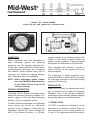
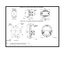
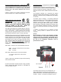
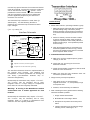
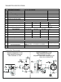
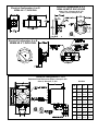
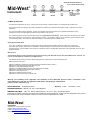
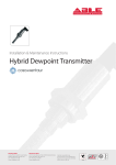
Installation & Maintenance Instructions Model 140 Delta Meter & Model 140 Electrical Reading Office Aberdeen Office Cutbush Park, Danehill, Lower Earley, Reading, Berkshire. RG6 4UT. UK. Tel: +44 (0)118 9311188 Email: [email protected] Unit 6 Airside Business Park, Kirkhill Industrial Estate, Dyce, Aberdeen. AB21 0GT. UK. Tel: +44 (0)1224 725999 Email: [email protected] Internet: www.able.co.uk e-procurement: www.247able.com Registered in England No: 01851002 VAT No: GB 417 2481 61 BULLETIN NO. IM140-02 Mid-West (Supersedes BULLETIN NO. IM140/01) ® Instrument Model 140 "DELTA METER Installation and Operating Instructions INSPECTION Before installation check the nameplate on each instrument against the receiving paperwork and the intended application for correct part number, materials of construction, working pressure, dial range, etc. If equipped with switches, check electrical rating, type of enclosure, etc. Inspect for shipping damage and, if damaged, report it immediately. NOTE - Before attempting repairs contact your local Mid-West Representative or our factory. Failure to do so will void any warranty. PRODUCT DESCRIPTION The Model 140/141 “Series” is a medium range differential pressure instrument available as a switch, a gauge, or both. See “Part Numbering System”, (Fig. 6) for available options. A flexible elastomer diaphragm and calibrated range spring are moved by differential pressure. A pair of magnets, coupled with the diaphragm, transmit this motion through the wall of the pressure housing to a follower magnet attached to an indicating pointer. The rotation of the follower magnet causes the pointer to track movement of internal magnet and indicate the differential on the dial scale. When equipped with switches, a contact is made, or broken, by the magnetic field of the internal magnets. The diaphragm is totally supported upon reaching full travel in either direction, providing full over-range protection to the rated working pressure of the housing. INSTALLATION Model 140/141 “Series” is calibrated and tested prior to shipment and is ready for immediate installation. Use of the following installation procedures should eliminate potential damage and provide optimum trouble-free operation. 1. CONNECTIONS 1/4" FNPT is provided as standard but check paperwork for connections ordered. There are two connections on the housing identified as “hi” and “lo” for high pressure and low pressure. Be sure these get plumbed to the proper connections on your system. Improper connection will not damage the instrument, but it will not function properly. Flexible tubing is recommended to minimize effect of any vibration that may exist. 2. INSTRUMENT LOCATION On liquid service, the instrument should be mounted below the process connections to facilitate self-bleeding. On gas service, it should be located above the process connections to promote self-draining. If the process contains particulates, a “pigtail” loop or drop leg (manometer “U-tube” configuration) in the tubing will minimize the possibility of it migrating into the instrument. 3. PANEL MOUNTING Gauges with 2-1/2" dials can only be mounted through the rear of the panel. Make the proper panel cutout as indicated in (Fig. 5). Remove the (4) bezel screws. Insert the gauge front through the rear of the panel and reinstall the bezel screws through the front of the panel and into the gauge bezel. Tighten the screws securely, alternating in a diagonal pattern. mounting studs, finger tight, into the metal inserts located in the rear of the bezel. Insert the gauge through the panel aligning the panel mounting studs with the holes in the panel. Install the four (4) #8-32 nuts onto the studs and tighten securely. 4. PIPE MOUNTING An optional pipe mounting kit is available for mounting the gauge to a 2" vertical or horizontal pipe. 5. TROUBLE SHOOTING A. Gauge does not indicate differential. i. Check for proper hook up, high to “hi” and low to “lo” ports. ii. Make certain block valves are open and, if using a 3-valve manifold, that the equalizer (balance) valve is closed. iii. If i & ii check out correctly, verify that there is pressure to the instrument. iv. If there is pressure to the instrument, check to determine that there is differential across the unit being monitored. If so, contact the factory for assistance and/or an “RGA” (Return Goods Authorization) number to return the instrument for repair or replacement. B. Gauge accuracy and set point problems: Gauges with 3-1/2" dial must be mounted from the front of the panel. Contact factory for mounting information and dimensional data. i The Gauges with 4-1/2" dial must be mounted from the front of the panel. Make the cutout as shown in (Fig. 5). Insert the four (4) panel ii All others, contact the factory for assistance. Verify gauge is not in an electromagnetic/magnetic environment. i.e.; close proximity to high current power lines. MODEL 140 - 2-1/2 INCH PLASTIC DIAL ASSY. (STANDARD) MODEL 140 - 4-1/2 PLASTIC INCH DIAL ASSY. (OPTIONAL) (Fig. 5) NOTES: 1. Drawings show standard gauge nominal dimensions. (not to scale) 2. Dimensions shown in parentheses are in millimeters. 3. Mounting Dimensions for 3-1/2" & 4-1/2" Alum. Dial Assys. – Contact Factory Manufacturer reserves the right to change specifications without prior notice. All dimensions in inches and millimeters. BULLETIN NO. ELEC-IM140/11A Replaces ELEC-IM140-141/09A Mid-West ® Instrument Model 140 Electrical Installation and Operating Instructions ELECTRICAL Gauges with switches have one or two SPST or SPDT hermetically sealed adjustable set point reed switch assemblies. Resistive load ratings and capabilities for each reed switch type are defined as follows: * Type *Power Max. Current Max. Voltage Setting (F.S.) Hysterisis (Max/Nom) SPST(Norm Open) 25 W 0.5 Amps 240 VAC/VDC 15% to 90% 15% / 8% Full Scale(F.S.) Repeatability 1% F.S. SPDT 3W 0.25 Amps 125 VAC/VDC 15% to 90% 10% / 5% Full Scale(F.S.) 1% F.S. Product of the switching voltage and current shall not exceed the power rating of the device. Provide standard protection techniques for the switch contacts for capacitive and inductive loads. Use current limiting techniques near the switch to protect the contacts due to high inrush (i.e.; in line resistor or inductor) for long cable interfaces. Provide clamping devices at or near inductive loads (i.e.; relay). Long cable runs can be considered both inductive and capacitive, therefore also clamp across the switch. We recommend for long cable runs of 70 feet or greater that you use the SPST switch or use a current limiting resistor wired in series and located near the switch. Contact the factory if you need assistance. Please note that the SPST switch is available in only the Normally Open configuration Both switch types are field adjustable from 15% to 90% of full scale reading of the gauge.. All switches come with a decal to identify adjustment direction to increase the set point. To set the switch at a desired set point on increasing pressure apply pressure to the gauge for the desired set point. Adjust the switch so that it is adjusted above the set point (normally open contacts are open) and slowly decrease the set point until the switch activates (normally open contact closes). Remove pressure and slowly reapply to determine the actual setting. This process can be repeated to achieve a more accurate setting. All switch functionalities shown are with the gauge at 0 PSID. The SPST switches are available in the Normally Open configuration only. Use the Mid-West Power Relay 1000TR or equivalent relay for loads above the switch rating. The following warnings apply to all gauge options with electrical interface. WARNING: ELECTRICAL CONNECTIONS SHOULD BE PERFORMED BY QUALIFIED PERSONNEL AND MEET THE REPRESENTATIVE COUNTRY'S NATIONAL ELECTRICAL CODE. WARNING: FAILURE TO CONNECT TO THE PROTECTIVE CONDUCTOR TERMINAL MAY RESULT IN A SHOCK HAZARD. WARNING: REMOVAL OR REPLACEMENT OF INSTRUMENT HARDWARE VOIDS ALL WARRANTIES AND CONFORMANCES TO ANY STANDARDS (EXCEPT COVERS AND OR SWITCH ADJUST PLUGS). NEMA 4X (Plastic Weatherproof Enclosure) (A & B options) The reed switch(es) are located inside the enclosure, on the top of the pressure housing, and are connected to a 7 position terminal strip. An opening is provided at the rear of the enclosure for a 1/2" flexible weather-proof cable or conduit connector (supplied by customer). Upon request the hole may be sized to accommodate a PG-11 cable gland connector. Remove the switch enclosure cover by removing the (4) screws. Insert wires through an appropriate (not supplied) weatherproof connector into the enclosure and connect to the terminal strip per the terminal strip diagram shown below or on the underside of the switch enclosure cover. The center connection is for connection of a protective conductor and is connected to the body of the pressure gauge. Gauge Front NO NC CM SINGLE CM NC NO DOUBLE The terminal strip will accept wires in the range of 22 Awg 16 Awg.. Reinstall the cover, gasket, and (4) screws. (Fig. 3) after connection of field wiring. Wiring for the SPST switches is connected between NO and CM connections on the terminal strip. Normally closed switches are not available. Access holes and plugs are provided for external adjustment of the switches if required. Division II Hazardous Ratings (E ,F, & W) options): Transmitter Option: (T & W ) Electrical Configuration) rd The E, F, & W Electrical Configurations are 3 party certified to both Canadian and U.S. standards for Class I, Division II, Groups A, B, C, & D, Class II, Groups F & G hazardous environments The Model 140/141 Transmitter is intended for use in General Purpose Locations (T electrical configuration) or Division 2 locations (W electrical configuration). In both cases the enclosure carries a NEMA 4X IP65 environmental rating. Interface is identical to the plastic weatherproof enclosure with the exception of a ½” FNPT conduit interface. NEMA 7 (Explosion-proof ) Enclosure (C & D options) WARNING: THE COVER AND/OR SWITCH ADJUST ACCESS PLUGS MUST NEVER BE REMOVED WHEN THERE IS POWER TO THE UNIT. MAKE ALL ADJUSTMENTS IN A NONHAZARDOUS AREA. The gauge and switches are mounted inside the enclosure. A 1/2"-14 FNPT conduit connection is provided in the bottom side of the enclosure. A proper explosion proof, dust tight sealing fitting with appropriate sealing cement must be used when making connections to the 24", 18 Awg. wire leads. Adjustment of the set point can be accomplished by removing the switch adjustment access plug(s). Insert the screw driver through the hole into the switch adjustment slot and rotate until the desired set point is reached. A clockwise rotation will increase the set point for the right side switch access and a clockwise rotation will decrease the set point for left switch access. Do not use excessive force. Reinstall the access plugs for 5 full threads of engagement after completion. The transmitter assembly as a component has passed numerous European EMC standards (ie; Compliance to IEC EN61326). Contact the factory if additional low pass filtering is necessary. The Model 140/141 indicating / non-indicating differential pressure transmitter is a 2 wire loop powered microprocessor based 4-20 ma transmitter. The magnetic angle sensor & electronics senses the angle (relative to the transmitter sensor) of the magnet which moves linearly in the bore. Each transmitter is individually calibrated to the gauge using an 11 point calibration linearization technique. This method results in a <2% full scale accuracy for the upper 80% of the range. In addition, an external zero pin is available for simple remote zeroing (instead of supplied local zero) after installation. Caution: Do not attempt to reposition the transmitter assembly within the enclosure. This voids the warranty and will “knock” the unit out of calibration. Disassembly and reassembly of any internal process parts will also require the unit to be re-calibrated. Calibration must be performed at the factory. SPDT Switch leads are color coded and labeled as follows: White- 1 or 2 Com (1 Right Access 2 Left Access) Black- 1 or 2 NC Red - 1 or 2 NO SPST Switch leads are black in color and are labeled: 1 or 2 Com (1 Right Access 2 Left Access) 1 or 2 NO Figure 4 Zero Zero Switch Return Enclosures with SPDT and SPST switches comply with NEC Class 1, Groups C & D, Class 2 Groups E, F, & G, NEMA 7 & 9, and are CSA & UL listed. 8-28 Vdc A green / yellow wire is provided for proper electrical bonding of the enclosure chassis. The weather-proof enclosure comes standard with a ½” FNPT conduit interface. Internal to the enclosure is a 4 position terminal strip. The terminal strip accepts wire sizes 22 AWG – 16 AWG. Connections are defined in Figure 4. Connect loop power between the connections labeled 8-28 Vdc and RTN. Connect the protective conductor wire to the terminal with the symbol. A zero pushbutton is also included. Zero the transmitter with the transmitter powered and no differential pressure applied by depressing the switch for a minimum of 2 seconds. The maximum loop resistance is 1000 ohms (@ 28Vdc Input). Use the following formula to determine the maximum loop resistance at other input voltages: ((Vs – 8) *1000)/ 20 Interface Schematic Customer Interface DP Transmitter To Transmitter 8-28 Vdc Pin 3 3 RLoop 3 To Transmitter Zero Pin 2 8-28Vdc 2 2 1 4-20 ma To Transmitter GND Pin 1 1 1 Zero switch not present for hazardous locations product 2 Optional remote zero (customer supplied) 3 Loop Resistor can be located in the ground leg The interface schematic shows an implementation of the Remote Zero function. The supplied unit incorporates an internal pushbutton for zeroing the unit locally (non-hazardous locations only "T" electrical configuration). Occasionally the transmitter may require a “re-zero” . The “re-zero” may be necessary due to stray magnetic fields or a large change in temperature from when the unit was originally calibrated. Warning: If zeroing in the Hazardous Location environment use a switch approved for that location. Trouble Shooting 1. Switch doesn't function. (Assuming Indication is good) i. Make sure that the switch load does not exceed the specified wattage rating of the switch. (steadystate and transient). Contact factory for assistance for excessive loads, otherwise proceed to the next step. ii. Perform a continuity check of the switch contacts by trying to actuate the switch using an external magnet. An operational switch usually indicates a problem with the gauge. If not operational proceed to the next step. iii. Verify the reed switch wires are connected to the terminal strip (NEMA 4X enclosure only). Contact the factory for assistance if the switch is connected and/or request an "RGA" number. 2. Transmitter doesn't function A. Make sure you have supplied power (proper voltage) to the unit. B. Check that you are wiring to the correct Interface terminals. C. Check the transmitter interfaces to the terminal board for loose connections. D. Make sure that the loop resistance does not exceed the specified rating. 3. Gauge accuracy and set point problems: i. Verify gauge is not in an electromagnetic / magnetic environment. i.e.; close proximity to high current power lines. ii. All others, contact the factory for assistance. 4. When contacting the factory please have the following information available if possible: 1. Gauge / Switch Serial Number Occasionally the transmitter may require a “re-zero” . The “re-zero” may be necessary due to stray magnetic fields or a change in temperature from when the unit was originally calibrated. 2. Model Number of the Gauge / Switch 3. Description of the problem and events prior to failure. 4. Interface Information such as switching voltage, switching current, cable lengths, etc. TRANSMITTER SPECIFICATIONS: Transmitter Specifications: (Calibrated on Increasing pressure) Differential Pressure Range 0-50” H2O to 0 -100 PSID Leakage None Hi to Lo Comments: Pressure (Ratings) Max Working See Specifications ASME B40.100 GRADE B Gauge Accuracy 2% Operating Temperature (Max.) -20 F - 150 F ELECTRICAL: Min Typ 2% Transmitter Accuracy (FSR) Supply Voltage (3) (Vdc) Max 8 28 Upper 80% of Full Scale Range Pin 3 Reverse Polarity Protected Output Current (ma) Zero Floating (2) 4.0 – 20.1 ma Zero Time (seconds) 4.8 Pin 2 6.3 2 1000 Max Loop Resistance (ohms) Max Loop Resistance Formula 4.0 – 22.0 8 Zeroed (1 connected to 2) Voltage (Pin 2 to 1) 4.0 – 21.0 ((Vs – 8)*1000)/ 20 INTERFACE: Electrical: Environmental Rating: 4 Position Terminal Strip; ½” NPT Conduit 1= Rtn, 2= Zero, 3 = 8-28 Vdc In 4= Chassis NEMA 4X Certifications: CSA (Canadian & US Standards; Division 2 Locations) Connections: 22 Awg – 16Awg Wire Transmitter Dimensional Electrical Configuration: T or W Model 140/141 End Connected With Transmitter 2 ½” Dial Electrical Configuration: T or W Model 140/141 End Connected With Transmitter 4 ½” Dial W option= Class I, Div. 2, Groups A, B, C,D Class II, Div 2, Groups F & G Electrical Configuration: A or B NEMA 4X 2 ½ INCH DIAL Electrical Configuration: E or F NEMA 4X METAL ENCLOSURE Class I, Div. 2, Groups A, B, C,D Class II, Div 2, Groups F & G Electrical Configuration: A or B NEMA 4X 4 ½ INCH DIAL Electrical Configuration: C or D Explosion-Proof Enclosures Class I, Groups C & D Class II, Groups E, F, & G Dial Size DIM 2½ 2½ 4½ A 7.12 (180.9) 6.53 (163.3) 8.50 (215.9) B 4.15 (105.4) 2.12 (53.84) 2.50 (62.5) C 3.15 (80.01) 3.12 (79.24) 4.35 (110.5) D 6.00 (152.4) 6.56 (166.6) 6.25 (158.8) E 8.75 (222.2) 7.75 (196.9) 9.12 (231.6) F 7.35 (186.7) 6.68 (169.7) 7.75 (196.9) G 3.80 (96.52) 3.80 (96.52) 3.80 (96.52) 8.12 (206.3) 7.43 (188.7) 7.75 (196.9) H BULLETIN NO. ELEC-IM140/11A Replaces ELEC-IM140-141/09A Mid-West ® Instrument CE Marking Statements: The Electrical Configurations A,B, E, & F of this product are CE marked in compliance with the Low Voltage Directive to EN-61010-1. These products shall not be placed in an Explosive atmosphere as defined by the ATEX Directive 94/9/EC except if evaluated to be “Simple Apparatus”. They may be classified as simple apparatus. However, the evaluation to the relevant portions of the applicable standards and clearly identifying the product as simple apparatus shall be the responsibility of the end user. The Pressure Equipment Directive has been determined to be non applicable for CE marking. These products are manufactured in accordance with article 3, paragraph 3 of the directive, “sound engineering practice”. They fall below category I for non-hazardous gases, hazardous liquids, & non-hazardous liquids. This product also falls below category I for hazardous gases at or below 200 bar. Simple Apparatus NEC 504.2 The A, B, E, & F Electrical configurations of this product meet the simple apparatus definition as defined in NEC 504.2 of Article 504 (Intrinsically Safe Systems). Because of this classification, equipment listing is not required (504.4) and ordinary wiring methods shall be permitted (504.20). Proper installation of this product in a hazardous location to the applicable requirements is the responsibility of the end user / equipment installer. EMC Directive: The transmitter design has been evaluated to and passed the following “EN” Standards as they relate to the EMC directive. However, the units are not CE marked for compliance to the EMC directive. IEC EN61326:1997 Environment Industrial, Electrical Equipment for measurement, Control and Laboratory use, EMCrequirements from which: EN55011:1998Emission standard for Industrial, Scientific and Medical Equipment, Class A EN61000-4-2:1995 Electrostatic discharge (ESD) immunity EN61000-4-3:1996 Radiated EM field immunity ENV50204:1995 Radiated EM field immunity from digital telephones (GSM) EN61000-4-4:199 5Electrical fast transient (EFT) immunity EN61000-4-5:1995 Surge immunity EN61000-4-6:1996RF conducted immunity EN61000-4-8:1993 Power Frequency magnetic field Warning: The suitability of the application and installation of this differential pressure switch / transmitter is the responsibility of the end user. The applicable certifications, listings apply to the differential pressure switch / transmitter only. PROOF PRESSURE: 2X Working Pressure WORKING PRESSURE: 3,000 PSI (AL, SS) 1500 PSI (Brass) Warranty: 5 Years Transmitter (1 Year) TEMPERATURE LIMITS: -40F to + 200F (Switch Options); -20 F TO + 150 F (Transmitter Option) These limits are based on the entire instrument being saturated to these temperatures. System (process) temperatures may exceed these limitations with proper installation. Contact our customer service representative for details. Mid-West Instrument 6500 Dobry Dr. Sterling Heights, MI 48314 (586)254-6500 FAX (586)254-6509 E-Mail: [email protected] Web Page: www.midwestinstrument.com