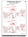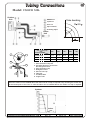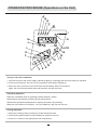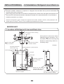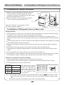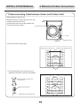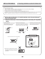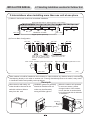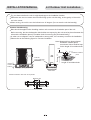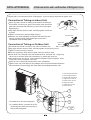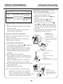
1
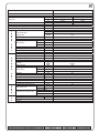
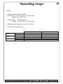
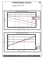
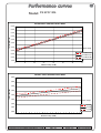
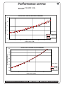
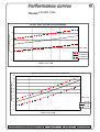
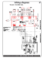
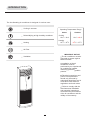
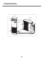
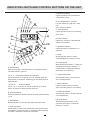
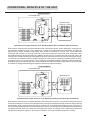
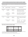
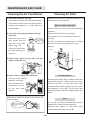
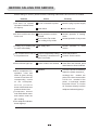
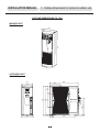
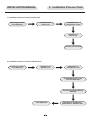
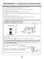
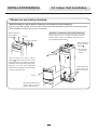
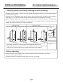
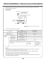
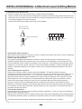
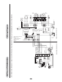
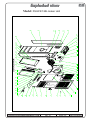
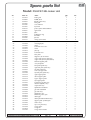
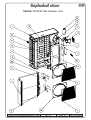
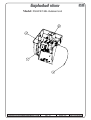
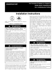
Technical Service Manual
SERIES: FS KFR120L
Free Standing
AM
C
FM
1
2
AUTO
FM
REFRIGERANT
R407C
Rev.:
01
ELECTRA CONSUMER PRODUCTS LTD
HEAT PUMP
Date:
Rev.: 01
29/02/04
Series: FS
Date: 20/02/2004
FS 1200
Model
Installation method
Characteristic
Wall mounted
Units
Kcal/hr
Btu/hr
W
W
W/W
Capacity
Total input
COP/EER
Power supply (voltage, cycle)
Circuit breaker rating
I
N
D
O
O
R
Noise Power
Condensate drain tube I.D
Dimensions
U
N
I
T
O
U
T
D
O
O
R
U
N
I
T
T
U
B
E
S
A
C
C.
W
D
H
Weight
Package dimensions
Units per palet
Height stacking
Refrigerant control
Compressor type & model
Fan type & qty.
Fan speed - HI
Airflow
Noise Power
Dimensions
Weight
Packing dimensions
Height stacking
Units per palet
Refrigerant
Charge
Condensate drain tube I.D
Tube size O.D
Connection between units
W
D
H
RPM
3
m /hr
(CFM)
dBA
mm
mm
mm
mm
Kg
mm
units
units
RPM
m /hr
(CFM)
dBA
mm
mm
mm
Kg
mm
units
units
gram
mm
liquid
in.
suction
in.
Indoor-Outdoor
height difference
tubing length
Operation control type
Heating elements
Ducts
Others
ELECTRA CONSUMER PRODUCTS LTD
Heating
12800
51200
15000
4567
2.86
400/50/3
3X16
Centrifugal
A
Fan type & qty.
Fan speed (HI)
Airflow (HI)
Cooling
11000
44000
12900
4824
2.55
2000
1177
52 / 56
25
600
370
1900
70
2000*710*490
4
1
R-407C
SCROLL HR61YAB LG
AXIAL X 2
1125
4200
(2470)
69
900
340
970
95
985*406*1016
2
6
R407C
3750
16
3/8
3/4
MAX. 20m
MAX. 40m
Operation by hand on LCD
W
Rev.: 01
Series: FS
Date: 20/02/2004
NOTES:
1. Rating conditions ISO/CD 13253R
Cooling: indoor: 27°C (80°F) DB 19°C (66°F) WB
Outdoor: 35°C (95°F) DB
Heating: indoor: 20°C (68°F) DB
Outdoor: 7°C (45°F) DB 6°C (43°F) WB
Refrigerant tubing length (one way) 7.5m (24.6 ft)
2. Guaranteed operating range:
Cooling
Heating
Voltage
Upper limit
Lower limit
Upper limit
Lower limit
1 PH
3 PH
ELECTRA CONSUMER PRODUCTS LTD
Indoor
32°C DB, 23°C WB
21°C DB, 15°C WB
27°C DB
20°C DB
Outdoor
46°C DB
21°C DB
24°C DB, 18°C WB
-9°C DB, -10°C WB
198 – 242 V
360 – 440 V
Rev.: 01
Series: FS
Date: 20/02/2004
FS KFR 120L /OU10-50 R407C
ELECTRA CONSUMER PRODUCTS LTD
Rev.: 01
Series: FS
Date: 20/02/2004
Model: FS KFR 120L
FS1200T R407c COOLING CAPACITY
18,000
17,000
Indoor Temp.
CAPACITY [W)
16,000
30 C DB/50%RH
26 C DB/50%RH
15,000
23 C DB/50%RH
14,000
13,000
12,000
11,000
10,000
10
15
20
25
30
35
40
45
Outdoor Tem p. (C DB)
FS1200T R407c HEATING CAPACITY
21,000
18,500
CAPACITY [W)
16,000
13,500
Indoor Temp.
11,000
20 C DB
8,500
18 C DB
15 C DB
6,000
-10
-5
0
5
10
15
Outdoor Tem p. (C DB)
ELECTRA CONSUMER PRODUCTS LTD
Rev.: 01
Series: FS
Date: 20/02/2004
Model: FS KFR 120L
FS1200T R407c COOLING TOTAL INPUT
6,500
6,000
5,500
TOTAL INPUT (W)
5,000
4,500
4,000
3,500
Indoor Temp.
3,000
30 C DB/50%RH
2,500
26 C DB/50%RH
2,000
23 C WB/50%RH
1,500
10
15
20
25
30
35
40
45
Outdoor Tem p. (C DB)
FS1200T R407c HEATING TOTAL INPUT
6,500
6,000
TOTAL INPUT (W)
5,500
5,000
4,500
4,000
Indoor Temp.
3,500
20 C DB
18 C DB
3,000
15 C DB
2,500
-10
-5
0
5
10
15
Outdoor Tem p. (C DB)
ELECTRA CONSUMER PRODUCTS LTD
Rev.: 01
Series: FS
Date: 20/02/2004
Model: FS KFR 120L
FS1200T R407c COOLING DISCHARGE PRESSURE
30.0
DISCHARGE PRESSURE [Bar(g
25.0
20.0
15.0
Indoor Temp.
30 C DB/50%RH
10.0
26 C DB/50%RH
23 C DB/50%RH
5.0
10
15
20
25
30
35
40
45
Outdoor Tem p. (C DB)
FS1200T R407c HEATING SUCTION PRESSURE
5.00
SUCTION PRESSURE [Bar(g)
4.50
4.00
3.50
3.00
Indoor Temp.
2.50
20 C DB
2.00
18 C DB
15 C DB
1.50
-10
-5
0
5
10
15
Outdoor Tem p. (C DB)
ELECTRA CONSUMER PRODUCTS LTD
Rev.: 01
Series: FS
Date: 20/02/2004
Model: FS KFR 120L
FS1200T R407c COOLING SUCTION PRESSURE
5.5
SUCTION PRESSURE [Bar(g)
5.0
4.5
4.0
Indoor Temp.
30 C DB/50%RH
3.5
26 C DB/50%RH
23 C DB/50%RH
3.0
10
15
20
25
30
35
40
45
Outdoor Tem p. (C DB)
FS1200T R407cHEATING DISCHARGE PRESSURE
24
23
DISCHARGE PRESSURE [Bar(g
22
21
20
19
18
Indoor Temp.
17
20 C DB
16
18 C DB
15
14
-10
15 C DB
-5
0
5
10
15
Outdoor Tem p. (C DB)
ELECTRA CONSUMER PRODUCTS LTD
Rev.: 01
Series: FS
Date: 20/02/2004
Model: FS KFR 120L
ELECTRA CONSUMER PRODUCTS LTD
Rev.: 01
Series: FS
Date: 20/02/2004
HEAT PUMP MODELS
SERIES: FS KFR 120L
ELECTRA CONSUMER PRODUCTS LTD
Rev.: 01
Series: FS
Date: 20/02/2004
Tubing Connections
Model: FS KFR 120L
Outdoor
Unit
Suction line
Outdoor
Unit
Tube bending
Liquid line
Suction line
Tube bending
R 3.5
Flare nut
Liquid line
Pipe insulation
R 3.5
Flare nut
Insulating sleeve
Pipe insulation
Indoor
Insulating sleeve
Unit
R
Indoor
Unit
R
Tube (Inch)
1/4”
3/8”
1/2”
5/8”
3/4”
TORQUE(N.m.)
2
1
FLARE NUTS
11-13
40-45
60-65
70-75
80-85
VALVE CAP
13-20
13-20
18-25
18-25
40-50
SERVICE PORT CAP
11-13
11-13
11-13
11-13
11-13
Tightening Torque Values
3
4
5
7
6
8
1. Valve Protection Cap-end
2. Use Allen Wrench to open/close
the Refrigerant Valve
3. Valve Protection Cap
4. Refrigerant Valve
5. Service Port Cap
6. Flare Nut
7. Unit Back Side
8. Copper Tube
When the outdoor unit is installed above the indoor unit an oil trap is required every 5m along the suction line
at the lowest point of the riser. In case the indoor unit is installed above the outdoor no trap is required.
Outdoor
:
Indoor
ELECTRA CONSUMER PRODUCTS LTD
Rev.: 01
Series: FS
Date: 20/02/2004
ELECTRA CONSUMER PRODUCTS LTD
Rev.: 01
Series: FS
Date: 20/02/2004
Free Standing Air Conditioner
AM
C
FM
1
2
AUTO
FM
Operation Instructions & Installation Manual
Operation Instructions
Page
Introduction
1
System Description
2
Operation Modes, Functions and Features
3
Indicator Lights of the Indoor Unit and Control
Buttons on the Unit
5
Operational Principal of the Unit
6
Specifications and Technical Parameters
7
Operation Procedure (Operations on the Unit)
8
Turning on the Air Conditioner
8
Ventilating Operation
8
Cooling Operation
8
Cooling Operation with Auto Fan Mode
9
Heating Operation
9
Heating Operation With Auto Fan Mode
9
Dry Operation
9
Temperature Selecting
9
Sleep Function
10
Timer Function
10
Operation Modes for Timer Function
10
Air Direction Control
12
Turning Off
12
Lock Function
12
Protection Modes and Instructions for Service
Electric Heater
13
Maintenance and Care
14
Operating Tips
15
Preventive Measures
16
Before Calling For Service
18
If your air conditioner is for
cooling only, please
disregard the heating
instructions.
Please read these instructions
before operating the air
conditioner.
The change of function
parameters and circuit
diagram will not be notified;
please refer to the nameplate
and the circuit diagram on
the unit.
Installation Instructions
Page
1. Outline Dimensions for Indoor & Outdoor Unit
19
2. Installation Process Chart
20
3. Installation of Indoor Unit
21
3.1 Selecting Location for Indoor Unit Installation
21
3.2 Indoor Unit Installation
22
3.3 Refrigerant Line Installation
24
3.4 Drain Line Installation
24
3.5 Electrical Cable Connections
27
4. Outdoor Unit Installation
29
4.1 Selecting Location for Outdoor Unit Installation
29
4.2 Outdoor Unit Installation
31
4.3 Interconnection and leak detection of Refrigerant Line
32
4.4 System Installation
33
4.5 Electrical Layout and Wiring Method
34
4.6 Test Operation
36
4.7 Drain Condensing Water
(used only by heat pump unit)
37
5. Wiring Diagram
38
INTRODUCTION
The free Standing air conditioner is designed for various uses:
Cooling in summer
Operating Temperature Range
Indoor
Dehumidifying at high humidity conditions.
Outdoor
Cooling
16 oC ~ 30 oC
10 oC ~ 46 oC
Heating
16 oC ~ 30 oC
Heating
-10oC ~ 21oC
Air Filter
IMPORTANT NOTICE:
Ventilation
The air conditioner must be
grounded to protect against
electrical shock.
Installation of the air
conditioner must be
performed by an experienced
air conditioning installer,
observing good refrigeration
practice.
AM
C
FM
1
2
FM
AUTO
Electrical connections and
power cord replacement
should only be made by
authorized electricians and in
accordance with electrical
regulations and local codes.
Failure to comply with the
manufacturer s installation
and operation instructions
could affect the performance
of the air conditioner and the
validity of the warranty.
SYSTEM DESCRIPTION
Indoor Unit
Outdoor Unit
Air In
Air Out
Air Outlet
AM
C
1
2
FM
AUTO
FM
Control Panel
Air Out
Air Out
Air Inlet
Air In
Drain Tube
Interconnecting Lines
OPERATION MODES, FUNCTIONS AND FEATURES
This series of conditioners have the following functions:
COOL
HEAT
Cools, dehumidifies and filters the room air. Maintains desired room
temperature.
Heats and filters the room air. Maintains the desired room temperature.
Automatically switches from COOLING to HEATING or from HEATING to
AUTO
COOLING, maintaining the desired temperature according to the room
conditions.
DRY
Decreases humidity of atmosphere and maintains the room temperature. It
is suitable to use in dankish and rainy season.
FAN
Recirculates and filters the room air. Maintains constant air movement in the
room.
The air conditioner automatically selects the fan speed according to the
AUTO FAN
room temperature. At the start, the unit operates at high fan speed. As the
room air approaches to the set temperature, the fan switches automatically
to a lower speed for quieter operation.
In HEATING and in AUTO FAN, the fan will be turned off when the
HOT KEEP
compressor is not in operation and will not be restarted, unless the indoor
coil reaches adequate temperature. This HOT KEEP feature prevents
uncomfortable cold air drafts. Use of AUTO FAN is, therefore, recommended
when the air conditioner is in HEATING mode.
TIMER
Real time control and display, automatically turns the air conditioner ON and
OFF according to the time of day setting, ensuring comfort conditions before
returning home, without wasting electricity. It turns the air conditioner off
automatically when sleeping.
SLEEP
Designed to create comfortable sleeping conditions. When in cooling mode,
the temperature rises one-degree centigrade after each consecutive hour,
up to three hours, from the start of the mode. The rising temperature
prevents the feeling of over-cooling while sleeping (when your body is at
rest). In heating mode the reverse occurs; the air conditioner lowers its
temperature one-degree every hour. When in sleeping mode, air conditioner
will be automatically turned off after operating for seven hours. The result is
a more comfortable and invigorating sleep, which leaves you feeling fresh
and energetic on the next morning.
OPERATION MODES, FUNCTIONS AND FEATURES
FILTER
INDICATOR
Filter indicator on the indoor unit display is turned on when when the filter
requires cleaning. After cleaning and reinstalling the filter. The system
should be reset.
3-MIN.
DELAYED RNU
The compressor is protected by a three-minute delayed restart.
MEMORY
The microprocessor retains the last data entry whether or not the unit is
plugged in. Therefore, when the unit restarts after a power distruption or
failure, it will resume operating in the same mode as before the power was
disrupted.
LOCK
Freezes the last operation setting on the remote control. When LOCK is
activated, the remote control will the be able to control the air-conditioner.
INDICATOR LIGHTS AND CONTROL BUTTONS ON THE UNIT
A. Stand-by Indicator
Lights up when the air conditioner is
connected to power.
A
E
D
C
B. Fan Speed Button: To select
M
I
IONIZER
POWER RUN FILTER TIMER RESET
AM
C
H
J
1
G
FM
2
AUTO
D. Filter Indicator
Lights up to remind you that the filter
needs to be cleaned.
FM
FAN SPEED
TEMP
L
LCD
K
B
SET
HR
F
ON/OFF
TIMER
CLEAR
MODE
SWING
N
V
O
SLEEP
LOCK
P
T
Low Fan / Mid Fan / High Fan / Auto
Fan.
Four modes for option
C. Timer Indicator
Lights up when the unit is proceeding
timer mode.
S R
E. Operation Indicator
Lights up when the conditioner is in
operation.
F. Mode
By pressing the button to select
Cool/Heat/Dry/Auto Fan/Auto mode.
Q
M. Reset Button
After cleaning filter, press this button to reset filter function.
The filter indicator goes out.
"N" &" V" Power Switch Button and Indicator
Press this button to set power on or off. Indicator lights up
when power is connected. Indicator goes out when power is
disconnected.
"O"/"Q"/"P"
Clock Set Button
Press "O" or "P" button to decide clock time up or down.
Press "Q" button to cancel present clock set.
R. Air Swing Button
Press this button to decide if vertical air swing will be working
or not.
S. Sleep Button
Decide whether or not to proceed sleep operation mode.
T. Self-Lock Button
All set modes or status are locked after pressing this button.
Cancellation of self-lock button is necessary when adjusting
set status, otherwise it cannot be proceeded.
G. Ionizer Button
When pressing this button, "I "lights up
indicating that ionizer is working ; "I"
indicator does not light up indicating
that ionizer is not working.
H. Temperature Button
Pressing the button to decrease the
set room temperature.
I. Ionizer Indicator
Lights up when ionizer is working.
Goes out when ionizer is not working.
J. Temperature Button
Pressing the button to increase the set
room temperature.
L/K.Timer Button
When pressing the button, to set
operation time longer or shorter by
pressing "L" button.
OPERATIONAL PRINCIPLE OF THE UNIT
HEATING MODE
OUTDOOR UNIT
Suction
Serviceaccumulator
port
INDOOR UNIT
Senssor
Indoor coil
Compressor
Senssor
Reverse
valve
Valves
Flared
connection
Capilary
tube
Main
Capilary
tube
Strainer
Outdoor coil
Strainer
Check Strainer
valve
Operational Principle Chart for Free Standing Room Air Conditioner with Heat Pump
Both outdoor unit and indoor unit start operation after connected to power. When operating in cooling mode,
low-pressure refrigerant vapour from evaporator of indoor unit is absorbed into compressor and become
high-pressure vapour through compressing; after entering condenser of outdoor unit, it proceeds heat
exchange with outdoor air through axial fan to become refrigerant liquid and enter evaporator after
decreasing pressure and temperature by capillary throttle; then to proceed heat exchange with indoor air
needing to be conditioned through centrifugal fan of indoor unit and become low-pressure refrigerant vapour;
in such way to circulate in circles to reach the purpose of cooling. When operating in heating mode, by action
of selector valve on four-way electric valve, refrigerant proceeds circulation against cooling procedures.
Refrigerant gives out heat through room heat exchanger and absorbs heat through outdoor heat exchanger
to operate in heating circles through heat pump to reach the purpose of heating.
COOLING MODE
OUTDOOR UNIT
Suction
Serviceaccumulator
port
INDOOR UNIT
Senssor
Indoor coil
Compressor
Senssor
Reverse
valve
Outdoor coil
Strainer
Valves
Capilary
tube
Check
valve
Flared
connection
Main
Capilary
tube
Strainer
Strainer
Operational Principle Chart for Free Standing Cooling Only Room Air Conditioner
Both outdoor unit and indoor unit start operation after connected to power. Low-pressure refrigerant vapour
from heat exchanger of indoor unit is absorbed into compressor and become high-pressure vapour through
compressing; after entering heat exchanger of outdoor unit, it proceeds heat exchange with outdoor air to
become refrigerant liquid and enter heat exchanger of indoor unit after decreasing pressure and temperature
by capillary throttle; then to proceed heat exchange with indoor air needing to be conditioned and become
low-pressure refrigerant vapour; in such way to circulate in circles and reach the purpose of cooling.
OPERATION PROCEDURE (Operations on the Unit)
A
E
D
C
M
I
IONIZER
POWER RUN FILTER TIMER RESET
AM
C
H
J
1
G
FM
2
AUTO
FM
FAN SPEED
TEMP
L
K
LCD
B
SET
HR
F
ON/OFF
TIMER
CLEAR
MODE
SWING
N
V
O
SLEEP
LOCK
P
T
S R
Q
Turning on the Air Conditioner
1. Connect the unit to the power supply, indicator A lights up, indicating that the unit is ready for operation.
2. Press N (on/off) button, the unit now is in operation and indicator E lights up.
3. When the unit is turned off, the unit will save the last setting. When it is turned on
again, the unit will automatically start and operate in the last set mode.
Ventilating Operation
Select the ventilating mode by pressing F(mode selection) button.
Select desired fan speed by pressing B (fan speed) button.
Different fan speed will be displayed on display panel after each pressing.
Below are four modes for fan speed : low fan, middle fan, high fan and auto fan
Cooling Operation
1. Select the cooling mode by pressing F (mode selection) button.
2. Press B (fan speed) button to select desired fan speed or auto fan.
3. Press H or J button to set appropriate room temperature.
OPERATION PROCEDURE
Cooling Operation with Auto Fan Mode
This operation starts with the highest airflow in order to lower the room temperature quickly. Then it will
automatically switch to a lower airflow to maintain the set temperature.
Heating Operation
1. Select "Heating" by pressing F (mode selection) button.
2. Press B (fan speed) button to select desired fan speed or auto fan.
3. Press H or J button to set appropriate room temperature.
Heating Operation with Auto Fan Mode
This operation starts with the highest airflow in order to raise the room temperature quickly. Then it will
automatically switch to a lower airflow to maintain the selected temperature. Heating operation with auto fan
mode will automatically provide you a cold air preventive function. The fan will be turned off when temperature
of indoor heat exchanger is very low , preventing uncomfortable cold air drafts.
Dry Operation
Select the Dry mode by pressing mode button (F). Select the suitable temperature setting. While in Dry mode,
the air conditioner will operate at low fan speed, regardless of the fan setting on the Liquid Crystal Display
(LCD) operation display. The fan will operate intermittently to prevent over cooling.
Temperature Selecting
Press TEMP buttons (H) or (J) to change the temperature setting on the Liquid Crystal Display (LCD) of the
display panel. The temperature setting is shown in centigrade degrees. The number indicates room
temperature.
OPERATION PROCEDURE
Sleep Function
Press Sleep button (S) to select the Sleep function. After Sleep function is activated, air conditioner will be
automatically turned off after 7 hours. If Timer function is also activated, the air conditioner will be turned on or
off according to Timer setting.
Press one of the following buttons to cancel Sleep function:
ON/OFF button (N)
SLEEP button (N)
Timer Function
Press Timer button (K) to activate Timer operation . After each pressing Timer button, one of the
following four operation modes will be displayed on LCD display. Timer operation mode appears in arrow
directions in turn and indicator on the unit will light up when Timer function is in operation.
Note: After a power failure (when the unit in Timer mode), the unit will be automatically turned to stand-by mode
and the Timer operation will be cancelled. To resume the use of Timer function, follow the above instructions
Operation Modes of Timer Function
Four operation modes are available:
T1: timing of the first time everyday; T2: timing of the second time everyday; T1wk: timing of Saturday; T2wk
timing of Sunday.
T1 and T2 are two everyday timings, representing different time periods. Such time period will be repeated
everyday.
T1wk and T2wk are the timing of the weekend. The timer indicator lights up when timer is activated. T1wk is
only used for Saturday's timing and is valid only at that day, T2wk is only used for Sunday's timing and is
valid only at that day.
The everyday timing will be turned off when operating at the weekend. The WK timer must be activated before
every weekend.
1. T1 the first time timing startup and closedown everyday
This mode enable you to set the operation time, refer to figure 1
A) Press timer button (K) to select T1, T1 blinks.
B) Press "SET" button (L) , "ON" will appear.
C) Press up and down button (O) & (P) respectively to adjust start time of operation.
D) Press "SET" button (L) again to activate timing start function, "OFF" will appear at the same time.
E) Repeat step (c) to set the closedown time.
F) Press "SET" button (L) to activate timing closedown function. The buzzer will sound and end the timing
setting.
ON
ON
OFF
L
L
2. T2 the second time timing startup and closedown everyday
This mode enables you to set the operation time, refer to figure 2.
A) Press timer button (K), T2 will appear and blink.
L
OPERATION PROCEDURE
B) Press "SET" button (L), "ON" will appear.
C) Press up and down button (O) & (P) respectively to adjust start time of operation.
D) Press "SET" button (L) again to activate timing start function, "OFF" will appear at the same time.
E) Repeat step (c) to set the closedown time.
F) Press "SET" button (L) to activate timing closedown function. The buzzer will sound and end the timing
setting.
ON
ON
OFF
L
L
L
3. T1wk timing of Saturday
This mode enables you to set the operation time, refer to figure 3.
A) Press timer button (K) to select T1wk, T1wk blinks.
B) Press "SET" button (L), "ON" will appear.
C) Press up and down button (O) & (P) respectively to adjust start time of operation.
D) Press "SET" button (L) again to activate timing start function, "OFF" will appear.
E) Repeat step (c) to set the closedown time.
F) Press "SET" button (L) to activate timing closedown function. The buzzer will sound and end the timing
setting.
ON
ON
OFF
WK
L
WK
L
WK
L
4. T2wk timing of Saturday
This mode enables you to set the operation time, refer to figure 4.
A) Press timer button (K) to select T2wk, T2wk blinks.
B) Press "SET" button (L), "ON" will appear.
C) Press up and down button (O) & (P) respectively to adjust start time of operation.
D) Press "SET" button (L) again to activate timing start function, "OFF" will appear.
E) Repeat step (c) to set the closedown time.
F) Press "SET" button (L) to activate timing closedown function. The buzzer will sound and end the timing
setting.
ON
ON
OFF
L
L WK
L
L WK
L
L WK
5. Clear
Apply this mode to cancel timer function, press timer button (K) and press clear button (Q) to terminate the
timer function.
OPERATION PROCEDURE
Air Direction Control
Automatic Vertical Air Swing
Press button (R) to activate the auto air swing function. Press button (R) again to cancel the function.
Turning Off
Press ON/OFF button (N) to turn off the air conditioner. Indicator (V) on the air conditioner will be turned off.
Indicator (A) may stay lit, indicating that the air conditioner is in stand-by mode.
Lock Function
Press Lock button (T) to lock the last operation mode. All the function buttons will be inoperative, including
ON/OFF button. Press Lock button (T) again to release locked position.
PROTECTION MODES AND INSTRUCTIONS FOR SERVICE ELECTRIC HEATER
This series of conditioners include a great variety of automatic protection modes, some of the protection
modes are listed below:
Mode
Operation Conditions
Protection from
Controlled remedy
Cooling and
Low outdoor
Evaporator
Stops outdoor fan and compressor when
Dry
temperature
freezing up
approaching freezing conditions.
Resumes operation automatically.
High outdoor
Condenser
Stops compressor automatically when
temperature (only for
overheating
approaching over heating temperature.
the unit with heat
Resumes operation automatically.
pump)
Heating
Low outdoor
Condenser
Reverses operation from heating to
temperature
freezing up
cooling for short periods to defrost the
condenser.
High indoor or outdoor
Evaporator
Stops outdoor
temperature
overheating
automatically
fan and compressor
when
evaporator
approaching over heating temperature.
Resumes operation automatically.
Instructions for Service Electric Heater
No.
Description
Specification
Remark
1
Electric Heating Tube
600W/110V
4
2
Temperature-limited unit
3
Fuse
2
65
99
/10A
2
If any damages happened on electric heating tube, temperature-limited unit and fuse, please get professional
technicians to replace with adoption of parts provided by the company.
Heater works only in heating mode when indoor coil temperature is lower than 45oC.
MAINTENANCE AND CARE
Cleaning Air Filter
Cleaning the Air Conditioner
1. Cut power off before cleaning.
Whether or not to clean the air filter depends on the
For the sake of safety, the unit must be turned
instruction of the filter indicator.
off and disconnected from power supply before
Steps of removing the filter
cleaning the equipment to avoid electricity
shock accident.
Please make sure that the unit has terminated
operation.
2. A dry soft cloth must be used for cleaning
Please remove the fix bolt on inlet grid.
body case
Pull handle out in arrow direction to open the
When body case is very
Cloth must be
wrested before
cleaning.
dirty, please soak the
cloth with warm water
below 40
inlet grid.
Air filter is installed on internal side of inlet grid.
and can be removed by pulling out in arrow
and
direction.
gently wipe off the dirty
filter
part after wresting the
cloth dry.
3. Avoid using organic solvent like acid and
inlet grid
alkali to clean the unit.
handle
aci
d
eradicator
gasoline
Cleaning Method
4. Avoid rinsing indoor unit with water
There are microcomputer
elements and wiring
pad in the indoor unit,
AM
C
1
2
FM
AUTO
FM
it absolutely can not
be wet
and
water
soaked.
Make sure air intake and output on the outdoor unit
are not blocked.
One of the reasons to
cause poor performance
of the unit.
Please gently flick the filter or clean the filter with
electric dust collector. When there are too much
scales on the filter, to clean with warm water
modulated with neutral detergent and then clean
the detergent on the filter. Dry the filter after
cleaning and then restore its original position and
install.
Note:
Do not put the air filter under direct sun or dry it
beside stove, which will cause distortion.
Distortion may happen to filter when being
cleaned with warm water over 50
OPERATING TIPS
Set a suitable room temperature; excessively low room temperature is not good for your health and wastes
electricity. Avoid frequent setting of the temperature.
During cooling, avoid direct sun into the room and keep curtains closed. Close doors and windows to keep
the cool air in the room.
Avoid using heater while the air conditioner in cooling mode.
Please make sure air lead blades on the unit are in appropriate angle: in cooling mode, air should flow in
horizontal direction, in heating mode in vertical downward direction.
Keep room temperature evenly through adjusting vertical air blades.
During prolonged operation, ventilate the room by opening windows.
After power failure, microprocessor will keep memory. Operation of the unit will be resumed in the last mode
of operation once start again.
After turning on, allow more than 3 minutes for cooling, heating or dry operation to start.
When dry mode is used, make sure that the room temperature is between 20 to 27oC. When used out of this
range, the unit may protect itself and become inoperative.
If the conditioner is used for a prolonged time in high humidity (relative humidity is above 78%) environment,
moisture may form on the air outlets and drip down.
PREVENTIVE MEASURES
Do not block up or plug up inlets or outlets of air conditioner.
Do not put any obstacles in the outlets of indoor unit or outdoor unit.
Do not splash water on air conditioner.
There may have "buzz"
when air conditioner is in
operation or just turned
off, which is produced by
refrigerant circling within
air conditioner.
PREVENTIVE MEASURES
Avoid inserting sticks and other objects into suction entrance and
blowing outlet.
Accident may occur when touching rotating fan or electrical parts.
During operation, please do not open inlet grid of indoor unit.
inlet grid can only be opened after making sure the air conditioner is turned
off. Otherwise electric shock and injuries may be caused.
Voltage, fuse and electric breaker with rated capacity must be used.
Avoid using iron strings in place of fuse. Or breakdown may be caused or
occurrence of fire disaster.
Avoid sprayed by pesticides or flammable gas.
BEFORE CALLING FOR SERVICE
Before calling for service, please check the following malfunctions and correct it as needed.
Problem
Cause
Remedy
Unit does not operate.
Operation indicator does
not light up.
Unit not connected to power
Insert the plug to power supply.
Power failure
Check main fuse.
Air does not blow out from
indoor unit.
Defrost protection mode is
activated.
Normal operation in heating
mode.
Unit is in Auto Fan mode.
Over cooling in Dry mode.
Normal operation in dry mode.
3min. delay start.
Normal operation in
modes.
Cooling, dry or heating will
not start immediately.
these
Unit functions but is not up Improper temperature setting.
Unit capacity is insufficient for
to its performance.
load or room size.
Reset temperature.
Consult service center.
Filter indicator lights up
Air filter needs to be cleaned.
Clean filter and reinstall, press
reset button to close indicator.
When compressor is in
operation, noise and
shock is great, running
current is less than the
corresponding current
on the nameplate,
suction pressure
doesn't fall and exhaust
pressure doesn't rise.
Compressor doesn't
work while indoor motor
and outdoor motor are
still working.
.
The antiphase indicator
doesn't light up.
Antiphase
Cut off the power immediately.
Adjust the phase sequence
exchange the random two
poles of the three external line
L1/L2/L3 on terminal of the
power, or exchange random
two poles of line 2, 4, 6 on the
AV contactor directly until the
antiphase indicator lights up.
.
INSTALLATION MANUAL
1. Outline dimensions for indoor & outdoor unit
OUTLINE DIMENSIONS FS 1200
INDOOR UNIT
FC 1200
600
370
AM
C
1
2
FM
AUTO
1900
FM
OUTDOOR UNIT
OU 10 RC
900
351
339
461
970
950
246
340
492
573
50
69
381
97
705
INSTALLATION MANUAL
2. Installation Process Chart
1. Installation Process Chart for Indoor Unit
Selecting Location
for Installation
Installation of
indoor unit
Installation of
Refrigerant Lines
Installation of
Drain Line
Electrical Connections
2. Installation Process Chart for Outdoor Unit
Selecting Location
for Installation
Installation of
Outdoor unit
Installation of
Refrigerant Lines
Evacuation of Air in the
Unit and Detection
Electrical Layout & Wiring
Methods
Test Operation
Drainage of Condensing
Water Out of Outdoor Unit
INSTALLATION MANUAL
3.1 Selecting Location for Indoor Unit Installation
To be located at a place that the air blown-out can reach all room corners.
Avoid location that could be influenced by outdoor air.
Avoid location with obstructions interfering free flow of air blowing out and air intake.
Avoid places with oily mist and vapors.
Avoid location that may produce, inflow, and hold and leak flammable gas.
Avoid installing near the equipment that may produce high frequency (such as high frequency electric
welder).
Please do not set up fire alarm at air outlet.
(When in heating mode, fire alarm may produce wrong actions because of the warm air.)
Avoid location using special sprayer (sulfur type) frequently.
1.Installed on leveled and firm floor.
2.Space for installation and service.
Min 300
Min 50
(Unit:mm)
AM
C
1
2
FM
AUTO
FM
Min 100
Min 100
In consideration of easy and safe operation on installation, make sure there are enough spaces between
the unit and wall .
Dimension which marked with
sign ,floor and wall must fit the fireproof requirement.
3.As for height difference between indoor unit and outdoor unit, length
of refrigerant tube and quantities of bending tubes, please check if
they are within the limits.
1. Length of tube
2. Height difference
bending tubes
(single way)
Max. 40m.
3. Quantities of
Max. 20 m
Indoor Unit
Max. 10 PCS.
Outdoor
Unit
It makes no difference which one of indoor unit or outdoor unit is higher.
INSTALLATION MANUAL
3.2 Indoor Unit Installation
1.Measures preventing dumping
"Wall mounting iron piece against dumping is necessary to prevent dumping"
As the unit is slim and tall, for safe caution, please proceed immediately measures preventing dumping
after installation location for the unit is confirmed.
Wall mounting iron
piece against
dumping
Example of measures preventing dumping
When wall and floor are not made by materials except for
tap bolt
wooden plates, please use M8X60 expansion bolt to
long side short side
proceed appropriate mounting.
Wall mounting iron
piece preventing
dumping
To secure with
removed tap
bolts (2)
Tap bolt 4.2X9.5
AM
C
1
2
FM
AUTO
FM
Wall mounting iron piece against
dumping is set on top of the unit. Loose
tap bolt (2), and remove, please reverse the
frontback of iron piece preventing dumping,
aligning one side with adaptable
dimensions to wall surface and proceeding
mounting on the other side.
Screw...... 1
Please dismantle screw (1),
pull the grid to your own
direction and take it out.
Prepare expansion
bolts locally and
secure at 4 places.
INSTALLATION MANUAL
3.2 Indoor Unit Installation
2.Setting clamp preventing dumping for wall mounting
According to the location of cordon in the wall ( height calculated from the floor ), select suitable method
from the following figures.
Cordons are not applicable when wall is floored with light steel base, please mount the clamp on
supporting or one of pillars. (Please purchase materials like bolts for application here locally).
When installing air outlet tube on the ceiling of the unit, please do not cap the clamp on the ceiling outlet
on the unit and bolt hole for installation of air outlet tube. ( e.g., keep long side of clamp directed to wall
lateral, which will not produce any capping conditions).
Clamp upwards
Clamp downwards
Short side toward wall Long side toward wall Short side toward wall Long side toward wall
Clamp preventing
dumping for wall
mounting
Cordon
Tap bolt
Spacing about
1 mm
Wall decoration material
Unit: mm
Unit: mm
Unit: mm
Unit: mm
Dimensions between the unit and wall indicate adjustable dimensions.
Upper dimensions calculated from the floor indicate the location for clamp to install
bolts (center cordon is within the range where the screws are installed.)
Install clamp on the wall in
advance. Tighten bolts as
stated in above figure and
keep clamp able to slide
up or down.
3.Floor mounting
Remove inlet grid, set the drilling hole on the floor base to fasten ceiling holes, and secure
on the floor with expansion bolts.
(Please purchase the required accessory such as screw, etc. locally).
INSTALLATION MANUAL
3.3/3.4Installation of Refrigerant Lines & Drain Line
Thermal insulation treatment is required on refrigerant lines and drain line to prevent condensation as
both lines have dews to drip down.
When using pipes purchased from market as refrigerant lines, please wrap and tighten the liquid line and
the suction line with thermal insulation materials purchased in the market (thickness of heat resistance
insulation material is over 12mm).
Drain line crossing indoor must be wrapped and tightened with thermal insulation material ( foam polyethylene, with
specific gravity of 0.03 kg/m3 and over 9 mm of thickness) purchased from the market.
INDOOR UNIT
1.Location of Refrigerant Lines and Drain Line
Push-out hole for floor mounting
4- 10 Hole
Push-out hole for bottom
connection 120X70
Push-out hole for
bottom connection
As for push-out holes at the bottom
marked with
for connection, use
saw blade to open the hole along the
direction of channel only within the
necessary range.
Unit:mm
Connection terminal for
indoor/outdoor unit
electrical organs box (control unit box)
Power supply terminal
Liquid pipe
Suction pipe
External dia. of drain line
26 ( Connecting
PVC pipe ).
140X80 push-out hole for refrigerant,
drain line & cables.
90X60 long push-out hole for
refrigerant, drain line (same
hole also at left lateral)
Push-out hole for cable 27 (same
hole also located at left lateral)
INSTALLATION MANUAL
3.3/3.4Installation of Refrigerant Lines & Drain Line
2.Operation on Tubing Connection
1) Remove 1 screw from handle of inlet grid, pull out to
your own direction and take inlet grid out. (As the
underside of inlet grid, is embedded in the bottom base,
please pull upward and take it out.)
2) Take down tap bolt (1) for securing pipe protection
cover, and remove pipe protection cover.
Pipe protection cover
inlet grid,
Bolt ... 1
After end of operation, it is necessary to install
according to original conditions.
Tap bolt 4X10 ... 1
3.Installation of Refrigerant Lines (outdoor unit)
Tubing procedure:
1. Keep stop valve on outdoor unit in "off" status (ex-factory specification) as original, dismantle end caps
on refrigerant lines and the unit, and proceed quickly flare connection.
If being put aside for long period after end caps being removed, breakdown may happen to tubes
because of invasion of dust, water and foreign matter into pipe, so please proceed connection operation
rapidly.
Before tightening flare nuts, a layer of attached cooling engine oil should be thinly applied on the sealed
pad surface between tubes and connectors.
Please proceed tubing connections with two wrenches and refer to the following table for tightening
torque.
2. Proceed flare-connecting operation in succession and interconnect all refrigerant lines.
After pipes being connected, leakage detector or soup water must be used to check if there are any
leaks.
3. Proceed evacuation from service entrance of stop valve on the outdoor unit.
4. After completion of above operation, keep stop valve (commonly used by liquid and gas) on the outdoor
unit totally open. By then, refrigerant cycle between indoor and outdoor unit is all connected.
Attentions on application of flexible couplings
Please apply flexible couplings at indoor lateral interconnecting areas.
Bending angle cannot exceed 90 degree, and bending cannot be repeated more than 3 times.
To reach appropriate torque as per torque wrench
External dia. of
When without torque wrench,
copper pipe(mm) Torque (kg.cm) please take following method as
9.52
350~420
15.88
750~800
19.05
1000~1400
Note:
standard: when tightening flare
nut with wrench, stop it and only
rotate to angle stated as right
table when tightening torque
increases quickly.
Standard for torque angle
9.52 60 ~90
15.88 30 ~60
19.05 20 ~35
Please apply attached refrigerant lines thermal insulation materials
for insulation on indoor
lateral flare connection areas, and please make sure to proceed the operations stated as item
3 & 4.
Nonoxide brazing must be applied to pipes when proceeding brazing.
INSTALLATION MANUAL
3.3/3.4Installation of Refrigerant Lines & Drain Line
4. Installation of Refrigerant Lines (indoor unit)
Thermal insulation on interconnecting areas
Please use reliable thermal insulation
on the areas, do not let flare connection and where
refrigerant lines come out.
(Condensing frost may produce and drip down without proceeding thermal insulation on interconnecting
areas.)
Liquid Tube
Suction Tube
thermal insulation
material for liquid
tubes
thermal insulation
material for suction
tube
Tie
Angular hole
Frame
Please locate thermal insulation material
for
suction tube and thermal insulation material
for
liquid tube as per up and down position, which will not
produce sliding and align in one line one by one.
.
After installation of thermal insulation material,
please secure refrigerant tubes with tie
on the
frame below interconnecting area of tubes to prevent
moving of refrigerant tubes. Intake grille is unable to be
installed when refrigerant
lines are in moving
condition
Tie
Please get the tie across the angular hole on the frame to secure refrigerant lines.
5.Installation of Drain Line
Drain line must be inclined downward (minimum 1/100).
Drain hose
Drain line must be PVC pipes with 26 of external diameter.
Drain pipe union
Drain hose can be matched according to spot construction to cut
Plastic water pipe
with knife.
Attached drainpipe union shall be applied when interconnecting
Drain pipe
(On the spot)
and glued securely with PVC binding agent, making sure that
the pipe is not leaking.
Please do not put drain pipe directly to the sewer that may produce sulfur gas or a location that may
produce bad smell.
Please make sure no water leakage at interconnecting area of drain pipes.
When drain pipe has to cross indoor, thermal insulation material (foam polyethylene with gravity of
0.03kg/m3 and minimum 9mm of thickness) from the market must be applied to wrap the pipe and stick
adhesive tape on the surface to prevent invasion of air and condensation.
6.Ensuring drainage
After completion of installing drainage line, make sure that the line is draining
water out and there is no water leakage at connecting area. ( It must be
Water
ensured too during suction operation when installation).
Insert effusion pipe (self-configuration by installation personnel) into the
Water-guide plate
evaporator water-guide plate on the right lateral of air outlet with injection
Internal wall
of about 1000ml water.
Gently proceed effusion oriented to water-guide plate on the right side of heat
Catch basin
exchanger or internal wall of the unit.
For the conditioner with heater, please be careful not to wet the unit as there is a heater installed in front of
heat exchanger.
INSTALLATION MANUAL
3.5Electrical Cable Connections
Power supply connections cannot be proceeded on sub-circuit.
Electrical configuration shall be based on suitable technical standard.
Electrical connections must be proceeded strictly according to diagram. Bolts shall be tightened
securely to avoid tear-off.
Interconnecting wires between indoor and outdoor unit and power lines are not touchable mutually
outside the unit.
Please note that terminal board for control wiring cannot be connected to 230V power supply. (Which
may cause problem)
Wiring between terminal boards of indoor and outdoor unit f or controlling electric lines must be
connected by yourself.
(Due to polarity relations, interconnections must be proceeded according to terminal code.)
Compressor is inoperative when interconnection of power lines is wrong.
ELECTRIC CONNECTION ON INDOOR UNIT
1.Electrical Cable Connections (Please make sure terminal bolts
are tightened)
1) Dismantle tap bolts (3) from fixed electrical box
cover and remove the cover.
2) Connect power cable and controlling cable.
(Please refer to the schematic diagram on page
28 for position of terminal board)
1. Connecting group
terminal block
2. Tap bolt(3)
3. Electric box cover
1
3) Secure wiring that has been connected with wiring
fixation ties (2).
2
Ground connection must be proceeded. (Diameter
of ground electrode is over 1.6mm).
3
Please note that proper treatment is needed for
wiring when wiring and tubing are touchable due
to condensation.
Once you finish wiring, it is necessary to install
dismantled parts back according to its original
status.
Overline jacket
INSTALLATION MANUAL
3.5Electrical Cable Connections
2.Interconnecting Cable between Indoor and Outdoor Unit
Wiring Method of Indoor Unit
Dismantle bolts on electrical case cover and
display electrical case cover.
Bolts
Interconnect wires as per figure below and
secure with fixation clamp.
Electrical case cover
Comb
Suction tube
Liquid tube
1.For the Unit with Cooling Only
Wiring Line on Outdoor Unit
Red
N
Blue
L
Brown
Comp
R/V
Black
O/F
Wiring Line on Indoor Unit
Yellow/Green
2.For the heat pump unit ( power line and
signal line connection must be proceeded.)
Violet
Blue
N
Signal connection line
Red
L
Brown
Yellow/Green
Defrost cable from Outdoor Unit
R/V
Black
Defrost signal connection line
of indoor unit
O/F
Wiring Line on Outdoor Unit
Comp
Wiring Line on Indoor Unit
INSTALLATION MANUAL
4.1 Selecting Installation Location for Outdoor Unit
Avoid directing sunlight.
When sunlight is inevitable, please install shelter from sun to prevent direct sunlight.
Noises from the unit will not influence neighbors.
Location easier for interconnecting power and tubing with indoor unit.
Installation should not be located at a place that flammable gas may be produced, flow in, stop and leak.
When in operation, please pay attention to the high temperature air drained out from the unit.
DETAILED DISTANCES OF SURROUNDING SPACES NECESSARY
FOR OUTDOOR UNIT
1.Detailed distances of surrounding spaces necessary for separate
setup
2) When front (air outlet) opens
As long as the spaces indicated as figure are
kept, it does not matter even if obstructions
exist at three lateral sides. (Upper is open)
3) Obstruction only at front (air outlet)
By then, backside, two lateral sides and
upper side should be kept open.
Min. 150
Min. 10
Min. 500
Min. 300
Min. 500
1) Upper obstruction
When obstruction only exists at back, it
does not matter even if there are
obstructions indicated as figure.
Min. 10
Maintenance Spaces
Keep maintenance space in the
front of the unit stated as the
following figure.
Min. 500
Min. 3800
Min. 150
4) When obstructions at front and backside.
Min.
10
Min
500
5) When there are obstructions at four lateral
sides, upper side opens up. The unit cannot
be installed when obstructions exist at four
lateral sides.
INSTALLATION MANUAL
4.1 Selecting Installation Location for Outdoor Unit
2.Interrelations when installing more than one unit at one place
(1) When in horizontal continuous centralized Installation
Min. 10
Min. 150
Min. 300
Please dismantle bolts on lateral protection cover of tubing.
Maximum 10 units
Upper space opens up
Min. 1000
(2) Front-to-Back Configuration
Min. 300
Min. 300
Min.
500
Min. 300
Min.
500
Used only when ventilation
guide unit on outdoor unit is
set to be "ventilation upwards"
means.
Min. 300
Min. 1500
When outdoor ventilation
guide unit is not in use.
When outdoor ventilation guide unit is not in use.
When outdoor ventilation guide unit is in use.
Min. 3800
Min. 1500
(mm)
When outdoor unit will be installed on the housetop or a place without any shelters around, avoid strong
wind blowing directly to air outlet on outdoor unit. If strong wind directly blows to air outlet, it may result
in insufficient airflow and possibly cause problems.
Example
When there is wall nearby, air
outlet should be directed to the
wall with minimum 500mm
away from the wall.
Ventilation guide unit (optional)
should be installed when air
outlet may be affected by
strong wind like typhoon.
When the outdoor unit operates
in monsoon season, please
change location of the outdoor
unit so that the air outlet should
be in right angle with air direction
of monsoon.
Monsoon
Monsoon
Ventilation guide unit
Air outlet
INSTALLATION MANUAL
4.2 Outdoor Unit Installation
Try your best to deliver the unit in original package to the installation location.
Please be care not to overturn the unit when lifting up the unit with sling, as the gravity of the unit is
not in the center.
When moving, the unit is not to be inclined over 45 degree. (Do not store the unit horizontally).
Outdoor Unit Mounting
Bolts should be applied when installing outdoor unit to secure the foundation part of the unit.
Before securing, the shock absorption block rubber accompanying the unit must be placed between the
sole and the installation plane (Foundation bolts for securing are purchased locally).
In order not to collapse in case of earthquake or strong wind, it is necessary to secure the installation.
Please refer to the following figure for concrete foundation.
Note: Measured from bottom lateral
installation cardinal plane,
a maximum 25mm Shall be kept
for the length of foundation bolts
Maximum 25
With
M10 bolt
Secure with bolts
Installation cardinal
plane
Length of foundation bolts
Deeply
buried
location
A little wider
Distances between units when set in parallel.
Minimum 380
Minimum 10
(Mm)
INSTALLATION MANUAL
4.3Interconnection and Leak Detection of Refrigerant Lines
Please refer to Construction Work of Refrigerant Lines for torque requested to tighten nuts.
Connection of Tubing on Indoor Unit
Open up push-out hole for tubing at the bottom according to
the location of indoor unit, get the connection tube across the
hole and connected with tube joint on the indoor unit (Upper
Right Figure).
Align right with the center of tube, and fully tighten conical nut
by hand.
Tighten conical nut by wrench (Right Figure).
Wrap the non-heat insulated connection tube and joint with
sponge, and bind tightly with plastic tape to prevent a
ccumulated water on base plate.
Joint
Rotating nut
Torque wrench
Tighten
Indoor parts
Connection of Tubing on Outdoor Unit
Dismantle the conical nut cap on stop valve of outdoor unit.
Align right with the center of tube, and fully tighten conical nut by hand.
Tighten conical nut cap by wrench.
Remove single-way valve caps on liquid valve and suction valve.
Screw down core of liquid valve with socket wrench, and push out single-way
valve core on suction valve with screwdriver, by which gas vents out.
Gas continues to vent out for 15 seconds till refrigerant vapour appears, close
single-way valve and tighten valve cap.
Open up core of liquid valve and suction valve completely.
Tighten valve cap, and detect if any leakage exist on interconnections between
indoor/outdoor unit and tubing with soap water and leakage detection unit.
Outdoor parts
1. Connecting suction tube
2. Connecting liquid tube
3. Suction tube conical nut
4. Liquid tube conical nut
5. Suction valve nut cap
6. Single-way valve
7. Liquid valve nut cap
8. Socket wrench
3
6
4
Evacuate air in the connecting tube
If condition allows, evacuate air in the
connecting tube with vacuum pump or
self-provide refrigerant.
1
2
5
7
8
INSTALLATION MANUAL
4.4 System Evacuating
B. Evacuation using self-provide cooling
agent of the installing worker
1. Joint the self-provide refrigerant pot to the
E v a c u a t i o n w i t h Nameplate
nozzle of the low-pressure valve.
7.5M
self-provide refrigerant
2. Slacken the high-pressure valve copper
of the installing worker (55g of refrigerant for
nut cap.
or
by
vacuum
pump.
each
meter
of
added
3. Open the refrigerant pot so that the
7.5~40M
pipe length.)
refrigerant can come into the tube.
4. After 15 seconds, you may feel cold at ,
1. Refer to section of vacuum pump or using refrigerant
tighten and close . If the high-pressure
jar.
valve has nozzle, the operation will be easier,
2. Quantity of charging refrigerant to be proceeded
just open the inner valve to evacuate the air
as per above table.
in the tube.
When relocate air conditioner, evacuate with
5. Take off the tube and evacuate the excessive
vacuum pump or refrigerant jar.
refrigerant through the inner core.
Length of
Connection Tube
Evacuation Method Charging quantity
of refrigerant
Attentions on Operation of Stop Valve
Open valve rod to the suitable are, do not try to
open it more widely.
Tighten valve cap with wrench or similar tools.
Tighten torque on valve cap.
3
6
5
4
A. Evacuation with vacuum pump
1. Joint multiple meter charging tube
to single-way
valve nozzle of low-pressure valve.
2. Connect charging tube joint with vacuum pump.
3. Open up multiple meter low-pressure valve (L0)
handle and tighten the high-pressure handle
completely.
4. Start vacuum pump for evacuation.
5. After completion of evacuation, completely close
multiple meter low-pressure valve (L0) hardle and
stop vacuum pump.
Make sure if multiple meter is at -10 X 105Pa (76cmHg) after evacuation for over 15 minutes.
6. Remove charging tube from single-way valve nozzle
of low-pressure valve.
7. Tighten low-pressure valve cap.
1. Refrigerant pot
2. Refrigerant charging pipe
3. Low-pressure suction valve
4. High-pressure liquid valve
5. High-pressure liquid valve copper nut
6. Single-way valve of the low-pressure
valve
7. Connecting tube
2
1
The schematic diagram of suction valve
1
2
3
4
6
Note: It is not recommended to evacuate using
refrigerant in the outdoor unit, which will
result in refrigerant insuffient. If conditions
not allow, it is necessary to use the refrigerant in the
system and charge more 80g-100g refrigerant.
1. Connecting tube nut
2. Valve rod
3. Stopper (the set in the valve rod)
4. Valve cap
5. Single-way valve cap
6. Single-way valve rod (have valve core inside)
5
Evacuation using vacuum pump
1
4
LO HI
2
3
1. Multiple meter
2. Multiple meter charging tube B
3. Multiple meter charging tube A
4. Single-way valve of the low-pressure
valve
INSTALLATION MANUAL 4.5Electrical Layout & Wiring Method
Electrical wiring varies as per models. Please refer to electrical wiring diagram for details when
proceeding electrical operation.
(Example)
Power supply
Main Power Switch / Fuse
(Purchased locally)
Power line for indoor and outdoor unit
Indoor Unit
Power line of
indoor and
outdoor unit
Outdoor Unit
Signal line of
indoor and
outdoor unit
Earth Connection
Earth Connection
Interconnecting cable between indoor and outdoor unit
(With polarity)
Earth connection is necessary for air conditioner.
Power supply
Input capacity
Main switch / Fuse
Electrical
Wiring
Power supply for
indoor unit
Power supply for
outdoor unit
Phase
Frequency & Voltage
Indoor Unit
(A)
Outdoor Unit
(A)
Three-phase
50Hz, 400V
3X16A
Wiring qty.
Section area (mm2)
Wiring qty.
5
2.5
Section area(mm2)
Dimensions for earth connection wire (mm2)
Wiring section for interconnecting indoor and
outdoor unit
2.5
Cooling only: 4 X1.5
Heat pump
unit: 3X2.5
Heat pump
unit with service
electric heater:
(2X3)X2.5
Attention:
1. Environmental conditions (environmental temperature, direct sun and rainwater, etc.) shall be
considered when proceeding electrical wiring and connection.
2. Dimensions of wires are minimum value of copper core wire. In case of voltage decreasing,
dimensions of power core wire should be increased by one grade.
3. Ground wire should be connected to outdoor unit and indoor unit.
4. The following diagram is an example of spot electric wiring so that the detailed wiring should be in
accordance with technical standard.
INSTALLATION MANUAL 4.5Electrical Layout & Wiring Method
Dismantle front lateral board
Open up outdoor wire-cross hole and put on square wire-cross diagram.
Induce connection wire out from 6 bit wiring board on outdoor unit, drill through outdoor wire-cross hole
and indoor wire-cross hole, and connect the wire to the 6 bit wiring board on indoor unit. Please refer to
the following diagram for power line wiring.
Secure lines with fixation clamps after wiring as the diagram.
Signal connection
line on outdoor unit
L1 L2 L3 N
Signal connection line
Red Black Brown Blue Yellow Green
Power lines on outdoor unit
Checking the phase sequence:
When there is phase sequence protection, the fan of indoor and outdoor unit will run, but the compressor
will not run, or will run with abnormal noise.
Phase sequence protection:
The product is equipped with antiphase protector to make sure that when the compressor is in the
antiphase situation (below three phase), the power will be cut off immediately, so the compressor will
not work while the motor of indoor and outdoor unit can still work. The protector has an indicator, which
will light up only when the phase sequence is correct and without antiphase. When the indicator doesn't
light up, it indicates accidents to be handled. Refer to how to adjust the phase sequence to solve the
accident.
How to adjust phase sequence:
If there is an accident, please cut off the power immediately. To adjust the phase sequence
exchange the random two poles of the three external line L1/L2/L3 on wiring layout of the power wire, or
exchange random two poles of line 2 4 6 on the AV contactor directly. Two steps are needed to
adjust the phase sequence of the conditioner with phase sequence protector: first, make sure that the
phase sequence of the compressor is consistent with that of the phase sequence protector; second,
make sure that the phase sequence of the power is consistent with that of the phase sequence
protector. Usually, the first is adjusted before the conditioner leaves factory, but the latter must be
adjusted on site when installing. If the indicator lights and there is abnormal noise when the compressor
is in operation, please make sure that the phase sequence of the compressor is consistent with that of
the phase sequence protector.
The pressure protection:
Some products of our company have pressure protection equipment. If your unit has such equipment,
please read the following content:
High-pressure protection switch: to assure that the system will not be damaged by the overhigh pressure.
Low-pressure protection switch: to protect the compressor when the system is badly short of refrigerate.
If the above product is damaged, please use the accessory designated by our company.
INSTALLATION MANUAL
4.6Test Operation
Cooling or Heating Test Operation
To be set in Cooling mode
Proceed Cooling or Heating test operation after completing leak detection on leakage.
Set the Cooling or Heating mode.
Refer to the instruction
for the procedure.
Note: the compressor has 3-min delay
protection function to prevemt damage
to the compressor when freguently
startup the conditioner.
THE CHECKING ITEMS OF TEST OPERATION:
1. Checking the phase sequence: this item is very important, refer to the content of checking the phase
sequence on page 35.
2. Checking temperature difference of the outlet air, that is, whether the temperature difference
between the outlet air and the inlet air is equal or above 8 oC.
3. Checking outdoor unit:
a. When in operation mode, whether or not the motor is running; when fan is rotating, whether or
not there is abnormal noise.
b. When the stop valve is connected to the pressure gauge, whether or not the displayed pressure
is normal.
c. Check to make sure that the stop valve is opened completely and the valve cap is installed and
tightened.
d. Check to make sure that the wiring of lines is correct.
4. Checking indoor unit:
a. When in operation mode, whether or not the motor is running; when fan is rotating, whether or
not there is abnormal noise.
b. Whether or not the connection of drain lines is firm and is water-leaky.
c. Whether or not the connecting copper between the indoor unit and the outdoor unit is reliable
and without leak.
d. Whether or not the connecting tube is distorted at the bend.
e. Because the unit is tall and large, measures preventing overturn must be taken; check to make
sure that the installation is firm.
f. Make sure that the wiring is correct.
5. Checking the operation of the conditioner:
a. Does it work normally in cooling or heating mode;
b. Does the air swing work correctly;
c. Does the ionizer work correctly and its indicator light up.
The above content of check operation shall be confirmed and recorded by the installing personnel,
only after user's confirmation, can the installing personnel leave.
INSTALLATION MANUAL 4.7Draining Condensing Water Out of Outdoor Unit
THIS FUNCTION IS ONLY
APPLICABLE FOR HEAT PUMP UNIT
When in heating mode, condensing water formed on outdoor
unit and defrost water produced when defrost can be drained
out to the suitable place through drain line.
Installation method: Insert the outdoor drain coupling into the
25 hole on base plate as per figure. Then connect the drain
tube with the coupling, which will lead condensing water and
defrost water to the suitable place.
Base plate on
outdoor unit
Outdoor drain coupling
5 Wiring Diagram
N
FUSE
3.15A T
HEAT
FH CONTACTES
IMPRTANT
EBFOR CONNECTING
THE FH CUT THE
WIRE BETWEEN 2 TABs
OCT
IN
O/F
F.S.C
OPTIONAL
8
9
POWER SUPPLY:(BYINSTALLER)
3PH ~ 400V 50Hz
5x2.5
OCT OUT
(8, 9)
4 5 6
WIRING DIAGIRAM OFOUTDOOR UNIT
WHT
WHT
RV
WIRINGDIAGIRAMOFINDOORUNIT
4
DNG
1
5
CONSEMSPR
2
6
ROOM SENSPR
3
6
DISPLAYBOARD
3
5
TO DISPLAY PCB RM IN OUT
LEVEL
2
4
1HE N2 N1
1
BLU
2
WH
L0
Y/C
BRN
Cap
3
RED
YEL/GRN
2
ONZER
HE1 HE2
4
WH
5
3
BU
BU
CONNEC.
CABLE
FAN IMOTOR
~
M
6
4
WHT
BLK
6
5
N
HI
6
GN/YE
BU WH
OUT PUMP
BLU
BLK
6
WH(N)
GNYE
COMP R/V
BRN
WHT
N
HI
5
BU(H)
YE(M)
BK(L) GND
BRN
Y/C
BLU
Cap
L0
WHT
WHT
RED
4
RD
3
5
OG
1
IELD=RC
(L3) (L2)
VID
HEATER
~
L3 L2L1 N
M
POWER SUPLLY
GN/YE
L
3
4
SWOMG IMOTOR
3PH RELAY
2
BRN
VID
BLK
N
BLU
3
3
CAP
CABLES BETWEEN INDOOR
AND OUTDOOR UNIT:
A. 8X1.5
B. 2X2.5
BRN
BLK
1
2
MODELPLUG
L3 L2
1
BLK
BLK
2
RED
1
L2
S
YL/GN
CH
L3
R
5
L1
C
4
FOR HEATPUMPONLY.
Y/C
BRN
WHT
BLU
RED
BLK
BLK
RED
BLU
WHT
BRN
Y/C
CAP 2
3
N
COMPRESSOR
6
No further notice will be given in case of any further change to the wiring diagram. Please use the wiring diagram on the unit as reference.
INSTALLATION MANUAL
FAN
MOTOR 2
FAN
MOTOR 1
CAP 1
1
CONNEC.
CABLE
1
AT
N
BLK
Part No:452809000/01
ELECTRA CONSUMER PRODUCTS LTD
Rev.: 01
Series: FS
Model: FS KFR 120L Indoor Unit
Date: 20/02/2004
Model: FS KFR 120L Indoor Unit
No.
2
3
4
5
6
7
8
9
0
2
3
4
5
6
7
8
9
20
2
22
23
24
25
26
27
28
29
30
3
32
33
34
35
36
37
38
39
40
4
42
43
44
45
46
48
49
50
5
52
Part No.
457874
459858
459523
457870
457400
457872
45823
45805
45787
457885
457884
453682
45373
453755
457886
457883
457882
45793
45562
457804
45788
457802
457800
45780
457799
457803
457797
458050
458073
459043
457798
45775
45776
45774
45773
457543
457542
456729
458048
458049
457545
457544
457877
457878
457876
457880
457905
457879
453769
454539
457795
Name
outlet grid
middle front
display panel assy.
inlet grid
screw M4*18
left track
protect plate and insulation
right track
filter
leading air ring
air house
fan nut
casing of air house
fixed block
centrifugal fan
motor
Controller box cover
storm
fan cap.
Controller box
base plate
Supporter for air house
copper tube protect plate(up)
copper tube protect plate(down)
L&R strengthen plate
wire fixed plate
back plate paint assy.
right side plate paint assy.
fix plate paint assy.
cover of copper tube
left side plate paint assy.
right support plate
down support plate
Upper support plate
left support plate
Collection gas tube assy.
division capillary assy.
evaporator assy.
liquid tube insulation
gas tube insulation
gas tube assy.
liquid tube assy.
Gathering water pan
drain pipe
drain pan and insulation assy.
support plate of drain pan
ionizer assy.
top cover paint assy.
swing motor
swing bar
swing motor bracket
ELECTRA CONSUMER PRODUCTS LTD
Rev.: 01
Qty.
9
2
Series: FS
Ver.
0
0
0
0
0
0
Date: 20/02/2004
Model: FS KFR 120L Outdoor Unit
ELECTRA CONSUMER PRODUCTS LTD
Rev.: 01
Series: FS
Date: 20/02/2004
Model: FS KFR 120L Outdoor Unit
ELECTRA CONSUMER PRODUCTS LTD
Rev.: 01
Series: FS
Date: 20/02/2004
Model: FS KFR 120L Outdoor Unit
ELECTRA CONSUMER PRODUCTS LTD
Rev.: 01
Series: FS
Date: 20/02/2004
Model: FS KFR 120L Outdoor Unit
1
437045
LARGE UPPER COVER OU
1
4
2
439655
SIDE PANEL OU10
1
3
3
439656
SIDE COVER OU10
1
2
4
439653
FRONT PANEL OU10
1
3
5
439662
GRILLE OU10
2
1
6
439833
NEW BASE ASSY OU
1
1
7
439744
COIL OU10-50 R407C
1
1
8
439650
AXIAL FAN D400*112
2
1
9
439651
MOTOR 70W,3S,OU10
2
2
10
439654
NET SIDE PANEL OU10
1
3
11
436358
OU LEADING HANDLE
1
1
12
439657
MOTOR SUPPORT OU10
1
2
13
436357
SMALL ELECTRICAL COVER OU
1
3
14
439767
COMPRESSOR HR061YAA
1
1
15
439746
CAPILLARY ASSY OU10-50 R407C
1
1
16
439829
TUBING ASSY OU10-50 R407C
1
1
17
402494
BOARD TPHN 3C
1
1
18
442378
CAPACITOR 400V 3mF
2
2
19
434716
THERMISTOR+CAP WTH CONNECTOR L1050
1
1
21
442462
VALVE COIL L700 4-WAY MOLEX
1
1
22
435545
COMPRESSOR WIRING WTH PLUG L1100 3PH
1
1
23
439661
CONES OU10
2
1
24
402189
SUCTION ACCUMULATOR 5" x 3/4" 7Lb
1
1
25
439795
BOARD 3PH PROTECTOR
1
1
26
436352
RAISING HANDLE OU10
1
1
27
190442
HEATER CRANKCASE OU10 LG
1
1
ELECTRA CONSUMER PRODUCTS LTD
Rev.: 01
Series: FS
Date: 20/02/2004