1
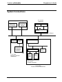
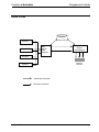
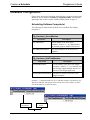
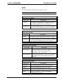
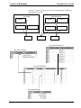
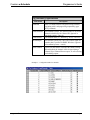
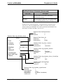
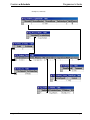
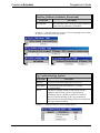
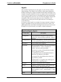
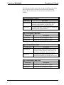
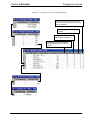
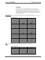
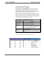
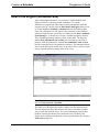
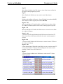
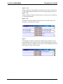
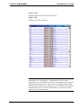
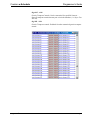
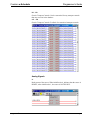
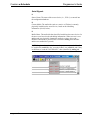
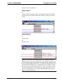
Crestron e-Schedule Programmer’s Guide Programmer's Guide Crestron e-Schedule Crestron Electronics, Inc. Crestron e-Schedule Programmer’s Guide Contents System Overview 1 Product Description.......................................................................................................1 General Information and Terminology .............................................................1 System Components and CNX Gateway Licensing ........................................3 Minimum System Requirements ...................................................................................5 System Connections .....................................................................................................6 Data Flow ......................................................................................................................7 Configuring the e-Schedule Database 8 Database Categories ....................................................................................................8 Database Configuration ................................................................................................9 Scheduling Software Computer(s)...................................................................9 Areas..............................................................................................................10 Head End and Source Devices......................................................................12 Destination Devices .......................................................................................17 Signals ...........................................................................................................19 Signal Macros ................................................................................................21 Signal Macros ................................................................................................22 Privileges........................................................................................................23 Join Number Pass-Throughs .........................................................................24 Real-Time Engine (Scheduler.exe).............................................................................25 Diagnostic Utilities.......................................................................................................29 Watch Signals ................................................................................................29 Configuration..................................................................................................30 e-Schedule Interface to Control Systems 32 SIMPL Windows Programming ...................................................................................32 ActiveCNX Interface Definitions..................................................................................37 Destination (Classroom) ActiveCNX Interface...............................................37 Source ActiveCNX Interface ..........................................................................45 Software License Agreement ..................................................................................... 49 Return and Warranty Policies .................................................................................... 51 Merchandise Returns / Repair Service .......................................................................51 CRESTRON Limited Warranty....................................................................................51 Programmer’s Guide e-Schedule – DOC. 5919 • i Crestron e-Schedule Programmer’s Guide System Overview Product Description Crestron e-Schedule is a Web-based software package for event scheduling and real-time control of media resources across multiple rooms. It replaces Crestron SchoolNet with a much more flexible and robust system, and includes the following features: • Event scheduling and conflict checking of media resources, rooms and source devices. • Real-time signal routing and control of scheduled events. • Copying and re-scheduling of one or all of a day's events. • Scheduling of automatic transport functions such as Source Select, Play and Rewind. • Support for broadband and/or baseband switching (as long as there is full crosspoint capability). • Multiple-room scheduling and grouping and multiple head ends. • Global signals. • Join number pass-throughs for direct communication between a Web browser and a room. • Customizable television channel lists. General Information and Terminology An e-Schedule system usually consists of at least one head end, one or more destinations, and the scheduling software computer(s), all networked through Ethernet. The head end is a central area that contains all the system’s A/V source devices, such as VCRs, laser discs and television tuners. These sources must be controlled by a Crestron control system that supports Ethernet communication, such as the CNMSX or CNRACKX. The devices can be modulated onto broadband video network or switched baseband with any switcher controllable by Crestron. Programmer’s Guide e-Schedule – DOC. 5919 • 1 Crestron e-Schedule Programmer’s Guide The largest destination defined by e-Schedule is a location (i.e., Law School or Business School), a broad area that usually denotes an entire building or a large section of a building. A location is divided into sublocations, which are simply rooms. Various rooms from the same or different locations can be organized into groups. Rooms can also be assigned to one or more groups, (i.e., All First Year Classes or All 8:00 a.m.Classes). As with the head end, a room must be controlled by a Crestron control system that supports Ethernet communication such as the CNMSX, or more typically the CEN-TVAV. Crestron supports room processing for the CNTVAV as well, using an Ethernet-enabled control system as a “bridge” (see section titled e-Schedule Interface to Control Systems). Room controllers are referred to as set-top boxes. Most systems include local room control of head end sources via Crestron touchpanels and/or real-time Web browser pages. End users usually control television settings such as volume, changing channels and turning power on and off, although e-Schedule supports automatic control of these settings as well. The Crestron CNIRHT-MM (445 KHz) transmitter can also be used for real-time control of sources and TV. Events The e-Schedule interface consists of various Web pages that the user navigates in order to schedule events, which are divided into two types: media events and global events. To schedule a media event, the user requests up to six media titles, as well as start and end times and room destinations. In addition, actions called signals that occur automatically can be scheduled at the beginning and/or end of an event. For example, start signals might include dimming the lights and lowering a video screen, while end signals might rewind a VCR tape and raise the blinds. After the scheduling software validates the request, it reserves the sources and media titles for use during the scheduled time. The user who schedules an event can then control it locally or from a Web browser while the event is in progress. They can also edit or delete the event using the Web-based interface. When scheduling a media event for a group, the first room that the user selects will be designated as the “controlling room” that sends transport commands to the head end sources. Only the controlling room can communicate with the head end, and any action that is initiated in the controlling room will also take place in the other “eavesdropping” rooms that make up the group. Global events differ from media events in that they don’t involve any source devices, user-specified locations, or end times. Some common examples of global events are turning lights on or off in a location, activating an alarm system, or adjusting the setting on a thermostat. Global events can be scheduled to coincide with media events or they can occur independently. Programmer’s Guide e-Schedule – DOC. 5919 • 2 Crestron e-Schedule Programmer’s Guide NOTE: Crestron runs a demonstration e-Schedule program at http://www.escheduler.crestron-econtrol.com. To gain access, type “guest” as both the User ID and password. Tiered Switching e-Schedule does not currently support tiered switching, i.e., any environment that does not offer full crosspoint capability. For the e-Schedule system to function properly it must be able to switch any source to any destination without interfering with the routes of other sources or destinations or requiring allocation of a limited number of intermediate channels. System Components and CNX Gateway Licensing The e-Schedule software package consists of the following: • Active Server Pages—Web server application for scheduling and conflict checking. • Real-Time Engine—application for controlling media resources and signal routing between control systems, source devices and destination devices. • e-Schedule Database Directory—divided into four categories: 1) Configuration 2) Web Browser 3) Resource and 4) System. • Documents/Examples Directory—various SIMPL Windows and VT Pro-e programs that define an extensive sample system. Together with the completed configuration databases (also included), the programs can be used as models for most projects. In addition, the system requires a CNX Gateway (the software gateway, not the CNXENET+ card gateway) to enable Ethernet communication with Crestron equipment. The number of connection licenses depends on the configuration of the system. Crestron recommends two possible software configurations. The first is to have all the software and the CNX Gateway on a single computer. In this case, the number of connection licenses will be equal to the total number of IP addresses (meaning all browsers and any hardware with unique IP addresses), plus two. The two extra licenses enable communication between the Web Server and Real-Time Engine applications. For example, in the following system: • One CNMSX-Pro controlling various sources • Five CEN-TVAVs • Five Web browsers A total of thirteen licenses would be required. The second possible configuration is to have two computers, one for the Web Server and the other for the Real-Time Engine, each with its own CNX Gateway. (The Database Directory should be installed on the Web Server for efficiency.) The Web Server computer would then require licenses for all Programmer’s Guide e-Schedule – DOC. 5919 • 3 Crestron e-Schedule Programmer’s Guide browser connections, plus two, and the Real-Time Engine would require licenses for all hardware devices with unique IP addresses, plus two. Thus in the example just described, the Web Server would require seven licenses and the Real-Time Engine computer would require eight licenses. The CNX Gateway runs as a service, not an application, meaning that it starts when the computer boots up, and stops when the computer shuts down. After installation, the Crestron swirl icon will appear in the system tray of the Windows status bar. Right-click the system tray icon to check the current version, add licensing, or simply see the connections that the CNX Gateway is servicing. NOTE: Crestron recommends that all e-Schedule components reside on a separate segment or subnet of the Ethernet network, in order to help ensure that packets will be routed efficiently and quickly. Leading Specifications Maximum number of sources that can be scheduled to one event at one time Maximum number of browsers that can be running simultaneously Maximum number of IP IDs (Crestron control systems, source devices, switcher (if any) and browsers) Maximum number of Cresnet (Crestron Network) devices—i.e., LC1000, CN-TVAV, CT-1550—per CNMSX control system Control system UPZ file SIMPL Windows version Programmer’s Guide 6 90 250 30, if using only CN-TVAVs with no touchpanels or 50, with no more than 25 CNTVAVs if touchpanels are used 5.12.04x (CNMSX) or later 5.12.04w (CN-RACKX) or later 5.12.05v (CEN-TVAV) or later 1.40 (1.50.06 if using CN-TVAV) e-Schedule – DOC. 5919 • 4 Crestron e-Schedule Programmer’s Guide Minimum System Requirements NOTE: If both the Web Server and Real-Time Engine are to be located on one computer, the memory requirements are the same as those listed below for the Web Server PC (no additional memory is required for a one-computer configuration). Web Server PC Hardware Operating System/ Software Crestron Software/Files 600 MHz Pentium II Processor 512 MB RAM Network Card TCP/IP Windows NT Server 4.0 with Service Pack 4 or later Windows NT 4.0 Option Pack (Internet Information Server 4.0 included) Internet Explorer 5 Microsoft Access 2000 Firewall (optional, but recommended) Crestron e-Control CNX Gateway 2.8.6.0 or later Active Server Pages Database Directory Real-Time Engine PC Hardware Operating System Crestron Software 600 MHz Pentium II Processor 128 MB RAM Network Card TCP/IP and UDP/IP Windows 95, 98, or NT Crestron e-Control CNX Gateway 2.8.6.0 or later Real-Time Engine (Scheduler.exe) Browser Computers Hardware Microsoft Software 166 MHz Pentium Processor Windows 95, 98, or NT Internet Explorer 5* *Although any Web browser should work with e-Schedule since Crestron conforms to Java specifications, Netscape Navigator on a PC platform may improperly display objects on top of other objects, and Netscape Navigator on a MacIntosh platform may not display Java objects in the correct position. Programmer’s Guide e-Schedule – DOC. 5919 • 5 Crestron e-Schedule Programmer’s Guide System Connections 0,1 or more Head Ends Real-Time Engine/CNX Gateway Web Server/ CNX Gateway Source1 SourceN CNMSX Ethernet Browser (optional) CENTVAV IR Transmitter/ Touchpanel (optional) 0,1 or more Ethernet-connected destinations CNMSX Misc equip CN-TVAV IR Xmit (opt) Misc equip 0,1 or more Cresnet-connected 0,1 or more Cresnet-connected destinations Programmer’s Guide e-Schedule – DOC. 5919 • 6 Crestron e-Schedule Programmer’s Guide Data Flow Databases Browser Browser Web Server/ CNX Gateway Real-Time Engine/ CNX Gateway Browser Crestron Devices Browser Scheduling information Real time information Programmer’s Guide e-Schedule – DOC. 5919 • 7 Crestron e-Schedule Programmer’s Guide Configuring the e-Schedule Database Database Categories The e-Schedule Database Directory is divided into four categories: 1) Configuration 2) Web Browser 3) Resource and 4) System. The Microsoft Access databases in Scheduler_Configuration.mdb must be completed for each installation. Configuration Databases Scheduler_Configuration.mdb—defines the hardware, group and room setup, and user information. The programmer must configure the tables in this database. Scheduler_Events.mdb—automatically stores event information by system, as well as real-time status of sources and destinations. Resource Databases Scheduler_Media.mdb—media database containing all media resources and media attributes. Web Browser Database (DO NOT MODIFY! This database will be overwritten with each new installation and/or upgrade.) Scheduler_WebGUI.mdb—read-only database for the client-side Web browser. System Database (DO NOT MODIFY! This database will be overwritten with each new installation and/or upgrade.) Scheduler_RealTimeControl.mdb—read-only database for the scheduling software. NOTE: After opening any table in Microsoft Access, select Design View from the View menu for detailed information about each field in the table, including data types and descriptions. Programmer’s Guide e-Schedule – DOC. 5919 • 8 Crestron e-Schedule Programmer’s Guide Database Configuration Except where noted, all of the tables detailed in this section are located in the Microsoft Access database, Scheduler_Configuration.mdb. The examples appearing in this section correlate with the Sample System on page 31. Scheduling Software Computer(s) The following two tables define the Web Server and Real-Time Engine computer(s). Cfg_Hardware_ServerMachine Field Name Description ServerMachineId The ID number of the Web Server computer—must be “1”, as e-Schedule does not currently support multiple Web Servers. ServerMachineIPAddress The static IP Address of the Web Server computer. Cfg_Hardware_RealTimeMachine Field Name Description RealTimeMachineId The ID number of the Real-Time Engine computer—must be “1”, as e-Schedule does not currently support multiple instances of the Real-Time Engine application. RealTimeMachineIPAddress The static IP Address of the Real-Time Engine computer. Example 1 – Configuration tables for two e-Schedule computers. (Alternatively, the Web Server and Real-Time Engine can be located on the same computer, in which case the IP Addresses would be the same.) WebServer/ CNX Gateway Programmer’s Guide Real-Time Engine e-Schedule – DOC. 5919 • 9 Crestron e-Schedule Programmer’s Guide Areas The following tables define locations, groups and rooms. NOTE: The system must have at least one location, one group and one room. Cfg_Area_Locations Field Name Description LocationId Each location (building) in the e-Schedule system must be assigned a unique identifier, starting with 1 and proceeding sequentially—gaps are permitted. LocationName The name of the location (i.e., Law School), referenced by the Location ID, and displayed in the user interface. Cfg_Area_Groups Field Name Description GroupId Each group must be assigned a unique identifier, starting with 1 and proceeding sequentially—gaps are permitted. GroupName The name of the group (i.e., First Year Classes), referenced by the Group ID, and displayed in the user interface. Cfg_Area_SubLocations Field Name Description SubLocationId Each sublocation (room) must be assigned a unique identifier, starting with 1 and proceeding sequentially—gaps are permitted. SubLocationName The name of the room (i.e., Room 101), referenced by the SubLocation ID, and displayed in the user interface. Cfg_Area_MapTable Field Name Programmer’s Guide Description LocationId The Location ID taken from Cfg_Area_Locations. GroupId The Group ID taken from Cfg_Area_Groups. SubLocationId The SubLocation ID taken from Cfg_Area_Sublocations. Enable Check box to enable or “remove” the mapping configuration in the system. e-Schedule – DOC. 5919 • 10 Crestron e-Schedule Programmer’s Guide Example 2 – Locations, groups and rooms, with corresponding tables mapping the relationships between them. Law School Business School Room 1 Room 4 Room 2 Room 3 Group 1 Room 5 Room 6 Group 2 Room 7 Group 3 Cfg_Area_SubLocations Cfg_Area_Locations Cfg_Area_MapTable Cfg_Area_Groups Programmer’s Guide e-Schedule – DOC. 5919 • 11 Crestron e-Schedule Programmer’s Guide Head End and Source Devices The following tables define the attributes of all the head end hardware, as well as format types and television settings. Cfg_Hardware_Switcher Field Name Description SwitcherId If a switcher is used (multiple switchers are not permitted), it must be assigned “1” as its unique identifier. SwitcherName The name of the switcher (i.e., AutoPatch)— reserved for future use. RealTimeMachineID Taken from Cfg_Hardware_RealTimeMachine, this ID number must be “1”. IPAddress The static IPAddress of the control system for the switcher. IPID The decimal equivalent of the hexadecimal Cresnet IP ID of the switcher. Enable Check box to enable or “remove” the device in the system. Cfg_Source_FormatType Field Name Programmer’s Guide Description FormatTypeId Each format type must be assigned a unique identifier, starting with 1 and proceeding sequentially—gaps are permitted. Format The format of the source device (i.e., VHS or DVD) displayed in the user interface when media is selected. All media titles must have a corresponding format if they are to be used in a source. Controllable Check box that indicates whether a source device must be controlled, either manually or remotely (i.e., a VCR is controllable, whereas a television tuner is not.) Load Required Check box that indicates if the device requires that a media title be physically loaded into it. (For example, a VCR or CD player requires manual loading, whereas the television tuner does not). e-Schedule – DOC. 5919 • 12 Crestron e-Schedule Programmer’s Guide Cfg_Hardware_LegalChannels Field Name Description ChannelId Each TV channel must be assigned a unique identifer, beginning with 1 and progressing sequentially (gaps NOT permitted). ChannelNumber In broadband systems, the channel number is the actual channel referenced by the Channel ID. (Ignored in baseband systems—enter 0.) ChannelName The channel name (i.e., Bloomberg, History Channel). SwitcherInput In baseband systems only, this is the switcher input ID number that is specified in SIMPL Windows. (Ignored in broadband systems—enter 0.) Valid Channel Check box that enables or disables the channel setting. When disabled, the channel will be skipped during a Channel Up or Channel Down request, as well as during a scheduling request. Example 3 – Configuration table for channels Programmer’s Guide e-Schedule – DOC. 5919 • 13 Crestron e-Schedule Programmer’s Guide Cfg_Hardware_Source Field Name Programmer’s Guide Description SrcID Each source device must be assigned a unique identifier, starting with 1 and proceeding sequentially—gaps are permitted. SrcName The name of the device (i.e., TV Tuner), referenced by the Source ID and displayed in the user interface. LocationID The location of the source device. This ID number is taken from the table Cfg_Area_Locations. RealTimeMachineID Taken from Cfg_Hardware_RealTimeMachine, this ID number must be “1”. IPAddress The static IP Address of the control system for this device. IPID The decimal equivalent of the Cresnet IP ID of the device. SwitcherID For baseband systems, this is the switcher used by the device. This ID number is taken from the table Cfg_Hardware_Switcher. (Ignored in broadband systems.) FormatTypeId The ID number taken from Cfg_Hardware_Source_FormatType. BasicWebPage This ID number must be taken from the BasicPageID field of the table RealTimePages, located in the read-only database, Scheduler_RealTimeControl. (Currently the choices are: 1 = VCR; 2 = DVD; 3 = Projector; 4 = Environment; and 5 = TV Tuner.) Channel In broadband systems only, this ID number must be the same as the ChannelId taken from the table Cfg_Hardware_LegalChannels. (Ignored in baseband systems.) Enable Check box to enable or “remove” the device in the system. e-Schedule – DOC. 5919 • 14 Crestron e-Schedule Programmer’s Guide RealTimeSrcStatus (Scheduler_Events.mdb) Field Name Description SrcId The ID number of the source, taken from Cfg_Hardware_Source. SrcStatus This field must be initialized to the default setting of “0”, indicating that the source is “Ready”. Example 4 (below and following page) – Configuration table for head end VCR source device, with corresponding entries in tables for real-time status, location, switcher, format type and channels. The control system that controls both the VCR and switcher is located at IP Address 192.168.2.173. Database Table: RealTimeSrcStatus SrcId 3 SrcStatus 0 Database Table: Cfg_Hardware_Source Database Table: Status_Src SrcStatusId 3 SrcStatusDesc Ready VCR1 SrcId SrcName LocationId 3 VCR-1 1 IPAddress IPID SwitcherID 192.168.2.173 6 1 FormatTypeId Basic Web Page Channel 1 1 1 Database Table: Cfg_Area_ Locations LocationId 1 LocationName Law School Database Table: Cfg_Hardware_Switcher SwitcherId 1 SwitcherName AutoPatch IPAddress 192.168.2.173 IPID 8 Database Table: Cfg_Hardware_Source_FormatType FormatTypeId 1 Format VHS Database Table: RealTimePages BasicPageId 1 Comment VCR Database Table: Cfg_Hardware_LegalChannels ChannelId 1 ChannelNumber 11 ChannelName VCR-1 SwitcherInput 0 (ignored in broadband) ValidChannel Yes Programmer’s Guide e-Schedule – DOC. 5919 • 15 Crestron e-Schedule Programmer’s Guide Example 4 (continued) Programmer’s Guide e-Schedule – DOC. 5919 • 16 Crestron e-Schedule Programmer’s Guide Cfg_System_Variables Field Name Description GlobalSafeChannel The default television channel for the entire e-Schedule system, both at startup and at the end of a scheduled event, taken from the ChannelId field of Cfg_Hardware_LegalChannels. BasebandOrBroadband 0 = Baseband; 1 = Broadband. Destination Devices Cfg_Hardware_SetTopBox Field Name Programmer’s Guide Description SetTopBoxId The ID number of the set-top box (room controller)—must be the same as the SubLocationId. SubLocationId The ID number of the room where the set-top box is located, taken from Cfg_Area_SubLocations. RealTimeMachineID Taken from Cfg_Hardware_RealTimeMachine, this ID number must be “1”. IPAddress The static IPAddress of the set-top box or control system, if set-top box does not have its own IP Address. IPID The decimal equivalent of the hexadecimal Cresnet IP ID of the set-top box. SetTopBoxType Type of controller, i.e., CEN-TVAV, taken from Cfg_Hardware_SetTopBox_Variables. SwitcherID In baseband systems only, this is the ID number of the head end switcher, taken from Cfg_Hardware_Switcher. SwitcherOutput In baseband systems only, this is the switcher output ID number that is specified in SIMPL Windows. SafeChannel Overrides the global (default) safe channel defined in Cfg_System_Variables (–1 = Use Global Safe Channel)—currently unused. Enable Check box to enable or “remove” the device in the system. e-Schedule – DOC. 5919 • 17 Crestron e-Schedule Programmer’s Guide RealTime_DstStatus (Scheduler_Events.mdb) Field Name SetTopBoxId Description The ID number of the set-top box (room controller), taken from Cfg_Hardware_SetTopBox. Example 5 – Configuration table for set-top box, with corresponding entries in tables for real-time status, sublocation and switcher. Cfg_ConflictChecking_Options Field Name Description OptionId ID for the conflict-checking option (see below). OptionName 1 = RecurringEvents (not available); 2 = Groups; 3 = Multilocation. Active Check box to enable or disable each option. Option 2 should be enabled if the system is to permit group scheduling. Option 3 should be enabled if a “location” denotes a separate building. In this way media that is physically located in one building will not be scheduled for viewing in another building. Example 6 – Configuration table for conflict checking options Programmer’s Guide e-Schedule – DOC. 5919 • 18 Crestron e-Schedule Programmer’s Guide Signals Since the Real-Time Engine routes all signals, it is the reference point for input and output. Thus signals can be defined as either input commands to the Real-Time Engine or output commands from the Real-Time Engine. One example of an input command is an auto-start signal, which is an action such as Rewind or Play that the end-user can schedule to take place automatically at the beginning and/or end of an event. The Real-Time Engine interprets the command as if the rewind or play button on a piece of hardware were actually pressed. It then processes the signal and routes it accordingly to execute the action. In contrast, a global signal is an example of an output command, which can trigger a join number on any device and is not processed as a request. The global signal initiates in the Real-Time Engine itself, and can be used to turn the lights on in a given location, for example, or adjust a thermostat. Cfg_EventSignals_Signals Field Name Description EventSignalId Every signal must be assigned a unique identifier, starting with 1 and proceeding sequentially—gaps are permitted. EventSignalName The name of the signal (i.e., Rewind), referenced by the event signal ID and displayed in the user interface. JoinNumber The join number that is triggered. HardwareId This field, together with the CNXType field, identifies the hardware device—source, set-top box or switcher—that acts on the join number. If the device is a source, its SourceId must be taken from Cfg_Hardware_Source. For a destination device, the SetTopBoxId must be taken from Cfg_Hardware_SetTopBox. For a switcher, the SwitcherId must be taken from Cfg_Hardware_Switcher. (A HardwareId of “0” together with a CNXType of “2” identifies the controlling room.) Programmer’s Guide CNXType 1=Source; 2=Destination; and 4=Switcher. IOType 1=Digital; 2=Analog; 4=Serial—taken from IOType table in Scheduler_RealTimeControl.mdb. IO Specifies whether the signal is an input command or output command. 0 (zero) = output (global), 1 = input (auto-start). Enable Check box to enable or “remove” signal from system. e-Schedule – DOC. 5919 • 19 Crestron e-Schedule Programmer’s Guide The following four tables can be used to change the labelling of the folders that are displayed in the e-Schedule user interface during scheduling requests. The two main folders, Event Start and Event End, cannot be modified. Cfg_EventSignals_Folders Field Name Description FolderNameId Each folder that displays auto-start signals must be assigned a unique identifier, starting with 1 and proceeding sequentially—gaps are permitted. FolderName The name of the folder, referenced by the FolderNameId and displayed in the user interface. Cfg_EventSignals_MapTable Field Name Description FolderNameId Taken from Cfg_EventSignals_Folders. EventSignalId Taken from Cfg_EventSignals_Signals. Cfg_GlobalEvents_Folders Field Name Description FolderNameId Each folder that displays global signals must be assigned a unique identifier, starting with 1 and proceeding sequentially—gaps are permitted. FolderName The name of the folder referenced by the FolderNameId and displayed in the user interface. Cfg_GlobalEvents_MapTable Field Name Programmer’s Guide Description FolderNameId Taken from Cfg_GlobalEvents_Folders. EventSignalId Taken from Cfg_EventSignals_Signals. e-Schedule – DOC. 5919 • 20 Crestron e-Schedule Programmer’s Guide Example 7 – Configuration of auto-start and global signals IO: 0=Output from the Real-Time Engine, 1=Real-Time Engine will receive this signal from the hardware. IOType: 1=Digital, 2=Analog, 3=Serial CNXType: 0=None, 1=Source, 2=SetTopBox, 4=HeadEnd HardwareId: SourceId, SwitcherId or SetTopBoxId that will act on the join number. Programmer’s Guide e-Schedule – DOC. 5919 • 21 Crestron e-Schedule Programmer’s Guide Signal Macros Signal Macros are now implemented in e-Schedule v3.02. Signal Macros combine groups of individual signals and eliminate the need for the user to select each signal separately. Signal Macros can be be used at the beginning and/or end of a Media Event and in Global Signal Events. For example, at the beginning of an media event, a user can select a signal, Auto Start, which will automatically execute the signals, TV Power On, Select Source A, and Play. To insert a signal macro, insert a new signal into the table, Cfg_EventSignals_Signals. The EventSignalID must be >= 1000. Then in the table, Cfg_EventSignals_MacroMapTable, define the signals that this macro will trigger. The field, Order, specifies the sequence order in which each signal will be triggered within the event. For example, the macro, Auto Start, will trigger signals 250, 300, and 301 (TV Power On, Select Source A, and Play). Cfg_EventSignals_Signals EventSignalID 250 251 300 301 302 1000 1001 EventSignalName TV Power On TV Power Off Select Source A Play Stop Auto Start Auto Stop Cfg_EventSignals_MacroMapTable MacroID 1000 1000 1000 1001 1001 1001 Programmer’s Guide SignalID 250 300 301 251 300 302 Join Number … … … … … N/A N/A HardwareID … … … … … N/A N/A Order 1 2 3 1 2 3 e-Schedule – DOC. 5919 • 22 Crestron e-Schedule Programmer’s Guide Privileges User privileges have been greatly improved in version 3.02 and later. Following are the recommended default privileges for both an administrator level account and a user level account. The order of the field values is extremely important since this table is very closely tied to the front end web pages. Please make sure the order here and in e-Schedule matches exactly when editing this table: Administrator (The recommended default values below assume that the administrator’s user ID is 1.) Cfg_User_MapTable UserId 1 1 1 1 1 1 1 1 1 1 1 1 1 1 1 1 1 1 1 1 1 1 1 1 1 1 PrivilegeId 1 3 9 10 4 108 5 110 8 124 101 103 104 106 111 112 113 114 115 116 117 118 119 120 121 122 _Key NONE NONE NONE NONE NONE NONE NONE NONE NONE NONE NONE NONE NONE NONE NONE NONE NONE NONE NONE NONE NONE NONE NONE NONE NONE NONE User (The recommended default values below assume that the user’s user ID is 2.) Cfg_User_MapTable UserId 2 2 2 2 2 2 2 Programmer’s Guide PrivilegeId 1 4 107 5 109 101 102 _Key NONE NONE NONE NONE NONE NONE NONE e-Schedule – DOC. 5919 • 23 Crestron e-Schedule Programmer’s Guide Join Number Pass-Throughs The Cfg_Hardware_JoinNumPassThrus table defines ranges of join numbers that can be used in SIMPL Windows to specify pass-through signals, which are passed back and forth directly between a set-top box (room controller) and Web browser. This is useful for commands such as Volume Up that don’t need to be transmitted to the head end. The Real-Time Engine routes both the input and output signals, as usual. Signals sent from a browser are transmitted to its corresponding set-top box and those sent from a set-top box are transmitted to all connected browsers. A pass-through is only valid between a Web browser and a set-top box (not between a Web browser and switcher, for example). Cfg_Hardware_JoinNumPassThrus Table Field Name Description PassThruStart Start of the range of join numbers. PassThruEnd End of the range of join numbers. Enabled When selected, this check box indicates that the specified join numbers will in fact be programmed as pass-throughs in SIMPL Windows. IOType 1=Digital, 2=Analog. Comment Comment for database—not used by scheduing software. Example 8 – Configuration table for join number pass-throughs Programmer’s Guide e-Schedule – DOC. 5919 • 24 Crestron e-Schedule Programmer’s Guide Real-Time Engine (Scheduler.exe) After configuring the databases, it is necessary to launch the Real-Time Engine in order to set preferences and connections. To start the Scheduler.exe program (the CNX Gateway starts automatically when the computer boots up), double-click the Start Real Time Engine shortcut icon or select Crestron | e-Schedule | Scheduler.exe from the Windows Start menu. The e-Schedule icon will appear in the system tray of the Windows status bar. Right-click the system tray icon and then select Show e-Schedule Event Manager… to display the Crestron e-Schedule application window. The e-Schedule application window consists of two panes. The top pane, marked Next Scheduled Events to End, lists events that are currently in progress, while the bottom pane, marked Next Scheduled Events to Start, lists the events that have been scheduled to start next. The information about each event includes the Event ID, name of the source device, media or signal names, start and end times, and the status of the event. Note: To quit the Scheduler.exe application, right-click the system tray icon and select Stop Crestron e-Schedule. The status bar of the application window displays two date and time areas. The first indicates the latest date and time that a new or modified schedule was received from the Web Server. The second indicates the last time that the Real-Time Engine checked for a scheduled event. (The Real-Time Engine can be configured to check for events at specified intervals, using the Preferences dialog box.) Programmer’s Guide e-Schedule – DOC. 5919 • 25 Crestron e-Schedule Programmer’s Guide Setting Preferences File Paths Select Edit | Preferences to open the Preferences dialog box, which consists of a tabbed page. The File Paths tab displays the path that points to the Crestron e-Schedule Database Directory, containing all the e-Schedule databases. Programmer’s Guide e-Schedule – DOC. 5919 • 26 Crestron e-Schedule Programmer’s Guide Real Time Machine The Real Time Machine tab of the Preferences dialog box is used to specify IP Addresses and other system settings. • Scheduler Gateway IP Address—specifies the IP Address of the CNX Gateway computer for the Real-Time Engine. This IP Address may or may not be the same as that of the Web Server. (See Web Server Gateway IP Address, below.) • Web Server Gateway IP Address—specifies the IP Address of the CNX Gateway computer for the Web Server. • Check for scheduled events every ‘n’ seconds—configures the Real-Time Engine to check for scheduled events at the specified interval. Crestron recommends the default setting. (See NOTE, below.) NOTE: Crestron recommends using the default settings for periodic system checks, as lengthening or shortening the time interval may adversely affect system response. Programmer’s Guide e-Schedule – DOC. 5919 • 27 Crestron e-Schedule Programmer’s Guide Connections The Current Connections area of the Connections tab lists the IP Addresses of all hardware devices that are configured to run with the RealTime Engine. Each field also displays the connection status and CNX Gateway connection handle, for debugging purposes. Check for new connections every ‘n’ seconds—since set-top boxes and browsers are likely to be dynamically connected and disconnected to the system at any time, the Real-Time Engine will continuously poll all hardware at the specified interval, to make sure a connection is active and valid. (See NOTE, below.) NOTE: Crestron recommends using the default settings for periodic system checks, as lengthening or shortening the time interval may adversely affect system response. Programmer’s Guide e-Schedule – DOC. 5919 • 28 Crestron e-Schedule Programmer’s Guide Diagnostic Utilities The Configuration menu of the Real-Time Engine application window includes two options for debugging, Watch Signals and Configuration. Watch Signals The Watch Signals window displays information about all the signals that the Real-Time Engine receives and transmits. As stated previously, all signals are defined as either input to the Scheduler or output from the Scheduler, and this is specified in the I/O field. The IO Type field gives the type of signal—digital, analog or serial. The Value field gives the value that was sent. Command Type lists the type of target location for the command. This should match the Which CNX field that displays the CNX Interface. Handle lists the CNX Gateway connection handle. The Watch Signals window also gives the join number and description of all commands. NOTE: The “Watch Signals” window should only be used for debugging, since the system slows down dramatically when this window is open. Programmer’s Guide e-Schedule – DOC. 5919 • 29 Crestron e-Schedule Programmer’s Guide Configuration The “Configuration Diagnostics” dialog box includes tabs for each component of the e-Schedule system. Configuration diagnostics should be reviewed whenever the e-Schedule databases are created, modified, or updated. Select a device from the display list to view information about the corresponding entries as they appear in the configuration databases. The Status window will list any errors or omissions. NOTE: Whenever a new e-Schedule version is installed or upgraded the Database Update Utility is automotically launched. This will ensure that the database tables are in the correct format. Crestron recommends viewing the Configuration Diagnostics after this utility runs. Configuration Diagnostics dialog boxes Programmer’s Guide e-Schedule – DOC. 5919 • 30 Crestron e-Schedule Programmer’s Guide Programmer’s Guide e-Schedule – DOC. 5919 • 31 Crestron e-Schedule Programmer’s Guide e-Schedule Interface to Control Systems SIMPL Windows Programming The e-Schedule Documents directory contains various programs that define the sample system illustrated in Figure 1. Together with the completed configuration databases (also included), these can be used as programming models. Programming Requirements Firmware/Software Programmer’s Guide Version (Minimum) CNMSX (AV/Pro) 5.12.04x CNRACKX/CNRACKX-DP 5.12.04w CEN-TVAV 5.12.05v SIMPL Windows 1.40.07 (1.50.06 if using CNTVAV) Symbol Library smwlib100.exe e-Schedule – DOC. 5919 • 32 Crestron e-Schedule Programmer’s Guide Figure 1: Sample System e-Schedule PC(s) Real-Time Engine 192.168.1.104 Web Server/ CNX Gateway 192.168.1.105 Ethernet Head End VCR1 IP ID 06 VCR2 IP ID 07 Classroom 2 IR IR CEN-TVAV 192.168.2.171 Classroom Interface IP ID 03 Local Source IP ID 04 IR IR Local VCR Cresnet Local TV Cresnet CNECI-4 ID 7E IR IR Cresnet Cresnet Touchpanel ID 03 CNECI-4 ID 7E RS-232 Switcher IP ID 08 Classroom 1 IR Local TV Touchpanel ID 03 DVD2 IP ID 0B Tuner IP ID 0C CEN-TVAV 192.168.2.172 Classroom Interface IP ID 03 Local Source IP ID 04 Local VCR Cresnet IR Classroom 3 IR IR MSX 192.168.2.173 Classroom 1 Control IP ID 03 Classroom 1 Local Source IP ID 04 DVD1 IP ID 0A Touchpanel ID 03 VCR3 IP ID 09 CN-TVAV ID 50 Slot 5 Ports 1-4 CN-ISC for: Room Control (Port 1) Local Source Control (Port 2) Touch Panel (Port 3) CNECI-4 (Port 4) IR Local VCR Cresnet IR Local TV Touchpanel ID 04 CNECI-4 ID 7E Programmer’s Guide e-Schedule – DOC. 5919 • 33 Crestron e-Schedule Programmer’s Guide Sample System Configuration As illustrated in Figure 1, the sample system consists of two e-Schedule computers and one head end that controls three classrooms. The head end has six video sources on a CNMSX-Pro, although any Ethernet-enabled control system can be used. Classroom 1 is controlled locally by a CN-TVAV; Classrooms 2 and 3 are controlled by CEN-TVAVs. All three classrooms have local room control from both an MRHC transmitter and a touchpanel, and lighting control via a CNECI-4 high voltage relay module. The exact configuration is as follows: • 1 Real-Time Engine and 1 Web Server/CNX Gateway, located at IP Addresses 192.168.1.104 and 192.168.1.105. • 1 head end CNMSX-Pro (“Headend MSX #1”) at IP Address 192.168.2.173. • 3 VCR sources at IP IDs 06, 07 and 09, on Headend MSX #1. • 2 DVD players at IP IDs 0A and 0B, on Headend MSX #1. • 1 television tuner at IP ID 0C, on Headend MSX #1. • 1 switcher at IP ID 08, on Headend MSX # 1. • 1 CN-TVAV (“Classroom 1”), at Cresnet ID 50, which is bridged from Cresnet to Ethernet by Headend MSX #1. • 2 CEN-TVAVs (“Classroom 2” and “Classroom 3”) that are located at IP Addresses 192.168.2.171 and 192.168.2.172. • CNIRHT-MM transmitters, at RF ID EF, to control each CENTVAV. • 2 CNECI-4 modules at Cresnet ID 7E for local lighting of CENTVAV Classrooms 2 and 3. • 1 CNECI-4 at Cresnet ID 7E, for CN-TVAV Classroom 1, controlled by the bridge Headend MSX #1. • 2 touchpanels at Cresnet ID 03 for local control of Classrooms 2 and 3. • 1 touchpanel at Cresnet ID 04 for Classroom 1, controlled by the bridge Headend MSX #1. Note: All entries in the IP Table of each control system must reference the IP Address of the CNX Gateway. ActiveCNX Interface An ActiveCNX Interface module (found in the Ethernet Control Modules folder of the Configuration Manager) enables Ethernet communication between the devices on a control system and the CNX Gateway/e-Schedule Programmer’s Guide e-Schedule – DOC. 5919 • 34 Crestron e-Schedule Programmer’s Guide software. An ActiveCNX Interface is considered an Ethernet "device," and therefore gets an IP ID and an entry in the IP Table, which references the IP Address of the CNX Gateway. The e-Schedule system uses four ActiveCNX Interfaces, each with different definitions for 1) Sources 2) Switchers 3) Destinations and 4) Global Signals. Sources—each source device in the head end must have a corresponding ActiveCNX Interface programmed into the control system. For example, the six source devices in the head end of the sample system require six “Source”ActiveCNX Interfaces to be programmed into the CNMSX-Pro. Switchers—if a switcher is used, it must have a “Switcher” ActiveCNX Interface programmed into the control system. Destinations—each destination (set-top box/room) must have a “Destination” ActiveCNX Interface programmed into the local control system. Each local source, if any, must have a “Source” ActiveCNX Interface programmed into the local control system. For example, Classrooms 2 and 3 of the sample system each have one “Destination” and one “Source” Interface programmed into the CEN-TVAV. Global Signals—each location where global events may be scheduled must have a “Global Signals” ActiveCNX Interface programmed into the appropriate control system. The Cfg_EventSignals_Signals table can then be configured to schedule and activate specified join numbers on this ActiveCNX Interface. Non-Ethernet Cresnet Hardware In the sample program, Classroom 1 is controlled locally by a CN-TVAV—a Cresnet controller with no Ethernet capabilities. Therefore, an Ethernetenabled control system must serve as a bridge from the Cresnet-based hardware to the Ethernet network. In this case the "bridge" is the head end control system, but any Ethernet-enabled control system can be used. There are two ways to enable communication between a CN-TVAV and the Ethernet network. The first is to program all the logic in the bridge control system and pass the signals to the CN-TVAV hardware remotely, with no programming in the CN-TVAV itself. Such a program is difficult to maintain, however, and requires a great deal of repetition. The second, preferred, method involves the following: 1. Program a “Destination” ActiveCNX Interface for the CNTVAV, as well as a “Source” ActiveCNX Interface for each local source, into the bridge control system (in this case the head end CNMSX-Pro). The ActiveCNX controls are given IP IDs and entries in the IP Table that reference the IP Address of the CNX Gateway, as usual. 2. Route the signals from each ActiveCNX Interface to the CNTVAV through an ISC symbol on Slot 5 of the CN-TVAV. In this way the signals can be manipulated locally. Programmer’s Guide e-Schedule – DOC. 5919 • 35 Crestron e-Schedule Programmer’s Guide Since the CN-TVAV in Classroom 1 does not support Cresnet peripherals, the local touchpanel and CNECI-4 must be wired directly to the Cresnet network and bridged to Ethernet by the head end control system. Thus the control signals for this hardware must also be routed through ISC symbols. InterSystem Communications Symbol An ISC, or InterSystem Communications symbol is used to pass digital, analog and serial signals between control systems. An ISC symbol is programmed identically to an ActiveCNX Interface and its definitions are determined by whether it is a 1) Source or 2) Destination. CEN-TVAV The CEN-TVAV units that control Classrooms 2 and 3 of the sample system are loaded with the same program, since they both have the same configuration. Here a “Destination” ActiveCNX Interface and a “Source” ActiveCNX Interface (for the local VCR source) will be programmed into the CEN-TVAV. The touchpanel and CNECI-4 will communicate with the CEN-TVAV through Cresnet, as usual, and the MRHC transmitter will control settings for Power, Mute, Volume, Source Control and View Channel. Points to Remember • All components of an e-Schedule system—the Web Server, Real-Time Engine, CNX Gateway(s), and Crestron control systems—must have static IP addresses. • e-Schedule defines three ActiveCNX Interfaces, each with different signals for 1) Sources 2) Switchers and 3) Destinations. • An ActiveCNX Interface is considered an Ethernet "device," and therefore gets an IP ID and an entry in the IP Table, which must reference the IP Address of the CNX Gateway. • An Ethernet enabled control system must serve as a bridge from any non-Ethernet Cresnet-based hardware to the Ethernet network. The programming is as follows: 1. In the bridge control system, include a “Destination” ActiveCNX Interface for the non-Ethernet controller, and a “Source” Active CNX Interface for each local source (if any). 2. Use InterSystem Communication symbols to pass signals back and forth from the bridge to the nonEthernet hardware. Programmer’s Guide • An ISC is programmed identically to an ActiveCNX Interface. • Avoid tiered switching, i.e., any environment where resource allocation problems may arise. e-Schedule – DOC. 5919 • 36 Crestron e-Schedule Programmer’s Guide ActiveCNX Interface Definitions The definitions that are outlined in this section are contained in the Definitions subfolder of the e-Schedule Documents Directory. They are listed as follows: • Classroom Definitions.smw • Head End Definitions.smw (includes Switcher definitions) Destination (Classroom) ActiveCNX Interface Digital Join Numbers Signals on the left represent data being sent to the Scheduler (input to the Scheduler); signals on the right represent data coming from the Scheduler (output from the Scheduler) . dig o21 – o27 SourceA – SourceF and SourceLocal: The rising edge of the signal indicates to the Scheduler that the specified source device is being requested for use. (The Scheduler then checks the validity of the request.) dig i21 – i27 Feedback for SourceA – SourceF and SourceLocal: If the specified request is valid, the Scheduler provides feedback that latches high for the duration of the event, then clears when the event is over. Note: The switching logic for a local source must be included in the Classroom program. For example, a "Main" feed from the head end might go into one input of a TV, while that of the local source would go on another input of the TV. If any of the SourceA – SourceF feedback signals goes high, the room's control program should then select the "head end" input; if the Local Source feedback signal goes high, the local input should be selected. Programmer’s Guide e-Schedule – DOC. 5919 • 37 Crestron e-Schedule Programmer’s Guide dig o39 Mute: Sends feedback to the Web browser when a Mute button (defined in the room's control program) is pressed. dig i39 Mute: Enables the Web browser to control a room's Mute button. dig o40 Refreshes the feedback of SourceA - SourceF (digital join numbers i21-i27) and Transport Controls (digital join numbers i84-i104). dig o41 – o42 Mute On and Mute Off: Sends feedback to the Web browser when a Mute On or Mute Off button (defined in the room's control program) is pressed. dig i41 – i42 Mute On and Mute Off: Enables the Web browser to control a room's Mute On or Mute Off button. dig o43 – o44 TV Power On /Off: Sends feedback to the Web browser when a local TV Power On or Power Off button (defined in the room's control program) is pressed. dig i43 - i44 TV Power On/Off: Enables the Web browser to control a room's TV Power On or Power Off button. dig o45 – o46 Current Sensor Status: When ON signal is high, sets or re-sets the room's TV to a specified channel. TV Power must be managed in the room's control program. (Feature reserved for future use.) dig o47 TV Power: Sends feedback to the Web browser when a local TV Power button is pressed. Programmer’s Guide e-Schedule – DOC. 5919 • 38 Crestron e-Schedule Programmer’s Guide dig o61 – o62 Volume Up/Down: Sends feedback to the Web browser when a Volume Up or Volume Down button (defined in the room's control program) is pressed. dig i61 – i62 Volume Up/Down: Enables the Web browser to control a room's Volume Up or Volume Down button. dig i63 – i64 TV Channel Up/Down: Enables the Web browser to control a room's TV Channel Up or Channel Down button. dig i74 Controlling Room: When signal is high, indicates that a particular room is the controlling room in a group. This is useful for display purposes (such as putting up a flag on a touchpanel so that a user in a non-controlling room will know that they cannot control settings). Programmer’s Guide e-Schedule – DOC. 5919 • 39 Crestron e-Schedule Programmer’s Guide dig o85 – o104 Transport controls for SourceA-SourceF devices. dig i85 – i104 Feedback of the specified source. NOTE: If a join number that specifies a Pass-Through signal is also used by the Scheduler (i.e., join number 21, which identifies SourceA on the “Destination” ActiveCNX Interface), the Pass-Through takes priority and the original command is ignored. A signal cannot be configured as both a PassThrough and a Global Event. For example, to pass a LIGHTS-ON command from a Web browser to a room and to schedule it as a global event would require two separate join numbers. Programmer’s Guide e-Schedule – DOC. 5919 • 40 Crestron e-Schedule Programmer’s Guide dig o105 – o124 Generic Transport Controls: Can be customized for specified SourceA – SourceF transport controls that may not exist in the database. (i.e. Super Fast Rewind). dig i105 – i124 Generic Transport controls: Feedback from the customized generic transport control. Programmer’s Guide e-Schedule – DOC. 5919 • 41 Crestron e-Schedule Programmer’s Guide dig o219 – o230 Numeric Keypad for doing a View Channel: Sends feedback to the Web browser when View Channel keypad buttons in a room are pressed. dig i219 – i230 Numeric Keypad for doing a View Channel: Enables the Web browser to control the View Channel keypad in a room. dig i500 – i600 Crestron is currently developing support for this range of reserved join numbers (defined in the fixed database, Scheduler_RealTimeControl.mdb.), to be used to indicate the unique page on a Crestron touchpanel that would display the transport controls of a device. For example, if the signal indicates SourceA, then the touchpanel would display a page containing the transport controls for SourceA. The signal can be used to trip logic for a subpage, page flip, etc. Thus far the following join numbers have been reserved and are available for use: dig i501 (Environment); dig i502 (Projector); dig i503 (VCR); dig i504 (DVD); and dig i505 (TV Tuner). Programmer’s Guide e-Schedule – DOC. 5919 • 42 Crestron e-Schedule Programmer’s Guide Analog Signals o3 Indicates to the Scheduler that a particular channel has been requested. i3 Sets the television to the requested channel, if the channel has been checked as a valid channel in the Cfg_Hardware_LegalChannels database table. Serial Signals i6 – i11 Media titles for SourceA - SourceF (i.e., The Matrix). i12 – i17 Device names of SourceA - SourceF (i.e., VCR-5). i18 Group name. i19 Room name. i20 Status of the event—can be Waiting, Ready, In Progress, Done, Cancelled, or Modified. i21 – i26 Status of SourceA – SourceF for an event—can be Ready or Not Ready. i27 TV channel name. Programmer’s Guide e-Schedule – DOC. 5919 • 43 Crestron e-Schedule Programmer’s Guide i28 Time and Date: Reissued every hour in the format HH:MM:SS\x20MN/DD/YYYY (The \x20 between SS and MN indicates a space.) Field Description Format HH Hour 00-23 MM Minutes 00-59 SS Seconds 00-59 MN Month 01-12 DD Day 01-31 YYYY Year 4 digits NOTE: The Classroom programs of the sample system contain a SIMPL+ module to parse the string and set the time and date in the control system. Programmer’s Guide e-Schedule – DOC. 5919 • 44 Crestron e-Schedule Programmer’s Guide Source ActiveCNX Interface Digital Signals i21 – i40 Transport controls: Input from the Scheduler to activate a transport control for the corresponding source (typically tied to logic for the device or to an IR driver). o21 – o40 Transport feedback for the source, routed from the Scheduler to the room that is controlling the source. Programmer’s Guide e-Schedule – DOC. 5919 • 45 Crestron e-Schedule Programmer’s Guide i41 – i60 Generic Transport Controls: Can be customized for any transport controls that may not exist in the database. o41 – o60 Generic Transport Controls: Feedback for customized transport controls. Analog Signals o1 Ready status of the source: When initialized to 0, indicates that the source is READY; when initialized to 1, the source is NOT READY. Programmer’s Guide e-Schedule – DOC. 5919 • 46 Crestron e-Schedule Programmer’s Guide Serial Signals i1 Source Name: The name of the source device (i.e., VCR-1), as entered into the configuration database. i2 Current Media: The media title (such as a movie or CD) that is currently physically loaded into the source device, based on the scheduling information. (See i3, below). i3 Media Name: The media title that should be loaded into the source device for the next event, based on the scheduling information. (When an event is over and the end user physically changes the media in a source device, the READY button must be pressed. This re-initializes analog o1 to READY and the next media title is posted.) NOTE: Logic can be written in the control system to compare the "should be" media title (serial i2) to the "currently loaded" one (serial i3), and if they are different, to send the "NOT READY" value (identified by analog o1). Programmer’s Guide e-Schedule – DOC. 5919 • 47 Crestron e-Schedule Programmer’s Guide Switcher ActiveCNX Interface Digital Signals i1 Switcher TAKE: When high, triggers analog signals i1 and i2 to determine the appropriate serial string to send to the switcher, in order to execute the switch. Analog Signals i1 Switcher input i2 Switcher output NOTE: In certain cases the Scheduler may try to send many switches in rapid succession to this ActiveCNX Interface. This might occur if there were several rooms in a group and one source was selected—the switcher would have to switch the input to each room—or if more than one room were set to the safe channel simultaneously. It is suggested to write a SIMPL+ module that queues the input/output pair each time a TAKE is encountered. Using a loop in the Main() function, the strings that are sent to the switcher can be slowed to a manageable pace. The program HeadEndMSX.smw contains a SIMPL+ module that does this. Programmer’s Guide e-Schedule – DOC. 5919 • 48 Crestron e-Schedule Programmer’s Guide Software License Agreement This License Agreement (“Agreement”) is a legal contract between you (either an individual or a single business entity) and Crestron Electronics, Inc. (“Crestron”) for software referenced in this guide, which includes computer software and, as applicable, associated media, printed materials, and “online” or electronic documentation (the “Software”). BY INSTALLING, COPYING, OR OTHERWISE USING THE SOFTWARE, YOU REPRESENT THAT YOU ARE AN AUTHORIZED DEALER OF CRESTRON PRODUCTS OR A CRESTRON AUTHORIZED INDEPENDENT PROGRAMMER AND YOU AGREE TO BE BOUND BY THE TERMS OF THIS AGREEMENT. IF YOU DO NOT AGREE TO THE TERMS OF THIS AGREEMENT, DO NOT INSTALL OR USE THE SOFTWARE. IF YOU HAVE PAID A FEE FOR THIS LICENSE AND DO NOT ACCEPT THE TERMS OF THIS AGREEMENT, CRESTRON WILL REFUND THE FEE TO YOU PROVIDED YOU (1) CLICK THE DO NOT ACCEPT BUTTON, (2) DO NOT INSTALL THE SOFTWARE AND (3) RETURN ALL SOFTWARE, MEDIA AND OTHER DOCUMENTATION AND MATERIALS PROVIDED WITH THE SOFTWARE TO CRESTRON AT: CRESTRON ELECTRONICS, INC., 15 VOLVO DRIVE, ROCKLEIGH, NEW JERSEY 07647, WITHIN 30 DAYS OF PAYMENT. LICENSE TERMS Crestron hereby grants You and You accept a nonexclusive, nontransferable license to use the Software (a) in machine readable object code together with the related explanatory written materials provided by Creston (b) on a central processing unit (“CPU”) owned or leased or otherwise controlled exclusively by You, and (c) only as authorized in this Agreement and the related explanatory files and written materials provided by Crestron. If this software requires payment for a license, you may make one backup copy of the Software, provided Your backup copy is not installed or used on any CPU. You may not transfer the rights of this Agreement to a backup copy unless the installed copy of the Software is destroyed or otherwise inoperable and You transfer all rights in the Software. You may not transfer the license granted pursuant to this Agreement or assign this Agreement without the express written consent of Crestron. If this software requires payment for a license, the total number of CPU’s on which all versions of the Software are installed may not exceed one per license fee (1) and no concurrent, server or network use of the Software (including any permitted back-up copies) is permitted, including but not limited to using the Software (a) either directly or through commands, data or instructions from or to another computer (b) for local, campus or wide area network, internet or web hosting services; or (c) pursuant to any rental, sharing or “service bureau” arrangement. The Software is designed as a software development and customization tool. As such Crestron cannot and does not guarantee any results of use of the Software or that the Software will operate error free and You acknowledge that any development that You perform using the Software or Host Application is done entirely at Your own risk. The Software is licensed and not sold. Crestron retains ownership of the Software and all copies of the Software and reserves all rights not expressly granted in writing. OTHER LIMITATIONS You must be an Authorized Dealer of Crestron products or a Crestron Authorized Independent Programmer to install or use the Software. If Your status as a Crestron Authorized Dealer or Crestron Authorized Independent Programmer is terminated, Your license is also terminated. You may not rent, lease, lend, sublicense, distribute or otherwise transfer or assign any interest in or to the Software. You may not reverse engineer, decompile, or disassemble the Software. You agree that the Software will not be shipped, transferred or exported into any country or used in any manner prohibited by the United States Export Administration Act or any other export laws, restrictions or regulations (“Export Laws”). By downloading or installing the Software You (a) are certifying that You are not a national of Cuba, Iran, Iraq, Libya, North Korea, Sudan, or Syria or any country to which the United States embargoes goods (b) are certifying that You are not otherwise prohibited from receiving the Software and (c) You agree to comply with the Export Laws. If any part of this Agreement is found void and unenforceable, it will not affect the validity of the balance of the Agreement, which shall remain valid and enforceable according to its terms. This Agreement may only be modified by a writing signed by an authorized officer of Crestron. Updates may be licensed to You by Crestron with additional or different terms. This is the entire agreement between Crestron and You relating to the Software and it supersedes any prior representations, discussions, undertakings, communications or advertising relating to the Software. The failure of either party to enforce any right or take any action in the event of a breach hereunder shall constitute a waiver unless expressly acknowledged and set forth in writing by the party alleged to have provided such waiver. Programmer’s Guide e-Schedule – DOC. 5919 • 49 Crestron e-Schedule Programmer’s Guide If You are a business or organization, You agree that upon request from Crestron or its authorized agent, You will within thirty (30) days fully document and certify that use of any and all Software at the time of the request is in conformity with Your valid licenses from Crestron of its authorized agent. Without prejudice to any other rights, Crestron may terminate this Agreement immediately upon notice if you fail to comply with the terms and conditions of this Agreement. In such event, you must destroy all copies of the Software and all of its component parts. PROPRIETARY RIGHTS Copyright. All title and copyrights in and to the Software (including, without limitation, any images, photographs, animations, video, audio, music, text, and “applets” incorporated into the Software), the accompanying media and printed materials, and any copies of the Software are owned by Crestron or its suppliers. The Software is protected by copyright laws and international treaty provisions. Therefore, you must treat the Software like any other copyrighted material, subject to the provisions of this Agreement. Submissions. Should you decide to transmit to Crestron’s website by any means or by any media any materials or other information (including, without limitation, ideas, concepts or techniques for new or improved services and products), whether as information, feedback, data, questions, comments, suggestions or the like, you agree such submissions are unrestricted and shall be deemed non-confidential and you automatically grant Crestron and its assigns a non-exclusive, royalty-tree, worldwide, perpetual, irrevocable license, with the right to sublicense, to use, copy, transmit, distribute, create derivative works of, display and perform the same. Trademarks. CRESTRON and the Swirl Logo are registered trademarks of Crestron Electronics, Inc. You shall not remove or conceal any trademark or proprietary notice of Crestron from the Software including any back-up copy. GOVERNING LAW This Agreement shall be governed by the laws of the State of New Jersey, without regard to conflicts of laws principles. Any disputes between the parties to the Agreement shall be brought in the state courts in Bergen County, New Jersey or the federal courts located in the District of New Jersey. The United Nations Convention on Contracts for the International Sale of Goods, shall not apply to this Agreement. CRESTRON LIMITED WARRANTY CRESTRON warrants that: (a) the Software will perform substantially in accordance with the published specifications for a period of ninety (90) days from the date of receipt, and (b) that any hardware accompanying the Software will be subject to its own limited warranty as stated in its accompanying written material. Crestron shall, at its option, repair or replace or refund the license fee for any Software found defective by Crestron if notified by you within the warranty period. The foregoing remedy shall be your exclusive remedy for any claim or loss arising from the Software. CRESTRON shall not be liable to honor warranty terms if the product has been used in any application other than that for which it was intended, or if it as been subjected to misuse, accidental damage, modification, or improper installation procedures. Furthermore, this warranty does not cover any product that has had the serial number or license code altered, defaced, improperly obtained, or removed. Notwithstanding any agreement to maintain or correct errors or defects Crestron, shall have no obligation to service or correct any error or defect that is not reproducible by Crestron or is deemed in Crestron’s reasonable discretion to have resulted from (1) accident; unusual stress; neglect; misuse; failure of electric power, operation of the Software with other media not meeting or not maintained in accordance with the manufacturer’s specifications; or causes other than ordinary use; (2) improper installation by anyone other than Crestron or its authorized agents of the Software that deviates from any operating procedures established by Crestron in the material and files provided to You by Crestron or its authorized agent; (3) use of the Software on unauthorized hardware; or (4) modification of, alteration of, or additions to the Software undertaken by persons other than Crestron or Crestron’s authorized agents. ANY LIABILITY OF CRESTRON FOR A DEFECTIVE COPY OF THE SOFTWARE WILL BE LIMITED EXCLUSIVELY TO REPAIR OR REPLACEMENT OF YOUR COPY OF THE SOFTWARE WITH ANOTHER COPY OR REFUND OF THE INITIAL LICENSE FEE CRESTRON RECEIVED FROM YOU FOR THE DEFECTIVE COPY OF THE PRODUCT. THIS WARRANTY SHALL BE THE SOLE AND EXCLUSIVE REMEDY TO YOU. IN NO EVENT SHALL CRESTRON BE LIABLE FOR INCIDENTAL, CONSEQUENTIAL, SPECIAL OR PUNITIVE DAMAGES OF ANY KIND (PROPERTY OR ECONOMIC DAMAGES INCLUSIVE), EVEN IF A CRESTRON REPRESENTATIVE HAS BEEN ADVISED OF THE POSSIBILITY OF SUCH DAMAGES OR OF ANY CLAIM BY ANY THIRD PARTY. CRESTRON MAKES NO WARRANTIES, EXPRESS OR IMPLIED, AS TO TITLE OR INFRINGEMENT OF THIRD-PARTY RIGHTS, MERCHANTABILITY OR FITNESS FOR ANY PARTICULAR PURPOSE, OR ANY OTHER WARRANTIES, NOR AUTHORIZES ANY OTHER PARTY TO OFFER ANY WARRANTIES, INCLUDING WARRANTIES OF MERCHANTABILITY FOR THIS PRODUCT. THIS WARRANTY STATEMENT SUPERSEDES ALL PREVIOUS WARRANTIES. Programmer’s Guide e-Schedule – DOC. 5919 • 50 Crestron e-Schedule Programmer’s Guide Return and Warranty Policies Merchandise Returns / Repair Service 1. No merchandise may be returned for credit, exchange, or service without prior authorization from CRESTRON. To obtain warranty service for CRESTRON products, contact the factory and request an RMA (Return Merchandise Authorization) number. Enclose a note specifying the nature of the problem, name and phone number of contact person, RMA number, and return address. 2. Products may be returned for credit, exchange, or service with a CRESTRON Return Merchandise Authorization (RMA) number. Authorized returns must be shipped freight prepaid to CRESTRON, Cresskill, N.J., or its authorized subsidiaries, with RMA number clearly marked on the outside of all cartons. Shipments arriving freight collect or without an RMA number shall be subject to refusal. CRESTRON reserves the right in its sole and absolute discretion to charge a 15% restocking fee, plus shipping costs, on any products returned with an RMA. 3. Return freight charges following repair of items under warranty shall be paid by CRESTRON, shipping by standard ground carrier. In the event repairs are found to be non-warranty, return freight costs shall be paid by the purchaser. CRESTRON Limited Warranty CRESTRON ELECTRONICS, Inc. warrants its products to be free from manufacturing defects in materials and workmanship under normal use for a period of three (3) years from the date of purchase from CRESTRON, with the following exceptions: disk drives and any other moving or rotating mechanical parts, pan/tilt heads and power supplies are covered for a period of one (1) year; touchscreen display and overlay components are covered for 90 days; batteries and incandescent lamps are not covered. This warranty extends to products purchased directly from CRESTRON or an authorized CRESTRON dealer. Purchasers should inquire of the dealer regarding the nature and extent of the dealer's warranty, if any. CRESTRON shall not be liable to honor the terms of this warranty if the product has been used in any application other than that for which it was intended, or if it has been subjected to misuse, accidental damage, modification, or improper installation procedures. Furthermore, this warranty does not cover any product that has had the serial number altered, defaced, or removed. This warranty shall be the sole and exclusive remedy to the original purchaser. In no event shall CRESTRON be liable for incidental or consequential damages of any kind (property or economic damages inclusive) arising from the sale or use of this equipment. CRESTRON is not liable for any claim made by a third party or made by the purchaser for a third party. CRESTRON shall, at its option, repair or replace any product found defective, without charge for parts or labor. Repaired or replaced equipment and parts supplied under this warranty shall be covered only by the unexpired portion of the warranty. Except as expressly set forth in this warranty, CRESTRON makes no other warranties, expressed or implied, nor authorizes any other party to offer any other party to offer any warranty, including any implied warranties of merchantability or fitness for a particular purpose. Any implied warranties that may be imposed by law are limited to the terms of this limited warranty. This warranty statement supercedes all previous warranties. Trademark Information All brand names, product names, and trademarks are the sole property of their respective owners. Windows is a registered trademark of Microsoft Corporation. Windows95/98/Me/XP and WindowsNT/2000 are trademarks of Microsoft Corporation Programmer’s Guide e-Schedule – DOC. 5919 • 51