1
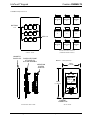
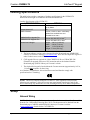
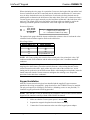
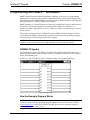
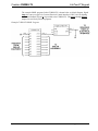
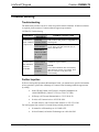
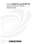
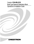
Crestron CNWM-LT9 LiteTouch® Keypad Contents LiteTouch® Keypad: CNWM-LT9 Description Functional Description Physical Description Leading Specifications Setup Network Wiring Keypad Installation Identity Code Programming with SIMPL™ Windows CNWM-LT9 Symbol How the Example Program Works Problem Solving Troubleshooting Further Inquiries Return and Warranty Policies Merchandise Returns / Repair Service CRESTRON Limited Warranty Operations & Installation Guide - DOC. 5785 1 1 1 1 3 3 3 4 5 6 6 6 8 8 8 9 9 9 Contents • i LiteTouch® Keypad Crestron CNWM-LT9 ® LiteTouch Keypad: CNWM-LT9 Description Functional Description The LiteTouch® Keypad, CNWM-LT9, is a 9-button keypad that is part of the Crestron Home™ total control system. It features a faceplate and buttons that match the style and colors of LiteTouch control stations. The CNWM-LT9 is a standard Crestron network (Cresnet) device and may be programmed using SIMPL™ Windows. The CNWM-LT9 is used instead of large banks of switches and/or dimmers and is designed for wall-mounting into a 1-gang electrical box (recommended 2.5” depth). The removable, magnetic faceplate of the keypad can be customized to match a home’s paint colors, wall coverings, or décor. All keypads include custom engraving to label the individual buttons according to their function. Contact Crestron customer support for further instructions and refer to the latest version of the Cresnet Engraving Worksheet for the CNWM-LT9 (Doc. 5859) for engraving directions. The keypad has nine functionally identical buttons and associated light emitting diodes (LEDs) for user feedback indicators. All buttons are momentary switches and provide digital inputs to the Cresnet system. The illumination of the LEDs, which are independently addressable, is programmed by SIMPL Windows. Physical Description Views of the CNWM-LT9 keypad are shown on the next page. Each keypad has nine buttons for system activations and nine LEDs for feedback indicators. The buttons and LEDs are arranged numerically from left to right, top to bottom. The keypad consists of three major assemblies. The faceplate assembly contains a magnetic faceplate and a faceplate frame that is attached to the button assembly. The button assembly consists of a switch assembly with momentary contact closure switches and a printed circuit board. The third assembly is the Crestron system adapter. This supplies Cresnet communications with the keypad buttons and LEDs. At the rear of the keypad is the Cresnet 4-wire, male connector (standard Cresnet network port labeled 24 Y Z G). The supplied female connector provides the Cresnet 24 volts direct current (VDC) operating power and communications to the keypad. Operations & Installation Guide - DOC. 5785 LiteTouch® Keypad: CNWM-LT9 • 1 LiteTouch® Keypad Crestron CNWM-LT9 CNWM-LT9 Physical Views BUTTONS 1-9 LED 1 LED 2 LED 3 BUTTON 1 BUTTON 2 BUTTON 3 LED 4 LED 5 LED 6 BUTTON 4 BUTTON 5 BUTTON 6 LED 7 LED 8 LED 9 BUTTON 7 BUTTON 8 BUTTON 9 LEDs 1-9 LED & BUTTON LAYOUT (VIEWED FROM FRONT) FRONT VIEW MAGNETIC FACEPLATE FACEPLATE FRAME ATTACHED TO BUTTON ASSEMBLY DEPTH = 1.15 in (2.92 cm) 2.83 in (7.19 cm) CRESTRON SYSTEM ADAPTER FCC ID: EROCNWM-LT9 SEE MANUAL CNWM-LT9 4.60 in (11.68 cm) C000000 ZA11217 NET 24 Y Z G CRESNET CONNECTOR EXPANDED SIDE VIEW 2 • LiteTouch® Keypad: CNWM-LT9 REAR VIEW Operations & Installation Guide - DOC. 5785 LiteTouch® Keypad Crestron CNWM-LT9 Leading Specifications The table below provides a summary of leading specifications for the CNWM-LT9. Dimensions and weight are rounded to the nearest hundredth unit. Leading Specifications of the CNWM-LT9 SPECIFICATION Power Requirements Default Network ID SIMPL Windows CNMXS-AV/Pro Upgrade File CNRACKX/-DP Upgrade File Dimensions & Weight DETAILS 24VDC Cresnet power, load factor of six (6) Watts. 4D Version 1.30.01 or later 1 with library update files smwlib62.exe and smwlib62.txt or later.1 Version 50135X.UPZ or later 2 Version 50706W.UPZ or later 2 Height: 4.60 in (11.68 cm) Width: 2.83 in (7.19 cm) Depth: 1.15 in (2.92 cm) 3 Weight: 7.30 oz (0.21 kg) 1 The latest software versions can be obtained from the Downloads page (SIMPLWIN Library) of Crestron’s website (www.crestron.com). New users are required to register in order to obtain access to the FTP site. 2 CNX upgrade files are required for either CNMSX-AV/Pro or CNRACKX/-DP. Filenames for upgrade files have a UPZ extension and can be obtained from the Downloads page (OPSYS Library) of Crestron’s website. 3 The depth of the keypad is listed without the Cresnet connector (approximately 0.45 in, 1.14 cm) plus clearance for the wiring. As of the date of manufacture, this unit has been tested and found to comply with specifications for CE marking: NOTE: This device complies with part 15 of the FCC rules. Operation is subject to the following two conditions: (1) this device may not cause harmful interference, and (2) this device must accept any interference received, including that may cause undesired operation. Setup Network Wiring NOTE: If making category 5 wire connections, refer to the latest revision of the Cresnet Mini Network Cat 5 Interconnect Drawing (Doc. 5819). The document can be obtained from the Downloads page (CABLES and MANUALS Libraries) of Crestron’s website (www.crestron.com). Search for the CAT5.PDF file. Operations & Installation Guide - DOC. 5785 LiteTouch® Keypad: CNWM-LT9 • 3 LiteTouch® Keypad Crestron CNWM-LT9 When calculating the wire gauge for a particular Cresnet run, the length of the run and the load factor of each network unit to be connected must be taken into consideration. If Cresnet units are to be daisy-chained on the run, the load factor of each unit to be daisy-chained must be added together to determine the load factor of the entire chain. If the unit is a home-run from a Crestron system power supply network port, the load factor of that unit is the load factor of the entire run. The length of the run in feet and the load factor of the run should be used in the following resistance equation to calculate the value on the right side of the equation. Resistance Equation R < 40,000 L x LF Where: R = Resistance (refer to next table). L = Length of run (or chain) in feet. LF = Load factor of entire run (or chain). The required wire gauge should be chosen such that the resistance value is less than the value calculated in the resistance equation. Refer to the table below. Wire Gauge Values RESISTANCE (R) WIRE GAUGE 4 6 10 15 13 16 18 20 22 24 (Doubled-CAT 5) NOTE: All Cresnet wiring must consist of two twisted-pairs. One twisted pair is the +24V conductor and the GND conductor and the other twisted pair is the Y conductor and the Z conductor. NOTE: When daisy-chaining Cresnet units, always twist the ends of the incoming wire and outgoing wire which share a pin on the network connector. After twisting the ends, tin the twisted connection with solder. Apply solder only to the ends of the twisted wires. Avoid tinning too far up the wires or the end becomes brittle. After tinning the twisted ends, insert the tinned connection into the Cresnet connector and tighten the retaining screw. Repeat the procedure for the other three conductors. Keypad Installation After the Cresnet network wiring has been installed and the supplied Cresnet connector attached to the wiring in a standard, 1-gang electrical box, the CNWM-LT9 may be installed. The only tool required is a Phillips tip screwdriver. (Mounting screws are not provided.) To install the keypad, perform the following procedure: NOTE: The CNWM-LT9 may be installed in any orientation. This procedure assumes that the keypad will be installed vertically with the LEDs ABOVE the buttons. 1. Make sure that the Cresnet system power is turned OFF. 2. Separate the magnetic faceplate from the button assembly. 3. Connect the Cresnet connector to the rear of the keypad system adapter. 4 • LiteTouch® Keypad: CNWM-LT9 Operations & Installation Guide - DOC. 5785 LiteTouch® Keypad Crestron CNWM-LT9 4. Make sure the LEDs are oriented above the keypad buttons and position the keypad into the electrical box. CAUTION: Excess wire that is pinched between the keypad and electrical box could shortcircuit. Make sure that all excess wire is completely inside the electrical box and not between the box and the keypad. 5. Install the keypad into the electrical box. (Mounting screws are not provided.) 6. Make sure that the LED openings of the magnetic faceplate are aligned with the LEDs and install the faceplate. 7. Turn Cresnet system power ON. Identity Code Every user interface within the Cresnet network requires a unique network identity code (NET ID). These codes are recognized by a two-digit hexadecimal number from 03 to FE. The NET ID of the keypad must match an ID code specified in the SIMPL Windows program. The NET ID of the CNWM-LT9 is factory set to 4D. The NET IDs of multiple keypads must all be unique and changed from a personal computer (PC) via VisionTools™ Pro-e (VT Pro-e) or SIMPL Windows. NOTE: VT Pro-e is a Windows compatible software package for creating Crestron touchpanel screen designs. The method for changing the unit’s NET ID is identical regardless of the software chosen. Attach one of the keypads to the control system (verify that the software is running) and complete the following steps to change the NET ID: 1. Disconnect all Cresnet devices from the control system, except for the keypad that needs to have its NET ID changed. 2. Select Tools | Viewport to open the “Crestron Viewport” dialog box. 3. Select Functions | Set Network ID. The software checks the baud rate and then opens the “Set Network ID” dialog box. 4. In the “Set Network ID” dialog box, highlight the keypad. 5. The NET ID of the keypad appears in the box below the list. Use the scroll arrow to assign another NET ID. 6. When the assigned NET ID appears, select the Set ID button to initiate the change. 7. The software responds with a successful message to confirm the changed NET ID. 8. To verify this procedure, select Diagnostics | Report Network Devices. Confirm that the keypad has a new NET ID code. 9. Reconnect other Cresnet devices that were disconnected in step 1. Operations & Installation Guide - DOC. 5785 LiteTouch® Keypad: CNWM-LT9 • 5 LiteTouch® Keypad Crestron CNWM-LT9 Programming with SIMPL™ Windows SIMPL (Symbol Intensive Master Programming Language) is an easy-to-use programming language that is completely integrated and compatible with all Crestron system hardware. The objects that are used in SIMPL Windows are called symbols. SIMPL Windows offers drag and drop functionality in a familiar Windows environment. SIMPL Windows is Crestron Electronics' software for programming Crestron control systems. It provides a well-designed graphical environment with a number of workspaces (i.e., windows) in which a programmer can select, configure, program, test, and monitor a Crestron control system. The next two sections describe a CNWM-LT9 within a SIMPL Windows program. The first section details the SIMPL symbol and the second section describes how an example program works by using a textual description and a block diagram. NOTE: The following descriptions assume that the reader has knowledge of SIMPL Windows. If not, refer to the extensive help information provided with the software. CNWM-LT9 Symbol The diagram below shows the CNWM-LT9 symbol. The symbol contains nine button press outputs and nine feedback indicator inputs. Refer to “CNWM-LT9 Physical Views” on page 2 for the actual button layout. Detail View of the CNWM-LT9 Symbol in SIMPL Windows’ Programming Manager How the Example Program Works NOTE: There is no need to recreate the example SIMPL Windows program. The program is available from the Software Downloads page (EXAMPLES Library) of Crestron’s website (www.crestron.com). Search for CNWM-LT9.SMW. New users are required to register in order to obtain access to the FTP site. 6 • LiteTouch® Keypad: CNWM-LT9 Operations & Installation Guide - DOC. 5785 Crestron CNWM-LT9 LiteTouch® Keypad The example SIMPL program for the CNWM-LT9 is shown below as a block diagram. Signal lamp 1 is sent to a toggle of a Crestron Electrical Control Interface (CNECI-4A) for lighting control and feedback (signal A) is provided to the CNWM-LT9. The press2 through press9 outputs are used for by similar equipment. Example CNWM-LT9 SIMPL Program Operations & Installation Guide - DOC. 5785 LiteTouch® Keypad: CNWM-LT9 • 7 LiteTouch® Keypad Crestron CNWM-LT9 Problem Solving Troubleshooting The table below provides corrective action for possible trouble situations. If further assistance is required, please contact a Crestron technical support representative. CNWM-LT9 Troubleshooting TROUBLE POSSIBLE C A U S E (S) CORRECTIVE ACTION Keypad does not function when a button is depressed. Keypad is not receiving network power. K e y p a d N E T ID is not unique. K e y p a d N E T ID is not set to m a tch the N E T ID of the SIM P L W indows program . C h e c k w iring and Cresnet connector and confirm that power is supplied to the keypad. From the Viewport (in SIM P L W indows or VT Pro), poll the netw o rk (F4) to verify the NET ID. Keypad functions but L E D indicator does not illu m inate. Feedback signal nam e s incorrect in SIMPL W indows program . Verify S IMPL Windows program for feedback signal nam e s . NOTE: T h e L E D indicators will m o m e n a rily light when a button is pressed. This can be used to verify the LED functionality. Further Inquiries If after reviewing this Operations & Installation Guide, you cannot locate specific information or have questions, please take advantage of Crestron's award winning technical support team by calling: • In the US and Canada, call Crestron’s corporate headquarters at 1-888-CRESTRON [1-888-273-7876] or 1-201-767-3400. • In Europe, call Crestron International at +32-15-50-99-50. • In Asia, call Crestron Asia at +852-2341-2016. • In Latin America, call Crestron Latin America at +525-574-15-90. For local support from exclusive Crestron factory-trained personnel call: • In Australia, call Soundcorp at +613-9488-1555. • In New Zealand, call Amber Technologies at +649-410-8382. 8 • LiteTouch® Keypad: CNWM-LT9 Operations & Installation Guide - DOC. 5785 Crestron CNWM-LT9 LiteTouch® Keypad Return and Warranty Policies Merchandise Returns / Repair Service 1. No merchandise may be returned for credit, exchange, or service without prior authorization from CRESTRON. To obtain warranty service for CRESTRON products, contact the factory and request an RMA (Return Merchandise Authorization) number. Enclose a note specifying the nature of the problem, name and phone number of contact person, RMA number, and return address. 2. Products may be returned for credit, exchange, or service with a CRESTRON Return Merchandise Authorization (RMA) number. Authorized returns must be shipped freight prepaid to CRESTRON, Cresskill, N.J., or its authorized subsidiaries, with RMA number clearly marked on the outside of all cartons. Shipments arriving freight collect or without an RMA number shall be subject to refusal. CRESTRON reserves the right in its sole and absolute discretion to charge a 15% restocking fee, plus shipping costs, on any products returned with an RMA. 3. Return freight charges following repair of items under warranty shall be paid by CRESTRON, shipping by standard ground carrier. In the event repairs are found to be non-warranty, return freight costs shall be paid by the purchaser. CRESTRON Limited Warranty CRESTRON ELECTRONICS, Inc. warrants its Cresnet products, denoted by a "CN" prefix model number, to be free from manufacturing defects in materials and workmanship for a period of three (3) years from the date of shipment to purchaser. Disk drives and any other moving or rotating mechanical parts are covered for a period of one (1) year. CRESTRON warrants all its other products for a period of one year from the defects mentioned above, excluding touchscreen display components which are covered for 90 days. Incandescent lamps are completely excluded from Crestron's Limited Warranty. CRESTRON shall, at its option, repair or replace any product found defective without charge for parts or labor. Repaired or replaced equipment and parts supplied under this warranty shall be covered only by the unexpired portion of the warranty. CRESTRON shall not be liable to honor warranty terms if the product has been used in any application other than that for which it was intended, or if it has been subjected to misuse, accidental damage, modification, or improper installation procedures. Furthermore, this warranty does not cover any product that has had the serial number altered, defaced, or removed. This warranty shall be the sole and exclusive remedy to the purchaser. In no event shall CRESTRON be liable for incidental or consequential damages of any kind (property or economic damages inclusive) arising from the sale or use of this equipment. CRESTRON makes no other warranties nor authorizes any other party to offer any warranty, expressed or implied, including warranties of merchantability for this product. This warranty statement supersedes all previous warranties. Trademark Information All brand names, product names, and trademarks are the sole property of their respective owners. Windows is a registered trademark of Microsoft Corporation. Windows95, Windows98 and WindowsNT are trademarks of Microsoft Corporation. Operations & Installation Guide - DOC. 5785 LiteTouch® Keypad: CNWM-LT9 • 9