1
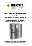
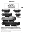
INSTRUCTION MANUAL
No.22
PELLET BOILERS
Type Classic 25, 31, 35, 40, 49, 60 Lambda
with
LAMBDA - HATRONIC from EPROM V 4.2 b
Fuel Extraction systems RAS, RAD, RAPS, GWT
^^
HARGASSNER - HEIZTECHNIK: "Time-tested performance."
A SYSTEM COMBINING THE COMFORT OF OIL HEATING WITH UNMATCHED EFFICIENCY
BA Classic 25L-60L Nr22 0509
Introduction
Preface
Dear customer!
We are glad that you have chosen one of our innovative high quality products and would like to assure you
that you've thereby purchased one of the most reliable heating system available. Please note however that
even for the best product appropriate installation, commissioning and maintenance are required to allow for
best possible performance. The included hydraulic-, connection- and installation schemes will facilitate all of
the above.
Please make sure to follow the maintenance guidelines of the instruction manual to assure a cost-effective
and long life cycle of your heating system. Doing so will help to avoid high repair costs and long down times
by sustaining the system's reliability over many years.
Intended application
The heating system Classic 25-60 is a modern pellet fueled boiler with a nominal output of 25 - 60 kW. The
plant is designed to serve as a central system for supplying hot heating water. The fuel is delivered by one
of our numerous innovative fuel extraction systems.
Provided documents
The following accompanying documents are provided for Classic 25-60 pellet boiler:
- Instruction manual
- Assembly manual (GWTS,RAS,RAPS,RAD)
- Control booklet
- Packing plan
Table of contents
1. INSTALLATION GUIDELINES
Page 2 - 3
2. COMMISSIONING
Page 4
3. MAINTENANCE
Page 5 - 6
4. CONTROL PANEL
Page 7
5. CUSTOMER SETTINGS
Page 8 - 10
6. MANUAL OPERATION
Page 11 - 14
7. COMMISSIONING SETTINGS
Page 15 - 29
8. TROUBLESHOOTING
Page 30 - 35
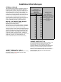
9. COMBUSTION MALFUNCTIONS
Page 36
10. CIRCUIT BOARD AND FUSE PLAN
Page 37
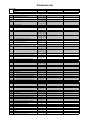
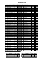
11. PARAMETER LISTS
Page 38 - 40
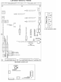
Installation guidelines
1. Electrical installation:
- The electrical installationmust be carried out by a specialist (authorized by the VDE or VOE) and according to the
enclosed plan.
- The power must be supplied by a 230VAC/16A polarity proof connector plug (in accordance with machinery
safety regulations - MSV). Furthermore the main switch must be situated in accordance to the buildung code
and equipped with a pre-fuse having a max. 16A.
Caution :
- Power connectors L and N must be in proper phase. (see connection scheme
- Suction hoses have to be earthed. (see sticker)
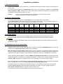
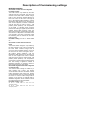
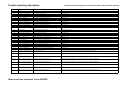
2. Chimney dimensioning :
- The chimney dimensioning is based oncalculations (for flue gas parameters see the table)
- For the initial layout thermally insulated chimneys according to DIN 18160 T1 (thermal resistance group 1) or
appropriate, authorized and moisture resistant flue gas systems must be used
PLANT
TYPE
Output
Flue gas
temp.
CO²
Mass flow
Chimney
draught plant
Max. chimney draught
Firetube
diameter
HARGASSNER
HARGASSNER
HARGASSNER
HARGASSNER
HARGASSNER
HARGASSNER
Classic 25
Classic 31
Classic 35
Classic 40
Classic 49
Classic 60
KW
25,00
31,00
35,00
42,00
49,00
58,00
°C
150
150
150
150
150
150
%
14
14
14
14
14
14
kg / sec
0,0153
0,0189
0,0195
0,0199
0,0247
0,0302
Pa
5
5
5
5
5
5
Pa
10
10
10
10
10
10
m
0,130
0,130
0,150
0,150
0,150
0,150
3. Fire tube design:
The fire tube should be as short as possible, tightly sealed and ascend towards the chimney.
Moreover cleaning lids have to be available and longer tubes should be thermally insulated.
Caution:
A draught controller with blowback flap must be integrated inside the fire tube or chimney (pressure
set point 0,1 mbar).
4. Installation and set up instructions:
- Hargassner HSV boilers meet the standards of class 3 systems according to ÖNORM EN 303-5 as well as the
demands of the 15a BVG agreement. (tested by BLT Wieselburg)
- When the boiler is being installed, safety codes of local fire protection and building inspection departments
must be considered as well as general standards and safety regulations for central heating systems. Moreover a
2
sufficient fresh air supply according to local guidelines (respectively a minimum of 200cm
) has to be provided.
- The fire protection guideline applied in Austria is TRVB H118 supplemental sheet 029. The heating systems are
subsequently tested in accordance to this guideline (test report no. 12679). Due to this high standard, there is no
need for a TMS - temperature monitoring system in the fuel storage room of these heating systems.
- Due to its classification as a "fast shutdown" system (tested by BLT Wieselburg), and in accordance with ÖNORM
B 8131 and DIN 4751, it is not necessaryto install a thermal discharge safety device.
- If the heating system is run without a thermal buffer storage or a long distance heating pump (see hydraulic
scheme) a bypass pump for return temperature augmentation is needed. If a buffer storage is present, a
return mixer or thermal valve (see hydraulic scheme) must be used.
- The hydraulic connection must be installed as shown in the enclosed scheme.
Installation guidelines
5. Safety Guidelines:
The heating system Classic 25-60 is designed and manufactured to meet the latest safety and technology standards.
Improper operation of the heating system caused by deferred maintenance, incorrect use or poor fuel quality could still
lead to personal and material damage.
That is why the heating system Classic 25-60 must only be used for its intended application (see Introduction) and after
safety requirements have been checked.
For safety reasons, the electrical connection must be cut before any kind of maintenance work is started, before
any sort of covering and plating of electrical and rotating parts is removed, and before entering the fuel extraction
area (rotating parts)!
In addition to that, the system must be shut down using the main switch whenever a fatal error occurs during
operation. Make sure to inform a specialist and have the error fixed as soon as possible.
Also mind the fire risk caused by glowing ash when cleaning the boiler.
Caution: Risk of burns ! Internal parts of the boiler could be hot (>50°C)
Do not open the door of the combustion chamber during operation. Only perform cleaning in a cooled down state
of the boiler and note that the ash box might still be hot.
Caution: Risk of injury by rotating parts ! !! Unplug the power supply !
Entering the fuel storage room is strictly forbidden during operation. Assure that the storage room cannot be
entered unauthorized.
Caution: Danger caused by voltage ! !! Unplug the power supply !
Cut the main power supply before removing any covering of electrical parts (fans, drives, etc.).
Caution: Danger caused by flue gas !
Deficient maintenance and cleaning might cause flue gas to leak from the boiler. Shut down the system right
away using the main switch when this happens. Thoroughly aerate the heating room and perform maintenance
and cleaning of the boiler as described in the respective section of the instruction manual or inform the service
department.
Caution: Risk of fire !
Safety codes of local fire protection and building inspection departments must be followed. The fire risk will be
increased by deficient maintenance and cleaning ! (Maintenace and cleaning intervals must be kept, see the
respective section of the instruction manual and the control booklet).
Allow the ash box to cool down before cleaning the boiler.
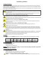
6. Pellets
In accordance with ÖNORM M 7135 pellets are made of compacted saw dust and shavings from untreated
wood.
Heating value
4,8 kWh/kg
Bulk
Water
density content
650 kg/m³
Ash
content
Diameter
Length
Dust
content
Required storage
volume
0,50%
6mm
20-40mm
max.10%
0,9 m³/kW nom.power
ca.7%
Important quality criteria :
- lowest possible dust content
- hard and shiny surface
- untreated wood, free of additives etc.
Caution: Make sure that pellets you buy or receive meet the quality standards as specified
in ÖNORM M 7135 or DIN-Plus.
7. Storage Room Requirements:
-
absence of humidity
minimum dimensions of 2 x 3m (depending on the heat output)
injection and extraction couplings for air injection of pellets
a deflection mat covering the wall that is opposite the injection coupling
The boiler must be shut down while pellets are being loaded (the mode switch is set to "Off".).
Caution:
Inbetriebnahme
As soon as the boiler has been installed appropriately and all safety systems have been
checked, commissioning can be performed using the checklist shown below.
Commissioning:
1.
Test the function of all electrical devices. Further information regarding this step can be
found in chapter: "manual operation"!
2.
With the mode switch set to "Manual", start the automatic pellet delivery by pushing the +
button (display No.7 in case of suction unit (RAS), display No.7a in case of a direct auger
(RAD)). The system will deliver pellets to the intermediate bin until it is switched off by the
level indicator.
3.
Remove the upper heat exchanger lid to gain insight on the grate. Now use the + button
while display no. 4 is shown in Manual operation mode to deliver pellets until they appear on
the grate. When completed, reapply the heat exchanger lid.
4.
With the mode switch either set to "Auto", "HWS" or "Off", you may enter the menu for
commissioning settings by simultaneously pushing the + and - buttons. Adjust the settings
as described in the corresponding chapter "Commissioning settings".
5.
Now turn the mode switch to "Auto" or "HWS". The system will automatically start up and
run according to the chosen mode. Note that the ignition will be delayed for approx. 3 min.
CAUTION:
Commissioning must be performed by a technician with commissioning
certificate. Do not forget to return the completed commissioning
checklist to company Hargassner within 30 days after commissioning.
Note that failing to do so voids all warranty claims!
Maintenance and cleaning
Caution: Safety notice!
For safety reasons, the power supply must be cut before any kind of maintenance work is started, before any
sort of covering and plating of electrical and rotating parts is removed, and before entering the fuel extraction
area (rotating parts)! Mind protection clothing as the boiler or respective parts of the boiler may still be hot!
Your boiler is equipped with automatic systems for ash removal and boiler cleaning. All you have to do is to empty the
ash box at regular intervals. The control display will let you know whenever the ash box is almost full. If you forget to
remove the ash, the boiler will be switched off after a specified time and the message "over-current ash removal motor"
will be displayed. After emptying the ash box, the error can be cleared by pushing "Enter".
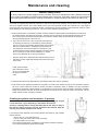
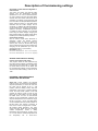
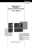
1. Both the boiler and the combustion chamber must be checked for ash deposition (see illustration) at least once
per heating season and cleaned if necessary. Therefore remove both upper heat exchanger lids shown as no.1
and no.2 and clean the heat exchanger and the combustion chamber using the provided brush and poker,
removing all disposed ash, shown as no.3.
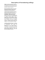
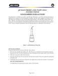
2. If you can not fix the error "over-current ash removal motor"
by emptying the ash box, try the following: remove the ash
box no.11 and unscrew the ash removal motor from the back
side of the boiler (Caution: completely remove screw no.5
from the auger). Unscrew the lower front casing no.7 and
proceed with unscrewing and removing the four screws shown
as no.8. Now pull out the ash removal device no.10 and
remove any disposed ash or other sort of debris.
Attention: When done, refill the small container shown as no.9
with ash to ensure a tight seal between the rear and front part
of the boiler.
Lastly, clean the lower
part of the boiler, shown
as no.4, and reassemble
the parts in reversed
order.
3. Check the fire tube for ash disposal twice per heating season and clean if necessary.
4. Even under normal operating conditions the formation of cracks in the fireclay concrete of the combustion chamber
will occur. These cracks are caused by tension and lead to expansion joints. In addition, the high combustion
temperature sometimes causes particles to be detached from the surface of the secondary combustion chamber.
Please note however, that both of these processes are normal and do not affect the function of the boiler. For this
reason neither of them is subject to warranty.
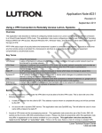
Cleaning the pellets suction turbine: (if present)
Remove the suction turbine no.8 and clean out any dust clogging the grid
no.9 at least once a year, depending on the pellets' dust content.
A noisy or sparking turbine usually indicates that the fan wheel is dirty. In
this case the turbine must be removed, dismantled and cleaned. After the
cleaning, the problem should then be solved.
If you find any brown disposal of tar covering either the fan wheel or grid, possible
reasons include:
- suction valve no. 13 is malfunctioning
- hose no. 10 for the suction valve is not connected
- the rotary feeder no.12 is leaky
For the above malfunctions, the defective component(s) should be replaced
or our service department should be contacted.
Maintenance contract
To allow for best possible performance of your boiler, it is necessary to perform comprehensive maintenance
once a year. An appropriate yearly maintenance is guaranteed by closing a:
Maintenance Contract:
If you decide to close this contract with us you will benefit from:
EXTENDED WARRANTY, SAFETY, CONSERVATION OF VALUE
and REDUCED HEATING COSTS
Your benefits in detail:
- Warranty is extended to three years (also covering electric parts).
- Yearly maintenance performed by specialists which will extend the life time of your heating system far beyond
the warranty time.
monthly inspection of all safety systems in accordance with the fire protection department's guideline TRVB
H118, supplemental sheet 29, is necessary unless yearly inspection is performed by the manufacturer.
- Safe operation during the entire heating season.
reduce
- optimized combustion and selective cleaning lead to optimized combustion efficiency and thereby
heating costs.
Services contained in the contract:
¾
¾
¾
¾
¾
¾
¾
¾
¾
¾
¾
¾
control and cleaning of the automated boiler cleaning system and the fire tube
cleaning of the combustion chamber and the primary and secondary airduct
cleaning of the ignition unit and the fan
cleaning of the pellet suction turbine and the turbine's grid (if there is one)
maintenance and lubrication of all drive units
inspection and adjustment of the pusher grate
inspection of all safety systems such as the rotary airlock with vacuum valve
inspection and recalibration of the lambda sensor (if necessary)
testing for leaks
if necessary, optimization of control parameters according to special needs of the customer or to used fuel
inspection of worn parts
operation test of the boiler followed by adjustments to reach the maximum efficiency using flue gas measureme
Further information and the possibility to conclude a maintenance
contract will be provided at commissioning. If not, please order a copy
of the maintenance contract from our local representative.
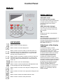
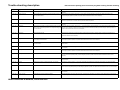
Control Panel
DISPLAY
MODE SWITCH
Automatic mode
(for heating circuits and HWS)
The boiler controls heating and domestic
hot water demands according to the
preset time program and outdoor
temperature.
HWS (Hot water storage)
The boiler only controls domestic hot
water storage according to the preset
time program.
Off
Heating is shut down, frost protection
remains active.
Manual mode
KEYBOARD
This setting allows for the performance of
tests for all electric functions and to
manually operate all drives in the case of
cleaning, troubleshooting or maintenance.
(See pages 10 and 11)
Button is used to scroll the display up
Adjustment of the display
contrast
Button is used to scroll the display down
To increase the display contrast,
simultaneously push the + button and the
button below the down arrow button.
Simultaneously pushing the - button and
the button below the down arrow button
conversely results in a decrease in
contrast. Holding the buttons while
increasing the contrast will result in
switching to minimum contrast, once the
maximum contrast has been reached and
exceeded. The same applies for holding
the buttons to decrease the contrast.
After the minimum setting has been
reached, the display will jump to
maximum setting. This is to assure that
pressing and holding any of the two
buttons, + or -, will always make the
display readable.
Button is used to scroll up a setting or raise the value of a
parameter such as time, temperature etc. In manual mode:
motors are rotating in forward direction, mixing motors are
opened, pump is switched on, etc.
Button is used to scroll down a setting or lower the value of a
parameter such as time, temperature etc. In manual mode:
motor are rotating in backward direction, mixing motors are
closed, etc.
Button is used to show the default display.
Button is used to confirm all parameters after adjustment and
to acknowledge errors after troubleshooting.
Button is used to move the cursor left (when setting time and
date)
Button is used to move the cursor right (when setting time and
date)
Button is used to enable and disable "Manual" mode.
Button is used to check the safety thermostat.
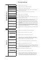
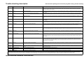
Extended info level
Costumer settings
Hours run
Controller
0,00 h
Displays the control's operation time.
Hours run
Ascheaustragung
0,00 h
Displays the operating hours of the ash removal system.
Counter
Cleaning system
0
Displays the number of automatic cleaning cycles.
Counter
Grate cycles
0
Total number of grate cycles (two per deashing cycles) i.e. number of deashing
cycles equals half of this number.
Hours run
Extract auger or Suction
motor
0,00 h
Displays the operating hours of the suction turbine / extraction auger.
Hours run
Ignition
0,00 h
Displays operation hours of the ignition.
Hours run
Stoker auger
0,00 h
Displays operation hours of the stoker auger.
Hours run
Heating
0,00 h
Stoker auger
Grate motor
Cleaning motor
Extract auger
0
0,0
0,0
0,0
mA
A
A
A
Cleaning system on
No. De-ash cycles
Act.
0 x
Set
4 x
De-ash Period
Act.
0 min
Set
180 min
temp. stretch: 120 min
Autom. Pellets
Filling at
run time
access from
Displays total heating time since commissioning. This includes ignition, firing, glow
bed retaining mode and ash removal.
50 min
200 min
Motor currents for all drives are shown here. The first line either shows the stoker or
extraction motor, depending on which of the two is currently running.
Displays the preset number (Set) of de-ashing cycles that are performed until the
cleaning system is turned on, and the actual number of de-ashing cycles that have
been performed since the last cleaning cycle (Act). After each de-ashing cycle, this
value raises by 1.
Displays the preset firing time (Set) after which de-ashing is performed. However deashing will only be performed when firing is stopped (glow bed retaining or OFF
mode) or after the preset stretch has expired eg.: 180+120=300min. Act shows the
interval time since the last deashing cycle.
The Stoker auger's run time before an automatic suction cycle is activated is shown
here.
push for 2 seconds
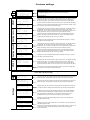
Pellets Classic 25-60
237291
SMS V4.2b
Mo, 21.01.2008 16:39:26
Dist. Circ
Dist. Circ Pump1 off
Displays the status of the long distance circuit. (if present)
EXT. HC
Ext-Setp.
Pump (Boiler)
Pump (HC-Mod1)
Pump (HC-Mod2)
Displays the status of the external heating circuit. (if present)
OFF
0°
off
off
off
return mixer < >
Act. Return-temp. 64°
Set Return-temp.
58°
Return pump
off
Info level
Displays the serial number together with the current date and time.
Displays set-point for the return temperature augmentation. (If a return mixer is
installed and activated). The bottom line shows which of the pumps is assigned to
perform return mixing. (return pump, buffer pump or FL pump 1)
HWS
53° Setp. 0°
Transp. 0% Air
0%
return 64° P. 50%
C02 12.6/11%F90 K85
Displays current boiler temperatures together with some additional parameters.
HWS LOADING 1
HWS actual temp
HWS Setpoint
Pump
Displays the hot water storage program currently running.
HC1 OFF
Act. 53°
Setp. 0°
Pump off
ACC
Top
ACC
ACC
OFF
52°
60°
off
HC2 OFF
Act. 35°
Setp.
0°
Pump off
loading
39°
Below
setp.
pump
OFF
54°
0°
off
ALTERN. HEAT OP.
Alt. heat temp.
HC valve
HEATING OFF
HWS 1
off
HWS 2
off
Heat circ 1
off
Heat circ 2
off
OT aug.
15°
OFF
22°
OFF
Displays the status of heating circuits (HC) 1 and 2. "B" indicates the flow set-point
reduction (while the hot water storage is being charged), "A" indicates the delay when
switching from heating to reduced temperature mode. ">" indicates that the mixer is
open, and "<" indicates that the mixer is closed.
Displays the buffer storage's current status. (if present)
Displays the status of an alternative heating source. (if present)
Displays the current status of the boiler, hot water storages and heating circuits.
(Alternative heating source, buffer storage, if they are present) and the average
outdoor temperature. A blinking D next to a heating circuits means that a digital
remote control is activated, while F stands for an analogue remote control.
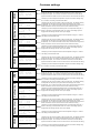
Costumer settings
Heating off
standard
display
Boiler
HC1
Boil 1
Outs.
30° Smoke
20° HC2
60° Boil 2
20° Puffer
HWS1
Heating circuit 1
Heating circuit 2
HWS 2
16:39
No.1 HWS 1
Day clock
On 17:00
On 00:00
Off 20:00
Off 00:00
Nr.2 HWS 1
Set temperature
Stand:
60°
60°
The "Standard display" shows the current status and temperatures.
displays date and time
This display can be set to show either a daily or weekly clock. Two different charging
periods can be preset. The system will automatically turn off upon reaching the
temperature set-point. The +/- buttons are used to set the time, while the left and
right arrow buttons are used to move the cursor. Enter is used to confirm the setting.
This display is used to adjust the temperature set-point for hot water storage 1 using
the +/- buttons. The setting is confirmed with Enter.
This display can be set to show either a daily or weekly clock. Two different heating
circuit periods can be preset. (The system will heat according to the outside
temperature). The +/- buttons are used to set the time, while the left and right arrow
buttons are used to move the cursor. Enter is used to confirm the setting.
No.3 HC 1
Day clock
* 06:00
* 15:00
( 09:00
( 22:00
No.4 HC 1
Day-time room temp.
14 . . 20 . . 26
IIIIIIIIII
*
No.5 HC 1
Reduced room temp..
8 . . 14 . . 20
IIIIIIIIIIIII
(
This display is used to adjust the desired day-time room temperature using the +/buttons. The setting is confirmed with Enter. If F is shown, the heating system is
equipped with an analogue remote control. (D for digital)
This display is used to adjust the reduced room temperature using the +/- buttons.
The setting is confirmed with Enter.
This display can be set to show either a daily or weekly clock. Two different heating
circuit periods can be preset. (The system will heat according to the outside
temperature). The +/- buttons are used to set the time, while the left and right arrow
buttons are used to move the cursor. Enter is used to confirm the setting.
No.6 HC 2
Day Clock
* 06:00
* 15:00
( 09:00
( 22:00
No.7 HC 2
Day-time room temp.
14 . . 20 . . 26
IIIIIIIIII
No.8 HC 2
reduced room temp.
8 . . 14 . . 20
IIIIIIIIIIIII
*
(
No.9 HWS 2
Day clock
On 17:00
On 00:00
Off 20:00
Off 00:00
No.10 HWS 2
Set temperature
Stand:
60°
60°
This display is used to adjust the desired day-time room temperature using the +/buttons. The setting is confirmed with Enter. If F is shown, the heating system is
equipped with an analogue remote control. (D for digital)
This display is used to adjust the reduced room temperature using the +/- buttons.
The setting is confirmed with Enter.
This display can be set to show either a daily or weekly clock. Two different charging
periods can be preset. The system will automatically turn off upon reaching the
temperature set-point. The +/- buttons are used to set the time, while the left and
right arrow buttons are used to move the cursor. Enter is used to confirm the setting.
This display is used to adjust the temperature set-point for hot water storage using
the +/- buttons. The setting is confirmed with Enter.
If an extension module for additional HCs is installed, they are shown here. (e.g. H1 = HWS 3) For more details
on this topic see the next page.
Settings
Only heating circuits that have been set to "available" in the commisioning level settings will be shown here.
Mo, 21.05.2007
displays the status of the boiler
21°
35°
55°
54°
No.11 Heating off above
Outside temp. 16°
Stand:
16°
This display can be used to preset a day and night time temperature limit using the +/buttons and Enter. Heating will be switched off upon reaching this temperature.
No.12 Heating off
reduced temp. day
above outs.temp. 8°
Stand:
8°
This display can be used to preset a reduced day time temperature limit using the +/buttons and Enter. Heating will be switched off upon reaching this temperature.
No.13 Heating off
reduced temp. night
above outs.temp. -5°
Stand:
-5°
This display can be used to preset a reduced night time temperature limit using the
+/- buttons and Enter. Heating will be switched off upon reaching this temperature.
No.14 Fill. Auto.
And suction time
a. 21:00
c. 00:00
b. 00:00
d. 00:00
In addition to the suction time already determined, this system will add additional
automatic suction periods whenever the stoker auger run time exceeds a preset
value (parameter R15=200-250min). To avoid suction periods during night, a
scheduled suction cycle at 21:00 has been preset by the manufacturer.
No.15 Holiday set.
Frost Protection
< not aktive >
Reduce
This display is used to cancel the holiday setting or switch to frost protection or
reduced temperature mode.
No.16 Holiday
01.08. 06:00 Uhr
to
06.08. 12:00 Uhr
This display is used to enter the date and time for start and end of frost protection or
reduced temperature mode.
No.20 Date/Time
Mo, 21.05.2007
16:39:26
This display is used to adjust the settings for time and date using the +/- buttons. The
cursor can be moved using the left and right arrow keys and the settings are
confirmed with Enter.
Costumer settings
HWS 3
Heating circuit 3
Heating circuit 4
HWS 4
Only heating circuits that have been set to "available" in the commisioning level settings will be shown here.
Extension module 1
H 1 HWS 3
Day Clock
On 17:00
Off 20:00
On 00:00
Off 00:00
H 2 HWS 3
Set temperature
Stand:
H 3 HC 3
Day clock
* 06:00
( 09:00
60°
60°
H 5 HC 3
Reduced room-temp.
8 . . 14 . . 20
IIIIIIIIIIIII
*
(
H 8 HC 4
Reduced room-temp.
8 . . 14 . . 20
IIIIIIIIIIIII
*
(
This display can be set to show either a daily or weekly clock. Two different charging
periods can be preset. The system will automatically turn off upon reaching the
temperature set-point. The +/- buttons are used to set the time, while the left and
right arrow buttons are used to move the cursor. Enter is used to confirm the setting.
On 00:00
Off 00:00
H 10 HWS 4
Set temperature
Stand:
This display is used to adjust the temperature set-point for hot water storage using
the +/- buttons. The setting is confirmed with Enter.
60°
60°
HWS5
Heating circuit 5
Heating circuit 6
HWS 6
H 11 HWS 5
Day clock
On 17:00
On 00:00
Off 20:00
Off 00:00
H 12 HWS 1
Set temperature
Stand:
60°
60°
If an extension module 2 is installed its parameters are shown here.
This display can be set to show either a daily or weekly clock. Two different charging
periods can be preset. The system will automatically turn off upon reaching the
temperature set-point. The +/- buttons are used to set the time, while the left and
right arrow buttons are used to move the cursor. Enter is used to confirm the setting.
This display is used to adjust the temperature set-point for hot water storage using
the +/- buttons. The setting is confirmed with Enter.
This display can be set to show either a daily or weekly clock. Two different heating
circuit periods can be preset. (The system will heat according to the outside
temperature). The +/- buttons are used to set the time, while the left and right arrow
buttons are used to move the cursor. Enter is used to confirm the setting.
H 13 HC 5
Day clock
* 06:00
* 15:00
( 09:00
( 22:00
H 14 HC 5
Day-time room temp.
14 . . 20 . . 26
IIIIIIIIII
H 15 HC 5
Reduced room-temp.
8 . . 14 . . 20
IIIIIIIIIIIII
This display is used to adjust the desired day-time room temperature using the +/buttons. The setting is confirmed with Enter. If F is shown, the heating system is
equipped with an analogue remote control. (D for digital)
This display is used to adjust the reduced room temperature using the +/- buttons.
The setting is confirmed with Enter.
Extension module 2
Only heating circuits that have been set to "available" in the commisioning level settings will be shown here.
This display is used to adjust the desired day-time room temperature using the +/buttons. The setting is confirmed with Enter. If F is shown, the heating system is
equipped with an analogue remote control. (D for digital)
This display can be set to show either a daily or weekly clock. Two different heating
circuit periods can be preset. (The system will heat according to the outside
temperature). The +/- buttons are used to set the time, while the left and right arrow
buttons are used to move the cursor. Enter is used to confirm the setting.
* 15:00
( 22:00
*
(
This display is used to adjust the desired day-time room temperature using the +/buttons. The setting is confirmed with Enter. If F is shown, the heating system is
equipped with an analogue remote control. (D for digital)
This display is used to adjust the reduced room temperature using the +/- buttons.
The setting is confirmed with Enter.
This display can be set to show either a daily or weekly clock. Two different heating
circuit periods can be preset. (The system will heat according to the outside
temperature). The +/- buttons are used to set the time, while the left and right arrow
buttons are used to move the cursor. Enter is used to confirm the setting.
H 16 HC 6
Day clock
* 06:00
* 15:00
( 09:00
( 22:00
H 17 HC 6
Day-time room temp.
14 . . 20 . . 26
IIIIIIIIII
H 18 HC 6
Reduced room-temp.
8 . . 14 . . 20
IIIIIIIIIIIII
*
(
H 19 HWS 6
Day clock
On 17:00
On 00:00
Off 20:00
Off 00:00
H 20 HWS 6
Set temperature
Stand:
This display is used to adjust the temperature set-point for hot water storage using
the +/- buttons. The setting is confirmed with Enter.
This display is used to adjust the reduced room temperature using the +/- buttons.
The setting is confirmed with Enter.
H 7 HC 4
Day-time room temp.
14 . . 20 . . 26
IIIIIIIIII
H 9 HWS 4
Day clock
On 17:00
Off 20:00
This display can be set to show either a daily or weekly clock. Two different charging
periods can be preset. The system will automatically turn off upon reaching the
temperature set-point. The +/- buttons are used to set the time, while the left and
right arrow buttons are used to move the cursor. Enter is used to confirm the setting.
This display can be set to show either a daily or weekly clock. Two different heating
circuit periods can be preset. (The system will heat according to the outside
temperature). The +/- buttons are used to set the time, while the left and right arrow
buttons are used to move the cursor. Enter is used to confirm the setting.
* 15:00
( 22:00
H 4 HC 3
Day-time room temp.
14 . . 20 . . 26
IIIIIIIIII
H 6 HC 4
Day clock
* 06:00
( 09:00
If an extension module 1 is installed its parameters are shown here.
60°
60°
This display is used to adjust the desired day-time room temperature using the +/buttons. The setting is confirmed with Enter. If F is shown, the heating system is
equipped with an analogue remote control. (D for digital)
This display is used to adjust the reduced room temperature using the +/- buttons.
The setting is confirmed with Enter.
This display can be set to show either a daily or weekly clock. Two different charging
periods can be preset. The system will automatically turn off upon reaching the
temperature set-point. The +/- buttons are used to set the time, while the left and
right arrow buttons are used to move the cursor. Enter is used to confirm the setting.
This display is used to adjust the temperature set-point for hot water storage using
the +/- buttons. The setting is confirmed with Enter.
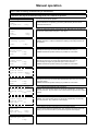
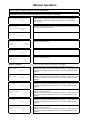
Manual operation
This setting fascilitates the performance of tests of all electrical functions and to manually control all
drives in case of cleaning, troubleshooting or maintenance!
Use the up and down arrow buttons to adjust settings!
All functions will only be performed as long as the + or - buttons are pressed.
Manual Operation
No.1 Manual
0,0 A
Grate
1x open/Clo. + Key
this line will show manual operation.
No.2 Manual
Grate
Open
Closed
Display for testing the function of the pusher grate. Manually move the grate into
opened and closed position using the + and - keys.
0,0 A
+ Key
- Key
No.3 Manual
0,0 A
Cleaning system
Start
After cleaning the boiler perform de-ashing using the pusher grate. Pressing the
+ button will lead to one pushing cycle of the grate whereby the ash will be
pushed into the ash box.
Used to test the function of and manually operate the cleaning system.
Caution: When the + button is released, the cleaning motor will proceed to it's
final position!
+ Key
No.3a Manual 0 mA
De-ash auger
Forward
+ Key
Back
- Key
Used to test the function and rotating direction of the de-ash auger motor.
Manually turn the auger in forward and backward direction using +/-.
Caution: Backwards operation will only be possible for a short time!
No.4 Manual
0 mA
Stoker auger
Forward
+ Key
Back
- Key
Used to test the function and rotating direction of the stoker auger motor.
Manually turn the auger in forward and backward direction using +/-.
Used for filling the auger, the grate will open to avoid overload.
Caution: Backwards operation will only be possible for a short time!
No.5 Manual mode
Suction motor
Filling level: empty
on
+ Key
Used to test the function of the pellet suction turbine. (if present)
No.6 Manual
0,0 A
Extract auger
Forward
+ Key
Back
- Key
Used to test the function and rotating direction of the extraction auger motor.
Manually turn the auger in forward and backward direction using +/- if stuck or
jammed by debris
Caution: Backwards operation will only be possible for a short time!
No.7 Manual
,0 A
Extract auger +Suction
Filling level:
empty
on
+ Key
Used to refill the intermediate bin after full restart.
Caution: The level indicator will turn off the auger automatically. To manually
turn it off press the - key. Be aware of the suction turbine's lag! (if suction turbine
present)
No.7a Manual
0,0 A
direct auger fill.
Filling level
empt/full
on
+ Key
Used to refill the extract auger manually after a full restart.
Caution: The level indicator will turn off the auger automatically! To manually
turn it off press the - key. (if there is a direct auger)
No.8 Manual
Ignition
Heat.+Fan
+ Key
Ign fan only. - Key
Used to test the function of the ignition fan and heating element.
If the fan doesn't start upon pressing the - key, check the connection of the fan
following the connection scheme. (Connections might be interchanged)
No.9 Manual mode
Exhaust gas fan
On
+ Key
Used to test the function of the exhaust gas fan.
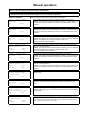
Manual operation
This setting fascilitates the performance of tests of all electrical functions and to manually control all
drives in case of cleaning, troubleshooting or maintenance!
Use the up and down arrow buttons to adjust settings!
All functions will only be performed as long as the + or - buttons are pressed.
No.10 Manual
HWS pump1(ACC Valve)
on
+ Key
Used to test the function or manually operate hot water storage pump 1. If the
heating system is equipped with a thermal buffer storage and intergrated hot
water storage, the buffer valve is also connected to this oulet. (See heating
circuit scheme)
No.11 Manual
HWS pump 2/
Ext./Dist.Heat.pump
On
+ Key
Used to test the function or manually operate hot water storage pump 2.
Optionally, an external pump or district heating pump can be connected or tested
here. (See heating circuit scheme)
No.12 Manual mode
HC pump
1
On
+ Key
Used to test the function or manually operate heating circuit pump 1.
No.13 Manual mode
Mixing valve 1
Open
+ Key
Closed
- Key
Used to test if mixing valve 1 opens when the + button is pressed and closes
when the - button is pressed.
No.14 Manual mode
HC pump
2
On
+ Key
Used to test the function or manually operate heating circuit pump 2.
No.15 Manual mode
Mixing valve 2
Open
+ Key
Closed
- Key
Used to test if mixing valve 2 opens when the + button is pressed and closes
when the - button is pressed.
Extension module 1
Can only be tested if heating circuit module 1 is installed!
No.16 manual mode
HWS pump
3
On
+ Key
Used to test the function or manually operate hot water storage pump 3.
Caution: This outlet is connected with extension module 1. If this module is not
connected, the message "extension module 1 not connected/defective" will be
displayed.
No.17 manual mode
HWS pump
4
On
+ Key
Used to test the function or manually operate hot water storage pump 4.
Caution: This outlet is connected with extension module 1. If this module is not
connected, the message "extension module 1 not connected/defective" will be
displayed.
No.18 manual mode
HC pump
3
On
+ Key
Used to test the function or manually operate heating circuit pump 3.
Caution: This outlet is connected with extension module 1. If this module is not
connected, the message "extension module 1 not connected/defective" will be
displayed.
No.19 Manual mode
Mixing valve 3
Open
+ Key
Closed
- Key
Used to test if mixing valve 3 opens when the + button is pressed and closes
when the - button is pressed.
Caution: This outlet is connected with extension module 1. If this module is not
connected, the message "extension module 1 not connected/defective" will be
displayed.
No.20 Manual mode
HC pump
4
On
+ Key
Used to test the function or manually operate heating circuit pump 4.
Caution: This outlet is connected with extension module 1. If this module is not
connected, the message "extension module 1 not connected/defective" will be
displayed.
No.21 Manual mode
Mixing valve 4
Open
+ Key
Closed
- Key
Used to test if mixing valve 4 opens when the + button is pressed and closes
when the - button is pressed.
Caution: This outlet is connected with extension module 1. If this module is not
connected, the message "extension module 1 not connected/defective" will be
displayed.
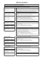
Manual operation
This setting fascilitates the performance of tests of all electrical functions and to manually control all
drives in case of cleaning, troubleshooting or maintenance!
Use the up and down arrow buttons to adjust settings!
All functions will only be performed as long as the + or - buttons are pressed.
Extension module 2
Can only be tested if heating circuit module 2 is installed!
No.22 Manual mode
HWS pump
5
On
+ Key
Used to test the function or manually operate hot water storage pump 5.
Caution: This outlet is connected with extension module 2. If this module is not
connected, the message "extension module 2 not connected/defect" will be
displayed.
No.23 Manual mode
HWS pump
6
On
+ Key
Used to test the function or manually operate hot water storage pump 6.
Caution: This outlet is connected with extension module 2. If this module is not
connected, the message "extension module 2 not connected/defective" will be
displayed.
No.24 Manual mode
HC pump
5
On
+ Key
Used to test the function or manually operate heating circuit pump 5.
Caution: This outlet is connected with extension module 2. If such an additional
module is not installed, the message "extension module 2 not
connected/defective" will be displayed.
No.25 Manual mode
Mixing valve 5
Open
+ Key
Closed
- Key
Used to test if mixing valve 5 opens when the + button is pressed and closes
when the - button is pressed.
Caution: This outlet is connected with extension module 2. If such an additional
module is not installed, the message "extension module 2 not
connected/defective" will be displayed.
No.26 manual mode
HC pump
6
On
+ Key
Used to test the function or manually operate heating circuit pump 6.
Caution: This outlet is connected with extension module 2. If this module is not
connected, the message "extension module 2 not connected/defective" will be
displayed.
No.27 Manual mode
Mixing valve 6
Open
+ Key
Closed
- Key
Used to test if mixing valve 6 opens when the + button is pressed and closes
when the - button is pressed.
Caution: This outlet is connected with extension module 2. If this module is not
connected, the message "extension module 2 not connected/defective" will be
displayed.
No.28 Manual mode
Return shunt pump
or ACC pump
On
+ Key
Used to test the function and manually operate the return shunt pump or buffer
storage pump.
No.29 Manual mode
HC valve
ON
+ Key
Used to test the function or to manually operate the heating circuit valve for
switching from boiler to buffer storage or from boiler to an alternative heat
source.
No.30 Manual mode
Fault light /
Ext./Dist.Heat.pump
On
+ Key
Used to test the function or manually operate the fault light. An external or long
distance heating pump can be connected and tested here as well. (See heating
circuit scheme)
No.31 Manual mode
Return mixer
Open
+ Key
Closed
- Key
Used to test if the return mixer opens when the + button is pressed and closes when the button is pressed. Caution: the mixer is "closed", when the boiler circuit is closed and
"open", when the return is open. While heating, the return temperature will rise when the
mixer is closed, and fall when the mixer is open.
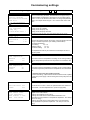
Manual operation
This setting fascilitates the performance of tests of all electrical functions and to manually control all
drives in case of cleaning, troubleshooting or maintenance!
Use the up and down arrow buttons to adjust settings!
All functions will only be performed as long as the + or - buttons are pressed.
No.34 Manual mode
Lambda Sen. 0.0mV
Boiler cold
Test start
+ Key
Used to test the function of the lambda sensor. When the + button is pushed,
the displayed current should reach a value of around -10mV within approximately
5 minutes. Values between -5 and -15 mV are within the acceptable range. Iif the
values are outside this range, a malfunction or incorrect connection of the sensor
will indicated. In the case of a calibrated sensor the correction value will be
displayed. Caution: the boiler needs to be cold (exhaust temp. < 50°C)
No.40 Manual mode
Boiler sensor
64°
Exh.gas sensor 148°
Outside sensor
-4°
Used to test the function of the temperature sensors by comparing the displayed
values to actual temperatures. Display: blank indicates the sensor is not
connected
Display: - - - indicates the sensor sensor is short circuited
No.41 Manual mode
ACC/alt.heat
54°
Return sensor
58°
HWS2 or ACC2
or Exh.temp sens.
OFF
Used to test the function of the temperature sensors and the exhaust
temperature sensor by comparing the displayed to actual temperature.
Display: blank indicates the sensor is not connected
Display: - - - indicates the sensor is sensor short circuited
The bottom line either shows the temperature of HWS 2, Buffer 2 or the exhaust
temperature sensor, while On indicates closed and Off indicates open.
No.43 Manual mode
HWS sensor 1
52°
HWS sensor 2
48°
No.44 Manual mode
HC1 sensor
53°
HC2 sensor
35°
Used to test the function of the temperature sensors by comparing the displayed
values to actual values.
Display: blank indicates the sensor is not connected
Display: - - - indicates the sensor is sensor short circuited
No.45 Manual mode
Remote cont. 1
Remote cont. 2 18°
Used to test the function of the remote control system. In the case of a digital
remote control, the status (Off, Night (Moon), Auto or Day (Sun)) is shown. In the
case of an analogue remote control with room sensor, the displayed temperature
can be compared to the actual temperature
Function check of an analogue remote control w/o room sensor Display: 21°
indicates being set to a fixed resistance valuet
Display: blank indicates the sensor is not connected
Display: - - - indicates the sensor sensor is short circuited
Caution: if the FR25 remote control is used, the mode switch has to be set to
"clock".
Extension module 1
Can only be shown if extension module 1 is installed!
No.46 Manual mode
HWS sensor 3
52°
HWS sensor 4
48°
No.47 manual mode
HC3 senosr
53°
HC4 sensor
35°
Used to test the function of the temperature sensors by comparing the displayed
and actual temperatures.
Display: blank indicates the sensor is not connected
Display: - - - indicates the sensor sensor is short circuited
No.48 Manual mode
Remote cont. 3 22°
Remote cont. 4 18°
see description no. 45 about testing the remote control's function
Extension module 2
Can only be shown if extension module 2 is installed!
No.49 Manual mode
HWS sensor 5
52°
HWS sensor 6
48°
No.50 manual mode
HC5 sensor
53°
HC6 sensor
35°
No.51 Manual mode
Remote cont. 5 22°
Remote cont. 6 18°
Used to test the function of the temperature sensors by comparing the displayed
and actual temperatures.
Display: blank indicates sensor is not connected
Display: - - - indicates sensor sensor is short circuited
see description no. 45 about testing the remote control's function
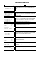
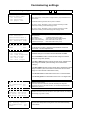
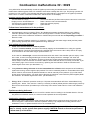
Comissioning settings
Commissioning settings: simultaneously press the + and - buttons for 3 sec.
Commissioning level
Param. Acc. to
Heating schematic
and instruction manual
from No 11
You've now accessed the commissioning level setting.
Before commissioning the boiler, all values have to be approved by a
certified installer and adjusted in agreement to the according heating
scheme. To do so use the down arrow button to change the parameter
display, then adjust values using the + and - buttons and confirm with
Enter.
to the Parameters
No.A1 HC 1
not available
pump only
< with mixer motor >
3 available settings:
Heating circuit not available
Heating circuit with pump only
Heating circuit with pump and mixer
on
Parameters A2 -A9 are not shown, if the "not available" option has been chosen.
motherboard
No.A2
HC 1
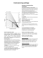
Inclination
Stand:
Adjustment range: 0,2...3,5
1.60
1.60
Describes the relation between the change of flow temperature and the
change of outside temperature. (see heating characteristics).
Recommended settings:
Floor heating
0,3...1,0
Radiation heating
1,2..2,0
Convection heating
1,5...2,0
The adjustment should only be carried out in small steps and over a
long time period.
No.A3 HC 1
Flow temperature
Minimum
30°
Stand:
30°
Adjustment Range: 1...80°C
No.A4 HC 1
Flow Temperature
Maximum
70°
Stand:
70°
Adjustment Range: 1...95°C
Lower limit for the flow temperature of heating circuit 1.During heating or
reduced temperature periods the flow temperature won't fall below this
limit.
Upper limit for the flow temperature of heating circuit 1. During heating
or reduced temperature periods the flow temperature won't exceed this
limit.
Be cautious when using floor heating systems!
To avoid overheating, a special electro-mechanical thermostat, capable
of cutting the power supply of the according heat circuit pump has to be
installed!
No.A5
HC 1
Run-time mixer
Stand:
Adjustment Range: 10...300s
90s
90s
No.A6 Remote HC1
FR30 remote contr.
< not available >
FR25 without r. sen.
FR25 room sensor
The actual mixer run-time - that is, the period between the closed and
opened state - has to be adjusted here. (check the type plate)
4 available settings
- digital remote control FR30
- heating circuit without remote control
- heating circuit with remote control FR25 but without a room
temperature sensor (therefore no temperature adjustment - use clamps
1 and 3 for wiring)
- heating circuit with remote control FR25 and a room temperature
sensor (automatic temperature adjustment - use clamps 1 and 2 for
wiring)
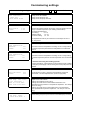
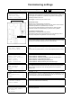
Comissioning settings
Commissioning settings: simultaneously press the + and - buttons for 3 sec.
No.A7 HC 1
<No dist.pump>
with dist. Heat. 1
at solar ACC
No.A8 HC 1
<Summer heating off>
Summer heating on
at switch HWS
Floor dry-out funct.
No.A9 HC 1
<Floor dry-out off>
Floor dry-out on
You may specify here, if there is a long distance heating pump. However, the
long distance heating pump will only work if one of it's associated pumps is
running.
Activate the (summer time) solar heating mode for the respective heating
circuit. The heating circuit will be switched on (in accordance with a specified
time scheme), as soon as the buffer storage's temperature exceeds a certain
level.
Caution: This will only work, if a solar buffer storage is present and the mode
switch is set to "HWS".
Activate the floor dry-out heating mode using this option. After this option is set
to "Floor dry-out on" a number of additional options (A9a-A9f) can be adjusted.
When done, set the mode switch to "Auto" or "HWS" to start the program.
Switch HWS/Auto
parameters A9a - A9f are not shown when this option is set to "off"
No.A9a HC 1
Flow setp.start/stop
20°
Stand:
20 °
Adjustment range: 10-30°C
No.A9b HC 1
Flow setp. increase
5°
Stand:
5°
Adjustment range: 1-10°C
No.A9c Incr./Reduce
< Every day >
after 2 days
after 3 days
after 4 days
after 5 days
The flow temperature will be raised by the amount specified in A9b after the
period chosen here has expired. While cooling down, the temperature will be
decreased by the amount specified in A9f during this period.
No.A9d HC 1
Flow set point max.
45°
Stand:
45°
Adjustment range: 25-60°C
No.A9e HC 1
Flow set point max.
Hold time
1T
Stand: 1day
Adjustment Range: 0-20 days.
No.A9f HC 1
Flow setp.reduct.
Adjustment range: 1-10°C
Stand:
10°
10°
Start- and end temperature for the floor dry-out program.
Temperature rise after the period specified in A9c has expired.
Upper limit for the flow temperature.
Specify the period during which the maximum flow temperature specified in
A9e will be held.
Temperature reduction after the period specified in A9c has expired.
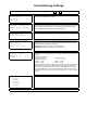
Comissioning settings
Commissioning settings: simultaneously press the + and - buttons for 3 sec.
No.A11 HC 2
<not available >
Pump only
with mixer motor
3 available settings:
Heating circuit not available
Heating circuit with pump only
Heating circuit with pump and mixer
on motherboard
Parameters A2 -A9 are not shown, if the "not available" option has been chosen.
No.A12
Adjustment range: 0,2...3,5
HC 2
Inclination
Stand:
1.60
1.60
Describes the relation between the change of flow tempreature and the
change of outside temperature. (see heating characteristics).
Recommended adjustment:
Floor heating
0,3..1,0
Radiation heating
1,2..2,0
Convection heating
1,5.. 2,0
The adjustment should only be carried out in small steps and over a
long time period.
No.A13 HC 2
Flow Temperature
Minimum
30°
Stand:
30°
Adjustment Range: 1...80°C
No.A14 HC 2
Flow Temperature
Maximum
70°
Stand:
70°
Adjustment Range: 1...95°C
Lower limit for the flow temperature of heating circuit 1. During heating
or reduced temperature periods the flow temperature won't fall below
this limit.
Upper limit for the flow temperature of heating circuit 1. During heating
or reduced temperature periods the flow temperature won't exceed this
limit.
Be cautious when using floor heating systems!
To avoid overheating, a special electro-mechanical thermostat, capable
of cutting the power supply of the according heat circuit pump has to be
installed!
No.A15
HC 2
Run-time mixer
Stand:
Adjustment Range: 10...300s
90s
90s
The actual mixer run-time - that is the period between closed and
opened state - has to be adjusted here. (check the type plate)
No.A16 rem. cont. HC2
FR30 digi. rem. cont.
< not available >
FR25 w/o room sens.
FR25 with room sens.
4 available settings
- digital remote control FR30
- heating circuit without remote control
- heating circuit with remote control FR25 but without a room
temperature sensor (therefore no temperature adjustment - use clamps
1 and 3 for wiring)
- heating circuit with remote control FR25 and a room temperature
sensor (automatical temperature adjustment - use clamps 1 and 2 for
wiring)
No.A17 HC 2
<No dist. pump>
With dist.Heat. 1
You may specify here, if there is a long distance heating pump. However, the
distance heating pump will only work if one of it's associated pumps is running.
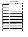
Comissioning settings
Commissioning settings: simultaneously press the + and - buttons for 3 sec.
at solar ACC
No.A18 HC 2
<Summer heating off>
Summer heating on
see HC1
at switch HWS
Floor dry-out funct.
No.A19 HC 2
<Floor dry-out off>
Floor dry-out on
see HC1
Switch HWS/Auto
No.A21 HC 3
<not available >
Pump only
with mixer motor
see HC1
on Extens.module 1
Parameters A22 -A29 are not shown, if the "not available" option has been chosen.
No.A31 HC 4
<not available >
pump only
with mixer motor
see HC1
On Extens.module 1
Parameters A32 -A39 are not shown, if the "not available" option has been chosen.
No.A41 HC 5
<not available >
Pump only
with mixer motor
see HC1
on Extens.module 2
Parameters A42 -A49 are not shown, if the "not available" option has been chosen.
No.A51 HC 6
<not available >
Pump only
with mixer motor
see HC1
on Extens.module
Parameters B52 -B59 are not shown, if the "not available" option has been chosen.
No.B1 HWS Tank 1
<available
not available
This option is only available, if extension module 1 has been installed. (if not,
an error message will tell you that a heating circuit module is not available)
This option is only available, if extension module 1 has been installed. (if not,
an error message will tell you that a heating circuit module is not available)
This option is only available, if extension module 2 has been installed. (if not,
an error message will tell you that a heating circuit module is not available)
This option is only available, if extension module 2 has been installed. (if not,
an error message will tell you that a heating circuit module is not available)
2
>
Set this option to not available, if hot water storage 1 is not installed. Control
for hot water storage 1 will be locked.
on motherboard
Parameters B2 - B7 are not shown, if the "not available" option has been chosen
No.B2 HWS tank 1
HWS temp.
Switch
different
6° Stand:
6°
Adjustment range: 1...40°
Start of charging: When the temperature falls below the specified value (minus
tolerance level). End of charging: As soon as the temperature reaches the set
limit (customer setting). However charging will only take place during specified
periods (customer setting)
No.B3 HWS tank 1
HWS temp.
Minimum
40° Stand:
40°
Adjustment range: 1...80°
If - during the time specified in B9 - the temperature falls below this level, the
hot water storage tank will be charged, regardless of the according time
program.
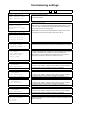
Comissioning settings
Commissioning settings: simultaneously press the + and - buttons for 3 sec.
Legionella prot. B1
No.B4 HWS tank 1
<Leg. protect. off>
Leg. protect. on
Activation of legionella protection.
See options B5 and B6.
Legionella prot. B1
No.B5 HWS tank 1
Legion. protect.
Set-Temperature 70°
Stand:
70°
Adjustment range: 10-75°C
A date and time for running the legionella protection heating program (T=70°C
as set in B5) may be specified with parameter B6. Make sure to choose the
heating period matching the charging times.
Caution: Make sure not to set the temperature level too high, so as to avoid
long heating periods and risk of burning if warm water is let out.
Legionella prot. B1
No.B6 Start-End B1
Mo -- -- -- -- -- -a. 17:00 c.00:00
b. 00:00 d.00:00
No.B7 HWS tank 1
<No dist. pump>
With dist.Heat. 1
You may specify here, if there is a long distance heating pump. However, the
distance heating pump will only work if one of it's associated pumps is running.
No.B11 HWS tank 2
available
< not available >
External pump
Dist. pump
The default setting for this option is "not available" for systems without a
second hot water storage tank. If instead of a second tank an external pump or
long distance heating pump is installed, this has to be specified here.
Parameters B11 or C7 are available for the external pump or long distance
heating pump, depending on which of the outlets is not in use.
on motherboard
Parameters B12 - B17 are not shown, if the "not available" option has been chosen
No.B21 HWS tank 3
available
< not available >
see HWS tank 1
on Extens.module 1
Parameters B22 - B27 are not shown, if the "not available" option has been chosen
No.B31 HWS tank 4
available
< not available >
see HWS tank 1
on Extens.module 1
Parameters B32 - B37 are not shown, if the "not available" option has been chosen
No.B41 HWS tank 5
available
< not available >
see HWS tank 1
on Extens.module 2
Parameters B42 - B47 are not shown, if the "not available" option has been chosen
No.B51 HWS tank 6
available
< not available >
see HWS tank 1
on Extens. Module 2
No.B90 Access all
HWS temp.minimum
On 06:00
Off 22:00
This option is only available, if heating circuit module 1 has been installed. (if
not, a fault will tell you that an extension module is not available)
This option is only available, if heating circuit module 1 has been installed (if
not, a fault will tell you that an extension module is not available)
This option is only available, if heating circuit module 2 has been installed (if
not, a fault will tell you that an extension module is not available)
This option is only available, if heating circuit module 2 has been installed (if
not, a fault will tell you that an extension module is not available)
o
Parameters B52 - B57 are not shown, if the "not available" option has been chosen
If during this time the temperature of the hot water storage falls below a
specified level (default=40°C), it will be charged to that level, regardeless of the
preset time program.
Comissioning settings
Commissioning settings: simultaneously press the + and - buttons for 3 sec.
No.C1 Pump select.
<Return shunt pump>
not available
ACC pump+1sens.
ACC pump+2 sens.
3 available settings in accordance with the HEATING SCHEME
Return shunt pump: If the system is equipped with a pump between the flow
and the return.
Not available: Meaning another return system is installed.
ACC pump + 1sens.: Necessary in case of a system according to buffer
scheme HP3 including a buffer discharging control.
ACC pump + 2sens.: Necessary in case of a system according to buffer
scheme HP4 including a buffer discharging and charging control.
No.C1a Return mixer
< not available >
Return mixer+LD-P.1
Return mixer+ACCPump
Ret. mixer+Ret. Pump
The return mixer can be assigned to one of the pumps using this option (see
heating scheme)
<not available>
: a different return mixer system
Return mixer+LD-P.1
: return mixer with a long distance pump
Return mixer+ACCPump : return mixer with an ACC pump
RL-Mischer+RL-Pumpe : return mixer with a return pump
Nr.C1b Return mixer
Run-time mixer
90s
stand
90s
Adjustment Range: 10...300s
No.C2 ACC./alt.Heat
< not available >
ACC + HWS integrated
ACC+HWS external
Alt. Heat solid
Alt. Heat oil/gas
The actual mixer run-time - that is the period between closed and
opened state - has to be adjusted here.
4 available settings in accordance with the HEATING SCHEME
Set to not available if neither a thermal buffer storage nor external
heating are being used. (default)
set to ACC + HWS integrated if a buffer storage with an integrated hot
water storage is installed. (internal heating coil or external heat
exchanger)
set to ACC+ HWS external if a buffer storage with a separated hot water
storage is installed. (set to ACC+HWS-int. if the buffer and hot water
storage are connected with a differential control)
set to Alt heat solid if the alternative heat source is a solid fuel boiler.
set to Alt heat gas/oil if the alternative heat source is an oil/gas boiler.
No.C4 ACC loading
ACC
Set temperature 60°
Stand:
60°
Only shown if C1 is set to ACC pump + 2 sens.
Adjustment range: 20-80°C
In case of an ACC with 2 sensors, the buffer will always be charged to
temperature set here. In this case C4=60°C, i.e. the lower temperature limit
represented by sensor 2.
No.C5 ACC.
Charging /
On 00:00
Off 00:00
Used to specify a constrained charging period, during which the temperature
specified in C4 will be held. Can be used to cover spike demands, for example
in the morning. (e.g. 04:00 - 10:00).
Oblig.
Day clock
On 00:00
Off 00:00
No.C6 Boiler
ext. Heating Circuit
Set-Temperature
60°
Stand:
60 °
Adjusting range: 1°...84°
Set-point boiler temperature during times when the external heating
circuit is active.
Comissioning settings
Commissioning settings: simultaneously press the + and - buttons for 3 sec.
No.C7
<Fault light
>
External Pump
Dist. Circ.pump 1
By default this outlet is assigned to the fault light. Parameters B11 (HWS 2) or
C7 (Fault light) are available for an external or long distance heating pump,
depending on which is not in use
1.Fault Light: Is lit when any sort of error occurs.
sketch plug :
2.External HC Pump:
(Remove plug J7 from the board, see scheme)
Using the port for "external heating circuit", the boiler will be heated until the
temperature specified in C6 (default=60°C) is reached.
The pump for the external heating circuit will switch on when the boiler
temperature matches the release value (L5), which is 50°C by default.
3.Long distance heating pump:
(Remove plug J7 from the board, see scheme)
The distance heating pump will operate when one of the heating circuit or
HWS pumps assigned to "long distance circuit" are running.
PLUG
An "EXTERNAL HC" can be used without assigning a pump for it.
To do so connect clamps 19 and 21 to the external contact point. When initially
connected, the external HC display will come up automatically.
No.C8 external HC
<no dist. pump>
with dist.Heat. 1
Shows if the long distance heating pump is assigned to the external heating
circuit.
The pump will only operate however, if one of the assigned pumps is running.
No.D1 Operat. mode
Direkt auger RAD
<single pt. suction>
direct auger
point suction
auger + Reservoir
Used to choose between different modes of pellet loading
= intermediate bin loaded manually
= intermediate bin loaded by extraction auger and suction turbine
= plant loaded by a direct extraction auger
= intermediate bin loaded using punctual suction
= intermediate bin directly loaded by the extraction auger
No.D2 Frost Protect.
Pump on below
Outside Temp.
1°
Stand:
1°
Value range: -30°...+20°
If the outside temperature falls below this value, all HC pumps will be started
and and heating circuits with a mixer will be adjusted to the temperature
specified in E2.
No.D3 Frost protect.
FlowSet-Temperature
7°
Stand:
7°
Value range: 1°...30°
If the mode switch is set to Off or HWS and either the flow temperature (in case
of a heating circuit or mixer) or boiler temperature under-run this value by 3°C,
the frost protection program will start automatically.
No.D4
without Lambda
< with Lambda
Choose if the boiler will be operated with or without a lambda sensor. (This can
be useful if the lambda sensor is defective)
>
No.D5 Changeover
Daytime temp.reduct.
On 06:00
Off 22:00
Specifies the times when changeover from day time to reduced temperature
mode will be performed.
Comissioning settings
Commissioning settings: simultaneously press the + and - buttons for 3 sec.
No.D6 Access
De-ash/clean
On 06:00
Off 22:30
Used to specify during which time de-ashing and automatic cleaning will be
performed. (to avoid irritation by noise)
No.D7 HC 1-6 Summer
shutdown
delay time
120min stand: 120min
Value range: 0...240 min
Summer shutdown: Heating will be shut down, if the outside temperature underruns the corresponding value (Nr.11) for the duration specified here. Delay
time = time before the temperature reduction phase starts.
No.D8 summer time
no switch over
<autom.switchover>
Choose if summer time switchover should be performed automatically.
No.D9 Day/week time
<day clock
>
weekly clock
HC+HWS week clock
Choose whether a day clock or weekly clock are shown in the customer level
interface. Use + and - to choose an option and confirm the setting with Enter.
Day clock: HCs and HWS set to day clock
Weekly clock: HCs set to weekly clock, HWS to daily
HC+HWS week clock: Both circuits set to weekly clock
No.D10
Number of blocks
Weekly clock
2
Stand:
2
Value range 1...7
Choose how many different blocks for the weekly clock can be specified by the
customer.
z.B.. HC1 using 2 blocks :
3a.Heating Circuit 1
3b. Heating Circuit 1
MO TU WE TH FR SA ---- --- --- --- --- --- SU
* 06:00 * 15:00
* 06:00 * 00:00
) 09:00 ) 22:00
) 22:00 ) 00:00
Block a will be active monday to saturday from 6:00 to 9:00 and 15:00 to 22:00
while block b will be active on sundays from 6:00 to 22:00. The left and right
keys are used to browse through the weekdays. Weekdays can be enabled
with + and disabled with -. To choose between times, again use the left and
right keys and perform adjustment of the values using + and -. Confirm settings
with Enter.
No.E1 Language
< german
french
italian
english
spanish
Specify your language here.
>
Finish by pressing the Standard button when adjusting all settings is done.
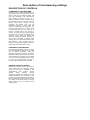
Description of Comissioning settings
DESCRIPTION OF CONTROLS
CHARGING OF THE HWS TANK
Charging of the hot water storage (HWS) will
only be active when the mode switch is set to
HWS or Auto and the respective HWS has
been set to "available" in the commissioning
level settings. Furthermore there is a
distinction between normal charging during
the specified period and minimum charging.
During normal mode, charging will be
controlled and started when the set
temperature (default = 60°C) taking into
account a certain tolerance range (zB. : 606=54°C) is being under-run. It makes sense
to charge the HWS only once a day, eg. to
choose a charging time in the morning or
evening. If it turns out that a single charging
cycle does not cover the hot water demand,
additional cycles should be added. The
minimum charging will however avoid that no
warm water is available by starting HWS
charging when the minimum temperature setpoint (default = 40°C) is being under-run.
Moreover, charging will be started in chimney
sweep mode and will be inactive during
LEGIONELLA PROTECTION
If the legionella protection program is active,
day and temperature levels for every HWS
can be defined separately, using the
paramater "legionella protection". By default
legionella protection at a temperature of 70°C
will be performed on mondays at 17:00. Make
sure not to set the temperature level too high,
to avoid long heating periods and risk of
burning if warm water leaks from the HWS.
HEATING CIRCUIT CONTROL
Heating circuit control will only be active in
"Auto" mode when the respective heating
circuit has been set to "available" in the
commissioning
level
settings.
Several
different
modes
(heating,
reduced
temperature, off) will be run depending on the
outside temperature, the necessity of frost
protection and the time programs specified in
the commissioning settings. In addition to that
all, heating circuits will be active in chimney
sweep mode and will be inactive during
holiday periods.
Description of Comissioning settings
Heating: In this mode the flow temperature
will be calculated based on the oustide
temperature, desired room temperature in
heating mode and inclination (see flow
temperature calculation). The boiler will
perform
heating until the calculated
temperature has been reached. In case of a
heating circuit with a mixer the set-point will
be raised by a certain amount. (default=10°C)
Reduced Temperature: In this mode the
flow temperature will be calculated based on
the outside temperature, desired room
temperature in reduced temperatur mode and
inclination.
Changeover from heating to reduced
temperature:
In this mode the flow
temperature will be gradually reduced from
heating mode to reduced temperature mode.
Outside temperature shutdown: There are
three different modes for outside temperature
shutdown, depending on the active heating
program and the time.
During heating mode, heating will be stopped,
when the averaged outside temperature
exceeds the set-point specified as no.
11=16°C.
During daytime reduced temperature mode,
heating will be stopped when the averaged
outside temperature exceeds the set-point
specified as no. 12=8°C.
During nightime reduced temperature mode,
heating will be stopped when the averaged
outside temperature exceeds the set-point
specified as no. 13=-5°C. aus. Summer
shutdown:
Even if the averaged outside temperature
falls below the set-point for summer
shutdown, heating will only be restarted, if the
limit is under-run for a specified time
(D7=120min)
DAYTIME ROOM TEMPERATURE
(Customer settings No.4,7, H4, H7, H14,H17
) This display is used to adjust the desired
day time room temperature between 14 and
26°C. The centre position means a set-point
of 20°C. To allow for a consistent room
temperature - regardless of the outside
temperature conditions - an accurate
adjustment of the heating characteristics and
appropriate dimensioning of the heating
system in accordance with the underlying
heat demand calculation are needed.This setpoint is valid for directly controlled heating
circuits and additional mixed circuits.
Adjustments of this set-point should only be
carried out in small steps and after an interval
of 2-3 hours.
Default setpoint = 20°C
Description of Comissioning settings
REDUCED TEMPERATURE SETPOINT
(Customer settings no.5, 8, H5, H8, H15 and
H18) These displays can be used to adjust
the desired room temperature during reduced
temperature mode. Values may range
between 8 and 20°C. To allow for a consistent
room temperature - regardless of the outside
temperature conditions - an accurate
adjustment of the heating characteristics and
appropriate dimensioning of the heating
system in accordance with the underlying
heat demand calculation are needed. The
reduced temperature set-point is valid for
directly controlled circuits as well as additional
mixed circuits. It is important that adjustments
of this value are performed stepwise and over
along period.
EXCESS HEAT FUNCTION
When heating circuits are inactive, the boiler
will be shutdown, while pumps and mixers will
continue to operate to ensure that excess
heat will be utilized until the limit set as
M2=40°C is being under-run.
HOT WATER STORAGE PRIMACY
During HWS charging the HWS will be
prioritised, resulting in a reduction of the
heating circuit's temperature set-point. When
charging is finished, the heating circuit's
temperature set-point will be reset to its
previous value.
This however only applies for mixed circuits.
In the case of a pumped circuit, the pump will
simply be inactive during charging.
HOLIDAY SHUTDOWN
Available settings for holiday shutdown
(no.15) are "inactive", "frost protection" and
"reduced temperature". If holiday shutdown is
enabled and the specified date and time
(no.16) are reached, all heating circuits will
operate according to the chosen program
("frost protection" or "reduced temperature")
during the set period.
HEATING CIRCUITS AND OVERTEMPERATURE
If the boiler temperature exceeds the safety
limit specified as (M1=90°C), all heating
circuits will be activated and operated in
accordance with an outside temperature
(M1a) of -10°C. This temporary mode of
operation is necessary to remove the excess
heat from the boiler. As a result the blinking
text "safety control" will be shown in the
topmost line of the display.
Description of Comissioning settings
FROST PROTECTION FUNCTION
The frost protection function will be enabled
when the outside temperature falls below the
limit specified in D2=1°C. As a result, heating
circuit pumps will be switched on. If the boiler
or flow temperature fall below the limit
D3=7°C, the boiler will be activated.
BLOCKING PROTECTION
To prevent blocking, heating circuits pumps
will be activated and mixers will be opened for
one minute on monday at 12:00.
FLOOR DRY-OUT
The procedure will be discribed for Heating
circuit 1 (Note that other HCs correspond to
different parameters).
To initially start the dry-out program, the
corresponding parameter A9 (Floor dry-out
on/off) must be set to "ON". Then the initial
and terminal temperature set-point for the
flow temperature has to be specified as
parameter A9a (flow setp.start/stop=20°C).
After
the
period
specified
in
A9c
(Incr./Reduce=daily) has expired, the flow
temperature will be raised by the amount A9b
(Flow setp. increase=5°C). When the
maximum temperature as set in A9d (Flow set
point max.) has been reached, the
temperature will be held for the period
specified in A9e (Flow set point max. stop
time). After that, the flow temperature will be
reduced by the amount specified in A9f (Flow
setp.reduct.=10°C) according to the period
specified in A9c (Incr./Reduce=daily) until the
temperature A9a (flow setp.start/stop=20°C)
is reached. The heating circuit will then take
up normal operation and automatically set
A9a to "Off".
REMOTE CONTROL FR 25
with room sensor
Connect using clamps 1 and 2
In addition to the actual sensor this remote
control is equipped with a a rotation disk that
allows fine adjustment of the room
temperature set-point by +/- 2-3°C. The mode
switch can be used to choose between the
functions "permanent day time mode",
"permanent reduced temperature mode" or
"automatic".
Caution: The remote control type has to be
specified in the commissioning level settings.
Description of Comissioning settings
Site of installation
Note that the site of installation must be
carefully chosen. It's important that the
remote control is not directly exposed to
sunlight nor in an area affected by breeze.
Furthermore the control should not be close
to a fireplace or radiator to ensure that the
temperature measured by the sensor is
representative
of
the
actual
room
temperature. It makes sense to install the
remote control in the room that is used most
commonly (like the living or dinning room).
However the room must not contain additional
heating devices (like a tile stove). If there is a
radiator with a thermostat valve, it must be
adjusted to a higher temperature than the setpoint in the control, to avoid an influence on
the room sensor. (Such an influence could
lead to temperature changes in the flow and
ultimately to other rooms being warmer or
colder than expected) However radiators in all
other rooms except the one where the remote
is installed should have a thermostat valve.
REMOTE CONTROL FR 25
without room sensor
Connect using clamps 1 and 3
In addition to the actual sensor this remote
control is equipped with a a rotation disk that
allows fine adjustment of the room
temperature setpoint by +/- 2-3°C. The mode
switch can be used to choose between the
functions "permanent day time mode",
"permanent reduced temperature mode" or
"automatic".
Caution: The remote control type has to be
specified in the commissioning settings.
Site of installation
If clamps 1 and 3 are used, the room sensor
is inactive. Therefore the remote control can
be installed in any room. Radiators should be
equipped with thermostat valves.
Remote control fixing:
The remote control should be fixed on the
same level as lightswitchs are. To do so
remove the front button, loosen the screw and
take off the casing.
Fault light:
The remote control is fitted with a red LED
that can be connected with the boiler. It will
then show any error or alert that may occur.
Connection:
2-pin cable (2 x 0,75) with fault light LED
4-pin cable (4 x 0,75) without fault light LED
(Clamps: 4=plus und 5=minus)
Description of Comissioning settings
DIGITAL REMOTE CONTROL
FR30
The digital remote control can be used for
remote control from a neighbouring building
or installed directly in the living space. (there
is no room sensor). A maximum of one FR 30
can be used per boiler, while there can be up
to two FR 30s per heating circuit module.
(Connected with the CAN-Bus) The handling
is in accordance with the boiler's control and
the same options for programming heating
circuits, manual testing and assigning the
mode switch to a heating circuit are available.
Mode switch:
"HEATING" means permanent day time
operation
"REDUCED TEMPERATURE" means
permanent reduced temperature mode
"AUTO" means operation following the time
program
"OFF" means that the heating circuit is shut
down
(the frost protections is active nevertheless)
Caution: The remote control type has to be
specified in the commissioning settings.
Site of installation:
The remote control can be installed in the
heating room (neighbouring building
containing the heating circuit module) or
directly inside the living space (there is no
room sensor).
EXTENSION MODULES 1 AND 2
To extend both the heating and boiler circuits,
up to two extension modules can be
connected. The modules are connected to
the boiler's board using BUS cables (CANBUS). The extension module's adress switch
has to be set to 1, which is the default setting.
(extension module 1 = HC 3+4 and boiler
circuit 3+4)
Description of Comissioning settings
BUFFER CONTROL
Solar buffer control HP1 with integrated
hot water storage:
The buffer tank is only heated by the solar
collector and not by the boiler. First of all it is
checked if the solar buffer contains enough
heat to cover the flow's assesed demand. If
that is the case, the HC valve is brought to
the A - AB position (buffer operation), until the
temperature falls below the HC set-point. As
soon as this happens, the boiler is restarted
and the HC valve is reset to the B - AB
position (boiler operation). The temperature
of the HWS is checked during charging
periods and heating is applied by the boiler if
needed. During HWS charging cycles, the
HWS charging pump will also bring the buffer
valve to the A - AB position. The buffer tank is
only charged in the area of the HWS, while
the remaining area is reserved for the solar
heating system.
Parameter setting: C2 set to “ Buffer HWS
int. “
Solar buffer control HP2 with external
boiler
The thermal buffer storage is only loaded by
the solar collector. First of all it is checked if
the solar buffer contains enough heat to
cover the flow's assesed demand. If that is
the case, the HC valve is brought to the A AB position (buffer operation), until the
temperature falls below the HC set-point. As
soon as this happens the boiler is started
again and the HC valve is reset to the B - AB
position (boiler operation). The temperature
of the HWS is checked during HWS charging
time and heating is applied if needed. A
differential regulation is needed to allow for
HWS charging from the solar buffer.
Solar buffer regulation HP3 with integrated
or external boiler
The thermal buffer storage is heated by a
solar collector and a boiler. The heating
circuits will drain heat from the buffer until the
buffer temperature falls below the heating
circuit temerature limit. As a result heating will
be turned on and the buffer storage will be
charged. In the case of an external boiler a
differential regulation will be needed to allow
for boiler loading from the solar buffer.
Parameter setting: set to
C2 set to “ Buffer HWS int.“ and no.C1 auf
“ACCpump+1sens.”
C2 set to “ Buffer HWS ext.“ and no.C1 auf
“ACCpump+1sens.”
Description of Comissioning settings
Solar buffer control HP4 with integrated or
external boiler
The boiler will charge the thermal buffer
storage until the temperature set-point
specified in no. C4 = 60°C is reached (sensor
2). Upon reaching this limit the pellet boiler
will shut down and excess heat mode will be
activated. The heating circuits will drain heat
from the buffer until the specified temperature
limit is under-run (sensor 1). The plant will be
restarted and the buffer storage will be
recharged. In addition the HWS temperature
will be checked and charging cycles will be
applied if necessary. A differential regulation
is needed to allow charging of an external
boiler using the buffer storage. Charging the
HWS will also lead to the buffer storage being
loaded up to the limit specified by sensor 2.
Constrained charging:
Can be used to cover spike demands or
selectively charge the thermal storage.
Parameter no.C5 is used to specify an
interval (this could be 06:00-10:00) during
which constrained charging will be performed.
Charging will be performed up to the limit
specified by sensor 2. (no.C4=60°C)
Parameters: set to
No.C2 set to “ Buffer HWS int. “ & no. C1 auf “ ACCpump+
No.C2 set to “ Buffer HWS ext. “ & no. C1 auf “ ACCpump
Summer time bathroom heating
(with a solar solar buffer tank)
This program allows to heat bathrooms (by
the means of floor heating or radiators) solely
with heat from the solar buffer. To allow this,
the mode switch must be set to "HWS" and
the corresponding heating circuit's parameter
"Summer time bath heating" must be set to
"ON".
EXTERNAL HEATING SOURCE
SOLID FUEL OR OIL/GAS
Solid fuel: Check whether the external
heating source has reached it's temperature
set-point (O10=60°C). If that is the case, the
HC valve will be brought to the A - AB
position (external heating mode) while the
pellet boiler is shut down. In external heating
mode, the mode switch position "Auto" will
activate all heating circuits as well as the
HWS circuit, while "HWS" will only activate
the HWS circuit. As soon as the external
heating circuit's temperature underruns the
set-point temperature minus tolerance range
No.O11=2°C (60-2 = 58°C), the pellet boiler
will be restarted after the period specified in
No.O12=15min has expired. According to
that, the HC valve is brought back to the B AB position (boiler operation). The mixer
control will react based upon the averaged
outside temperature, unless a safety
temperature level (M1=83°C) is being overrun. In that case the outside temperature will
be
temporarily
set
to
M1a=-10°C.
Description of Comissioning settings
Oil/gas: Generally speaking the procedure
corresponds with what has been said for solid
fuels whereby the control will however work in
accordance with the usual timed and outside
temperature shutdown programs.
Flue gas temerature monitor: Should both
boilers be connected to the same chimney,
the pellet boiler will be shut down by the
external boiler's flue gas temperature
monitoring system (connected to clamps 86
and 87). The HC valve will however remain in
the B-AB position (pellet boiler) until the
external source takes over. The rest of the
EXTERNAL HEATING CIRCUIT
Clamps 19 and 21 have to be connected with
the external contact point (potential-free), if
an additional external heating circuit is
needed. Upon first connection the customer
setting display for external heating circuits will
be automatically brought up. If an external
pump is needed, it can either be assigned
using the comsissioning level parameter B11
(if HWS 2 or a distance heating pump are not
needed) or C7 (if a fault light is not needed).
The boiler's temperature set-point - while the
external heating circuit is active - can be set
in
commissioning
level
setting
C6
(default=60°C). If an external pump is
assigned and this value has been adjusted, it
is necessary to also adjust the external
pump's release temperature parameter L19
(service-settings, default=64°C). This value
should be approximately 5-10°C lower than
the boiler's temperature set-point.
Installateur-Einstellungen
EXTERNAL SENSOR
The external sensor should be installed at about one
third of the total building height (however at least 2
meters above the ground) and on the coldest side of
the building (north or north-east side). Note that any
source of heat (from a chimney, direct sunlight, etc.)
could lead to wrong temperature values and must
therefore be thoroughly avoided. Also make sure that
the cable outlet is directed towards the ground to
prevent water from intruding into the sensor. Use a 2wired cable for the electrical installation. (for the
minimum diameter see the connection scheme)
BOILER-, HOT WATER TANK SENSOR
FLOW-, BUFFER-, EXT. HEATING- SENSOR
(depending on the heating scheme)
All of the sensors are immersion sensors, connected
with cast on cables. An immersion sleeve is available
for the hot water tank-, buffer- and ext. heating
sensors. The flow sensor should be placed 50 after the
circulation pump. The sensor can be tightly attached
using the included brass casing and tightening strap.
Before attaching the casing, apply the included heatconductive paste to the contact point. Furthermore,
make sure to avoid buckling of the sensor cables. If the
cables are too short, you can extend them (for
minimum diameters see the connection scheme).
Resistance values
Boiler sensor
Hot water storage sensor
Flow sensor
Return sensor
in °C
-20
-10
0
10
15
20
25
30
35
40
45
50
55
60
65
70
75
80
85
90
95
100
Remote Control
FR25
in Ohm
resistances
measured in
922
Automatic mode (clock symbol)
960 with the switch in middle position
1000 should be in the range of 3340 3650 Ohm.
1039
(independent from the room
1058
temperature)
1077
1097
1116
1136
1155
1174
1193
1213
1232
1252
1270
1290
1309
1328
1347
1366
1385
CHIMNEY SWEEP BUTTON
This is a button that allows the chimney sweeper to manually turn on
and shut down the boiler when performing an emission check.
SAFETY THERMOSTAT CHECK
All heating circuit and boiler pumps are inactive during
this check. Press the TÜV-button until the safety
thermostat is being cut out.
Operating with this button disables all the other
programs. Heating will be performed with full load and
assuming a very low outside temperature while the
heating circuits distribute as much heat as possible. To
allow this, control- and thermostat valves have to be
opened manually. This function will automatically
terminate after 2 hours.
Comissioning settings
Heating characteristics
(Inclination)
The proportion between a change of flow
temperature and a change of outside temperature
is given by the heating characteristics and can be
separately adjusted for every heating circuit. The
curves in the left chart are based on the
assumption of a room temperature set-point of
20°C (and assume that the remote control's switch
is in middle position). For different room
temperature set-points the curves can be shifted in
parallel.
For example:
An assumed HC with the following characteristics:
Inclination: 1,5
Room temperature setpoint: 20°C
Outside temperature: 0°C
Boiler is in heating mode
Applying the characteristics for this example leads
to a flow temperature of 50°C.
Adjustments of the heating characteristics must
only be carried out in small steps and over a long
period.
An accurate adjustment of the heating
characteristics will lead to a constant room
temperature (at the set-point level) that is
unaffected by the outside temperature.
Reduced temperature mode:
During reduced temperature operation the HC
pump will remain active in accordance with the
scheduled program. The flow temperature will be
assessed using reduced heating chracteristics
(which correspond to the lowered temperature
level). However, the minimal flow temperature setpoint will not be undercut.
Economy mode:
If the outdoor temperature exceeds the set-point
values specified in no.12 and no.13 during reduced
temperature operation, all heating circuits will
automatically be shut down. Reduced temperature
mode is subdivided in day time and night time
mode and both phases can be specified
separately.
1. A time for the change from day time to night
time has to be specified in D5.
2. Outside temperature levels for automatic
shutdown can be separately specified for day and
night. Shutdown will be performed when the
temperature level (no.11) is reached.
Remote control FR25 not installed
The desired room temperature can be specified
separately for each HC in the customer settings.
Remote control FR25 installed
There are two modes of operation:
With a room sensor
The actual room temperature will be automatically
adjusted to match the set-point. In addition the
temperature can be manually adjusted by 2-3°C
using the rotation disk on the remote control.
Without a room sensor
This mode must be chosen if the room contains an
additional heat source (such as a tiled stove).
Again the temperature can be manually adjusted
by 2-3°C using the rotation disk on the remote
control.
Trouble-shooting description
Disconnect the polarity proof connector plug befor solving Trouble shooting
Report no. Origin
Reason/Problem
Solution (when done solving the problem push the Enter button)
Display is blank and none of the green lights on the I/O
board are lit
Fuse F16 is broken or connection (clamps1,3) could be interrupted; level
indicator or STB defective.
Change fuse F16 (see the according scheme) or check the connection at clamps 1 and 3; check level indicator and STB connections!
Fuse F10 or control panel are broken
Change fuse F16 (see the according scheme), check the ribbon cable that connects the board and the control panel, contact the service department if those
measures can't remove the problem.
-"-
and green light H3 is not lit (while H4-H6
are)
-"-
and green light H3 is glowing
Ribbon cable isn't correctly connected or control panel is broken.
Check the ribbon cable or replace the cable or the control panel;
-"-
2 black bars that are displayed
EPROM is missing or plugged in incorrectly, control panel is broken
Plug in an EPROM at the backside of the control panel (according to the scheme on the guard plate) ; replace EPROM if it was plugged in incorrectly or
replace the control panel;
----
Display light not lit
Display light is broken
Contact the service department, replace the control panel;
----
Fault light doesn't work
Fuse F17 destroyed by short circuit or fault light not connected
fix the short circuit; correctly connect D40 or fault light;
001
Safety thermostat (STB)
Over temperature at boiler or STB connection jammed
Cool down the boiler below 90°C; remove STB protection cap and press the button, else have STB connection checked by an electrician; (short term
emergency operation is possible, see "operation without hardware test" at the end of error description)
002
Overcurrent stoker auger
Combustion chamber jam-packed, stoker auger clogged with slag or debris
jamming rotary gate valve
While mode switch is set to "Manual"
- open the pusher grate (no.2) and where required, remove jammed debris or slag;
- check stoker auger, if the motor doesn't work correctly there most likely is debris stuck in the rotary gate valve; unscrew lid and remove pellets and debris;
-contact the service department if the motor still doesn't work properly;
003
Overcurrent extraction auger
Extraction auger motor not connected properly or defective (Capacitor);
Extraction auger jammed (water or humidity in the storage room); Level
indicator defective or not adjusted properly;
Debris stuck in the extract auger;
004
Thermal protection extraction auger
Extraction auger rough-running, jam-packed or jammed by debris; auger motor Treat like error no. 003; indication for this fault if the motor has been rough-running for a while orerror no. 003 occurs repeatedly.
(capacitor) defective.
005
Pusher grate rough-running
Pusher grate rough-running
Empty ash box - then press Enter. Run ash removal by pushing the + button while display no.3 is shown in "Manual mode". Then use the + and - buttons to
check if the pusher grate is working properly while display no.2 is shown in "Manual mode" (the current must not excceed 1,2A), otherwise contact the
service department;
006
Overcurrent pusher grate
Pusher grate jammed
see no. 005
007
Pusher grate won't open
Neither the open end position nor the closed end position have been correctly In "Manual" operation mode check if the pusher grate can be fully opened/closed using the +/- buttons; If it can't, contact the service department;
reached.
008
Pusher grate won't close
The closed end position hasn't been reached correctly (while the open end
position has).
see no. 007
009
Overcurrent cleaning device
Cleaning device is rough-running
In "Manual" operation mode, check if the cleaning device is rough running. If the current is close to or above 5A contact the service department;
0010
Flue gas sensor connected incorrectly
Reverse polarity (can only happen when commissioning the boiler) or I/O boardHave connection polarity checked by an electrician, else replace the sensor or the I/O board;
defective.
0011
Flue gas sensor interrupted
Sensor not connected or connection interrupted.
Unscrew the extraction auger's maintainance lid and remove jammed pellets, check the storage room for water leaks or humidity; try to run the motor in both
directions while the mode switch is set to "Manual"; Check the auger's direction of rotation by pressing the + and - buttons. If no jammed parts can be found,
check or replace the motor and capacitor;
While the mode switch is in "Manual" position and either display no.7 or no. 7a is shown, check the level indicator and it's orange diode as follows:
- if the display shows "empty" and the level indicator diode is lit while the intermediate bin is jammed, replace the level indicator;
If there is a pellet suction turbine, a jammed or defect turbine may be the origin If there is a suction turbine, perform the following steps while in "Manual" mode:
of the problem.
- briefly rotate extract auger (no.6) backwards, remove both hoses, remove jammed material and empty the hoses;
- start the suction turbine (no.5) and check it for free pass, where required clean the turbine;
Contact the service department if you find brown deposits.
After correction of defects, Press ENTER !
Connect sensor or replace connection; check clamps and make sure that plugs 74 and 75 are connected firmly, else replace sensor or I/O board;
Trouble-shooting description
Report no. Origin
Disconnect the polarity proof connector plug befor solving Trouble shooting
Reason/Problem
Solution (when done solving the problem push the Enter button)
0012
Boiler sensor short circuited
Sensor or connection short circuited.
Have sensor and connection checked by an electrician (see resistance values in chapter commissioning settings); replace the sensor with another sensor, if
there's a different error replace the sensor. If the same erroris shown, replace the I/O board;
0013
Boiler sensor interrupted
Sensor not connected or connection interrupted.
Connect sensor, or change connection/check clamps, make sure that clamps 72-73 are connected firmly; replace the sensor with another sensor, if there's a
different error replace the sensor. If the same fault is shown, replace the I/O board;
0014
HWS tank sensor short circuited
Sensor or connection short circuited.
see no. 0012; this error can be bypassed by pressing Enter, however it will remain on the display to remind the customer that it needs to fixed;
0015
HWS tank sensor interrupted
Sensor not connected or connection interrupted.
see no. 0012; this fault can be by passed by pressing Enter, however it will remain on the display to remind the customer that it needs to fixed;
0016
Outside sensor short circuited
Sensor or connection short circuited.
see no. 0012 and no. 0014
0017
Outside sensor interrupted
Sensor not connected or connection interrupted.
see no. 0013 and no. 0015
0018
Flow sensor HC1 short circuited
Sensor or connection short circuited.
see no. 0012 and no. 0014
0019
Flow sensor HC1 interrupted
Sensor not connected or connection interrupted.
see no. 0013 and no. 0015
0020
Flow sensor HC2 short circuited
Sensor or connection short circuited.
see no. 0012 and no. 0014
0021
Flow sensor HC2 interrupted
Sensor not connected or connection interrupted.
see no. 0013 and no. 0015
0022
Remote control HC1 short circuited
Remote control or connection short circuited.
see no. 0012 and no. 0014
0023
Remote control HC1 interrupted
Remote control not connected or connection interrupted.
see no. 0013 and no. 0015
0024
Remote control HC2 short circuited
Remote control or connection short circuited.
see no. 0012 and no. 0014
0025
Remote control HC2 interrupted
Remote control not connected or connection interrupted.
see no. 0013 and no. 0015
0026
Ignition time over-run
The flue gas temperature rise didn't exceed the set-point value specified in P11While in "Manual" operation mode check if:
during the period specified in P5 (in the the service department level settings); - the stoker auger (no.4) is running smoothly and delivering pellets
Reason may be that there is insufficient fuel supply, the ignition is defective, the- the ignition device (no.7) is working properly
flue gas sensor isn't situated in the flue gas tube or that the combustion
- the pusher grate (no.2) can be opened and closed completely
chamber contains too much ash or slag.
- the combustion chamber is clogged with slag
- the flue gas sensor is installed correctly
0027
Flue gas temperature under-run
While firing, the flue gas temperature under-runs the temperature specified in While in "Manual" operation mode check if:
K8 during the period specified in K7 in the the service department level settings- the stoker auger (no.4) is running smoothly and delivering pellets
Reasons may be that there is too little or no fuel at all, that there is too much - the pusher grate (no.2) can be opened and closed completely
ash or that the burning chamber is clogged with slag.
- the combustion chamber is clogged with slag
- the flue gas sensor is installed correctly
0028
Allowed CO2 stop time overrun
contact error of the lambda sensor, lambda sensor or I/O board defective.
0029
Combustion malfunction
Combustion failed due to missing fuel supply; ignition doesn't work.
Lambda sensor is dirty, clean the lambda sensor and check its function in "Manual" operation mode (no.34); have clamps and plugs checked by an
electrician, otherwise replace the lambda sensor; the boiler can be run without a lambda sensor (commissioning settings, D4) until the sensor has been
replaced;
Firing can't be started; See combustion malfunction no. 0029 at the end of the error description;
0030
Batteries empty, change batteries
Batteries powering date/time memory are close to being empty.
Change batteries during operation to avoid loss of the date and time setting; When changing batteries while the boiler is shut down, you have to redo the
time/date settings. Other settings, however, won't be lost;
0031
Lambda sensor defective
Contact error of the lambda sensor, lambda sensor or I/O board defective.
see no. 0028; this error can only occur in "Manual" mode after checking (no.34) or calibrating (no.60) the sensor;
0032
Maximum time for filling over-run
Pellet delivery not working properly.
Check pellet transport from the storage room; make sure that the storage room contains enough pellets, else remove the extraction auger's maintenance lid
and check if the auger is delivering pellets; check if bridging occured inside the storage room;
0033
Cleaning device not in rest position
The cleaning device's motor doesn't return to its rest position; the motor could Connect the motor correctly (plugs 29-32) or check the connection between the motor and the I/O board; contact the service department personell if you ca
fix the problem on your own or replace the motor or I/O board;
be connected incorrectly or the I/O board could be defective.
After correction of defects, Press ENTER !
Trouble-shooting description
Report no. Origin
Reason/Problem
0034
Buffer sensor 1 / Ext. Heat sensor short
circuited
Sensor or connection short circuited.
0035
Buffer sensor 1 / Ext. Heat sensor
shortinterrupted
Sensor not connected or connection interrupted.
Disconnect the polarity proof connector plug befor solving Trouble shooting
Solution (when done solving the problem push the Enter button)
see no. 0012 and no. 0014
see no. 0013 and no. 0015
0036
Buffer sensor 2 short circuited
Sensor or connection short circuited.
0037
Buffer sensor 2 interrupted
Sensor not connected or connection interrupted.
see no. 0013 and no. 0015
0038
Over current pusher grate
Pusher grate rough-running
In "Manual" operation mode check if the pusher grate is rough-running by pressing the + and - keys; Contact the service department if the current exceeds
0,9A;
0039
HWS tank sensor 2 short circuited
Sensor or connection short circuited.
see no. 0012 and no. 0014
0040
HWS tank sensor 2 interrupted
Sensor not connected or connection interrupted.
see no. 0013 and no. 0015
0041
Over current ash removal motor warning
Ash box almost full or ash removal auger rough-running
Empty ash box and check if the ash removal motor is rough-running; ("Manual" operation mode, no. 3a)
0042
Over current ash removal motor
Ash box jam-packed or ash removal auger jammed by debris.
Empty ash box and check if the ash removal motor is rough-running. ("Manual" operation mode, no. 3a) If that is the case, remove and clean the ash remo
motor and the ash removal area; when unsuccessful, contact the service department;
Ash removal motor not connected
Ash removal motor not connected or motor or I/O board defective.
Make sure the ash removal motor is connected correctly and that the plugs are firmly connected; If that doesn't fix the error, contact the service departmen
replace the motor or I/O board; (short term emergency operation is possible, see "operation without hardware test" at the end of fault description)
Ash box lid open
Ash box was opened when the ash removal motor started.
Check whether the ash box and its lid are positioned properly or have the end switch lid (cables and clamps) checked by an electrician; Call the service
department or change I/O board if all of the above fails; (short term emergency operation is possible, see "no hardware test" at the end of error description)
Return temperature not reached
The return's minimum limit has been undercut for more than 60 minutes. The Check the position of the return sensor (see heating scheme); replace the return pump or replace it with a larger pump. Check the function of the return mixer
return mixer might be defective or too small. The first and second time this error(if there is one); Contact a fitter; CAUTION: This problem might affect the life cycle of your boiler!
occurs there will be a warning. If it occurs a third time, the boiler will be shut
down.
0046
Return sensor short circuited
Sensor or connection short circuited.
see no. 0012 and 0014
0047
Return sensor interrupted
Sensor not connected or connection interrupted.
see no. 0013 and 0015
0062
GSM-module interrupted
Ribbon cable or GSM-connection or power supply interrupted.
Check the ribbon and GSM- cable and replace where required; Check the power supply (230VAC) or replace the GSM module;
0063
GSM-module, internal error
Internal connection between the GSM-control module and GSM-sending
module defective.
Check connection or replace the GSM module;
0064
GSM-module, SIM card missing
The sending module doesn't contain a SIM card or the PIN query hasn't been Insert a SIM card or disable the PIN query;
removed.
0065
GSM-module, no signal
The GSM-module couldn't send a text message because the SIM card's credit Recharge your SIM card or have it unlocked by the service provider; use a mobile phone from the same service provider to test if you can get a signal. Also
is depleted or a connection to the the service department provider could not be try repositioning or extending the antenna;
established.
0066
GSM-Modul, wrong software version
The Eprom-software of the GSM module and the boiler control unit don't match.Replace the GSM-module or update the software accordingly;
0067
Incorrect parameters
Internal error in the parameter memory.
Check parameters, and make adjustments where necessary; change the boiler control unit if the error persists despite the changes;
0100
Data transmission EM 1
No connection with extension module 1.
Set the extension module's adress switch to "1"; check HC's connection and bus wiring as well as fuse F23 (see board scheme); replace extension module
1;
0101
0102
ADC-Fault in EM 1
Zero-point error ext. module 1
Extension module 1 thermometry defect.
Control of outlets in extension module 1 defect
Replace extension module 1;
Replace extension module 1;
0043
0044
0045
After correction of defects, Press ENTER !
see no. 0012 and no. 0014
Trouble-shooting description
Report no. Origin
Disconnect the polarity proof connector plug befor solving Trouble shooting
Reason/Problem
Solution (when done solving the problem push the Enter button)
0103
0104
0105
0106
0107
0108
0109
0110
0111
0112
0113
0114
0120
HWS tank sensor 3 short circuited
HWS tank sensor 3 interrupted
HWS tank sensor 4 short circuited
HWS tank sensor 4 interrupted
Flow sensor 3 short circuited
Flow sensor 3 interrupted
Flow sensor 4 short circuited
Flow sensor 4 interrupted
Remote control HC3 short circuited
Remote control HC3 interrupted
Remote control HC4 short circuited
Remote control HC4 interrupted
Data transmission EM 2
Sensor or connection short circuited.
Sensor not connected or connection interrupted.
Sensor or connection short circuited.
Sensor not connected or connection interrupted.
Sensor or connection short circuited.
Sensor not connected or connection interrupted.
Sensor or connection short circuited.
Sensor not connected or connection interrupted.
Remote control or connection short circuited.
Remote control not connected or connection interrupted.
Remote control or connection short circuited.
Remote control not connected or connection interrupted.
No connection with extension module 2.
see no.0020 - 0031
see no.0020 - 0031
see no.0020 - 0031
see no.0020 - 0031
see no.0020 - 0031
see no.0020 - 0031
see no.0020 - 0031
see no.0020 - 0031
see no.0020 - 0031
see no.0020 - 0031
see no.0020 - 0031
see no.0020 - 0031
Set the extension module's adress switch to "2"; check HC's connection and bus wiring as well as fuse F23 (see board scheme); replace extension module
2;
0121
0122
0123
0124
0125
0126
0127
0128
0129
0130
0131
0132
ADC-error in EM 2
Zero-point error ext. module 2
HWS tank sensor 5 short circuited
HWS tank sensor 5 interrupted
HWS tank sensor 6 short circuited
HWS tank sensor 6 interrupted
Flow sensor 5 short circuited
Flow sensor 5 interrupted
Flow sensor 6 short circuited
Flow sensor 6 interrupted
Remote control HC5 short circuited
Remote control HC5 interrupted
Extension module 2 thermometry defect
Control of outlets in extension module 1 defect
Sensor or connection short circuited.
Sensor not connected or connection interrupted.
Sensor or connection short circuited.
Sensor not connected or connection interrupted.
Sensor or connection short circuited.
Sensor not connected or connection interrupted.
Sensor or connection short circuited.
Sensor not connected or connection interrupted.
Remote control or connection short circuited.
Remote control not connected or connection interrupted.
Replace extension module 2;
Replace extension module 2;
see no.0020 - 0031
see no.0020 - 0031
see no.0020 - 0031
see no.0020 - 0031
see no.0020 - 0031
see no.0020 - 0031
see no.0020 - 0031
see no.0020 - 0031
see no.0020 - 0031
see no.0020 - 0031
0133
0134
0200
0201
Remote control HC6 short circuited
Remote control HC6 interrupted
Wrong software version
Boiler module not assigned or CAN
interrupted
Remote control or connection short circuited.
Remote control not connected or connection interrupted.
Software verswions of the boiler control unit and digital remote control don't
No connection with the boiler.
see no.0020 - 0031
see no.0020 - 0031
Update the boiler control's and remote control's sofware accordingly; (matching EPROM softwares)
Boiler control unit not assigned; check power supply and BUS wiring or replace the remote control;
0202
Interfering BUS-configuration of two control Two or more remote controls assigned to the same heating circuit.
modules
Correct parameter Z2 of the digital remote control;
0211
Digital remote control 1 not connected
No connection with HC1's digital remote control
Check parameter Z2 and the BUS wiring; check fuse F23 (see board scheme); replace the digital remote;
0212
Digital remote control 2 not connected
No connection with HC2's digital remote control
Check parameter Z2 and the BUS wiring; check fuse F23 (see board scheme); replace the digital remote;
0213
Digital remote control 3 not connected
No connection with HC3's digital remote control
Check parameter Z2 and the BUS wiring; check fuse F23 (see board scheme); replace the digital remote;
0214
Digital remote control 4 not connected
No connection with HC4's digital remote control
Check parameter Z2 and the BUS wiring; check fuse F23 (see board scheme); replace the digital remote;
0215
Digital remote control 5 not connected
No connection with HC5's digital remote control
Check parameter Z2 and the BUS wiring; check fuse F23 (see board scheme); replace the digital remote;
0216
Digital remote control 6 not connected
No connection with HC6's digital remote control
Check parameter Z2 and the BUS wiring; check fuse F23 (see board scheme); replace the digital remote;
After correction of defects, Press ENTER !
Trouble-shooting description
Report no. Origin
Disconnect the polarity proof connector plug befor solving Trouble shooting
Reason/Problem
Solution (when done solving the problem push the Enter button)
Contact the service department; replace I/O board (short term emergency operation is possible, see "operation without hardware test" at the end of error
description)
4010..4017
Extraction auger motor
Extraction auger motor control defective
4020..4027
Extraction auger motor
Extracion auger motor not connected or connection interrupted; if there is no Fix the extraction auger's connection, check plugs no. 4 and 7 (clamp 7 must be connected) as well as the wiring; Readjust parameter D1 in the
extract auger, check the corresponding parameter D1 and readjust accordingly;commisioning level settings accordingly; contact the service department or replace the motor or I/O board if the above procedure doesn't fix the problem;
motor or I/O board defective.
(short term emergency operation is possible, see "operation without hardware test" at the end of error description)
4030..4037
Extraction auger motor
Extraction auger motor short circuited
Fix the short circuit. Change fuse F15 (see board scheme) and check plugs no. 4 and 7 as well as the wiring; Contact the service department or an
electrician or replace the motor or I/O board if the above procedure doesn't fix the problem;
4110..4117
Suction turbine
Suction turbine control defective
Contact the service department; replace I/O board (short term emergency operation is possible, see "operation without hardware test" at the end of error
description)
4120..4127
Suction turbine
Suction turbine not connected or connection interrupted; if there is no suction Fix the suction turbine's connection, check plugs no. 11 - 13 as well as the wiring; readjust parameter D1 in the commisioning level settings accordingly;
turbine, check the corresponding parameter F1 and readjust accordingly; motorcontact the service department or replace the I/O board if the above procedure doesn't fix the problem; (short term emergency operation is possible, see
or I/O board defective.
"operation without hardware test" at the end of error description)
4130..4137
Suction turbine
Suction turbine short circuited.
4210..4217
Heating circuit control
Heating circuit-, boiler-, buffer- or circulation pump or mixer affected by separat Check clamps 35 - 61 for separate source voltage or defective components; Contact the service department or an electrician or change the I/O board. (short
source voltage or I/O board defective.
term emergency operation is possible, see "operation without hardware test" at the end of error description)
4220..4227
Heating circuit control
HC pump 1, HC pump 2, HC 1 mixer, HC 2 mixer, boiler-, buffer- or circulatuionFix the short circuit, check fuse F13 (see board scheme) and the wiring. Contact the service department or an electrician or change the I/O board if the
pump short circuited.
problem persists;
4310..4317
Stoker auger
Stoker auger motor control defective.
Contact the service department or change the I/O board; (short term emergency operation is possible, see "operation without hardware test" at the end of
error description)
4320..4327
Stoker auger
Stoker auger not connected; motor or I/O board defective.
Check the motor's connection (clamps no. 22-25) and wiring; Contact the service department or replace the motor or I/O board if the problem persists; (short
term emergency operation is possible, see "operation without hardware test" at the end of error description)
4330..4337
Stoker auger
Stoker auger motor short circuited.
Fix the short circuit, check fuse F18 (see board scheme) and clamps 22-25 as well as the wiring; Contact the service department or an electrician or replace
the motor or I/O board if the problem persist; (short term emergency operation is possible, see "operation without hardware test" at the end of error
description)
4410..4417
Draught fan
Draught fan control defective.
Contact the service department or change the I/O board; (short term emergency operation is possible, see "operation without hardware test" at the end
oferror description)
4420..4427
Draught fan
Draught fan not connected or connection interrupted; fan or I/O board
defective.
Check the fan's connection (clamps no. 8-10) and wiring; Contact the service department or an electrician or replace the fan or I/O board if the problem
persists; (short term emergency operation is possible, see "operation without hardware test" at the end of error description)
4430..4437
Draught fan
Draught fan or I/O board short circuited.
Fix the short circuit, check fuse F20 (see board scheme) and clamps 8-10 as well as the wiring; Contact the service department or an electrician or replace
the fan or I/O board if the problem persist; (short term emergency operation is possible, see "operation without hardware test" at the end of error description)
4510..4517
HC valve / ext. pump
HC valve/ext. pump control defective.
Contact the service department or change the I/O board; (short term emergency operation is possible, see "operation without hardware test" at the end of
error description)
4520..4527
HC valve / ext. pump
HC valve/ext. pump control not connected or defective.
Check the clamps (80-82) and wiring for both components. Contact the service department or an electrician or replace thecomponents or I/O board if the
problem persists. (short term emergency operation is possible, see "operation without hardware test" at the end of error description)
After correction of defects, Press ENTER !
Fix the short circuit. Change fuse F21 (see board scheme) and check all plugs and clamps as well as the wiring; Contact the service department or an
electrician or replace the I/O board if the above procedure doesn't fix the problem; (short term emergency operation is possible, see "operation without
hardware test" at the end of error description)
Trouble-shooting description
Report no. Origin
Disconnect the polarity proof connector plug befor solving Trouble shooting
Reason/Problem
Solution (when done solving the problem push the Enter button)
4530..4537
HC valve / ext. pump
HC valve/ext. pump short circuited.
Fix the short circuit, check fuse F14 (see board scheme) and clamps 80-82 as well as the wiring of both components. Contact the service department or an
electrician or replace the defective component or I/O board if the problem persists. (short term emergency operation is possible, see "operation without
hardware test" at the end of error description)
4610..4617
Ignition fan
Ignition fan control defective.
Contact the service department or change the I/O board. (short term emergency operation is possible, see "operation without hardware test" at the end of
error description)
4620..4627
Ignition fan
Ignition fan not connected; ignition fan or I/O board defective.
Check the fan's connection (clamps no. 26-28) and wiring. Contact the service department or an electrician or replace the fan or I/O board if the problem
persists. (short term emergency operation is possible, see "operation without hardware test" at the end of error description)
4630..4637
Ignition fan
Ignition fan short circuited.
Fix the short circuit, check fuse F19 (see board scheme) and clamps 26-28 as well as the wiring. Contact the service department or an electrician or replace
the fan or I/O board if the problem persists. (short term emergency operation is possible, see "operation without hardware test" at the end of error description)
4710..4717
Ignition heater
Ignition heater control defective.
Contact the service department or change the I/O board; (short term emergency operation is possible, see "operation without hardware test" at the end of
error description)
4730..4737
Ignition heater
Ignition heater not working.
Check fuse F19 (see board scheme) and clamps 26-28 as well as the wiring; Contact the service department or an electrician or replace the ignition unit or
I/O board if the problem persist; (short term emergency operation is possible, see "operation without hardware test" at the end of error description)
4810..4817
Cleaning device
Cleaning device not connected or short circuited.
Check fuse F11 (see board scheme) and clamps 29-32 as well as the wiring; Contact the service department or an electrician or replace the motor or I/O
board if the problem persist; (short term emergency operation is possible, see "operation without hardware test" at the end oferror description)
4820..4827
Cleaning device
Cleaning device not working.
Check the cleaning device's connection with the I/O board (clamps 29-32) and the wiring. Contact the service department or an electrician or replace the
motor or I/O board if the problem persists. (short term emergency operation is possible, see "operation without hardware test" at the end of error description)
4830..4837
Cleaning device
Cleaning device not connected correctly or motor defective.
Fix the cleaning device's connection with the I/O board (clamps 29-32). Contact the service department or an electrician or replace the motor or I/O board if
the problem persist. (short term emergency operation is possible, see "operation without hardware test" at the end of error description)
4910..4917
Lambda sensor heating
Lambda sensor not connected or sensor or I/O board defective.
Fix the lambda sensor's connection and check the wiring and clamps 76-79. Contact the service department or an electrician or change the I/O board if the
problem persists. Reassign parameter D4 in the commissioning level settings to "without lambda sensor" until the sensor has been replaced. CAUTION: The
commissioning level settings can only be accessed after the boiler has been relaunched and hardware tests have been disabled as described at the end of
error description.
4920..4927
Lambda sensor heating
Lambda sensor or sensor heating short circuited or defective.
Check the wiring and connection of the sensor (clamps 76-79); replace fuse F22 where needed; contact the service department or an electrician or change
the I/O board if the problem persists; reassign parameter D4 in the commissioning level settings to "without lambda sensor" until the sensor has been
replaced; CAUTION: The commissioning level settings can only be accessed after the boiler has been relaunched and hardware tests have been disabled
described at the end of error description;
5020..5027
Pusher grate
Pusher grate not connected or I/O board defective.
Check the pusher grate's connection (clamps 33-34); Contact the service department or an electrician or replace the I/O board.if the problem persists (short
term emergency operation is possible, see "operation without hardware test" at the end of error description)
Defective data transmission between
boards.
Fuse F12 defect, flat ribbon connection interrupted, I/O board or control unit
defective.
Green lights H5 and H6 are not lit. Change fuse F12 (see board scheme). Contact the service department or an electrician or replace the I/O board or ribbon
cable if the problem persists;
Wrong software I/O board
I/O board not compatible with the software.
Contact the service department or replace the I/O board.
Initializing error buffer, only load default
settings
Not an actual error, but logged in the error buffer.
Contact an electrician if this message is shown repeatedly; (Might be caused by power failure or loose contact)
Hardware restart
Not an actual error, but logged in the error buffer.
Contact an electrician if this message is shown repeatedly; (Might be caused by power failure or loose contact)
6001
6002
6101-6102
0
1000
Short term emergency operation "no hardware test": If the error is clearly caused by a defect on the I/O board, meaning that all connected components are working properly, the control can be run in emergency operation without hardware test for a short term (until the
service department technician arrives) 1. Disconnect the control from the grid (plug or main switch) (display is dark). 2. Press the lower left "Space" button while restarting the power supply. The 4th line of the display will show the message "no hardware test". Once the
message appears you can release the button. System selftests are now disabled, but only until power supply is cut off again. Make sure to check all potentially defective components in "Manual" operation mode to ensure that no other errors persist.
After correction of defects, Press ENTER !
Combustion malfunctions Nr.: 0029
Your pellet boiler will automatically control the ignition process using the lambda sensor. Combustion
malfunctions will be triggered if the CO 2 emission sinks below a safety limit of 5% (no. S4) during a period of 5
minutes (no. S5) or longer. This indicates that either the pellet delivery is interrupted or the ignition procedure
failed. "Error no. 0029 - combustion malfunction" will be shown on the display.
Possible reasons that could cause the malfunction:
The Intermediate bin is empty............................
Level indicator defective (insufficient suction periods in the case of a suction turbi
Bridging occured in the intermediate bin............. Debris or excessive dust in the intermediate bin
The stoker auger is running backwards............
Stoker auger defective (capacitor)
The combustion chamber is overfilled................
Ignition defective
Follow these instructions to fix the problem:
1.
Remove the ash box and insert the control sheet.
2.
Acknowledge the error by pressing "Enter" (the displayed message should be blinking now). While in
"Manual" operation mode (and display no.2 is shown) press the + button until the pusher grate is fully
opened. Check if the combustion chamber is overfilled and proceed with the corresponding procedure if
that is the case.
3.
While in "Manual" operation mode (no.4), press the + button until the stoker auger starts (and the pusher
grate is being opened) and check if pellets are being delivered.
if no pellets are being delivered:
a.
Check if the intermediate bin contains pellets:
In case of a suction turbine, this can be checked by tapping the intermediate bin or using the syphols
contained the lid. Check the level indicator (the indicator light is lit when the bin is full) if the bin is empty.
Then refill the bin and the stoker auger. (as described in c.)
In the case of a direct auger, remove the maintenance lid and check if the transition piece is empty. If that
is the case, check if the orange diode light is lit and if the display shows the message "full" when the
intermediate bin is filled. The absence of either of these two signals indicates a defective level indicator.
Check clamps 14 and 15 and the connection cables to ensure that the device is correctly connected. If you
can't find any sign of an incorrect connection try replacing the level indicator. Refill the extraction and
stoker augers when done. (as described in c.)
b.
If no pellerts are being delivered while the intermediate bin is filled and all components of the delivery
system are running, the bin might be jam packed. This can be caused by debris or accumulated dust. Open
the lid of the bin and remove all pellets and debris or dust to manually fix the problem. (If you find dust to
be the cause of the problem, you might want to discuss the high dust content with the pellet supplier) Refill
the extraction- and stoker augers when done. (as described in c.)
c.
Filling: While in "Manual" operation mode (no.7/7a) start the automatical refill of the intermediate bin by
pressing the + button. Then use the + button (no.4 active) to deliver pellets (with the stoker auger) until they
fall onto the control sheet. (this takes up to 3 minutes) Then set the mode switch to "Auto" and restart the
boiler.
if pellets are being delivered:
Start up the boiler in "Auto" mode and check if the stoker motor is rotating in the forward direction. If there
are phases of backward rotation, the motor must be replaced as soon as possible.
Combustion chamber overfilled:
Remove the green heating device (after loosening the attachement screw) and check the function of the
device using the + button while in "Manual" operation mode (no.8). Replace the heating element if the
emitted air is cool, or replace the device if no air is emitted at all.
If the problem is solved or no problem was found, restart the system in "Auto" mode, press
Enter or shortly cut the system from power supply. CAUTION: Check no.2 must be performed
to allow start up of the boiler.
Parameter-list
Scheme Date:
No.
EPROM:
............ Signature:
Customer Settings
Menu
No. 1
Description
Hot water storage 1 day clock
Customer set-point I
Default
ON 17:00 00:00
OFF 20:00 00:00
see parameter "Weekly clock" (No. D9 in the commissioning settings)
Mo Tu We Th Fr Sa Su
No. 1a Hot water storage 1
ON 17:00 00:00
OFF 20:00 00:00
No. 1b Hot water storage 1
off
No. 2
No. 3
Hot water storage 1 set-point temperature
Heating circuit 1 day clock
60°
ON 6:00 15:00
OFF 9:00 22:00
see parameter "Weekly clock" (No. D9 in the commissioning settings)
Mo Tu We Th Fr Sa ...
No. 3a Heating circuit 1
ON 06:00 15:00
OFF 09:00 22:00
.........................Su
No. 3b Heating circuit 1
ON 06:00 00:00
OFF 22:00 00:00
No. 4
No. 5
No. 6
HC1 daytime roomtemp. set-point
HC1 daytime reduced roomtemp. set-point
Heating circuit 2 day clock
20°
16°
ON 06:00
OFF 09:00
15:00
22:00
see parameter "Weekly clock" (No. D9 in the commissioning settings)
Mo Tu We Th Fr Sa ...
No. 6a Heating circuit 2
ON 06:00 15:00
OFF 09:00 22:00
.........................Su
No. 6b Heating circuit 2
ON 06:00 00:00
OFF 22:00 00:00
No. 7
No. 8
No. 9
HC2 daytime roomtemp. set-point
HC2 daytime reduced roomtemp. set-point
Heating circuit 2 day clock
No. 10 Hot water storage 2 temperature set-point
Extension module 1
H 1 Hot water storage 3 day clock
H2
H3
Hot water storage 3 temperature set-point
HC3 day clock
H4
H5
H6
HC3 daytime roomtemp. set-point
HC3 daytime reduced roomtemp. set-point
HC4 day clock
H7
H8
H9
HC4 daytime roomtemp. set-point
HC4 daytime reduced roomtemp. set-point
Hot water storage 4 day clock
H 10
Hot water storage 4 temperature set-point
Extension module 2
H 11 Hot water storage 5 day clock
20°
16°
ON 17:00 00:00
OFF 20:00 00:00
60°
ON 17:00 00:00
OFF 20:00 00:00
60°
ON 06:00
OFF 09:00
20°
16°
ON 06:00
OFF 09:00
15:00
22:00
20°
16°
ON 17:00 00:00
OFF 20:00 00:00
60°
ON 17:00 00:00
OFF 20:00 00:00
H 12
H 13
Hot water storage 5 temperature set-point
HC5 day clock
H 14
H 15
H 16
HC5 daytime roomtemp. set-point
HC5 daytime reduced roomtemp. set-point
HC6 day clock
H 17
H 18
H 19
HC6 daytime roomtemp. set-point
HC6 daytime reduced roomtemp. set-point
Hot water storage 6 day clock
H 20
Hot water storage 6 temperature set-point
60°
11
12
13
14
15
16
20
Heating off above outside temp.
Heating off during day time reduced temp.
Heating off during night time reduced temp.
Autom. filling and suction time
Holiday mode
Holiday
Date / Time
16°
8°
-5
*
only for systems with suction turbine
No.
No.
No.
No.
No.
No.
No.
15:00
22:00
60°
ON 06:00
OFF 09:00
15:00
22:00
20°
16°
ON 06:00
OFF 09:00
15:00
22:00
20°
16°
ON 17:00 00:00
OFF 20:00 00:00
21:00 Uhr
inactive
from … to …
Customer set-point II
Parameter-list
Commissioning settings (access by simultaneously pressing + und -)
Menu
Description
Default
Set-point
Menu
Description
1
Heating Circuit 1
with mixer
B
1
HWS 1
available
A
2
HC1 inclination
1,60
B
2
HWS 1 temp. tolerance
6°
A
3
HC1 flow temp. min.
30°
B
3
HWS 1 temp. minimum
40°
A
4
HC1 flow temp. Max.
70°
B
4
Legionella protection
OFF
A
5
HC1 mixing time
90s
B
5
Legionella protection temp setp.
70°
A
6
Remote control HC1
not avail.
B
6
Legionella protection scheduled time
Mo-17:00
A
7
HC1 dist. heating circuit
not avail.
B
7
HWS 1 dist. heating circuit
not avail.
A
8
HC1 summertime bathroom heat.
off
B 11 HWS 2
available
A
9
HC1 floor dryout
off
B 12 HWS 2 temp. tolerance
6°
A
9a HC1 floor dryout fl. sp. start/stop
20°
B 13 HWS 2 temp. minimum
40°
A
9b HC1 floor dryout fl. setp. incr.
5°
B 14 Legionella protection
OFF
A
9c HC1 floor dryout incr./red.
daily
B 15 Legionella protection temp setp.
70°
A
9d HC1 floor dryout fl. setp. max
45°
B 16 Legionella protection scheduled time
Mo-17:00
A
9e HC1 floor dryout dwell time
one day
B 17 HWS 2 dist. heating circuit
not avail.
A
9f HC1 floor dryout fl. Setp. Red.
10°
B 21 HWS 3
available
A
11 Heating circuit 2
not avail.
B 22 HWS 3 temp. tolerance
6°
A
12 HC2 inclination
1,60
B 23 HWS 3 temp. minimum
40°
A
13 HC2 flow temp. min.
30°
B 24 Legionella protection
OFF
A
14 HC2 flow temp. Max.
70°
B 25 Legionella protection temp setp.
70°
A
15 HC2 mixing time
90s
B 26 Legionella protection scheduled time
Mo-17:00
A
16 Remote control HC2
not avail.
B 27 HWS 3 dist. heating circuit
not avail.
A
17 HC2 dist. heating circuit
not avail.
B 31 HWS 4
available
A
18 HC2 summertime bathroom heat.
off
B 32 HWS 4 temp. tolerance
6°
off
default
B 33 HWS 4 temp. minimum
B 34 Legionella protection
40°
OFF
A 19 HC2 floor dryout
A 19a to 19f HC2 floor dryout param.
Set-point
Default
A
A
21 Heating circuit 3
not avail.
B 35 Legionella protection temp setp.
70°
A
22 HC3 inclination
1,60
B 36 Legionella protection scheduled time
Mo-17:00
A
23 HC3 flow temp. min.
30°
B 37 HWS 4 dist. heating circuit
not avail.
A
24 HC3 flow temp. Max.
70°
B 41 HWS 5
available
A
25 HC3 mixing time
90s
B 42 HWS 5 temp. tolerance
6°
A
26 Remote control HC3
not avail.
B 43 HWS 5 temp. minimum
40°
A
27 HC3 dist. heating circuit
not avail.
B 44 Legionella protection
OFF
A
28 HC3 summertime bathroom heat.
off
B 45 Legionella protection temp setp.
70°
29 HC3 floor dryout
A 29a to 29f HC3 floor dryout param.
off
B 46 Legionella protection scheduled time
Mo-17:00
default
B 47 HWS 5 dist. heating circuit
not avail.
A
31 Heating circuit 4
not avail.
B 51 HWS 6
available
A
32 HC4 inclination
1,60
B 52 HWS 6 temp. tolerance
6°
A
33 HC4 flow temp. min.
30°
B 53 HWS 6 temp. minimum
40°
A
34 HC4 flow temp. Max.
70°
B 54 Legionella protection
OFF
A
35 HC4 mixing time
90s
B 55 Legionella protection temp setp.
70°
A
36 Remote control HC4
not avail.
B 56 Legionella protection scheduled time
Mo-17:00
A
37 HC4 dist. heating circuit
not avail.
B 57 HWS 6 dist. heating circuit
not avail.
A
38 HC4 summertime bathroom heat.
off
B 90 Access all HWS temp. min.
06:00-22:00
39 HC4 floor dryout
A 39a to 39f HC4 floor dryout param.
off
C
1 Return bypass- or buffer-pump
bypass pump
default
C
1a Return mixer
not avail.
A
41 Heating circuit 5
not avail.
C
1b Return mixing time
90s
A
42 HC5 inclination
1,60
C
2
Buffer- oder ext. heat. mode
not avail.
A
43 HC5 flow temp. min.
30°
C
4
Buffer temperature set-point
60°
A
44 HC5 flow temp. Max.
70°
C
4a Temp. Set point for buffer charging
78°
A
45 HC5 mixing time
90s
C
5
Constrained charging / day clock
00:00
A
46 Remote control HC5
not avail.
C
6
Temp set point ext HC
69°
A
47 HC5 dist. heating circuit
not avail.
C
7
Fault light / ext.-/ dist. circuit pump
fault light
A
48 HC5 summertime bathroom heat.
off
C
8
ext. HC with dist. heat. pump
not avail.
49 HC5 floor dryout
A 49a to 19f HC5 floor dryout param.
off
D
1
Operation mode
varying
default
D
2
Frost protection ON below
1°
A
51 Heating circuit 6
not avail.
D
3
Frost prot flow temp. setp.
7°
A
52 HC6 inclination
1,60
D
4
with / without Lambda sensor
with
A
53 HC6 flow temp. min.
30°
D
5
Cangeover daytime/temp.reduction
06:00-22:00
A
54 HC6 flow temp. Max.
70°
D
6
Access deashing/cleaning
06:00-22:30
A
55 HC6 mixing time
90s
D
7
HC 1-6 summer shutdown delay
120min
A
56 Remote control HC6
not avail.
D
8
Summer shutdown switchover
autom.
A
57 HC6 dist. heating circuit
not avail.
D
9
Day- / weekly clock
A
58 HC6 summertime bathroom heat.
off
D
10 Number of blocks week clock
2
off
E
1
german
A
A
A
A
59 HC6 floor dryout
A 59a to 19f HC6 floor dryout param.
Language
day clock
default
Run time counter found in the extended INFO LEVEL (Access by pushing the Ï key for 2 seconds )
Info
Description
Value
Value
Info
Description
Run time heating
Run time extraction auger + suct. turb.
Run time deash auger
Counter grate cycles
Run time stoker auger
Counter cleaning device
Run time ignition
Run time control
Value
Value