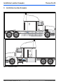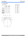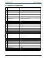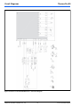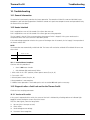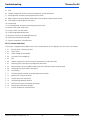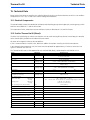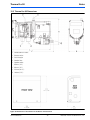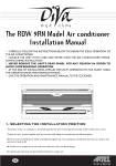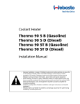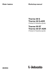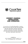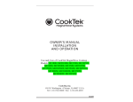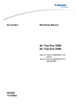
1
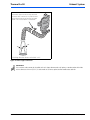
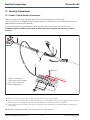
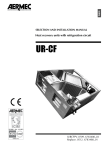
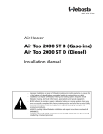
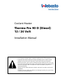
Coolant Heater Thermo Pro 90 D (Diesel) 12 / 24 Volt Installation Manual – Improper installation or repair of Webasto heating and cooling systems can cause fire or the leakage of deadly carbon monoxide leading to serious injury or death. – Installation and repair of Webasto heating and cooling systems requires special Webasto training, technical information, special tools and special equipment. – NEVER attempt to install or repair a Webasto heating or cooling system unless you have successfully completed the factory training course and have the technical skills, technical information, tools and equipment required to properly complete the necessary procedures. – ALWAYS carefully follow Webasto installation and repair instructions and heed all WARNINGS. – Webasto rejects any liability for problems and damage caused by the system being installed by untrained personnel. Thermo Pro 90 Table of Contents Contents Page 1. Safety and General Information 1.1 1.2 5 Warning Symbols in this Installation Manual . . . . . . . . . . . . . . . . . . . . . . . . . . . . . . . . . . . . . . . . . . . . . . . . . . . . . . . 5 General Information . . . . . . . . . . . . . . . . . . . . . . . . . . . . . . . . . . . . . . . . . . . . . . . . . . . . . . . . . . . . . . . . . . . . . . . . . 5 2. Regulation for Installation in the Vehicle 6 2.1 2.2 2.3 2.4 2.5 2.6 Scope . . . . . . . . . . . . . . . . . . . . . . . . . . . . . . . . . . . . . . . . . . . . . . . . . . . . . . . . . . . . . . . . . . . . . . . . . . . . . . . . . . . . 6 Fuel Supply . . . . . . . . . . . . . . . . . . . . . . . . . . . . . . . . . . . . . . . . . . . . . . . . . . . . . . . . . . . . . . . . . . . . . . . . . . . . . . . . 6 Exhaust System . . . . . . . . . . . . . . . . . . . . . . . . . . . . . . . . . . . . . . . . . . . . . . . . . . . . . . . . . . . . . . . . . . . . . . . . . . . . . 6 Combustion Air Inlet . . . . . . . . . . . . . . . . . . . . . . . . . . . . . . . . . . . . . . . . . . . . . . . . . . . . . . . . . . . . . . . . . . . . . . . . . 6 Water Inlet . . . . . . . . . . . . . . . . . . . . . . . . . . . . . . . . . . . . . . . . . . . . . . . . . . . . . . . . . . . . . . . . . . . . . . . . . . . . . . . . . 6 Hot Water Outlet . . . . . . . . . . . . . . . . . . . . . . . . . . . . . . . . . . . . . . . . . . . . . . . . . . . . . . . . . . . . . . . . . . . . . . . . . . . . 6 3. Purpose / Version 3.1 3.2 8 Purpose of the Coolant Heater . . . . . . . . . . . . . . . . . . . . . . . . . . . . . . . . . . . . . . . . . . . . . . . . . . . . . . . . . . . . . . . . . . 8 Versions . . . . . . . . . . . . . . . . . . . . . . . . . . . . . . . . . . . . . . . . . . . . . . . . . . . . . . . . . . . . . . . . . . . . . . . . . . . . . . . . . . . 8 4. Installation 4.1 4.2 4.3 4.4 4.5 9 Installation site / Installation position . . . . . . . . . . . . . . . . . . . . . . . . . . . . . . . . . . . . . . . . . . . . . . . . . . . . . . . . . . . . . 9 To install the heater . . . . . . . . . . . . . . . . . . . . . . . . . . . . . . . . . . . . . . . . . . . . . . . . . . . . . . . . . . . . . . . . . . . . . . . . . . 9 Model plate . . . . . . . . . . . . . . . . . . . . . . . . . . . . . . . . . . . . . . . . . . . . . . . . . . . . . . . . . . . . . . . . . . . . . . . . . . . . . . . . 9 CE mark . . . . . . . . . . . . . . . . . . . . . . . . . . . . . . . . . . . . . . . . . . . . . . . . . . . . . . . . . . . . . . . . . . . . . . . . . . . . . . . . . . 9 Compatibility . . . . . . . . . . . . . . . . . . . . . . . . . . . . . . . . . . . . . . . . . . . . . . . . . . . . . . . . . . . . . . . . . . . . . . . . . . . . . . . 9 5. Installation Location Examples 10 6. Mounting the Heater to the Vehicle 11 6.1 Allowable Mounting Positions . . . . . . . . . . . . . . . . . . . . . . . . . . . . . . . . . . . . . . . . . . . . . . . . . . . . . . . . . . . . . . . . . 11 7. Connection to the Vehicle Cooling System 7.1 7.2 14 General Information . . . . . . . . . . . . . . . . . . . . . . . . . . . . . . . . . . . . . . . . . . . . . . . . . . . . . . . . . . . . . . . . . . . . . . . . 14 Various Plumbing Configurations . . . . . . . . . . . . . . . . . . . . . . . . . . . . . . . . . . . . . . . . . . . . . . . . . . . . . . . . . . . . . . . 15 8. Fuel Supply 8.1 8.2 8.3 8.4 8.5 18 General Information . . . . . . . . . . . . . . . . . . . . . . . . . . . . . . . . . . . . . . . . . . . . . . . . . . . . . . . . . . . . . . . . . . . . . . . . 18 Fuel Standpipe Installation . . . . . . . . . . . . . . . . . . . . . . . . . . . . . . . . . . . . . . . . . . . . . . . . . . . . . . . . . . . . . . . . . . . . 19 Fuel Lines . . . . . . . . . . . . . . . . . . . . . . . . . . . . . . . . . . . . . . . . . . . . . . . . . . . . . . . . . . . . . . . . . . . . . . . . . . . . . . . . . 21 Fuel Metering Pump . . . . . . . . . . . . . . . . . . . . . . . . . . . . . . . . . . . . . . . . . . . . . . . . . . . . . . . . . . . . . . . . . . . . . . . . 21 Fuel Filter . . . . . . . . . . . . . . . . . . . . . . . . . . . . . . . . . . . . . . . . . . . . . . . . . . . . . . . . . . . . . . . . . . . . . . . . . . . . . . . . . 22 9. Combustion Air Supply 23 10.Exhaust System 24 11.Electrical Connections 26 11.1 11.2 11.3 11.4 Power / Control Harness Connections . . . . . . . . . . . . . . . . . . . . . . . . . . . . . . . . . . . . . . . . . . . . . . . . . . . . . . . . . . . 26 Connecting the Controls . . . . . . . . . . . . . . . . . . . . . . . . . . . . . . . . . . . . . . . . . . . . . . . . . . . . . . . . . . . . . . . . . . . . . 27 Vehicle Fan . . . . . . . . . . . . . . . . . . . . . . . . . . . . . . . . . . . . . . . . . . . . . . . . . . . . . . . . . . . . . . . . . . . . . . . . . . . . . . . 29 Setting Control Temperatures of Thermo Pro 90 . . . . . . . . . . . . . . . . . . . . . . . . . . . . . . . . . . . . . . . . . . . . . . . . . . . . 29 12.Circuit Diagrams 30 12.1 Thermo Pro 90 Circuit Diagram Legend . . . . . . . . . . . . . . . . . . . . . . . . . . . . . . . . . . . . . . . . . . . . . . . . . . . . . . . . . . 31 12.2 Thermo Pro 90 with ON/OFF Switch . . . . . . . . . . . . . . . . . . . . . . . . . . . . . . . . . . . . . . . . . . . . . . . . . . . . . . . . . . . . . 32 12.3 Thermo Pro 90 with 7-day SmarTemp Control fx Timer . . . . . . . . . . . . . . . . . . . . . . . . . . . . . . . . . . . . . . . . . . . . . . . 33 13.Initial Start-up 34 14.Troubleshooting 35 14.1 General Information . . . . . . . . . . . . . . . . . . . . . . . . . . . . . . . . . . . . . . . . . . . . . . . . . . . . . . . . . . . . . . . . . . . . . . . . 35 www.webasto.us 3 Webasto Thermo & Comfort N.A., Inc. Table of Contents Thermo Pro 90 14.2 Heater Interlock . . . . . . . . . . . . . . . . . . . . . . . . . . . . . . . . . . . . . . . . . . . . . . . . . . . . . . . . . . . . . . . . . . . . . . . . . . . .35 14.2.1 Interlock Reset Procedure . . . . . . . . . . . . . . . . . . . . . . . . . . . . . . . . . . . . . . . . . . . . . . . . . . . . . . . . . . . . . . .35 14.3 Diagnostic after a Fault Lock-out for the Thermo Pro 90 . . . . . . . . . . . . . . . . . . . . . . . . . . . . . . . . . . . . . . . . . . . . . .36 15.Technical Data 37 15.1 Electrical Components: . . . . . . . . . . . . . . . . . . . . . . . . . . . . . . . . . . . . . . . . . . . . . . . . . . . . . . . . . . . . . . . . . . . . . . .37 15.2 Fuel for Thermo Pro 90 (Diesel): . . . . . . . . . . . . . . . . . . . . . . . . . . . . . . . . . . . . . . . . . . . . . . . . . . . . . . . . . . . . . . . .37 15.3 Thermo Pro 90 Dimensions . . . . . . . . . . . . . . . . . . . . . . . . . . . . . . . . . . . . . . . . . . . . . . . . . . . . . . . . . . . . . . . . . . . .38 www.webasto.us 4 Webasto Thermo & Comfort N.A., Inc. Thermo Pro 90 Safety and General Information 1. Safety and General Information 1.1 Warning Symbols in this Installation Manual The purpose of safety symbols is to attract your attention to possible hazardous conditions. This manual uses a series of symbols and signal words which are intended to convey the level of importance of the safety messages. The progression of symbols is described below. Remember that safety messages by themselves do not eliminate danger and are not a substitute for proper accident prevention measures. DANGER WARNING CAUTION OR 1.2 Indicates an imminently hazardous situation which, if not avoided, WILL result in death or serious injury. Indicates a potentially hazardous situation which, if not avoided, COULD result in death or serious injury. Indicates a potentially hazardous situation which, if not avoided, MAY result in minor or moderate injury or property damage. It may also be used to alert against unsafe practices. These symbols are used to alert the installer to important or useful information about proper installation of the equipment. General Information Webasto Product North America, Inc. is pleased to provide this installation manual with the Thermo Pro 90 Heater. When used according to the guidelines stated in this manual, you can expect to provide years of trouble-free, enjoyable operation for your customer. This manual represents our latest effort to produce the best technical documentation possible. In our efforts towards continuous, ongoing product improvement, we encourage our customers to write to us with their comments or criticisms concerning this manual and the Thermo Pro 90 Heater Installation. Please write to us at: Webasto Thermo & Comfort North America, Inc. Technical Documentation Group 15083 North Road Fenton, MI 48430 You are also invited to fill out our online questionnaire concerning our technical documentation and web site at: www.techwebasto.com If you have any immediate questions concerning this manual, the installation procedures within or the product itself, please call us at: (800) 860-7866 www.webasto.us or send a fax to: (810) 593-6001 5 Webasto Thermo & Comfort N.A., Inc. Regulation for Installation in the Vehicle 2. Regulation for Installation in the Vehicle 2.3 2.1.1 2.1.2 2.2 Scope Subject to the provisions of paragraph 2.1.2, internal combustion heaters must be installed in accordance with the requirements contained in this Annex. The fuel filler neck must not be located in the passenger compartment and must have a tightly fitting cap to prevent any fuel leaks. 2.3.2 The type of fuel and the fuel filler neck must be clearly identified on heaters for liquid fuel, for which the fuel supply is separate from the fuel supply for the vehicle. 2.3.3 A sign must be affixed to the fuel filler neck warning that the heater must be switched off before refuelling. An identical warning must also be included in the manufacturer's operating instructions. In the case of vehicles and trailers with heaters for liquid fuel, it is presumed that these vehicles comply with the requirements in this Annex. 2.4 Position of the Heater 2.4.1 2.2.1 Parts of the vehicle body and other components in the immediate vicinity of the heater must be protected against excessive heat and the danger of contamination by fuel or oil. 2.2.2 The internal combustion heater must not pose a fire hazard even when overheated. This requirement is deemed to have been met if care is taken during installation to ensure an adequate distance from all parts, as well as adequate ventilation and if fire-resistant materials or heat shields are used. 2.2.3 2.2.4 2.2.5 2.2.6 2.5 For passenger carrying vehicles such as shuttle busses, transit busses, and coaches, the heater must not be installed in the passenger cabin. A device in a sealed cover, which also meets the requirements set out in paragraph 2.2.2, may be used, however. When positioning the heater, all reasonable precautions must be taken to minimize the risk of personal injury or damage to items in the vehicle. Webasto Thermo & Comfort N.A., Inc. Combustion Air Inlet 2.5.2 The air inlet must be positioned in such a way that it cannot be obstructed by other objects. Water Inlet 2.6.1 The supply of water to be heated must be protected against freezing with a suitable antifreeze additive to the required strength as directed by the manufacturer. The supply of water to be heated must be uncontaminated by corrosive compounds and other impurities. 2.6.2 The inlet hose must be protected from damage. 2.7.1 6 The exhaust outlet must be positioned in such a way that exhaust fumes cannot enter the interior of the vehicle through ventilation devices, hot-air inlets or open windows. The air for the combustion chamber of the heater must not be extracted from the passenger cabin of the vehicle. 2.7 A clearly visible indicator within the user's field of vision must show when the heater is switched on or off. Exhaust System 2.5.1 2.6 The model/ Serial plate or a duplicate thereof (duplicate model/ Serial plate) must be fitted in such a way that it is still clearly legible when the heater has been installed in the vehicle. Fuel Supply 2.3.1 Read this installation manual in its entirety before installing this equipment. 2.1 Thermo Pro 90 Hot Water Outlet Hot water hoses within the vehicle must be positioned or protected in such a way as to exclude all risk of injury or damage caused by direct contact. www.techwebasto.com Thermo Pro 90 2.7.2 Regulation for Installation in the Vehicle The water outlet hose must be protected so that it cannot be obstructed by other objects or the flow of water through the hoses. IMPORTANT! Failure to follow the installation instructions and the notes contained therein will lead to all liability being refused by Webasto. The same applies if repairs are carried out incorrectly or with the use of parts other than genuine Webasto service parts. This will result in the invalidation of the type approval for the heater and therefore of its homologation / type licence. www.webasto.us 7 Webasto Thermo & Comfort N.A., Inc. Purpose / Version Thermo Pro 90 3. Purpose / Version 3.1 Purpose of the Coolant Heater The Webasto Thermo Pro 90 coolant heaters are used in connection with the vehicle’s own heating system – – – – to heat the cab, to defrost vehicle windows and to preheat water-cooled engines, to heat boats and motor-homes (recreational vehicles) The water heater operates independently of the engine and is connected to the cooling system, the fuel system and the electrical system of the vehicle. The Thermo Pro 90 heaters differ from each other in their component connection arrangement and in the fact that they have different control units. 3.2 3.2.1 Versions Thermo Pro 90 version Thermo Pro 90 12V / 24V diesel Water heater for “diesel” fuel The water heaters are designed for 12 V and 24 volts. Webasto Thermo & Comfort N.A., Inc. 8 www.techwebasto.com Thermo Pro 90 Installation 4. Installation IMPORTANT! exhaust temperature sensor and the loose routing of the exhaust temperature sensor cable to the control unit must be ensured during installation. The water heater must be installed outside the passenger cabin. 4.3 The requirements of the latest version of “Hazmat” must also be observed for the installation of the heater into vehicles used to transport hazardous substances. 4.1 Model plate The model plate must be positioned so that it cannot be damaged and must be clearly legible when the heater is installed (otherwise a duplicate model plate must be used). Inapplicable years must be erased from the model plate. Installation site / Installation position 4.4 The heater must be installed in as low a position as possible to allow the heater and circulating pump to be bled automatically. This is particularly important as the circulating pump is not self-priming. CE mark The Thermo Pro water heater carries the CE mark since it complies with the regulations in force. The heater satisfies the requirements of class A. As a result, the following supplement applies: The installation must be performed in accordance with the installation instructions provided in this manual. This is a class A device. This device WARNING may induce radio interference in NOTE: If the vehicle manufacturer has issued specific installation instructions, they must be followed. 4.2 residential areas; in this case, the owner may be required to undertake appropriate measures. To install the heater As a rule, installation in the engine compartment represents sufficient screening. Please contact the Webasto technical support team in the event that radio interference occurs nevertheless. The heater must be secured with at least three M8 screws. The screws must be tightened with a torque of 18 Nm. (13.3 lb-ft). 4.2.1 Exhaust Temperature Sensor 4.5 The exhaust-temperature sensor cable is designed for high temperature (heat - resistant). The material is resistant to continuous effects of temperatures of up to 185 °C, however it is sensitive to external mechanical influences. Before the final installation location has been set, it is recommended conduct an analysis for the possible risk of damage to the cable due to stone impact. If stone impact is possible then precautionary measures must be taken. e.g. protective covering. Compatibility The heater is reverse compatibly with previous models regarding installation points on the vehicle. The peripherals of the Thermo Pro 90 are also compatible with the previous model Thermo 90 ST. This makes it possible to retrofit a Thermo Pro 90. The exhaust temperature sensor must be handled carefully - it is a sensitive electronic ceramic component! When the Thermo 90 ST is replaced with a Thermo Pro 90, the metering pump of the Thermo 90 ST (DP2 or DP30) must also be replaced with the Thermo Pro 90 metering pump (DP42)! Tensile loading of the exhaust temperature sensor cable on the sensor head must always be avoided during installation and heater operation. Sharp bends in the cable at the sensor head are not permitted in order to prevent damage to the Teflon insulation of the cable. When the metering pump is replaced (from DP2 or DP30 to DP42), a new metering pump wiring harness must be used for connecting the DP42 to the existing Thermo 90 ST wiring harness (5m metering pump harness 5010871A). Do not pull on the cable after the exhaust temperature sensor is installed! Should a sensor be dropped during maintenance work, then a new sensor must be installed. The proper condition of the mica disc (insulation) on the sensor, the force-free seating of the cable clips of the www.webasto.us 9 Webasto Thermo & Comfort N.A., Inc. Installation Location Examples Thermo Pro 90 5. Installation Location Examples Figure 1: Installation locations Webasto Thermo & Comfort N.A., Inc. 10 www.techwebasto.com Thermo Pro 90 Mounting the Heater to the Vehicle 6. Mounting the Heater to the Vehicle 6.1 Allowable Mounting Positions 3 1 2 Coolant Direction Fuel Connection Figure 2: Allowable enclosure kit mounting positions, 1 and 2 only. Position 3 is not permissible. Figure 3: Permitted installation positions for the Thermo Pro 90 heaters 1 - Fuel inlet 2 - Heat exchanger outlet 3 - Heat exchanger inlet 4 - Exhaust outlet 5 - Combustion air inlet A - Height 232mm (9.13”) B - Width 140mm (5.5”) L - Length 355mm (14”) L* - Length from control unit to inlet connection piece of circulation pump Figure 4: Thermo Pro 90 heater Inlets / Outlets / Dimensions www.webasto.us 11 381mm (15”) Webasto Thermo & Comfort N.A., Inc. Mounting the Heater to the Vehicle Thermo Pro 90 Do not drill holes through top or bottom of vehicle frame flanges! CAUTION Do not weld vehicle frame or flanges! mm ) 80 /32” 5 (3mm ) 70 3/4” (2- Figure 5: Drill frame within the shaded area only! 310mm (12-13/64”) 80mm (3-5/32”) 70mm (2-3/4”) 150mm (5-29/32”) 23mm (29/32”) 50mm (1 31/32”) Figure 6: Mounting heater enclosure via back wall (Vertical or horizontal mounting) Webasto Thermo & Comfort N.A., Inc. 12 www.techwebasto.com Thermo Pro 90 Mounting the Heater to the Vehicle 150mm 150mm 484mm 363mm 158mm 500mm Figure 7: Optional perpendicular mounting with bracket kit P/N 905838 www.webasto.us 13 Webasto Thermo & Comfort N.A., Inc. Connection to the Vehicle Cooling System Thermo Pro 90 7. Connection to the Vehicle Cooling System 7.1 General Information The heater is connected to the vehicle cooling system as shown in Figures 9 through 14, depending on the type of heating system the vehicle is equipped with. The system must contain at least 6 litres (1.6 US Gal.) of coolant. The system must be filled with an antifreeze and water mixture as recommended by the vehicle manufacturer. Coolant flow throughout the system must be maintained in all operating conditions. If desired, shut-off valves can be installed at the engine inlet and outlet connections of the coolant heater circuit, although, shut-off valves are not mandatory. All valves should remain open throughout the year. IMPORTANT! To maintain optimum heater condition, periodically run heater for 20 minutes monthly during the off-season. Ensure any shut-off valves are open before operating the coolant heater. • Use 1/2” or larger NPT pipe fittings for hose connections at engine. • Use good quality, heavy duty 3/4” ID. coolant hose for the coolant heater circuit. • Hoses must be installed without kinks and bends which may restrict coolant flow. • To ensure proper bleeding of air, keep hoses rising if possible. Avoid “goose necks” to prevent trapping air. • Hoses must be supported where required to prevent chaffing and damage from vehicle components. • Hose connections must be secured by hose clamps to prevent them from slipping off. • Coolant heater flow direction should match the flow direction of the engine’s coolant circulation system. IMPORTANT! The hose clamps must be tightened with a torque of 4 Nm. (35 lb.-in.) The use of silicone hose requires special hose clamps. Separate the heater supply and return connections at the engine as far apart as is practical for optimum engine heating and heater performance. See Figure 8. Optimum Cross-Flow Through Engine Figure 8: Ensure optimum cross-flow Webasto Thermo & Comfort N.A., Inc. 14 www.techwebasto.com Thermo Pro 90 Connection to the Vehicle Cooling System The cooling system must be bled carefully before using the heater for the first time or after replacing the coolant. Proper venting of trapped air can be identified by the circulating pump operating almost silently. Poor bleeding may cause the resetting temperature limiter to trip while the heater is in operation. 7.2 Various Plumbing Configurations Select the appropriate plumbing configuration according to the customers requirements and the vehicle system type. Figure 9 illustrates an engine preheat / boost heat configuration. Figures 10 through 13 illustrate configurations for bunk heat and engine preheat / boost heat. Figure 14 illustrates a system for vehicles with continuous fan operation or high amperage heat exchanger fan designs. In this case, the addition of a low amperage draw, auxiliary heat exchanger system is recommended. 2 7 1. 2. 3. 4. 5. 6. 7. Coolant supply connection Vehicle heat exchanger Coolant pump Thermo Pro 90 heater Coolant return connection Engine coolant pump Thermostat 1. 2. 3. 4. 5. 6. 7. Coolant supply connection Vehicle heat exchangers Coolant pump Thermo Pro 90 heater Coolant return connection Engine coolant pump Thermostat 1 6 4 5 3 Figure 9: System configured for engine pre-heating and boost heating. 2 2 1 7 6 4 5 3 Figure 10: System configured in a “series” fashion with both heat exchangers. www.webasto.us 15 Webasto Thermo & Comfort N.A., Inc. Connection to the Vehicle Cooling System 2 Thermo Pro 90 2 7 1 1. 2. 3. 4. 5. 6. 7. Coolant supply connection Vehicle heat exchangers Coolant pump Thermo Pro 90 heater Coolant return connection Engine coolant pump Thermostat 6 4 5 3 Figure 11: System configured in series with rear heat exchanger in a “dual” circuit heating system. 2 2 7 1 1. 2. 3. 4. 5. 6. 7. Coolant supply connection Vehicle heat exchangers Coolant pump Thermo Pro 90 heater Coolant return connection Engine coolant pump Thermostat 4-way back-check valve 6 4 5 3 Figure 12: System configured in the rear heat exchanger circuit using an optional 4-way back-check valve. 2 2 8 7 10 9 1 9 6 1. 2. 3. 4. 5. 6. 7. 8. 9. 10. Coolant supply connection Vehicle heat exchangers Coolant pump Thermo Pro 90 heater Coolant return connection Engine coolant pump Thermostat Automated control valve Wye connectors Bypass hose 13-16mm I.D. (1/2”- 5/8” I.D.) 4 5 3 Figure 13: System configured with a bypass circuit within the rear heat exchanger circuit where an automated flow control valve is installed. Bypass is required in the event the valve is closed during heater operation. Webasto Thermo & Comfort N.A., Inc. 16 www.techwebasto.com Thermo Pro 90 11 Connection to the Vehicle Cooling System 2 2 8 7 9 1 9 6 4 1. 2. 3. 4. 5. 6. 7. 8. 9. 10. 11. Coolant supply connection Vehicle heat exchangers Coolant pump Thermo Pro 90 heater Coolant return connection Engine coolant pump Thermostat Automated control valve Wye connectors N/A Auxiliary heat exchanger 5 3 Figure 14: System configured with an additional auxiliary heat exchanger connected in “series / parallel” with rear heat exchanger circuit. www.webasto.us 17 Webasto Thermo & Comfort N.A., Inc. Fuel Supply Thermo Pro 90 8. Fuel Supply 8.1 General Information The values for the maximum pressure at the fuel extraction point are shown in the table below and in Figure 16. Intake Side Pressure Side D1- Inside diameter of fuel line = 2 mm. D2: Inside diameter of fuel line = 2 mm. H1 - Dimension for fuel tank over metering pump [m] H2: Dimension for heater over metering pump [m] S1 - Dimension for fuel tank under metering pump [m] S2: Dimension for heater under metering pump [m] l1 - Length of fuel line l2: Length of fuel line with D1 = 2 mm => l1 ≤ 3 m P1: Relative fuel pressure at removal point The fuel is taken from the vehicle fuel tank or from a separate fuel tank. The exploded view in Figure 15 Illustrates the progression of fuel system components. Figure 16: Fuel system parameters A sign must be affixed to the fuel tank’s filler neck warning that the heater must be switched off before refuelling. Figure 15: Fuel system components B F A E G D 0° C A. B. C. D. Fuel standpipe Connector hose Fuel filter Hose clamp Webasto Thermo & Comfort N.A., Inc. E. Fuel pump F. Fuel line G. 90° Connector hose 18 www.techwebasto.com Thermo Pro 90 8.2 Fuel Supply Fuel Standpipe Installation To install the standpipe: This separate fuel pickup precludes any effect of pressure. 1. bore a 25mm (1”) hole through top of fuel tank (item G, Figure 17). 2. remove sharp burrs and smooth edges with emery cloth. 3. determine length of standpipe when installed. End should sit at least 25mm (1”) above tank bottom. Cut off excess standpipe at a 45 degree angle. Remove burrs. 4. loosely assemble items C, D, E, and F (Figure 17). 5. place sealing compound on threads of item B and thread into item F. Tighten item B completely. 6. slide standpipe into hole at angle. Slip one shoulder of item F, Figure 17 inside the hole as shown in Figure 18. Where available, a spare NPT threaded port can be utilized for the standpipe. If a spare port is not present, proceed with the following instructions under “To install the standpipe”. A B Ø 25mm (1”) C D E F Fuel Tank 25mm (1”) Ø 25mm (1”) F G Detail View A. B. C. D. E. F. G. Fuel standpipe Compression fitting Hex nut Metal washer Rubber washer Tank boss 1/4” NPT 25mm (1”) hole Figure 18: Standpipe installation - illustration 1 Figure 17: Webasto fuel standpipe www.webasto.us 19 Webasto Thermo & Comfort N.A., Inc. Fuel Supply Thermo Pro 90 7. bring standpipe up to horizontal and insert opposite shoulder under the tank hole. See Figure 19. 8. center standpipe in tank hole. See Figure 20. Figure 20: Standpipe installation - illustration 3 9. pull up on standpipe and tighten in place with the clamping nut (item A in Figure 21). Do not overtighten causing rubber washer to squeeze out! A Figure 19: Standpipe installation - illustration 2 Fuel Tank Figure 21: Standpipe installation - illustration 3 Webasto Thermo & Comfort N.A., Inc. 20 www.techwebasto.com Thermo Pro 90 8.3 Fuel Supply Fuel Lines Only steel and plastic lines made of plasticized, light and temperature-stabilized may be used for the fuel lines. Since the lines normally cannot be routed with a constant rising gradient, the internal diameter must not be allowed to exceed a certain size. Air or gas bubbles will accumulate in lines with an internal diameter of more than 4 mm (5/32 in.) and these will cause malfunctions whilst the heater is operating if the lines sag or are routed downwards. The diameters specified in Figure 16 will ensure that bubbles do not form. The lines should not be routed downwards from the metering pump to the heater. Unsupported fuel lines must be secured to prevent them from sagging. They must be installed in such a way that they cannot be damaged by flying road debris and high temperatures, i.e. close to the exhaust line. Figure 23: Fuel line / coupler hose connection The fuel lines must be secure at the connections using hose clips to prevent their slipping. 8.4 The fuel metering pump is a combined delivery, metering and shut-off system and is subject to certain installation criteria (see Figures 24). IMPORTANT! Cut lines without burr and do not crush them. Do not cut fuel line with side cutting pliers! 8.3.1 Fuel Metering Pump Connecting two fuel lines with a coupler hose The correct procedure for connecting fuel lines with hosing is shown in Figure 22. Ensure that there are no leaks. Correct Clamp Figure 24: Metering pump DP42 - installation position 8.4.1 Installation Location It is advisable to install the metering pump in a cool place. Wrong Bubble Bubble The metering pump and fuel lines must not be installed within range of the radiated heat from hot vehicle parts. A heat shield must be used if necessary. Figure 22: Fuel line / coupler hose connection www.webasto.us 21 Webasto Thermo & Comfort N.A., Inc. Fuel Supply 8.4.2 Thermo Pro 90 Attachment The metering pump must be secured with a vibrationdamping mounting. Its installation position is limited as shown in Figure 24 in order to ensure effective automatic bleeding. As a result of the risk of corrosion, only genuine Webasto parts may be used for the plug connections between the metering pump and the metering pump wiring harness. 8.5 Fuel Filter Only a Webasto filter is allowed to be used if the fuel is expected to be contaminated. Install vertically if possible, however at least horizontally (check flow direction). IMPORTANT! Do not substitute the Webasto supplied fuel filter with a non Webasto replacement. Irregular heater operation may result. 0° - 90° A Ø 5mm Figure 25: Fuel filter Webasto Thermo & Comfort N.A., Inc. 22 www.techwebasto.com Thermo Pro 90 Combustion Air Supply 9. Combustion Air Supply Under no circumstances may the combustion air be taken from areas occupied by people. The combustion air intake opening must not point in the direction of travel. It must be located in that it cannot become clogged with dirt or snow and cannot suck in splashing water. IMPORTANT! The combustion air must be extracted using a combustion air tube from a position that is as cool as possible and protected from splashing water. The combustion air intake tube (internal diameter at least 30 mm) may be 0.5 m to 5 m (1.6 ft to 16 ft) long with several bends totalling 360°. The minimum bending radius is 45 mm (1.75 inches). The combustion air intake must not be routed in the vicinity of the exhaust discharge. IMPORTANT! A minimum of 0.5m of the combustion air tube must be installed on every application. IMPORTANT! If the combustion air intake tube cannot be installed so that it slopes downwards, a water drain hole with a diameter of 4 mm (5/32”) is to be made at its lowest point. If the heater is installed in the vicinity of a fuel source, the combustion air tube must be routed in a way to prevent fumes from entering. The openings must be splashproof. A ventilation opening measuring at least 7 cm² is required if the heater is installed in an enclosed box. The size of the ventilation opening must be increased accordingly if the temperature in the box exceeds the permitted ambient temperature of the heater (see Technical data). www.webasto.us 23 Webasto Thermo & Comfort N.A., Inc. Exhaust System Thermo Pro 90 10. Exhaust System The exhaust pipe (internal diameter 38 mm) can be installed with a length of 0.5 m to 5 m (1.6 ft to 16 ft) and several bends totalling a maximum of 360° altogether. The minimum bending radius is 85 mm (3.35 inches). The exhaust muffler is required and must be installed near the heater. The opening of the exhaust pipe must not point towards the front of the vehicle (see Figure 27). The exhaust pipe opening must be located so that it cannot become clogged with snow and mud. Rigid pipes of unalloyed or alloyed steel with a minimum wall thickness of 1.0 mm or flexible piping of alloyed steel only must be used as exhaust tube. The exhaust pipe is secured to the muffler using an approved muffler clamp. See Figure 27 for details. See the regulations section 2 for other requirements. Heater removed for clarity of illustration B C A Figure 26: Exhaust muffler installation - enclosure kit only A. Muffler B. coupler (between heater and muffler) C. “L” bracket The exhaust muffler is secured to the heater using a coupler between the heater and muffler and a bracket fastened to the underside of the enclosure. See Figure 26 for details. Webasto Thermo & Comfort N.A., Inc. 24 www.techwebasto.com Thermo Pro 90 Exhaust System The exhaust pipe must be securely attached no further than 150 mm (6 in.) from the end of the exhaust pipe to ensure that the angle of 90° ± 10° vertical-down is maintained. 10° 10° Discharge direction almost vertical 90° ± 10° Figure 27: Exhaust pipe termination IMPORTANT! If the exhaust tube cannot be installed so that it slopes downwards at all points, a condensation drain hole with a diameter of 4 mm (5/32”) is to be made at its lowest point to allow condensate to drain. www.webasto.us 25 Webasto Thermo & Comfort N.A., Inc. Electrical Connections Thermo Pro 90 11. Electrical Connections 11.1 Power / Control Harness Connections Ideally, the heater power supply should be directly from the vehicle’s batteries or main buss-bar. The heater control unit is equipped with low voltage protection. It is imperative that the vehicle batteries be kept in good condition for optimal heater operation. For sleeper and engine heating applications, Webasto recommends a four battery system for best results. A weather sealed fuse holder is to be fitted to protect the heater (supplied with the power / control harness). 1 2 3 To H ea 4 ter Con t ro l Uni t Main Fuse + Veh ic + 1. 2. 3. 4. Switch / Timer Harness Heater Harness (Pre-installed) Main Harness Connector Power Supply Harness + + – le S ys tem Pow er – – – Fram eG ro und Figure 28: Power and control harness assembly A. Route item 1 into the vehicle cab in the area where the switch or timer is to be installed. B. Route item 4 to vehicle battery box and connect to batteries as shown in Figure 28. Brown wire to ground, red wire with fuse holder to positive. Ensure battery connections are clean and protected with an anti-corrosive compound. C. Item 3 (main connector) should be left unconnected until all electrical components are installed and heater is ready for the initial start-up. IMPORTANT! All power connections must be fused within 14” of the battery. Webasto Thermo & Comfort N.A., Inc. 26 www.techwebasto.com Thermo Pro 90 Electrical Connections 11.2 Connecting the Controls The heater can be switched on and off using the following Webasto controls: • Switch, see circuit diagrams in Figures 29 and 33. • Timer, see circuit diagrams in Figures 30 and 34. 11.2.1 Toggle Switch 1 2 3 4 Heater Control Harness Connection Using a 24 Volt Switch 1. 2. 3. 4. White (Ground) Red (Power) Black (On signal) Green (Operation indication) Figure 29: Toggle switch 11.2.2 Control Element (SmarTemp) Timer Connection Heater Control Harness Connection Using SmarTemp Control fx 1. 2. 3. 4. Red (Power) Brown (Ground) Black or Grey (ON/OFF Signal) Green (Diagnostic Blink Code) Figure 30: 7-Day, 4 Program SmarTemp Control fx Timer All the cables and wires that are not required must be insulated against accidental CAUTION shorting or grounding. www.webasto.us 27 Webasto Thermo & Comfort N.A., Inc. Electrical Connections Thermo Pro 90 The Control Panel should be installed in a suitable location on a flat surface if possible in a visible area. – Connect control panel to existing connectors on heater-unit wiring harness (see “Connections Diagrams Section”) – Use the drilling dimensions (fig. 32) to lightly mark the two mounting holes. – (Optional Step) To route wire harness through the mounting surface, drill a 17mm (11/16”) hole. Make sure to push harness through the hole before installing terminals into connector housing) – Secure the SmarTemp Control using the two supplied #4 screws. – Apply the supplied “Heater Off” warning sticker in a highly visible location to the drivers area. – Observe the installation / operating manual supplied for proper menu setup. Figure 31. Control element (SmarTemp Control fx) NOTES: – Always make sure there are no obstacles behind the mounting location prior to drilling. – Ensure good readability when selecting installation location. – Observe information on adhesive labels and colored markings when connecting the control element to vehicles wiring harness. Figure 32. SmarTemp drilling dimensions Webasto Thermo & Comfort N.A., Inc. 28 www.techwebasto.com Thermo Pro 90 Electrical Connections 11.3 Vehicle Fan The vehicle's own heater fan can be controlled using a relay, see circuit diagram Figs. 33 or 34 (connecter X8 contact 2 Violet or contact D of X13. 11.4 Setting Control Temperatures of Thermo Pro 90 When the ignition signal is connected to the control unit connector X8, contact 7, different control thresholds are effective. Nominal Temperature on Sensor Regulation Temperature Switch on Again After Regulation Temperature Engine “ON” 65°C (149°F) 75°C (167°F) 60°C (140°F) Engine “OFF” 80°C (176°F) 90°C (194°F) 75°C (167°F) If the terminal D+ signal is not applied, the temperatures are the same as those at “Engine off”. www.webasto.us 29 Webasto Thermo & Comfort N.A., Inc. Circuit Diagrams Thermo Pro 90 12. Circuit Diagrams Cable Cross Sections Webasto Thermo & Comfort N.A., Inc. Cable Colors Legend 30 www.techwebasto.com Thermo Pro 90 Circuit Diagrams 12.1 Thermo Pro 90 Circuit Diagram Legend Item Designation Comment A1 Heater A2 Control module B1 Exhaust Temperature sensor B2 Coolant temperature sensor B3 Temperature limiter/ overheat sensor BT Battery H1 Operation indicator light 1 Vehicle blower circuit E Glow plug F1 Fuse 5 A ATM mini flat fuse F2 Fuse 20 A ATM mini flat fuse F3 Fuse 30 A ATO flat fuse H1 “Heating” symbol in the display Operating indicator (in item P2) H3 Symbol light Light (in item P2) M1 Motor Combustion air fan M2 Motor Circulating pump P1 SmarTemp fx For programmed operation P2 Digital timer 1531 For programmed operation S1 Toggle switch ON/OFF X1 4-pin plug connector To item M1 (Combustion air fan motor) X2 Plug connector, 2-pin To item E (igniter) X3 Plug connector, 2-pin To connector X11 (Fuel pump) X4 Plug connector, 2-pin To connector X12 (Circulating pump) X5 Plug connector, 2-pin To item B2 (Coolant temperature sensor) X6 Plug connector, 2-pin To item B1 (Exhaust temperature sensor) X7 Plug connector, 2-pin To item B3 (Temperature limiter) X8 12-pin plug connection To item A1 (Control unit) X10 Plug connector, 2-pin Diagnostics X11 Plug connector, 2-pin To item Y1 (Fuel pump) X12 Plug connector, 2-pin To item M2 (Circulating pump) X13 Plug connector, 9-pin To item X14 X14 Plug connector, 9-pin To item S1 or P1 X15 Plug connector, 4-pin To item X16 X16 Plug connector, 4-pin To item P1 Y1 Metering pump Fuel pump for heater www.webasto.us Vehicle battery Terminal needs to be added to X14 Webasto P/N: 901204 Deutsch P/N:0462-209-16141 31 Webasto Thermo & Comfort N.A., Inc. Circuit Diagrams Thermo Pro 90 Figure 33: Thermo Pro 90 with ON/OFF Switch - Connection Diagram Webasto Thermo & Comfort N.A., Inc. 32 www.techwebasto.com Thermo Pro 90 Circuit Diagrams Figure 34: Thermo Pro 90 with 7-day SmarTemp Control fx Timer - Connection Diagram www.webasto.us 33 Webasto Thermo & Comfort N.A., Inc. Initial Start-up Thermo Pro 90 13. Initial Start-up IMPORTANT! Refer to the safety instructions in the operating and maintenance instructions. The operating and maintenance instructions must be read thoroughly before starting the heater. NOTE: As a result of the low fuel consumption the heater may require several start attempts to fill the fuel line and prime the system. Before the heater is operated for the first time, the coolant temperature should be < 60 °C (140°F), as the heater does not go into combustion operation at high engine temperatures. After you have installed the heater, bleed the water system and the fuel supply system carefully. Follow the instructions supplied by the vehicle manufacturer for this purpose. Conduct a trial of the heater to check all the water and fuel connections for leaks and to ensure that they are secure. If the heater suffers a fault during operation, the fault must be located and remedied. Example: 11 sec. filling time with 1m line length, 9 Hz metering pump frequency, 2 mm inside diameter of fuel line. The CO2 setting is not necessary as part of initial start-up, as the heater has been preset at the factory. The detailed procedure for CO2 setting is described in the workshop manual. Webasto Thermo & Comfort N.A., Inc. 34 www.techwebasto.com Thermo Pro 90 Troubleshooting 14. Troubleshooting 14.1 General Information The control unit continuously monitors the heater operation. The control unit identifies errors on individual heater components and faults during operation. Should the control unit experience component errors and operational faults, the heater will be shut down. 14.2 Heater Interlock Fuel is supplied for a max. of 240 seconds if the flame does not start. Fuel is supplied for a max. of 240 seconds if the flame goes out during operation. The fuel supply is shut off if the system overheats (temperature limiter is tripped). If the system overheats the temperature limiter will reset itself after a cool down period. If the under-voltage protection switches the system off for longer than 20 seconds, the fuel supply is interrupted and the heater switches OFF. NOTE: The heater does not automatically switch back ON. The heater will need to be switched OFF and back ON to re-start after a fault. Thermo Pro 90 12 Volt 10.V – 0.5V 24 Volt 21V – 1V 14.2.1 Interlock Reset Procedure Continue with this procedure if: • there is NO heater function • fault indicator light continuously flashes 1. With switch in the “ON” position, remove power source (Fuse, B+, B-) 2. Turn switch “OFF” 3. Reinstall power source (Fuse, B+, B-) 4. Reset procedure is now complete. 5. Validate heater operation. If fault codes persist refer to section 14.3 and repair as necessary. 14.3 Diagnostic after a Fault Lock-out for the Thermo Pro 90 Check the fuses and plug connectors. 14.3.1 Version with switch If the system is operated with a switch, the nature of the fault is indicated by a flashing code on an indicator light (toggle of switch) during the run-on time of the heater. After five short signals, count the long flashes: 1x No start (after 2 attempts to start) 2x Flame failure 3x Under-voltage or over-voltage 4x Premature flame recognition www.webasto.us 35 Webasto Thermo & Comfort N.A., Inc. Troubleshooting Thermo Pro 90 5x N/A 6x Coolant temperature sensor interrupt or temperature sensor short-circuit 7x Metering pump interrupt or metering pump short-circuit 8x Blower motor interrupt or blower motor short-circuit or blower motor incorrect speed 9x Glow plug interrupt or igniter short-circuit 10x Overheating 11x Circulating pump interrupt or circulating pump short-circuit 12x Battery main switch short circuit 13x Output vehicle fan short circuit 14x Overheating protection defective 15x Reference resistance not reached during start 16x Exhaust gas temperature too high 17x Exhaust temperature sensor defective 14.3.2 Version with timer If the system is equipped with a digital timer, a fault message appears on the display of the timer after a fault occurs: F 01 No start (after 2 attempts to start) F 02 Flame failure F 03 Under-voltage or over-voltage F 04 Premature flame recognition F 05 N/A F 06 Coolant temperature sensor interrupt or temperature sensor short-circuit F 07 Metering pump interrupt or metering pump short-circuit F 08 Blower motor interrupt or blower motor short-circuit or blower motor incorrect speed F 09 Glow plug interrupt or igniter short-circuit F 10 Overheating F 11 Circulating pump interrupt or circulating pump short-circuit F 12 Battery main switch short circuit F 13 Output vehicle fan short circuit F 14 Overheating protection defective F 15 Reference resistance not reached during start F 16 Exhaust gas temperature too high F 17 Exhaust temperature sensor defective Webasto Thermo & Comfort N.A., Inc. 36 www.techwebasto.com Thermo Pro 90 Technical Data 15. Technical Data Except where limit values are specified, the technical data refer to the usual heater tolerances of ±10% at an ambient temperature of +20 °C (68 °F) and at the nominal voltage and conditions. 15.1 Electrical Components: The control module, motors for combustion air blower and circulating pump, ceramic glow pin, metering pump, switch and timer are available in 12 and 24 volt versions. The temperature limiter, temperature sensor and flame sensor are identical on 12V and 24V heaters. 15.2 Fuel for Thermo Pro 90 (Diesel): The diesel fuel specified by the vehicle manufacturer must be used. Heating oil may also be used as long as it complies to the normal quality available on the North American market. We know of no negative influences due to additives. If fuel is extracted from the vehicle’s tank, follow the additive instructions issued by the vehicle manufacturer. If you change to low-temperature fuel, the heater must be operated for approximately 15 minutes so that the fuel system is filled with the new fuel. The Thermo Pro 90 heater is also approved for use with PME (bio-diesel), which complies with DIN EN 14214. Heater Operation Thermo Pro 90 Approval symbol E1 122R 00 0320 (Heater) E1 10R 03 6196 (EMC) Model Water heater with evaporative-type burner Heat output Max. regulating range 9.1 kW (31,000 BTU) 1.8 kW – 7.6 kW (6,000 BTU/hr - 26,000 BTU/hr) Fuel Diesel PME (Bio-diesel) Fuel consumption Max. regulating range 1.1 l/h (.29 Gal/hr) > 0.21 – 0.92 l/h (0.05 Gal/hr - 0.24 Gal/hr) Rated voltage Operating voltage range Nominal power consumption with circulation pump (without vehicle fan) Perm. ambient temp.: Heater control Unit: Metering pump: 12 V 24 V 10.5... 15.5 V or 20 ... 31.5 V ≤ 90 W ≤ 80 W ≤ 37 W Max. regulating range - Operation -Storage -40° ... +80° C (- 40°... + 176°F) -40° .. +125 °C (- 40°.. +257°F) (heater off, operating voltage may be connected) - Operation -Storage > -40 +30 °C (> -40 +86°F) > -40 +85 °C (> -40 +185°F) Perm. operating pressure (heat medium) Max. 2.0 bar (29 PSI) Capacity of the heat exchanger 0.15 l (.158 quart) Max. combustion air intake temperature +40 °C (104°F) Minimum capacity of the system 6.00 l (6.34 quarts) CO2 in the exhaust gases (normal function range) Max. Heater dimensions (tolerance 3 mm) * Control module installed on the heater 9 ... 11.5% by volume L = Length: 355 (381*) mm W = Width: 131 mm H = Height: 232 mm Weight 4,9 kg (10.8 lbs.) U4840 Coolant Pump Volume Flow @ 0.3bar (4.35 PSI) 700 l/h (3.08 gal/min) Dimensions 134 x 53 x 90 (5.28” x 2.08” x 3.5”) Weight .36 kg (.8 lbs) Table 1: Technical Data www.webasto.us 37 Webasto Thermo & Comfort N.A., Inc. Thermo Pro 90 Notes 15.3 Thermo Pro 90 Dimensions 1 Combustion air intake 2 Exhaust outlet 3 Fuel inlet pipe 4 Coolant inlet 5 Coolant outlet L 355mm (14”) L* 381mm (15”) H 232mm (9.13”) B 140mm (5.5”) Figure 35: Dimensions of the Thermo Pro 90 Heater / Enclosure Box www.webasto.us 38 Webasto Thermo & Comfort N.A., Inc. Thermo Pro 90 Technical Data NOTES www.webasto.us 39 Webasto Thermo & Comfort N.A., Inc. Webasto Thermo & Comfort N.A., Inc. 15083 North Road Fenton, MI 48430 Technical Assistance Hotline USA: (800) 860-7866 Canada: (800) 667-8900 Org. 5/2014 Rev. 12/2014 P/N 5010926A www.techwebasto.com