1
ity
c t i v 490
e
n
C o n CDM
New 0 and
2
B4
CD
O P E R AT I N G I N S T R U C T I O N S
CLV490
Bar Code Scanner
Advanced Line
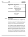
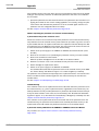
Software versions
Operating Instructions
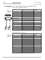
CLV490 Bar Code Scanner
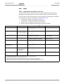
Software versions
Software/Tool
Function
Version
CLV490-0010/-0011
Firmware
V 5. O RA32
CLV490-1010/-1011
Firmware
V 5. O RA32
CLV490-6010/-6011
Firmware
V 5. O RA32
CLV490-7010/-7011
Firmware
V 5. O RA32
CLV490-2010/-2011
Firmware
V 5. O RA32
CLV490-3010/-3011
Firmware
V 5. O RA32
CLV-Setup
Configuration software (windows-based)
V 4. 4 QF16
CLV-Setup Help
Online help (HTML)
V 4. 4 QF16
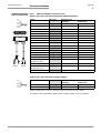
Copyright
Copyright © 2004 - 2007
SICK AG Waldkirch
Auto Ident, Reute Plant
Nimburger Strasse 11
79276 Reute
Germany
Trademarks
Windows 95TM/98TM, Windows NTTM, Windows 2000TM, Windows XPTM and Internet
ExplorerTM are registered trademarks or trademarks of the Microsoft Corporation in the USA
and other countries.
AcrobatTM ReaderTM is a trademark of the Adobe Systems Incorporated
Latest manual version
For the latest version of this manual (PDF), see www.sick.com.
I-2
© SICK AG · Division Auto Ident · Germany · All rights reserved
8009993/RA61/2007-07-20
Operating Instructions
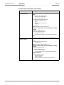
Quick Finder
CLV490 Bar Code Scanner
CLV490 Bar Code Scanner
Quick Finder
•
What is delivered with the device
– Chapter 3.1.1 Scope of delivery, Page 3-1
•
CAUTION!
– Chapter 2 Safety information, Page 2-1
•
Mounting the device at the reading station
– Chapter 4 Installation, Page 4-1
•
Connecting the device
– Chapter 5 Electrical installation, Page 5-1
•
Overview of the device and its functions
– Chapter 3 Product description, Page 3-1
– Chapter 6.2 Default settings, Page 6-1
– Chapter 6.5 Operating modes and outputing the reading result, Page 6-38
– Chapter 9 Technical data, Page 9-1
– Chapter 10.3 Installing and operating the external parameter memory (connector cover), Page 10-34
•
Starting the device with the default settings
– Chapter 6.3 Quick start, Page 6-3
•
Installing the "CLV-Setup" program
– Chapter 10.6 Installing and operating the "CLV-Setup" program, Page 10-43
•
Adapting the device to the reading application
– Chapter 6.4 Configuring (parameterization) the CLV490, Page 6-5
•
Troubleshooting
– Chapter 8 Troubleshooting, Page 8-1
•
Finding information
– Table of contents, Page I-5
– Index, Page 10 -95
8009993/RA61/2007-07-20
© SICK AG · Division Auto Ident · Germany · All rights reserved
I-3
Quick Finder
Operating Instructions
CLV490 Bar Code Scanner
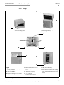
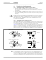
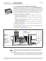
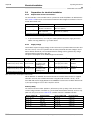
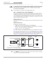
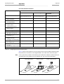
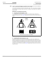
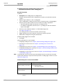
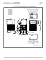
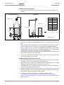
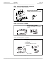
Installation procedure (overview)
CLV490 in stand-alone configuration (without heating)
Start/stop mode: Reading trigger via “Sensor“ switching input (default setting)
1.
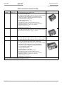
Check the delivery to make sure that none of the components is missing.
2.
Mount the CLV490 at the reading station/ align it with the object carrying the bar code.
3.
Mount the CDB420 or CDM490 Connection Module.
4.
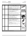
Connect the CLV490 as followed:
CDB420 Connection Module: using the cable no. 2027046. Alternatively, connect the
CLV490 using the external parameter memory no. 2030023.
CDM490 Connection Module: using two cables no. 2020302. Alternatively, connect
the CLV490 using the external parameter memory no. 2020307.
5.
Mount the sensor for starting/stopping the reading pulse.
6.
Connect the reading pulse sensor to the "Sensor (1)" input in the CDB420 or CDM490.
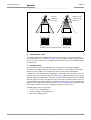
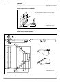
7.
Connect the host to the host interface in the CDB420 or CDM490.
8.
Switch on the power supply to the CDB420 or CDM490.
The "Device Ready" LED lights up after the CLV490 has started.
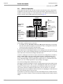
CLV490 with empty parameter memory connected (no. 2020307 or no. 2030023):
After the CLV490 has started, it copies the internal parameter set to the external parameter memory if no CMC400 parameter memory is available in the CDB420/
CDM490.
Line scanner with oscillating mirror:
In the default setting, the CLV490 deflects the scan line around the position CW = 50
with a frequency of 1 Hz and an oscillating amplitude of max. ±20° (±40 CW).
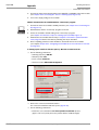
9.
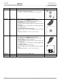
Switch on your PC and start WindowsTM (minimum requirement: Windows 95TM).
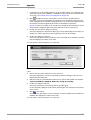
10. Install the "CLV-Setup" software and the online CLV-Setup Help from the CD-ROM
("Manuals & Software") on your PC.
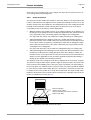
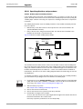
11. Connect the PC to the auxiliary interface of the CLV490. To do so, connect a 3-core
RS 232 data cable (null modem cable), e. g. no. 2014054 to the "Aux" plug in the
CDB420 or CDM490.
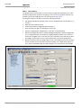
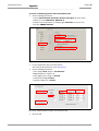
12. Start the "CLV-Setup" program.
CLV-Setup establishes communication with the CLV490 and uploads the parameter
set. The parameters are then displayed on the tabs.
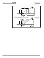
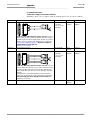
13. Carry out a test read using test bar codes (clock the CLV490 accordingly).
Display the reading result in the Terminal Emulator window of the "CLV-Setup" program.
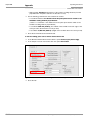
14. Configure the CLV490 for the application using the settings on the tabs in CLV-Setup.
Copy (download) the modified parameter set to the CLV490 temporarily.
Do not switch off the power supply to the CDB420 or CDM490 (CLV490)!
15. Test the application under realistic conditions.
16. Check whether the data is transmitted correctly between the CLV490 and host.
17. If necessary, correct and optimize the parameter values.
Copy (download) the parameter set permanently to the CLV490.
CLV490 with external parameter memory connected:
Copy the modified parameter set to the external parameter memory when CLV-Setup
asks you for confirmation.
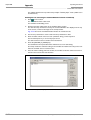
18. Save the parameter set as a configuration file "*.scl" in the "CLV-Setup" program.
The CLV490 can then be operated with the application-specific settings.
I-4
© SICK AG · Division Auto Ident · Germany · All rights reserved
8009993/RA61/2007-07-20
Operating Instructions
Contents
CLV490 Bar Code Scanner
Table of contents
1
1.1
1.2
1.2.1
1.2.2
1.3
1.4
2
2.1
2.1.1
2.1.2
2.1.3
2.2
2.3
2.4
2.4.1
2.4.2
2.5
2.5.1
2.5.2
3
3.1
3.1.1
3.1.2
3.1.3
3.1.4
3.1.5
3.2
3.2.1
3.2.2
3.2.3
3.2.4
3.2.5
3.3
3.3.1
3.3.2
4
4.1
4.2
4.2.1
4.2.2
4.2.3
4.2.4
4.2.5
4.2.6
4.2.7
4.2.8
4.3
4.3.1
4.3.2
4.3.3
4.4
4.4.1
4.4.2
4.4.3
8009993/RA61/2007-07-20
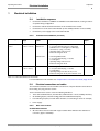
Notes on this document............................................................................................ 1-1
Purpose ....................................................................................................................................... 1-1
Target audience........................................................................................................................ 1-1
Mounting, electrical installation, maintenance and replacement.................... 1-1
Startup, operation and configuration......................................................................... 1-1
Information content................................................................................................................. 1-2
Symbols ....................................................................................................................................... 1-2
Safety information....................................................................................................... 2-1
Authorized users ...................................................................................................................... 2-1
Mounting and maintenance .......................................................................................... 2-1
Electrical installation and replacement ..................................................................... 2-1
Startup, operation and configuration......................................................................... 2-1
Intended use.............................................................................................................................. 2-1
General safety instructions and protection measures .............................................. 2-2
Quick stop and quick restart................................................................................................ 2-4
Stopping the CLV490...................................................................................................... 2-4
Restarting the CLV490 ................................................................................................... 2-4
Environmental information.................................................................................................... 2-4
Power requirements......................................................................................................... 2-4
Disposal after removal from service.......................................................................... 2-4
Product description .................................................................................................... 3-1
Design .......................................................................................................................................... 3-1
Scope of delivery............................................................................................................... 3-1
Variants ................................................................................................................................. 3-1
System requirements for stand-alone configuration........................................... 3-2
Product features and functions (overview) ............................................................. 3-3
Design ................................................................................................................................... 3-5
Method of operation............................................................................................................... 3-6
Autofocus function............................................................................................................ 3-7
Event-controlled dynamic focus control ................................................................... 3-8
Reading modes of the CLV490 in stand-alone configuration.......................... 3-8
Scan procedure variants ................................................................................................ 3-9
Additional components .................................................................................................3-10
Indicators and control elements ......................................................................................3-10
Control elements.............................................................................................................3-10
Function of the LEDs......................................................................................................3-11
Installation..................................................................................................................... 4-1
Installation sequence ............................................................................................................. 4-1
Preparations............................................................................................................................... 4-1
Required components..................................................................................................... 4-1
Required accessories...................................................................................................... 4-1
Required auxiliary parts .................................................................................................. 4-1
Replacing the laser warning label ............................................................................... 4-2
Selecting the mounting location .................................................................................. 4-2
Mounting accessories ..................................................................................................... 4-2
Distance between the CLV490 and the object..................................................... 4-4
Count direction of the reading angle RA and code angle CW.......................... 4-6
Mounting and adjusting the device................................................................................... 4-7
Mounting the CLV490 ..................................................................................................... 4-7
Adjusting the CLV490 ..................................................................................................... 4-8
Adjusting mode ................................................................................................................4-10
Mounting the external components................................................................................4-11
Mounting the CDB420 or CDM490 Connection Module................................4-11
Mounting the external reading pulse sensor........................................................4-11
Installing incremental encoder ...................................................................................4-12
© SICK AG · Division Auto Ident · Germany · All rights reserved
I-5
Contents
Operating Instructions
CLV490 Bar Code Scanner
4.4.4
4.5
5
5.1
5.1.1
5.2
5.2.1
5.2.2
5.2.3
5.2.4
5.2.5
5.3
5.3.1
5.3.2
5.3.3
5.3.4
5.3.5
5.3.6
5.3.7
5.3.8
5.3.9
5.4
5.4.1
5.4.2
5.4.3
5.5
5.5.1
5.5.2
5.5.3
5.5.4
5.5.5
5.5.6
5.5.7
5.5.8
5.5.9
6
6.1
6.2
6.2.1
6.2.2
6.3
6.3.1
6.4
6.4.1
6.4.2
6.4.3
6.4.4
6.5
6.5.1
6.5.2
6.5.3
6.5.4
I-6
Mounting the sensors for detecting the object distance ................................ 4-13
Dismantling the device........................................................................................................ 4-14
Electrical installation ................................................................................................. 5-1
Installation sequence............................................................................................................. 5-1
SICK Connection Modules (overview)...................................................................... 5-1
Electrical connections and cables ..................................................................................... 5-1
Wire cross-sections .......................................................................................................... 5-1
Prefabricated cables (overview) .................................................................................. 5-2
Connections/cables for the CDB420 Connection Modules ............................. 5-3
Connections/cables for the CDM490 Connection Module .............................. 5-5
Connections/cables for a non-SICK power pack .................................................. 5-6
Connector pin assignment.................................................................................................... 5-7
Terminals on the CLV490 .............................................................................................. 5-7
Cable no. 2027046 (connector cover)
Cable no. 2030023 (connector cover with parameter memory) .................. 5-8
Cable no. 2020307 (connector cover with parameter memory) .................. 5-9
Cable no. 2033126/2033127 (connector cover with
parameter memory) ...................................................................................................... 5-10
Cable no. 2030065/2031034 (connector cover with
parameter memory) ...................................................................................................... 5-11
Cable no. 2020303 ...................................................................................................... 5-13
Cable no. 2020264 ...................................................................................................... 5-13
Cable no. 2020981 (connector cover with parameter memory) ............... 5-14
Cable no. 2021267 (connector cover) ................................................................. 5-15
Preparations for electrical installation............................................................................ 5-16
Requirements for the host interface ....................................................................... 5-16
Supply voltage ................................................................................................................. 5-16
Non-SICK Power supply unit/connections without the
Connection Module........................................................................................................ 5-17
Electrical installation procedure ....................................................................................... 5-18
Individual steps................................................................................................................ 5-18
Tools .................................................................................................................................... 5-18
Connecting the supply voltage .................................................................................. 5-18
Connecting the host interface ................................................................................... 5-20
Connecting the CAN interface ................................................................................... 5-21
Connecting the PC.......................................................................................................... 5-21
Connecting the "Sensor" switching input .............................................................. 5-22
Connecting the "IN 0" to "IN 4" switching inputs............................................... 5-23
Connecting the "Result 1" to "Result 4" switching outputs ........................... 5-26
Operation ....................................................................................................................... 6-1
Overview of steps for starting up the CLV490.............................................................. 6-1
Default settings ......................................................................................................................... 6-1
Default settings of the line scanner CLV490 (all variants)................................ 6-2
Default settings of the line scanner with oscillating mirror
CLV490 (all variants)........................................................................................................ 6-2
Quick start ................................................................................................................................... 6-3
Starting up the CLV490 with the factory default settings.................................. 6-3
Configuring (parameterization) the CLV490 .................................................................. 6-5
Configuring the CLV490 via the user interface of CLV-Setup .......................... 6-5
Function of the tabs in CLV-Setup (overview) ........................................................ 6-7
Parameterizing example ................................................................................................. 6-9
Guide to parameterization menu................................................................................. 6-9
Operating modes and outputing the reading result ................................................. 6-38
Reading mode (standard operating mode).......................................................... 6-38
Percentage evaluation.................................................................................................. 6-41
Adjusting mode................................................................................................................ 6-43
Background teach-in ..................................................................................................... 6-44
© SICK AG · Division Auto Ident · Germany · All rights reserved
8009993/RA61/2007-07-20
Operating Instructions
Contents
CLV490 Bar Code Scanner
6.5.5
Show RA-limits..................................................................................................................6-46
6.5.6
Background Analysis......................................................................................................6-47
6.5.7
I/O monitor in increment trigger ................................................................................6-48
6.5.8
Displaying and editing operating data.....................................................................6-53
6.5.9
Reading diagnosis...........................................................................................................6-54
6.5.10 Monitor Host Interface ..................................................................................................6-54
6.5.11 Auxiliary input ....................................................................................................................6-56
6.5.12 Code statistics for RDT400.........................................................................................6-56
6.5.13 Self-test...............................................................................................................................6-57
6.5.14 Executing CLV490 functions interactively .............................................................6-58
6.6
CLV490 messages ...............................................................................................................6-59
6.6.1
Displaying messages.....................................................................................................6-59
6.6.2
Error messages ...............................................................................................................6-59
6.7
Switching off the CLV490 ...................................................................................................6-60
7
Maintenance ................................................................................................................. 7-1
7.1
Maintenance during operation............................................................................................ 7-1
7.2
Cleaning the CLV490 ............................................................................................................. 7-1
7.2.1
Cleaning the front window ............................................................................................. 7-1
7.2.2
Cleaning other optical surfaces ................................................................................... 7-2
7.3
Checking the incremental encoder ................................................................................... 7-3
7.4
Disposal....................................................................................................................................... 7-3
8
Troubleshooting ........................................................................................................... 8-1
8.1
Overview of possible errors and malfunctions ............................................................. 8-1
8.1.1
Mounting errors ................................................................................................................. 8-1
8.1.2
Electrical installation errors............................................................................................ 8-1
8.1.3
Parameter errors............................................................................................................... 8-1
8.1.4
Malfunctions........................................................................................................................ 8-1
8.2
Monitoring error and malfunctions .................................................................................... 8-1
8.3
Error messages ........................................................................................................................ 8-2
8.3.1
CLV490 without external parameter memory ....................................................... 8-2
8.3.2
LED error messages for the external parameter memory
(connector cover).............................................................................................................. 8-3
8.3.3
Messages for errors accessing the external parameter memory
(connector cover).............................................................................................................. 8-5
8.4
ST error status in the reading result of a bar code..................................................... 8-7
8.5
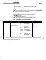
Troubleshooting........................................................................................................................ 8-9
8.5.1
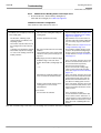
General malfunctions: CLV490 not ready ............................................................... 8-9
8.5.2
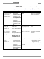
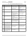
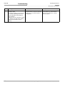
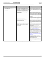
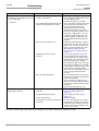
Malfunctions in Reading mode: reading trigger errors......................................8-10
8.5.3
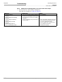
Malfunctions in Reading mode: result output errors .........................................8-14
8.5.4
Malfunctions in Reading mode: errors in the result status output...............8-18
8.5.5
Malfunctions in Reading mode: oscillating mirror errors..................................8-19
8.6
SICK Support ...........................................................................................................................8-20
9
Technical data .............................................................................................................. 9-1
9.1
Data sheet CLV490-0010/-2010/-6010 bar code scanner ................................ 9-1
9.2
Data sheet CLV490-1010/-3010/-7010 bar code scanner ................................ 9-2
9.3
Data sheet CLV490-0011 /-2011/-6011 bar code scanner............................... 9-3
9.4
Data sheet CLV490-1011/-3011/-7011 bar code scanner ................................ 9-3
9.5
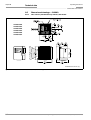
Dimensioned drawings – CLV490 .................................................................................... 9-4
9.5.1
Line scanner (standard device) without /with heater ......................................... 9-4
9.5.2
Line scanner with oscillating mirror (without/with heater)................................. 9-5
10
Appendix ..................................................................................................................... 10-1
10.1 Overview....................................................................................................................................10-1
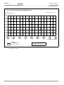
10.2 Specification diagrams.........................................................................................................10-1
10.2.1 Reading conditions for all diagrams.........................................................................10-1
10.2.2 Overview of diagrams....................................................................................................10-2
10.2.3 Standard density: Reading performance data of line scanner......................10-3
10.2.4 Standard density: Reading performance data of line scanner with
8009993/RA61/2007-07-20
© SICK AG · Division Auto Ident · Germany · All rights reserved
I-7
Contents
Operating Instructions
CLV490 Bar Code Scanner
oscillating mirror .............................................................................................................. 10-9
High density: Reading performance data of line scanner............................ 10-16
High density: Reading performance data line scanner
with oscillating mirror.................................................................................................. 10-21
10.2.7 Low density: Reading performance data of line scanner............................. 10-27
10.2.8 Low density: Reading performance data of line scanner
with oscillating mirror.................................................................................................. 10-31
10.3 Installing and operating the external parameter memory
(connector cover)............................................................................................................... 10-34
10.3.1 Function of the external parameter memory.................................................... 10-35
10.3.2 Installation and electrical connection................................................................... 10-36
10.3.3 Operation ........................................................................................................................ 10-36
10.3.4 Switching on the device for the first time........................................................... 10-37
10.3.5 Adjusting the parameter set in the external parameter memory
(connector cover) after it has been downloaded to the CLV490 ............ 10-37
10.3.6 Meaning of the LEDs.................................................................................................. 10-38
10.3.7 Error messages............................................................................................................ 10-38
10.3.8 Replacing a CLV490................................................................................................... 10-39
10.4 Optional heating .................................................................................................................. 10-40
10.4.1 Features .......................................................................................................................... 10-40
10.4.2 Design.............................................................................................................................. 10-40
10.4.3 Function........................................................................................................................... 10-40
10.4.4 Electrical installation ................................................................................................... 10-41
10.4.5 Outdoor applications .................................................................................................. 10-41
10.5 System messages ............................................................................................................. 10-42
10.5.1 CLV490 without external parameter memory.................................................. 10-42
10.5.2 CLV490 with external parameter memory connected ................................. 10-42
10.6 Installing and operating the "CLV-Setup" program................................................ 10-43
10.6.1 Preparations .................................................................................................................. 10-43
10.6.2 Installing the software................................................................................................ 10-43
10.6.3 Starting CLV-Setup...................................................................................................... 10-46
10.6.4 User interface................................................................................................................ 10-48
10.6.5 Functions ........................................................................................................................ 10-49
10.6.6 Hot keys .......................................................................................................................... 10-49
10.6.7 Opening and closing tabs......................................................................................... 10-50
10.6.8 Online help – CLV-Setup Help ................................................................................ 10-50
10.6.9 Transferring parameter sets between CLV-Setup and
the CLV490 ................................................................................................................... 10-51
10.6.10 Unknown parameters................................................................................................. 10-51
10.6.11 Log file in the Terminal Emulator ........................................................................... 10-52
10.6.12 Starting CLV-Setup with an "INI file" as an argument.................................... 10-52
10.6.13 The CLV Assistant........................................................................................................ 10-52
10.7 Configuring a CLV490 with command strings......................................................... 10-53
10.8 Calculating parameter values for setting the CLV490......................................... 10-55
10.8.1 Calculating the number of scans (for standard decoder)............................ 10-55
10.8.2 Calculating the start position and mirror speed for the forward
and return phase of the One-Shot function ...................................................... 10-57
10.8.3 Calculating the necessary capture area for the bar code if
several bar codes are read on each object...................................................... 10-58
10.9 Tables ..................................................................................................................................... 10-59
10.9.1 Calculating the code length of a bar code......................................................... 10-59
10.10 Discussion of a parameterization example .............................................................. 10-60
10.10.1 Application Conditions ............................................................................................... 10-60
10.10.2 Purpose of this discussion ....................................................................................... 10-60
10.10.3 Instructions for solution – step by step .............................................................. 10-60
10.10.4 Important clarifications .............................................................................................. 10-61
10.10.5 Mounting and electrical connection ..................................................................... 10-61
10.2.5
10.2.6
I-8
© SICK AG · Division Auto Ident · Germany · All rights reserved
8009993/RA61/2007-07-20
Operating Instructions
Contents
CLV490 Bar Code Scanner
10.10.6 Parameterize the CLV490 with the "CLV-Setup" program ..........................10-62
10.10.7 Testing the application ...............................................................................................10-68
10.11 Special applications and procedures..........................................................................10-69
10.11.1 Auxiliary input via auxiliary interface ......................................................................10-69
10.11.2 Connection to Profibus DP........................................................................................10-72
10.11.3 Connection to the DeviceNet ..................................................................................10-72
10.11.4 Connection to Ethernet TCP/IP ...............................................................................10-72
10.11.5 Building a CAN Scanner Network...........................................................................10-72
10.11.6 Integration in an OPS reading system..................................................................10-72
10.12 Replacing a CLV490 (copying the parameter set) ................................................10-73
10.12.1 Downloading the parameter set.............................................................................10-73
10.12.2 Importing the parameter set from the external memory..............................10-74
10.13 Ordering Information..........................................................................................................10-75
10.13.1 CLV490 Bar Code Scanner......................................................................................10-75
10.13.2 Accessories: Mounting devices..............................................................................10-75
10.13.3 Accessories: Hoods ....................................................................................................10-75
10.13.4 Accessories: Connection modules........................................................................10-76
10.13.5 Accessories: Extensions for connection modules...........................................10-77
10.13.6 Accessories: Cables, external parameter memories in
connector cover, connector covers ......................................................................10-79
10.13.7 Plug-in connections .....................................................................................................10-82
10.13.8 Reading pulse generators.........................................................................................10-82
10.13.9 Incremental encoder...................................................................................................10-82
10.14 Dimensioned drawings of the accessories...............................................................10-83
10.14.1 Angle bracket, single no. 2013824......................................................................10-83
10.14.2 Articulated bracket, No. 2018435........................................................................10-83
10.14.3 Quick clamping device, No. 2016110.................................................................10-83
10.14.4 Hinge bracket, No. 2022996..................................................................................10-84
10.14.5 Mirror hood, No. 2032070 ......................................................................................10-84
10.15 Supplementary documentation .....................................................................................10-85
10.15.1 CLV Connect (from version 1.9) ...........................................................................10-85
10.16 Glossary..................................................................................................................................10-86
10.17 EC Declaration of Conformity .........................................................................................10-94
10.18 Index ........................................................................................................................................10-95
10.19 Bar code example ...........................................................................................................10-101
8009993/RA61/2007-07-20
© SICK AG · Division Auto Ident · Germany · All rights reserved
I-9
Figures and tables
Operating Instructions
CLV490 Bar Code Scanner
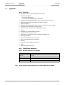
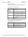
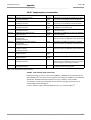
Abbreviations
CAN
Controller Area Network (standard field bus system with message-orientated data exchange protocol)
CDB
Connection Device Basic
CDM
Connection Device Modular
CMF
Connection Module Fieldbus
CLV
Code-Leser V-Prinzip.
CMC
Connection Module Cloning
CMD
Connection Module Display
CMP
Connection Module Power
DC
DOF
EEPROM
FIFO
HD
HTML
Distance Configuration
Depth Of Field
Electrically Erasable Programmable Read Only Memory
First in, first out
High Density
Hyper Text Markup Language (page-description language on the internet)
LED
Light Emitting Diode
LIFO
Last in, first out
MTBF
PLC
Mean Time Between Failure
Programmable Logic Controller
RAM
Ramdom Acces Memory
ROM
Read Only Memory
RTF
SMART
Rich Text Format (standard document format with format descriptions)
SICK Modular Advanced Recognition Technology
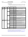
Tables
Table 3-1:
Table 3-2:
Table 3-3:
Table 4-1:
Table 5-1:
Table 5-2:
Table 5-3:
Table 5-4:
Table 5-5:
Table 5-6:
Table 5-7:
Table 5-8:
Table 5-9:
Table 5-10:
Table 5-11:
Table 5-12:
Table 5-13:
I-10
CLV490 variants................................................................................................................ 3-1
Meaning of LEDs: CLV490 without external parameter memory ................3-11
Meaning of LEDs: CLV490 with external parameter memory in the
connector cover...............................................................................................................3-12
Permissible reading angles between the scan line and bar code ................. 4-5
Connection Modules for the CLV490 ....................................................................... 5-1
Cables for connecting the CLV490............................................................................ 5-2
Pin assignment of the 15-pin D Sub HD "Host/Term" plug ............................. 5-7
Pin assignment of the 15-pin D Sub HD "I/O" socket........................................ 5-7
Pin assignment: 15-pin D Sub HD plug of the cable no. 2027046/
no. 2030023...................................................................................................................... 5-8
Pin assignment: 15-pin D Sub HD plug of the cable no. 2020307.............. 5-9
Pin assignment: 15-pin D Sub HD socket of the cable no. 2020307......... 5-9
Pin assignment: 15-pin D Sub HD plug of the cable no. 2033126/
no. 2033127....................................................................................................................5-10
Pin assignment: open end of the cable no. 2033126/no. 2033127 .......5-10
Pin assignment: 15-pin D Sub HD plug of the cable no. 2030065/
no. 2031034....................................................................................................................5-11
Pin assignment: 15-pin D Sub HD socket of the cable no. 2030065/
no. 2031034....................................................................................................................5-11
Pin assignment: open end of the cable no. 2030065/no. 2031034 .......5-12
Pin assignment: 15-pin D Sub HD socket/wire colors of cable
© SICK AG · Division Auto Ident · Germany · All rights reserved
8009993/RA61/2007-07-20
Operating Instructions
Figures and tables
CLV490 Bar Code Scanner
Table 5-14:
Table 5-15:
Table 5-16:
Table 5-17:
Table 5-18:
Table 5-19:
Table 5-20:
Table 5-21:
Table 5-22:
Table 5-23:
Table 5-24:
Table 5-25:
Table 5-26:
Table 5-27:
Table 5-28:
Table 5-29:
Table 6-1:
Table 6-2:
Table 6-3:
Table 6-4:
Table 6-5:
Table 6-6:
Table 6-7:
Table 6-8:
Table 6-9:
Table 6-10:
Table 6-11:
Table 6-12:
Table 6-13:
Table 6-14:
Table 6-15:
Table 6-16:
Table 6-17:
Table 6-18:
Table 6-19:
Table 6-20:
Table 6-21:
Table 6-22:
Table 6-23:
8009993/RA61/2007-07-20
no. 2020303 ................................................................................................................... 5-13
Pin assignment: 15-pin D Sub HD plug/wire colors of cable
no. 2020264 ................................................................................................................... 5-13
Wire colors of cable no. 2020981, cable 1 ("Host/Term" connection) ... 5-14
Wire colors of cable no. 2020981, cable 2 ("I/O" connection)................... 5-14
Wire colors of cable no. 2021267, cable 1 (connection for data
and function interfaces) ............................................................................................... 5-15
Wire colors of cable no. 2021267, cable 2 (connection for
power supply)................................................................................................................... 5-15
Maximum cable lengths between the CLV490 and host ............................... 5-16
Power consumption of the CLV490 ........................................................................ 5-16
Power-up delay as a function of the device number GN ................................ 5-16
Communication parameters for the host interface (default setting) .......... 5-20
Characteristic data of the "Sensor" switching input.......................................... 5-22
Pin assignment for "IN 0" to IN 4" switching inputs.......................................... 5-24
Characteristic data of the "IN 0" to "IN 4" switching inputs .......................... 5-24
Dynamic focus control: switching inputs/distance configuration
assignment table ............................................................................................................ 5-24
Combination of the functions of the "IN 0" to "IN 4" switching inputs ...... 5-25
Pin assignment for "Result 1" to "Result 4" switching outputs .................... 5-26
Characteristic data of the "Result 1" to "Result 4" switching outputs....... 5-26
Extract: Default parameter settings of the line scanner
CLV490-0010/-0011 .....................................................................................................6-2
Extract: Default parameter settings of the line scanner with
oscillating mirror CLV490 ...............................................................................................6-2
Reading distances for default settings......................................................................6-4
Guide: Configuring the reading area........................................................................ 6-11
Guide: Selecting the focus control mode.............................................................. 6-12
Guide: Configuring the autofocus function (part 1) ........................................... 6-13
Configuring the autofocus function (part 2) ......................................................... 6-15
Guide: Configuring focus position switchover...................................................... 6-16
Guide: Configuring oscillating mirror functions .................................................... 6-17
Overview: CLV490 applications in stand-alone configuration or in
arrangement with OTS400 ......................................................................................... 6-21
Guide: Parameterizing the reading trigger for start/stopp mode
in stand-alone configuration ....................................................................................... 6-22
Guide: Parameterzing internal object tracking..................................................... 6-27
Guide: Parameterizing the reading mode for tracking mode
in stand-alone configuration ....................................................................................... 6-29
Guide: Parameterizing focus control in CLV490 for master/
slaves arrangement with OTC400 ........................................................................... 6-30
Guide: Parameterizing reading trigger in the CLV490 for master/
slave arrangement with OTC400 ............................................................................. 6-31
Guide: Parameterizing slave mode in the CLV490 for arrangement
with OTC400 (master) .................................................................................................. 6-31
Guide: Parameterizing operation mode in the OTC400 for master/
slaves arrangement....................................................................................................... 6-32
Guide: Parameterizing focus control in CLV490 for object tracking
mode with OTC400 ....................................................................................................... 6-33
Guide: Parameterizing reading trigger in the CLV490 for object
tracking mode with OTC400 ...................................................................................... 6-34
Guide: Parameterizing tracking in the CLV490 for object tracking
mode with OTC400 ....................................................................................................... 6-34
Guide: Parameterizing slave mode in the CLV490 for object
tracking mode with OTC400 ...................................................................................... 6-35
Guide: Parameterizing tracking mode in the OTC400...................................... 6-35
Guide: Parameterizing the laser timeout ............................................................... 6-36
© SICK AG · Division Auto Ident · Germany · All rights reserved
I-11
Figures and tables
Operating Instructions
CLV490 Bar Code Scanner
Table 6-24:
Table 6-25:
Table 8-1:
Table 8-2:
Table 8-3:
Table 8-4:
Table 8-5:
Table 8-6:
Table 8-7:
Table 8-8:
Table 8-9:
Table 8-10:
Table 8-11:
Table 9-1:
Table 9-2:
Table 9-3:
Table 9-4:
Table 10-1:
Table 10-2:
Table 10-3:
Table 10-4:
Table 10-5:
Table 10-6:
Table 10-7:
Table 10-8:
Table 10-9:
Table 10-10:
Table 10-11:
Table 10-12:
Table 10-13:
Table 10-14:
Table 10-15:
Table 10-16:
Table 10-17:
Table 10-18:
Table 10-19:
Table 10-20:
I-12
Guide: Parameterizing the separation of identical bar codes........................6-36
"Monitor Host Interface" function .............................................................................6-54
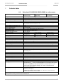
Error messages output on the auxiliary interface................................................. 8-2
LED error messages for access to the external parameter memory
(connector cover).............................................................................................................. 8-3
Messages for problems accessing the external parameter memory
(connector cover).............................................................................................................. 8-5
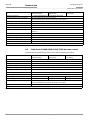
Meaning of the ST error status in the reading result .......................................... 8-7
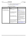
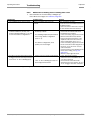
Troubleshooting: restoring operation (Reading mode)....................................... 8-9
Troubleshooting: reading trigger errors in Reading mode
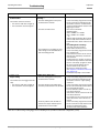
(CLV490 in stand-alone configuration)...................................................................8-10
Troubleshooting: reading trigger errors in Reading mode
(CLV490 integrated in OTS400 Omni Tracking System).................................8-13
Troubleshooting: result output errors in Reading mode
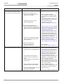
(CLV490 in stand-alone configuration)...................................................................8-14
Troubleshooting: result output errors in Reading mode
(CLV490 integrated in the OTS400 Omni Tracking System).........................8-17
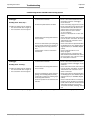
Troubleshooting: errors in the result status output in Reading mode ........8-18
Troubleshooting: oscillating mirror errors in Reading mode ...........................8-19
Technical specifications of the CLV490-0010/-2010/-6010........................ 9-1
Technical specifications of the CLV490-1010/-3010/-7010........................ 9-2
Technical specifications of the CLV490-0011/-2011/-6011........................ 9-3
Technical specifications of the CLV490-1011/-3011/-7011........................ 9-3
Reading conditions for specification diagrams ....................................................10-1
Overview of specification diagrams for the line scanner .................................10-2
Overview of specification diagrams for the line scanner with
oscillating mirror...............................................................................................................10-2
Types of the external parameter memory in the connector cover...........10-34
CLV490 system messages......................................................................................10-42
Additional CLV490 system messages for the connected
parameter memory .....................................................................................................10-42
Default settings in CLV-Setup..................................................................................10-46
Formulas for calculating the code length of a bar code ...............................10-59
Communication parameters on the terminal/PC for the auxiliary
input ..................................................................................................................................10-71
Communication parameter settings for the SICK Hand-held
Scanner from the IT 38xx/46xx/48xx/58xx series........................................10-71
CLV490 variants...........................................................................................................10-75
Accessories: mounting accessories .....................................................................10-75
Accessories: Hood.......................................................................................................10-75
Accessories: connection modules.........................................................................10-76
Accessories: Extensions for connection modules...........................................10-77
Accessories: Cables and connector covers for CLV490 without
heater ...............................................................................................................................10-79
Accessories: Cables and connector covers for CLV490 with heater......10-81
Accessories: plug-in connections ..........................................................................10-82
Accessories: incremental encoder........................................................................10-82
Supplementary documentation ..............................................................................10-85
© SICK AG · Division Auto Ident · Germany · All rights reserved
8009993/RA61/2007-07-20
Operating Instructions
Figures and tables
CLV490 Bar Code Scanner
Figures
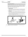
Fig. 2-1:
Fig. 3-1:
Fig. 3-2:
Fig. 3-3:
Fig. 3-4:
Fig. 3-5:
Fig. 3-6:
Fig. 4-1:
Fig. 4-2:
Fig. 4-3:
Fig. 4-4:
Fig. 4-5:
Fig. 4-6:
Fig. 4-7:
Fig. 4-8:
Fig. 4-9:
Fig. 4-10:
Fig. 4-11:
Fig. 5-1:
Fig. 5-2:
Fig. 5-3:
Fig. 5-4:
Fig. 5-5:
Fig. 5-6:
Fig. 5-7:
Fig. 6-1:
Fig. 6-2:
Fig. 6-3:
Fig. 6-4:
Fig. 6-5:
Fig. 6-6:
Fig. 6-7:
Fig. 6-8:
Fig. 6-9:
Fig. 6-10:
Fig. 6-11:
Fig. 6-12:
Fig. 6-13:
Fig. 6-14:
Fig. 6-15:
Fig. 6-16:
Fig. 6-17:
Fig. 6-18:
Fig. 6-19:
Fig. 7-1:
Fig. 7-2:
8009993/RA61/2007-07-20
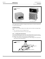
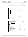
Laser warning labels on the CLV490 ............................................................................2-3
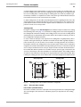
Design of the CLV490 ........................................................................................................3-5
Block diagram: CLV490 functions..................................................................................3-6
Optimization of the depth of field for the object .......................................................3-7
Dynamic focus control: classification of the reading range in
distance configurations.......................................................................................................3-8
Reading modes of the CLV490 in stand-alone configuration..............................3-9
LEDs........................................................................................................................................ 3-11
Line scanner: replacing the laser warning labels......................................................4-2
Line scanner: position of the securing threads on the CLV490.........................4-3
Line scanner: Mounting possibilities of the CLV490...............................................4-3
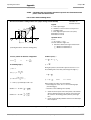
Scanning methods: alignment with bar code and conveyor direction..............4-4
Definition of the reading distance "a" and of the aperture angle a...................4-4
Line scanner: Reading angle between the scan line and the bar code...........4-5
Avoiding surface reflections: Angle between the emitted light and the
bar code (tilted away from the vertical axis) ..............................................................4-5
Count direction of the reading angle RA in the scan line and of the
code angle CW for the oscillating mirror ......................................................................4-6
Line scanner: scan line in Adjusting mode............................................................... 4-10
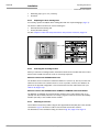
Line scanner: mounting example for the external reading pulse sensor ..... 4-11
Mounting example for object distance detection .................................................. 4-13
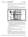
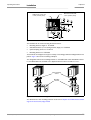
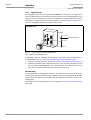
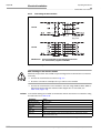
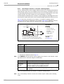
Block diagram: Connection of the CLV490 to the CDB420
connection module...............................................................................................................5-3
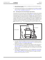
Block diagram: Connection of the CLV490 to the CDM490
connection module...............................................................................................................5-5
Connecting the host interface....................................................................................... 5-20
Connecting the auxiliary interface................................................................................ 5-21
Connections of the "Sensor" switching input.......................................................... 5-22
Connections of the "IN 0" to "IN 4" switching inputs .......................................... 5-23
Connections of the "Result 1" to "Result 4" switching outputs....................... 5-26
Bar code pattern (Code 39; module width 0.35 mm (11.8 mil);
Print ratio 2:1) ........................................................................................................................6-4
Narrowing the reading space using limit values..................................................... 6-10
Narrowing the autofocus range using limit values ................................................ 6-15
Oscillating mirror: "Oscillating with fixed amplitude" mode ................................ 6-18
Oscillating mirror: "Oscillating with variable amplitude" mode.......................... 6-19
One-Shot: Object tracking (bar code read from front)......................................... 6-20
CLV-Setup: Displaying the reading result of the termianl interface
in the Terminal Emulator ................................................................................................. 6-39
Reading result of the auxiliary interface: structure for "Good Read" ............. 6-40
Reading result of the auxiliary interface: structure for "No Read" .................. 6-40
CLV-Setup: Displaying the percentage evaluation in the Terminal
Emulator ................................................................................................................................ 6-42
CLV-Setup: Dialog window for running the background teach-in..................... 6-44
CLV-Setup: Display of th learned background ........................................................ 6-45
Appearance of scan line in the "Show RA-limits" mode ..................................... 6-46
CLV-Setup: Example of output in the "Background Analysis" dialog box..... 6-47
CLV-Setup: Selection of the signals to be displayed in I/O Monitoring......... 6-49
CLV-Setup: Example of output in the "I/O Monitoring" dialog box.................. 6-50
CLV-Setup: "Operating Data" dialog box................................................................... 6-53
CLV-Setup: Displaying the reading result of the host interface in the
Terminal Emulator with direction identifier at the beginning (in this case:
O = Output) .......................................................................................................................... 6-55
CLV-Setup: Displaying the self-test result in the Terminal Emulator .............. 6-57
Cleaning the reading window............................................................................................7-2
Cleaning the external optical sensors (reading pulse generator,
© SICK AG · Division Auto Ident · Germany · All rights reserved
I-13
Figures and tables
Operating Instructions
CLV490 Bar Code Scanner
Fig. 9-1:
Fig. 9-2:
Fig. 10-1:
Fig. 10-2:
Fig. 10-3:
Fig. 10-4:
Fig. 10-5:
Fig. 10-6:
Fig. 10-7:
Fig. 10-8:
Fig. 10-9:
Fig. 10-10:
Fig. 10-11:
Fig. 10-12:
Fig. 10-13:
Fig. 10-14:
Fig. 10-15:
Fig. 10-16:
Fig. 10-17:
Fig. 10-18:
Fig. 10-19:
Fig. 10-20:
I-14
object-height detector)....................................................................................................... 7-2
Dimensions of the CLV490 line scanner, front reading window ........................ 9-4
Dimensions of the CLV490: line scanner with oscillating mirror,
side reading window............................................................................................................ 9-5
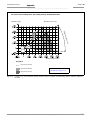
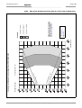
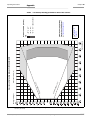
CLV490-0010/-0011 (Standard density): Reading field height as a
function of the reading distance and resolution.....................................................10-3
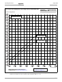
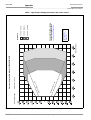
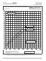
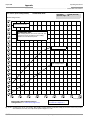
CLV490-0010/-0011 (Standard density): Min. and Max. reading
distance (measured radially) as a function of the focus position at a
resolution of 0.35 mm (13.8 mil) and an aperture angle of α = 40°...........10-4
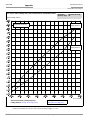
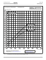
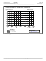
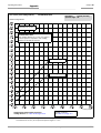
CLV490-0010/-0011 (Standard density): Min. and Max. reading
distance (measured radially) as a function of the focus position at a
resolution of 0.35 mm (13.8 mil) and an aperture angle of α = 56°...........10-5
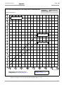
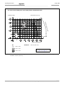
CLV490-0010/-0011 (Standard density): Min. and Max. reading
distance (measured radially) as a function of the focus position at a
resolution of 0.50 mm (19.7 mil) and an aperture angle of α = 40°...........10-6
CLV490-0010/-0011 (Standard density): Min. and Max. reading
distance (measured radially) as a function of the focus position at a
resolution of 0.50 mm (19.7 mil) and an aperture angle of α = 56°...........10-7
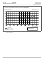
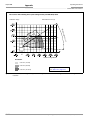
Characteristics field CLV490-0010/-0011 (Standard density): Scanning
frequency as a function of the radial reading distance and resolution .........10-8
CLV490-1010/-1011 (Standard density): Reading field height as a
function of the reading distance and resolution.....................................................10-9
CLV490-1010/-1011 (Standard density): Min. and Max. reading
distance (measured radially) as a function of the focus position at a
resolution of 0.35 mm (13.8 mil) and an aperture angle of α = 40°........10-10
CLV490-1010/-1011 (Standard density): Min. and Max. reading
distance (measured radially) as a function of the focus position at a
resolution of 0.35 mm (13.8 mil) and an aperture angle of α = 50°........10-11
CLV490-1010/-1011 (Standard density): Min. and Max. reading
distance (measured radially) as a function of the focus position at a
resolution of 0.50 mm (19.7 mil) and an aperture angle of α = 40°........10-12
CLV490-1010/-1011 (Standard density): Min. and Max. reading
distance (measured radially) as a function of the focus position at a
resolution of 0.50 mm (19.7 mil) and an aperture angle of α = 50°........10-13
Characteristics field CLV490-1010/-1011 (Standard density):
Scanning frequency as a function of the radial reading distance
and resolution ...................................................................................................................10-14
CLV490-1010/-1011 (Standard density): deflection range as a
function of radial reading distance, deflection angle and resolution ...........10-15
CLV490-2010/-2011 (High density): Reading field height as a
function of the reading distance and resolution..................................................10-16
CLV490-2010/-2011 (High density): Min. and Max. reading
distance (measured radially) as a function of the focus position at a
resolution of 0.25 mm (9.8 mil) and an aperture angle of α = 40°...........10-17
CLV490-2010/-2011 (High density): Min. and Max. reading
distance (measured radially) as a function of the focus position at a
resolution of 0.35 mm (13.8 mil) and an aperture angle of α = 40°........10-18
CLV490-2010/-2011 (High density): Min. and Max. reading
distance (measured radially) as a function of the focus position at a
resolution of 0.35 mm (13.8 mil) and an aperture angle of α = 56°........10-19
Characteristics field CLV490-2010/-2011 (High density): Scanning
frequency as a function of the radial reading distance and resolution ......10-20
CLV490-3010/-3011 (High density): Reading field height as a
function of the reading distance and resolution..................................................10-21
CLV490-3010/-3011: (High density) Min. and Max. reading
distance (measured radially) as a function of the focus position at a
resolution of 0.25 mm (9.8 mil) and an aperture angle of α = 40°...........10-22
© SICK AG · Division Auto Ident · Germany · All rights reserved
8009993/RA61/2007-07-20
Operating Instructions
Figures and tables
CLV490 Bar Code Scanner
Fig. 10-21: CLV490-3010/-3011 (High density): Min. and Max. reading
distance (measured radially) as a function of the focus position at a
resolution of 0.35 mm (13.8 mil) and an aperture angle of α = 40° ....... 10-23
Fig. 10-22: CLV490-3010/-3011 (High density): Min. and Max. reading
distance (measured radially) as a function of the focus position at a
resolution of 0.35 mm (13.8 mil) and an aperture angle of α = 50° ....... 10-24
Fig. 10-23: Characteristics field CLV490-3010/-3011 (High density): Scanning
frequency as a function of the radial reading distance and resolution ...... 10-25
Fig. 10-24: CLV490-3010/-3011 (High density): Deflection range as a function
of radial reading distance, deflection angle and resolution ............................ 10-26
Fig. 10-25: CLV490-6010/-6011 (Low density): Reading field height as a function
of the reading distance and the tilt at a resolution of 0.5 mm (19.7 mil). 10-27
Fig. 10-26: CLV490-6010/-6011 (Low density): Min. and Max. reading
distance (measured radially) as a function of the focus position at a
resolution of 0.5 mm (19.7 mil) and an aperture angle of α = 40° .......... 10-28
Fig. 10-27: CLV490-6010/-6011 (Low density): Min. and Max. reading
distance (measured radially) as a function of the focus position at a
resolution of 0.5 mm (19.7 mil) and an aperture angle of α = 60° .......... 10-29
Fig. 10-28: Characteristics field CLV490-6010/-6011 (Low density): Scanning
frequency as a function of the radial reading distance and resolution ...... 10-30
Fig. 10-29: CLV490-7010/-7011 (Low density): Reading field height as a
function of the reading distance and tilt at a resolution of 0.5 mm
(19.7 mil)............................................................................................................................ 10-31
Fig. 10-30: Characteristics field CLV490-7010/-7011 (Low density): Scanning
frequency as a function of the radial reading distance and resolution ...... 10-32
Fig. 10-31: CLV490-7010/-7011 (Low density): Deflection range as a function
of radial reading distance, deflection angle and tilt at a resolution of
0.5 mm (19.7 mil) .......................................................................................................... 10-33
Fig. 10-32: External parameter memory, installed on the CLV490.................................... 10-34
Fig. 10-33: CLV-Setup: "Device configuration" tab with the CLV490 start options ..... 10-36
Fig. 10-34: CLV-Setup: dialog box for adjusting the external parameter memory ....... 10-38
Fig. 10-35: CLV490 with heater: temperature curve inside the housing......................... 10-40
Fig. 10-36: CLV-Setup: Result display of the AutoBaud Detect function.......................... 10-47
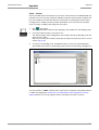
Fig. 10-37: User interface of the "CLV-Setup" software ......................................................... 10-48
Fig. 10-38: CLV-Setup: entering commands in the Terminal Emulator............................. 10-53
Fig. 10-39: Line scanner: calculating the number of scans for ladder-type
bar code arrangements................................................................................................ 10-55
Fig. 10-40: Line scanner: calculating the number of scans for fence-type
bar code arrangements................................................................................................ 10-55
Fig. 10-41: Line scanner with oscillating mirror: calculating the number of
scans for fence-type bar code positioning............................................................ 10-56
Fig. 10-42: One-Shot: Line scanner with oscillating mirror: calculating the
number of scans for fence-type bar code positioning...................................... 10-57
Fig. 10-43: Required distance between the bar codes on an object ................................ 10-58
Fig. 10-44: Parameterization example: prepare a sketch of the reading situation ...... 10-61
Fig. 10-45: Parameterization example: settings on the "Reading Configuration" tab . 10-62
Fig. 10-46: Parameterization example: "Autofocus Parameters" tab................................ 10-63
Fig. 10-47: Parameterization example: "Autofocus Limits" tab ........................................... 10-63
Fig. 10-48: Parameterization example: "Autofocus Optimizations" tab ............................ 10-64
Fig. 10-49: Parameterization example: Buttons on the "Device Configuration" tab.... 10-65
Fig. 10-50: Parameterization example: "Scanner Position Parameters" tab .................. 10-65
Fig. 10-51: Parameterization example: Settings on the "Device Configuration" tab ... 10-66
Fig. 10-52: Parameterization example: settings on the "Code Configuration" tab....... 10-67
Fig. 10-53: Parameterization example: "2/5 Interleaved" tab ............................................. 10-67
Fig. 10-54: Parameterization example: "Host interface" tab (default setting) ............... 10-68
Fig. 10-55: Parameterization example: "Data Strings" tab (default setting) ................... 10-68
Fig. 10-56: Auxiliary input via the auxiliary interface of the CLV490 .................................. 10-69
8009993/RA61/2007-07-20
© SICK AG · Division Auto Ident · Germany · All rights reserved
I-15
Figures and tables
Operating Instructions
CLV490 Bar Code Scanner
Fig. 10-57:
Fig. 10-58:
Fig. 10-59:
Fig. 10-60:
Fig. 10-61:
Fig. 10-62:
Fig. 10-63:
Fig. 10-64:
I-16
CLV-Setup: auxiliary input via the Terminal Emulator ........................................10-70
Dimensions of the angle bracket, single No. 2013824...................................10-83
Dimensions of the articulated bracket No. 2018435 ......................................10-83
Front view of quick clamping device No. 2016110 with angle
braket No. 2013824 .....................................................................................................10-83
Dimensions of the hinge bracket, No. 2022996................................................10-84
Dimensions of the mirror hood, No. 2032070 ...................................................10-84
Copy of the Declaration of Conformity (Page 1, scaled down)......................10-94
Scannable bar codes with various module widths (print ratio 2:1) ..........10-101
© SICK AG · Division Auto Ident · Germany · All rights reserved
8009993/RA61/2007-07-20
Operating Instructions
Notes on this document
Chapter 1
CLV490 Bar Code Scanner
1
Notes on this document
1.1
Purpose
This document is a guide to the operation of the bar code scanner
•
CLV490 with auto-focus
in the following variations:
•
Line scanner
– CLV490-2010, resolution from 0.20 mm (7.9 mil) (high density)
– CLV490-2011, resolution from 0.20 mm (7.9 mil) (high density), with heater
– CLV490-0010, resolution from 0.30 mm (11.8 mil) (standard density)
– CLV490-0011, resolution from 0.30 mm (11.8 mil) (standard density), with heater
– CLV490-6010, resolution from 0.40 mm (15.7 mil) (low density)
– CLV490-6011, resolution from 0.40 mm (15.7 mil) (low density), with heater
•
Line scanner with oscillating mirror
– CLV490-3010, resolution from 0.20 mm (7.9 mil) (high density)
– CLV490-3011, resolution from 0.20 mm (7.9 mil) (high density), with heater
– CLV490-1010, resolution from 0.30 mm (11.8 mil) (standard density)
– CLV490-1011, resolution from 0.30 mm (11.8 mil) (standard density), with heater
– CLV490-7010, resolution from 0.40 mm (15.7 mil) (low density)
– CLV490-7011, resolution from 0.40 mm (15.7 mil) (low density), with heater
This document provides information on
•
Mounting and connecting the device
•
Startup
•
Operating and configuring (parametrizing) the device
•
Maintenance
•
Exchanging the device without losing the parameter set
•
Special applications and procedures
The bar code scanner with all its variants will in this manual be referred to as the "CLV490",
except where a distinction is necessary.
1.2
Target audience
This document is intended for persons who are responsible for the following activities:
1.2.1
Mounting, electrical installation, maintenance and replacement
Electricians and service technicians.
1.2.2
Startup, operation and configuration
Technicians and engineers.
8009993/RA61/2007-07-20
© SICK AG · Division Auto Ident · Germany · All rights reserved
1-1
Notes on this document
Chapter 1
Operating Instructions
CLV490 Bar Code Scanner
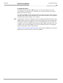
1.3
Information content
This document contains all the information required to mount, install, and start up the
CLV490 with the factory settings.
A series of step-by-step instructions is provided for each of these activities.
Configuration of the CLV490 for the application-specific reading situations is carried out
with the Windows-oriented PC software "CLV-Setup". Further assistance is also available in
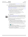
the form of the online help system CLV-Setup Help. The procedure for installing and operating the software is described in the appendix.
For further information on the design of the bar code scanner or on bar code technology in
general, please contact the Division Auto Ident at SICK AG.
Internet address: www.sick.com.
1.4
Symbols
Some of the information in this document is marked specially so that you can access it
quickly:
Warning
Warnings are provided to prevent injury to operating personal or serious damage to the bar
code scanner.
¾
Reference
Note
Explanation
Recommendation
Tip
Default
SCANNING FREQUENCY
Always read warnings carefully and observe them at all times.
Italics are used to refer to more detailed information elsewhere.
Indicates special features or characteristics.
Explanations provide background information on technical features.
Recommendations help you carry out certain procedures more effectively.
Tips explain settings in the user interface of the "CLV-Setup" program.
Marks a section containing the factory defaults.
This typeface is used to refer to a term in the "CLV-Setup" program.
Icons refer to buttons in the "CLV-Setup" program.
"Host receive fault"
This typeface is used for messages output via the auxiliary interface of the CLV490.
This symbol is used to mark sections that describe steps carried out with the "CLV-Setup"
program.
This symbol refers to additional technical documentation.
1-2
¾
There is a procedure which needs to be carried out. This symbol indicates operational instructions which only contain one operational step or operational steps in warning notices
which do not have to be followed in any particular order. Operational instructions comprising
several steps are denoted using consecutive numbers.
Ö
Here you select a function of the "CLV-Setup" user interface.
© SICK AG · Division Auto Ident · Germany · All rights reserved
8009993/RA61/2007-07-20
Safety information
Operating Instructions
Chapter 2
CLV490 Bar Code Scanner
2
Safety information
2.1
Authorized users
For the CLV490 to function correctly and safely, it must be mounted and operated by sufficiently qualified personnel.
Repairs to the CLV490 should only be carried out by qualified and authorized SICK AG
service staff.
The end user must be supplied with the operating instructions.
The end user must be provided with expert tuition and is advised to read the operating
instructions.
The following qualifications are required for the various tasks involved:
2.1.1
Mounting and maintenance
•
General technical training
•
Knowledge of the standard guidelines relating to safety at the workplace
2.1.2
Electrical installation and replacement
•
Practical training in electrical engineering
•
Knowledge of the standard safety guidelines relating to electrical engineering
•
Experience operating the devices in the relevant application (e. g. conveyor belt)
2.1.3
Startup, operation and configuration
•
Experience operating the devices in the relevant application (e. g. conveyor belt)
•
Knowledge of the hardware and software environment of the relevant application
(e. g. conveyor belt)
•
Basic understanding of Windows 95TM/98TM, Windows NT4.0TM, Windows 2000TM or
Windows XPTM
•
Ability to use an HTML browser (e. g. Internet ExplorerTM)
•
Basic understanding of data transfer methods
•
Basic understanding of bar code technology
2.2
Intended use
The CLV490 is designed to detect and decode bar codes automatically. It is mounted in a
reading station and reads bar codes on objects positioned on a conveyor belt, for example.
In stand-alone configuration the CLV490 transfers the data content of the decoded bar
codes via its host interface to a host computer for further processing. Being integrated in
the OTS400 Omni Tracking System together with other CLV490, the CLV490 transfers the
read results via its CAN interface to the OTC400 Omni Tracking Controller.
Note
8009993/RA61/2007-07-20
Any warranty claims against SICK AG shall be deemed invalid in the case of other system
use or system modifications, this includes modifications during installation and electrical installation, changes to the SICK software, or opening the device.
© SICK AG · Division Auto Ident · Germany · All rights reserved
2-1
Safety information
Chapter 2
Operating Instructions
CLV490 Bar Code Scanner
2.3
¾
General safety instructions and protection measures
Always read the general safety instructions carefully and observe them at all times.
Please also observe the warnings in front of the operating instructions in each chapter
of this document.
Risk of injury by electrical current
In the CDM490 Connection Module, the optional CMP490 Power Supply Module is connected to a mains voltage of 100 to 250 V AC/ 50 to 60 Hz.
¾
When working with electrical equipment, always follow the relevant safety specifications.
Laser beam can cause blindness.
The CLV490 uses a class 2 red-light laser. Looking directly at the laser beam can
seriously damage your eyesight.
The entire glass window acts as a laser outlet aperture.
Caution – use of controls or adjustments or performance of procedures other than those
specified herein may result in hazardous radiation exposure.
¾
As with sunlight, never look directly into the laser beam.
¾
Do not direct the laser beam at other persons.
¾
Mount and align the CLV490 in such a way to prevent the laser beam reflecting off
mirrored surfaces.
¾
Do not open the housing.
(Opening the housing does not deactivate the laser diode).
¾
Observe the laser protection specifications (latest version)
Laser power
The laser operates at a wave length of λ = 650 nm (visible red light). The power output at
the reading window is max. 2.8 mW. The emitted radiation is not dangerous to human skin.
The product is classified in laser class 2 (laser class II) in accordance with EN 60825-1,
IEC 60825-1, and 21 CFR 1040.10 (for publication date, see the warning sign on the device).
Note
No maintenance required to keep this product in compliance with laser class II.
Laser warnings
The laser warning symbols (Fig. 2-1) can be found on the CLV490 at the following locations:
2-2
•
The laser warning symbol on line scanners is positioned beside the reading window on
the front side of the device. The laser warning in GB English/US English is located on the
side containing the electrical connections (see Fig. 3-1, Page 3-5.)
The additional laser warnings in English applicable to the USA are positioned beside the
reading window on the front side of the device and at the bottom of the device.
•
The laser warning symbol on line scanners with oscillating mirror is located above the
reading window, on the cover of the mirror. The laser warning in GB English/US English
is located on the side containing the electrical connections.
The additional laser warnings in English applicable to the USA are positioned below the
reading window on the front side of the device and at the bottom of the front side.
© SICK AG · Division Auto Ident · Germany · All rights reserved
8009993/RA61/2007-07-20
Safety information
Operating Instructions
Chapter 2
CLV490 Bar Code Scanner
black-yellow signed on device:
black-silver signed on
Fig. 2-1:
Note
Laser warning labels on the CLV490
A set of laser warnings in German/US English and French/US English is included in the
delivery scope. The GB English/US English warnings can be pasted over with these if
necessary.
If the CLV490 is installed in a machine/panel with the result that the laser warning labels are no longer visible, additional warnings in the same language(not included in
the scope of delivery) must be provided on the machine beside the emergence aperture of the laser beam.
Internal protective circuits
The CLV490 is equipped with monitoring circuits that deactivate the laser diode in the event
of a malfunction.
Activation and deactivation of the laser diode is controlled by the reading pulse (trigger
source).
A timer (laser timeout) automatically deactivates the laser diode in Reading mode ("Sensor
input" and "Serial interface" trigger mode) if the reading interval has not ended after
10 minutes (default setting). However, it does not end the reading interval. In this case, the
CLV490 outputs the message:
"Laser safety timeout"
on the auxiliary interface. The reading interval must be terminated by resetting the trigger
signal. The laser diode is activated again by the next reading trigger.
The laser timeout can be set in the range of 1 min to 25 h or deactivated (see Table 6-23,
Page 6-36).
In the "Percentage Evaluation" mode, "Adjusting" mode and "Show RA-limits" mode
as well as in the pulse mode "Free-running", in reading mode, the laser diode is constantly activated. In the pulse mode "Object Polling" the laser diode is activated due
to the parameterized search/pause ratio. In the "Background Analysis" function the
laser didoe is constantly pulsed.
Note
8009993/RA61/2007-07-20
In the Reading mode, the CLV490 carries out a measurement referencing at regular
intervals. During referencing, it turns the laser diode on for a maximum of 10 seconds.
© SICK AG · Division Auto Ident · Germany · All rights reserved
2-3
Chapter 2
Safety information
Operating Instructions
CLV490 Bar Code Scanner
2.4
Quick stop and quick restart
2.4.1
Stopping the CLV490
¾
Switch off the power supply or remove the cables of the CLV490 from the connection
module.
This can result in loss of the following (at the most):
•
The application-specific parameter set, if it was stored temporarily in the CLV490
•
The last reading result
•
Daily operating data
(operating hours counter, number of reading intervals, Good Read count, No Read
count, maximum duration trigger, minimum duration trigger, matchcode 1 count, matchcode 2 count, no match count)
2.4.2
¾
Restarting the CLV490
Switch on the power supply or reattach the cables of the CLV490 to the connection
module.
The CLV490 resumes operation with the parameter set that was last stored permanently and reset the daily operating data.
2.5
Environmental information
The CLV490 is designed to cause minimum impact on the environment. It does not contain
any silicone-based materials on the housing surface and, therefore, does not represent any
problems for paint sprayers in paint shops, for example.
2.5.1
Power requirements
The power requirements depend on the variants:
•
The line scanner has a typical power consumption of 11 W and max. 16 W
•
The line scanner with oscillating mirror has a typical power consumption of 13 W and
max. 18 W
•
The line scanner equipped with an integrated heater has a typical power consumption
of 75 W and max. 90 W
•
The line scanner with oscillating mirror equipped with an integrated heater has a typical
power consumption of 75 W and max. 100 W
The values are given for devices with disconnected switching outputs.
2.5.2
Disposal after removal from service
Always dispose irreparable devices in a manner that is not harmful to the environment and
in accordance with the applicable national waste disposal regulations. The CLV490 can be
separated into recyclable secondary raw materials and special-category waste (electronic
scrap).
See also Chapter 7.4 Disposal, Page 7-3.
SICK AG currently does not accept delivery of unusable or irreparable devices.
2-4
© SICK AG · Division Auto Ident · Germany · All rights reserved
8009993/RA61/2007-07-20
Product description
Operating Instructions
Chapter 3
CLV490 Bar Code Scanner
3
Product description
3.1
Design
3.1.1
Scope of delivery
The CLV490 is supplied with the following in the packing:
•
An information sheet (note on device) with terminal diagram and Quick Start instructions
•
An additional set of Class 2 laser warning labels (self-adhesive) in German/US English
and French/US English
Depending on the number of devices ordered, one or more copies of the following:
•
CD-ROM (no. 2029112) with
– "CLV-Setup" program for WindowsTM and the "CLV-Setup Help" online help system
(HTML files)
– "CLV Connect" PC software (HTML files showing terminal diagrams)
– CLV490 Operating Instructions in English and German as PDF edition as well as
additional publications (connections module, other SICK bar code scanners)
– freely available "Acrobat Reader" PC software for reading PDF files
Note
The latest versions of all the current publications/programs on the CD-ROM can also be
downloaded from www.sick.com.
Depending on the number of copies ordered, the delivery includes (optional):
•
CLV490 Operating Instructions in English and/or German (printed edition)
Chapter 10.13 Ordering Information, Page 10-75 contains an overview of the available
mounting accessories, (bus) connection modules, external parameter memories, cables,
connectors, and incremental encoder as well as sensors for generating the reading pulse.
3.1.2
Variants
Low density
Standard
High density
The CLV490 is currently available in the following variants:
Type (red light)
Part. no.
Scanning method
Resolution
Reading window
Heater
CLV490-2010
1019311
Line scanner
From 0.2 mm (7.9 mil)
End
No
CLV490-3010
1019313
Line scanner with oscillating mirror
From 0.2 mm (7.9 mil)
Side
No
CLV490-2011
1019312
Line scanner
From 0.2 mm (7.9 mil)
End
Yes
CLV490-3011
1019314
Line scanner with oscillating mirror
From 0.2 mm (7.9 mil)
Side
Yes
CLV490-0010
1016958
Line scanner
From 0.3 mm (11.8 mil)
End
No
CLV490-1010
1016959
Line scanner with oscillating mirror
From 0.3 mm (11.8 mil)
Side
Yo
CLV490-0011
1016960
Line scanner
From 0,3 mm (11.8 mil)
End
Yes
CLV490-1011
1016961
Line scanner with oscillating mirror
From 0.3 mm (11.8 mil)
Side
Yes
CLV490-6010
1018872
Line scanner
From 0.4 mm (15.7 mil)
End
No
CLV490-7010
1019094
Line scanner with oscillating mirror
From 0.4 mm (15.7 mil)
Side
No
CLV490-6011
1019095
Line scanner
From 0.4 mm (15.7 mil)
End
Yes
CLV490-7011
1019096
Line scanner with oscillating mirror
From 0.4 mm (15.7 mil)
Side
Yes
Table 3-1: CLV490 variants
8009993/RA61/2007-07-20
© SICK AG · Division Auto Ident · Germany · All rights reserved
3-1
Chapter 3
Product description
Operating Instructions
CLV490 Bar Code Scanner
3.1.3
CLV490 without heater
System requirements for stand-alone configuration
The following are required to start up and operate the CLV490 without heater:
1.
A SICK Connection Module to provide the power supply of the CLV490 (18 to 30 V DC)
and connect the data and function interfaces. Available types:
– CDB420-001 (no. 1023885) for 10 to 30 V DC, enclosure rating max. IP 65
– CDB420-101 (no. 1024305) for 10 to 30 V DC, enclosure rating max. IP 65
– CDM490-0001 (no. 1025363) for 10 to 30 V DC, enclosure rating max. IP 65
– or –
Alternatively, a non-SICK Power pack with a voltage output of 18 to 30 V DC (functional
extra-low voltage pursuant to IEC 364-4-41) and a minimum power output of 20 W.
Cable no. 2020264 (3 m (9.84 ft)) with 15-pin D Sub HD connector and one open end
for connecting the CLV490 to the non-SICK Power pack (supply voltage).
2.
The following operating voltages/power output values:
– CDB420-001: 18 to 30 V DC (to IEC 364-4-41), min. 20 W
– CDM490-0001: 18 to 30 V DC (to IEC 364-4-41), min. 40 W,
when using the CMP490 Power Supply Module: 100 to 250 V AC, 50 to 60 Hz
– If the following modules are additionally built-in in the CDB420:
CMC400 (Conenction Module Cloning): 18 to 30 V DC, additionally 0.5 W
– If the following modules are additionally built-in in the CDM490:
CMC400 (Connection Module Cloning): 18 to 30 V DC, additionally 0.5 W
CMD400 (Connection Module Display): 18 to 30 V DC, additionally 1 W
CMF400 (Connection Module Fieldbus): 18 to 30 V DC, additionally 2 W
3.
Fitting cables see Chapter 5.2.2 Prefabricated cables (overview), Page 5-2.
4.
With external clock pulse (start/stop) supply via the "Sensor" switching input: a suitable
reading pulse sensor for signaling an object with a bar code, e. g. a photoelectric reflex
switch.
5.
With extended external clock pulse (stop) via the "IN 4" switching input: a suitable reading pulse sensor for signaling the end of an object, e. g. a photoelectric reflex switch.
6.
With object distance detection via the "IN 0" to "IN 4" switching inputs: suitable sensors
for multi-stage dynamic focus control, e. g. photoelectric reflex switches.
7.
With internal object tracking: a suitable incremental encoder, e. g. no. 2022714.
8.
To separate bar codes with the same name (same code type, identical data content):
a suitable incremental encoder (s. above).
9.
A higher-level computer (host) with a data interface of type RS 422/485 or RS 232.
10. A PC (min. Pentium II, 350 MHz, 64 MB RAM, CD drive, a serial port (COM x), mouse
(recommended)) with Windows 95TM/98TM, Windows NTTM, Windows 2000TM or
Windows XPTM.
11. A 3-core RS 232 data cable (null modem cable) with two 9-pin D Sub sockets for connecting the PC to the auxiliary interface of the CLV490 in the connection module, e. g.
no. 2014054. Pin 2 (RxD) and Pin 3 (TxD) are crossed.
12. An HTML browser, e. g. Internet ExplorerTM, for using the online help system CLV-Setup
Help.
13. To connect the CLV490 to Profibus DP, to Device Net or to Ethernet TCP/IP: the appropriate CMF400 Connection Module Fieldbus for building-in in the CDM490 Connection
Module.
3-2
© SICK AG · Division Auto Ident · Germany · All rights reserved
8009993/RA61/2007-07-20
Product description
Operating Instructions
Chapter 3
CLV490 Bar Code Scanner
14. For connection of the CLV490 to the CAN Scanner Network: the Operating Instructions
“Application of the CAN interface“ (no. 8009180, English edition).
CLV490 with heater
The following are required to start up and operate the CLV490 with heater:
1.
A SICK Connection Module to provide the power supply for the CLV490 (24 V DC
+20 %/–10 %) and connect the data and function interfaces. Available types:
– CDM490-0001 (no. 1025363) for 10 to 30 V DC, enclosure rating max. IP 65
– or –
Alternatively, a non-SICK Power pack with a voltage output of 24 V DC +20 %/–10 %
(functional extra-low voltage pursuant to IEC 364-4-41) and a minimum power output
of 100 W.
Cable no. 2020264 (3 m (9.84 ft)) with 15-pin D Sub HD connector and one open end
for connecting the CLV490 to the non-SICK Power pack (supply voltage).
2.
The following operating voltages/power output values:
– CDM490-0001: 24 V DC +20 %/–10 % (pursuant to IEC 364-4-41), min. 100 W
Note
The CMP490 Power Supply Module (output max. 25 W) is not suitable to provide the power
supply for the CLV490 with heater.
3.
See pos. 3 under CLV490 without heater
3.1.4
Product features and functions (overview)
High-performance laser scanner:
•
Line scanner (front-end reading window)
•
Scanner variant with oscillating mirror (side reading window)
•
Resolution variants: standard density, high density, low density
•
Dynamic focus or autofocus
•
Alternatively dynamic focus control with external or internal trigger
•
Reading range 500 to 2,100 mm (19.7 to 82.7 in) (line scanner, standard density)
•
Resolution 0.25 to 1.0 mm (9.8 to 39.4 mil) (standard density)
•
Scanning/decoding frequency 600 to 1,200 Hz
•
Reading range can strongly be limited (3-dimensional reading space)
Safety and user-friendly features:
•
Robust, compact metal housing, max. IP 65, CE certification
•
Laser class 2, laser diode switches off if reading interval is active for too long and if the
output power is exceeded
•
Automatic self-test on startup. Can also be triggered at any time
•
Diagnosis tools for installing and monitoring the system
•
Parameterized output of reading diagnosis data in reading mode
•
Operating data query, and error messages
•
Test string function for signaling readiness for operation
•
Future proof thanks to firmware update via serial interface (flash PROM)
•
Low power consumption, other voltage range
Easy operation/configuration:
8009993/RA61/2007-07-20
•
With "CLV-Setup" PC software for Windows
•
Alternatively with simple command strings, also for use with special devices
© SICK AG · Division Auto Ident · Germany · All rights reserved
3-3
Chapter 3
Product description
Operating Instructions
CLV490 Bar Code Scanner
•
Four status LEDs
•
External parameter memory optional) simplifies device replacement
Operating modes:
•
Reading mode
•
Percentage evaluation - for assessing the quality of the reads
•
Special functions for system installation
Bar code evaluation:
•
All standard bar code types
•
Max. 50 codes per reading pulse, max. 12 per scan
•
Code comparison (max. 5 matchcodes), can also be used as filter or sort criterion for
the reading result
•
Sort sequences: reading angle, FIFO, LIFO, code length list, matchcodes
Reading pulse (start/stop mode):
•
External reading pulse, via switching input(s) or serial interface
•
Timer (scanner with oscillating mirror: also oscillating extrema)
•
Free running
•
Object polling for on object per reading interval
Object Tracking (Tracking mode):
•
Internal object tracking for max. 10 objetcs per reading interval
•
Extended object tracking (20 objetcs) in combination with OTS400 Object Tracking
System
Electrical interfaces:
•
Serial host interface (RS 422/485 or RS 232) with variable transfer rate and telegram
structure
•
Serial auxiliary interface (RS 232) as auxiliary data interface with special diagnosis and
statistics functions
•
CAN interface for integration in the SICK CAN Scanner Network or a CANopen network,
and for OTS operation
•
6 switching inputs for external reading pulse, focus control, encoder increment and special function (teach-in)
•
4 switching outputs for signaling defined events in reading mode
Connections:
•
All interfaces are connected via two 15-pin D Sub HD connections on the housing
•
CDB420 or CDM490 Connection Module for connection to host and for integration in
SICK CAN Scanner Network
•
CMF400 Connection Module Fieldbus in the CDM490 for connection to field bus systems
Additional functions:
3-4
•
Version with integrated heater (max. –35 °C (–31 °F))
•
External parameter memory in connector cover (optional)
© SICK AG · Division Auto Ident · Germany · All rights reserved
8009993/RA61/2007-07-20
Product description
Operating Instructions
Chapter 3
CLV490 Bar Code Scanner
3.1.5
Design
➋
➋
➋
Line scanner
(front-end reading window)
Line scanner with oscillating mirror
(side reading window)
➋
➊
➌
➍
➎
➏
➐
➑
➒
Legend
➊ Drilled hole, Ø 3.6 mm (.14 in),
6 mm (.24 in) deep
➋ Laser warning labels
➌ Blind hole thread M6, 7 mm (.28 in)
deep, for securing the device
Fig. 3-1:
➍ Blind hole thread M4, 10 mm
(.39 in) deep, for the connector
cover
➎ "Host/Term" connector
15-pin D Sub HD plug
➏ "I/O" connector,
15-pin D Sub HD socket
➐ LEDs (status indicators)
➑ Reading window
➒ Mark for count direction of the reading
angle (deflection direction of the laser
beam)
Design of the CLV490
8009993/RA61/2007-07-20
© SICK AG · Division Auto Ident · Germany · All rights reserved
3-5
Chapter 3
Product description
Operating Instructions
CLV490 Bar Code Scanner
3.2
Method of operation
The CLV490 first scans the bar code with a scan line and then decodes it. In stand-alone
configuration, the data is forwarded via the serial host interface (main data interface) to a
host/PC for further processing, or via the CAN interface to the OTS400 Omni Tracking System. An overview of the CLV490 functions is provided in Fig. 3-2.
CLV490
PC
Operation
Parameterization,
etc.
Photoelectric
switch
Reading pulse
HOST
Further processing
of the reading result
CAN bus
Signal*)
Focal control
Trigger One-Shot
Conveyer increment
End of reading
interval
Status display
e. g. Device Ready
e. g. Good Read
e. g. No Read
e. g. Match 1
*) if required
Fig. 3-2:
Block diagram: CLV490 functions
The CLV490 is equipped with two decoders:
•
The SMART decoder (SICK Modular Advanced Recognition Technology) for decoding
bar codes with small code height, bar codes that are dirty or damaged, as well as bar
codes that are tilted excessively (azimuth angle)
•
The tried-and-tested standard decoder of the CLV series
The CLV490 derives useful diagnosis data from the reading process and can transfer it to
also the host. It also records operating data that can be interrogated at any time. The quality
of the read can be checked in percentage evaluation mode.
To start the reading process when an object is located in the reading field, the CLV490 requires a suitable trigger. This opens an internal time window ("reading interval") in the
CLV490. In the default configuration, this trigger is supplied by an external reading pulse
sensor. Alternative trigger sources include Free-running mode or a command via the host
interface (for more complex applications: object polling or OTS trigger).
The current operating status is indicated by four LEDs.
If the trigger is supplied externally, the "Sensor" switching input instructs the CLV490 to start
the reading process. The five "IN 0" to "IN 4" switching inputs switch the focus position in
response to certain events, as an alternative to the autofocus function. The "IN 3" and
"IN 4” inputs can also be assigned special functions. The four "Result 1" to "Result 4"
switching outputs can be assigned to different functions for displaying the result status and
also control external devices, such as a PLC.
The CLV490 is operated and configured via the serial auxiliary interface (auxiliary interface)
using the "CLV-Setup" software or via the host interface/auxiliary interface using command
strings.
3-6
© SICK AG · Division Auto Ident · Germany · All rights reserved
8009993/RA61/2007-07-20
Operating Instructions
Product description
Chapter 3
CLV490 Bar Code Scanner
System and error messages help you to configure the device and to locate the source of
errors during startup and reading mode.
3.2.1
Autofocus function
The autofocus function enables the CLV490 to detect the distance of an object without the
need for external sensors and adjusts the focus position automatically. In order to do so, the
CLV490 measures the object distance in its reading field in front of the reading window and
internally creates a distance profile. Following this, it positions the focus on the object.
3 operating modes are provided for various applications:
•
Minimum distance: the CLV490 focuses on the minimum distance in the distance profile and ignores the background in the reading field. Application: with unobstructed view
of the object without any surrounding objects protruding into the reading plane.
One object with bar code(s) only is inside the reading field during one reading pulse.
•
Differential background: the distance profile of the reading field background is programmed (teach-in) in the CLV490 without any objects present. The CLV490 focuses
on the object which it recognizes by comparing the object with the background. Application: with unobstructed view of the object restricted by other objects that protrude
constantly into the reading plane.
One object with barcode(s) only is inside the reading field during one reading pulse.
•
Differential background and tracking: if several objects with different distances to the
CLV490 are positioned in the reading field at the same time (distance conflict), the
CLV490 focuses on the object that is nearest to but has not exceed its internal focus
switchover point. Application: in OTS operation (applications with internal tracking or
tracking by the OTC400 Omni Tracking Controller).
The distance profile of the background can also be displayed in the "CLV-Setup" program.
The autofocus range is defined by the aperture angle, the autofocus space, and (in the case
of line scanners with oscillating mirror) also by the angle of deflection. The park setting of
the focus position, from which the device focuses for each read, can be specified in addition
to a time and/or position-related delay (timeout or hysteresis). If necessary, an offset can
be defined for the focus position to be set by the measurement. The depth of field, which
radiates in the direction of the scan lines and is caused by the V-principle of the beam deflection, is optimized as a result (Fig. 3-3).
Measured distance
Optimum focus position:
measured distance plus offset for maximum
Depth of field (DOF)
Fig. 3-3:
8009993/RA61/2007-07-20
Optimization of the depth of field for the object
© SICK AG · Division Auto Ident · Germany · All rights reserved
3-7
Chapter 3
Product description
Operating Instructions
CLV490 Bar Code Scanner
In autofocus mode and in combination with the OTS400 Omni Tracking System the CLV490
can also use the object height information from the OTS400 or any other CLV490 transmitted via the CAN bus.
3.2.2
Event-controlled dynamic focus control
As an alternative to the autofocus function, the CLV490 can switch its focus position in response to certain events and thus dynamically cover a large reading range. A maximum of
eight reading ranges can be defined as distance configurations for this purpose and approached consecutively in reading mode (see Fig. 3-4).
Reading
field height
1
2
3
4
5
6
7
8
Focus position
Reading distance
DC 8
DC 6
Focus
position
DC 7
DC 5
DC 4
DC 3
DC 2
DC 1
Reading distance
DC = Distance Configuration
Fig. 3-4:
Dynamic focus control: classification of the reading range in distance configurations
The switch over takes place in response to changes in the object distance (with reads from
above: object height detection). The trigger source for the switchover can be:
•
A signal combination at the "IN 0" to "IN 4" switching inputs, a command on the host
interface/auxiliary interface or the integrated timer (e. g. for search mode). Additional in
the case of the line scanner with oscillating mirror also the oscillating mirror reversal
points. The distance configurations are assigned to the switchover sequence by means
of a programmable assignment table.
•
In combination with the OTS400 Omni Tracking System:
Alternatively the object height information from the OTS400 or any other CLV490 via
the CAN bus.
The object distance measurement of the autofocus function can be additionally used to define the distance configurations.
3.2.3
Reading modes of the CLV490 in stand-alone configuration
Start/stop mode
During the reading process, only one object is located in the reading field in start/stop
mode, i. e. all read bar codes can be clearly assigned to the object. As default, two reading
pulse sensors at the beginning and at the end of the reading field control the starting and
stopping of the reading process (Fig. 3-5). The size of the reading field is determined by the
distance between the two sensors. Alternatively, the reading process can be controlled with
3-8
© SICK AG · Division Auto Ident · Germany · All rights reserved
8009993/RA61/2007-07-20
Operating Instructions
Product description
Chapter 3
CLV490 Bar Code Scanner
command strings via the data interface or can be left free running. The CLV490 either outputs the reading result at the end of the reading pulse (the back edge of the object has left
the end of reading field) or already during the reading pulse as a result of predefined (parametrized) conditions. To separate bar codes of the same type with identical contents, an
incremental encoder must be connected to the CLV490.
In object polling mode, the CLV490 automatically detects the beginning and the end of the
object located in the reading field without any help of external sensors. The minimum temporal distance between two consecutive objetcs must not fall below 70 ms when the objects are moved on the conveyor belt.
Tracking mode
During the reading process, max. 10 objects can simultaneously be located in the reading
field (following each other)(Fig. 3-5). As default, a reading pulse sensor at the beginning of
the reading field controls the starting of the reading process. The end of the reading field is
determined by the parametrized object release point in the CLV490. In this way, the size of
the reading field is clearly determined.
In order to track the transport of the objects in the reading field, a regularly-timed pulse is
required. This is generated by an external incremental encoder which regularly supplies a
pulse at least every 10 mm (0.39 in) of movement in conveying direction. As a result, the
the distance between the reading pulse sensor and the object release point is clearly timemapped in the CLV490. Fluctuations when approaching the conveyor or decreases in speed
due to heavy load with numerous conveyor obejcts are also recorded. An internal clock in
the CLV490 also allows operation at a constant conveyor speed. A gap of at least 50 mm
(1.97 in) is necessary for the clear separation of consecutive objects. The reading result for
an object is output after the back edge of the object passes the object release point. Alternatively, the reading process can be started with a command strings via the data interface.
Start/stop mode
Fig. 3-5:
3.2.4
Tracking mode
Reading modes of the CLV490 in stand-alone configuration
Scan procedure variants
Line scanner (standard device)
Generates a scan line; due to the V-principle of the beam generation, the reading field height
(the useful length of the scan line for evaluation purposes) is dependent on the reading
distance.
8009993/RA61/2007-07-20
© SICK AG · Division Auto Ident · Germany · All rights reserved
3-9
Chapter 3
Product description
Operating Instructions
CLV490 Bar Code Scanner
Line scanner with oscillating mirror
The oscillating mirror also deflects the scan line perpendicularly to the scan direction at both
sides around the neutral position with a low oscillating frequency. As a result, the CLV490
can also scan larger areas for bar codes. Due to the V-principle of beam generation, the
reading field height is dependent on the reading distance.
In addition to parking (fixed position) and simple deflection with maximum amplitude, optimized oscillating mirror functions are also available:
•
Oscillating with variable deflection amplitude per distance configuration
•
One-Shot: one-off, defined deflection per reading pulse (forward and return phase)
3.2.5
Additional components
Heater
The CLV490 can be permanently equipped with a heater for applications involving temperatures up to max. –35 °C (–31 °F) (e. g. in a freezer).
The design, technical data, and power-up behavior of the CLV490 are described in
Chapter 10.4 Optional heating, Page 10-40.
External parameter memory in connector cover
The external parameter memory is located in a connector cover which, when mounted,
covers the two electrical terminals on the CLV490 (IP 65). The parameter memory saves
you time when a CLV490 is replaced locally by providing a copy of the current parameter
set. In other words, you do not have to configure the new device.
For information on applications and operating procedures, see Chapter 10.3 Installing and
operating the external parameter memory (connector cover), Page 10-34.
3.3
Indicators and control elements
3.3.1
Control elements
The CLV490 is operated and configured via the auxiliary interface (auxiliary data interface)
using the "CLV-Setup" program or using command strings sent via the host interface/auxiliary interface. A variety of parameter options allow you to adapt the device to a wide range
of applications.
The following can be defined:
•
The configuration of the code types
•
The read, evaluation, and output properties
•
The communication parameters of the host interface/CAN interface
•
The structure of the data output string for "Good Read" and "No Read" on the host interface/CAN interface
•
The function of the auxiliary interface
Chapter 10.6 Installing and operating the "CLV-Setup" program, Page 10-43 describes the
procedure for installing the "CLV-Setup" program and explains how to use it. The parameterization (configuration) procedure is explained in Chapter 6.4 Configuring (parameterization) the CLV490, Page 6-5.
3-10
© SICK AG · Division Auto Ident · Germany · All rights reserved
8009993/RA61/2007-07-20
Operating Instructions
Product description
Chapter 3
CLV490 Bar Code Scanner
3.3.2
Function of the LEDs
Four LEDs indicate the operating status, activity of the laser diode, reading result status, and
data transfer on the host interface. The LEDs are located on the rear of the device (Fig. 3-6).
If the optional external parameter memory is connected, the LEDs also indicate whether the
memory was successfully accessed.
Device Ready
Sensor
Read Result
Data
Fig. 3-6:
LEDs
The meaning of the LEDs in the various operating modes/functions is shown in Table 3-2
and Table 3-3, Page 3-12.
CLV490 without external parameter memory:
Operating mode LED
Start
Display
Device Ready Green
Function
• Lights up after power-up if the self-test was successful
Subsequent behavior depends on selected start option:
Start option: START WITH EXTERNAL PARAMETERS (default)
• Lights up constantly (CLV490 has loaded internal parameter set)
Start option: START WITH INTERNAL PARAMETERS
• Lights up constantly (CLV490 has loaded internal parameter set)
Start option: START WITH COPY INTERN -> EXTERN
• Blinks constantly together with the "Read Result" LED1)
(CLV490 has loaded internal parameter set)
Read Result
Reading mode
Green
Start option: START WITH COPY INTERN -> EXTERN
• Blinks constantly together with the "Device Ready" LED1)
Device Ready Green
• Lights up constantly
• Extinguishes with new operating mode/function
Sensor
Green
• Lights up if reading diode is active
(The laser diode is activated/deactivated by reading pulse)
• Lights up constantly in Free-running mode, since laser diode is always active
Read Result
Green
LED is linked to the "Result 2" switching output and indicates the selected result
status for the defined pulse duration of the output.
• Lights up after a successful read (default: Good Read)
• Lights up if the match code comparison is active, the bar code read matches the
specified match code(s) and the corresponding result status output is selected
for the "Result 2" output
Data
Yellow
• Flickers when the CLV490 transfers data to the host on the host interface
1) Set the start option to START WITH THE INTERNAL PARAMETERS on the DEVICE CONFIGURATION tab in the "CLV-Setup" program. Download to CLV490!
Table 3-2: Meaning of LEDs: CLV490 without external parameter memory
8009993/RA61/2007-07-20
© SICK AG · Division Auto Ident · Germany · All rights reserved
3-11
Product description
Chapter 3
Operating Instructions
CLV490 Bar Code Scanner
Operating mode LED
Display
Function
Percentage
Sensor
Green
• Lights up constantly, as Free-running mode is active
evaluation
Read Result
Green
Behavior depends on the reading quality:
• Extinguishes if reading rate < 30 %
• Blinks twice a second if reading rate 30 % to 70 %
• Blinks five times a second if reading rate 70 % to 90 %
• Lights up constantly if reading rate > 90 %
Adjusting mode Sensor
Green
• Lights up constantly, as Free-running mode is active
Show RA-limits
Green
• Blinks bright/dark alternately, in the frequency with which the scan line is (partially)
masked out
Sensor
1) Set the start option to START WITH THE INTERNAL PARAMETERS on the DEVICE CONFIGURATION tab in the "CLV-Setup" program. Download to CLV490!
Table 3-2: Meaning of LEDs: CLV490 without external parameter memory (contd.)
CLV490 with external parameter memory connected
a) External parameter memory in connector cover
Operating mode LED
Display
Function
Start
Green
• Lights up after power-up if the self-test was successful
Device Ready
Subsequent behavior depends on selected start option:
Start option: START WITH EXTERNAL PARAMETERS (default)
• Blinks for approx. 10 s before lighting up constantly
(CLV490 has loaded the parameter set from the external parameter
memory and starts reading mode straight away)
• Blinks for approx. 10 s together with the "Read Result" LED, then lights up
constantly.
(CLV490 has loaded the parameter set from the external parameter memory with
tolerated errors1) and starts reading mode straight away)
• Lights up constantly
(CLV490 could not find an external parameter memory and loads the internal
parameter set instead)
• Blinks constantly together with the "Read Result" LED2)
(The external parameter memory contains the parameter set for a different
CLV490 type or is corrupt.
CLV490 has loaded the internal parameter set. It starts Reading mode but does
not output data over the host interface.)
Start option: START WITH INTERNAL PARAMETERS
• Lights up constantly (CLV490 has loaded internal parameter set)
Start option: START WITH COPY INTERN -> EXTERN
• Blinks alternately with the "Read Result" LED for approx. 10 s before lighting
up constantly
(CLV490 has successfully copied the internal parameter set to the external memory and has reset the start option to START WITH EXTERNAL PARAMETERS).
CLV490 has loaded the internal parameter set.
• Blinks constantly together with the "Read Result" LED2)
(The external parameter memory is either not connected or corrupt, or the
parameter set is too large to be copied).
CLV490 has loaded the internal parameter set.
1) We recommend that you check the parameter set manually, e. g. by printing out the entire configuration. For troubleshooting, see also Chapter 8.3.2 LED error messages
for the external parameter memory (connector cover), Page 8-3
2) Stops blinking when you switch from Reading mode to Parameterization mode
Table 3-3: Meaning of LEDs: CLV490 with external parameter memory in the connector cover
3-12
© SICK AG · Division Auto Ident · Germany · All rights reserved
8009993/RA61/2007-07-20
Operating Instructions
Product description
Chapter 3
CLV490 Bar Code Scanner
Operating mode LED
Display
Function
Start
– continued –
Green
Start option: START WITH EXTERNAL PARAMETERS (default)
• Blinks for approx. 10 s together with "Device Ready" LED 1) (see above) or
• Blinks constantly together with the "Device Ready" LED 2) (see above)
Read Result
– continued –
Start option: START WITH COPY INTERN -> EXTERN
• Blinks alternately with "Device Ready" LED for approx. 10 s (see above) or
• Blinks constantly together with the "Device Ready" LED 2) (see above)
Device Ready
Green
• Lights up constantly
• Extinguishes with new operating mode/function
Sensor
Green
• Lights up if reading diode active
(The laser diode is activated/deactivated by the reading pulse)
• Lights up constantly in Free-running mode, since the laser diode is constantly
active
Read Result
Green
LED is linked to the "Result 2" output and indicates the selected result status for the
defined pulse duration of the output.
• Lights up after a successful read (Good Read)
• Lights up if the match code comparison is active, the bar code read matches the
specified match code(s) and the corresponding result output is selected for the
"Result 2" output
Data
Yellow
• Flickers when the CLV490 transmits data to the host over the host interface
Percentage
Sensor
Green
• Lights up constantly, since Free-running mode is active
evaluation
Read Result
Green
Behavior dependent on the reading quality:
• Extinguishes if reading rate < 30 %
• Blinks twice a second if reading rate 30 % to 70 %
• Blinks five times a second if reading rate 70 % to 90 %
• Lights up constantly if reading rate > 90 %
Adjusting mode Sensor
Green
• Lights up constantly, since Free-running mode is active
Show RA-limits
Green
• Blinks bright/dark alternately, in the frequency with which the scan line is (partially)
masked out
Reading mode
Sensor
1) We recommend that you check the parameter set manually, e. g. by printing out the entire configuration. For troubleshooting, see also Chapter 8.3.2 LED error messages
for the external parameter memory (connector cover), Page 8-3
2) Stops blinking when you switch from Reading mode to Parameterization mode
Table 3-3: Meaning of LEDs: CLV490 with external parameter memory in the connector cover (contd.)
b) External parameter memory CMC400 in the CDB420/CDM490 Connection
Module
The function of the "Device Ready" and "Read Result" LEDs on the CLV490 when using the
CMC400 as well as the remedy for error messages are described in the CMC400 Operating
Instructions (order no. 8010002, German/English).
See also Chapter 10.3.1 Function of the external parameter memory, Page 10-35.
8009993/RA61/2007-07-20
© SICK AG · Division Auto Ident · Germany · All rights reserved
3-13
Product description
Chapter 3
Operating Instructions
CLV490 Bar Code Scanner
Notes:
3-14
© SICK AG · Division Auto Ident · Germany · All rights reserved
8009993/RA61/2007-07-20
Installation
Operating Instructions
Chapter 4
CLV490 Bar Code Scanner
4
Installation
4.1
Note
Installation sequence
•
Change the language version of the laser warning label (if necessary)
•
Select the mounting location for the CLV490
•
Mount the CLV490 and align the CLV490 with the bar code
•
Mount the CDB420 or CDM490 Connection Module
•
Connect the CLV490 to the CDB420 or CDM490 Connection Module
•
Adjust the CLV490 so that it is in line with the bar code
•
Mount the reading pulse sensor for external triggering the reading pulse
•
Option with event-controlled dynamic focus control:
mount the sensors for detecting the object distance
Don’t open the device. The warranty will be forfeited if the device is opened.
4.2
Preparations
4.2.1
Required components
•
CLV490 Bar Code Scanner
4.2.2
•
Required accessories
SICK mounting bracket for the CLV490: depending on the order, angle bracket
no. 2013824, articulated bracket no. 2018435, angle bracket no. 2022996, or quickclamping device no. 2016110 with securing material for the CLV490
– or –
Alternatively, if the bracket is supplied by the user
– Stable mounting device that allows the alignment of the CLV490 to be varied in the
x and y axes. The weight of the CLV490 (line scanner) is 1.5 kg (3.3 lb) and 2.2 kg
(4.84 lb) as a line scanner with oscillating mirror.
– 2 screws M6 for the CLV490. The screw length depends on the wall thickness of the
bracket used. Depth of engagement in CLV490 max. 7 mm (0.28 in) from housing
surface.
•
CDB420 or CDM490 Connection Module (not included in the scope of supply of
the CLV490)
•
Reading pulse sensor for external reading pulse triggering, e. g. photoelectric reflex
switch/ photoelectric proximity switch (not included in the scope of supply of the
CLV490)
•
Option with event-controlled dynamic focus control: sensors for detecting the object
distance, e. g. photoelectric reflex switches/photoelectric proximity switches (not
included in the scope of supply of the CLV490)
•
Optionally for internal tracking: an incremental encoder (not included in the scope of
supply of the CLV490)
4.2.3
8009993/RA61/2007-07-20
Required auxiliary parts
•
2 screws M6 for securing the SICK mounting bracket to the base. The screw length
depends on the wall thickness of the base.
•
Set of laser warning labels (if necessary)
•
Tool
© SICK AG · Division Auto Ident · Germany · All rights reserved
4-1
Chapter 4
Installation
Operating Instructions
CLV490 Bar Code Scanner
•
Measuring tape (up to 3 m (118.2 in))
•
Protractor
4.2.4
Replacing the laser warning label
If necessary, replace the GB/US laser warning label with the required language (Fig. 4-1).
The device is delivered with a set of laser warnings in:
•
German/US laser warning and
•
French/US laser warning
See also Chapter 2.3 General safety instructions and protection measures, Page 2-2.
Supplied laser warnings:
Fig. 4-1:
4.2.5
Line scanner: replacing the laser warning labels
Selecting the mounting location
When you select the mounting location, the distance between the CLV490 and the host and
between the CLV490 and the bar code are extremely important.
Distance between the CLV490 and the host
The CLV490 can be mounted at a maximum distance of 1,200 m (3, 937 ft) from the host
without a connection to the SICK network or a bus. In practice, however, the distance depends on the physical configuration of the host interface and the data transfer rate (see
Table 5-19, Page 5-16).
Distance between the CLV490 and the CDB420 or CDM490 Connection Module
The CDB420 or CDM490 Connection Module should not be located further than 10 m
(32.8 ft) from the CLV490, since the "CLV-Setup" program on the PC accesses the auxiliary
interface (RS 232) of the CLV490 via this module.
4.2.6
Mounting accessories
The CLV490 is secured in position using the two tapped blind holes (M6) above the electrial
connections. Fig. 4-2 shows the location of the threads near the line scanner.
The dimensions of the CLV490 housing are shown in Fig. 9-1, Page 9-4 to Fig. 9-2.
4-2
© SICK AG · Division Auto Ident · Germany · All rights reserved
8009993/RA61/2007-07-20
Operating Instructions
Installation
Chapter 4
CLV490 Bar Code Scanner
Blind hole thread, M6,
7 mm (0.28 in) deep
Drilled hole, ∅ 3.6 mm,
6 mm (0.24 in) deep
Fig. 4-2:
Line scanner: position of the securing threads on the CLV490
The CLV490 can be mounted using the SICK bracket:
•
Mounting bracket, single no. 2013824
•
Articulated bracket (2 x mounting bracket, single) no. 2018435
•
Quick-clamping device no. 2016110
•
Mounting bracket no. 2022996
The brackets are designed to support a variety of mounting positions and alignments in two
planes. Fig. 4-3 shows two mounting examples.
The elongated holes in the mounting bracket no. 2013824 and in the articulated bracket
no. 2018435 allow the CLV490 to be adjusted with a freedom of rotation of ±15°.
Quick-clamping
device
Mounting
bracket
Fig. 4-3:
Line scanner: Mounting possibilities of the CLV490
The dimensions of the mounting brackets are shown in Chapter 10.14 Dimensioned drawings of the accessories, Page 10-83
8009993/RA61/2007-07-20
© SICK AG · Division Auto Ident · Germany · All rights reserved
4-3
Chapter 4
Installation
Operating Instructions
CLV490 Bar Code Scanner
4.2.7
Distance between the CLV490 and the object
Basic alignment between the CLV490 and the bar code
Depending on the application, the line scanner or line scanner with oscillating mirror versions
of the CLV490 is used. Fig. 4-4 shows how the device is aligned with the bar code on the
object for each of the two scanning methods.
Line scanner
Fig. 4-4:
Line scanner with
oscillating mirror
Scanning methods: alignment with bar code and conveyor direction
Reading distance from the object and aperture angle α
The distance between the reading window of the CLV490 and the objects must not exceed
the technical limits. The height of the reading field is shown as a function of the reading
distance for various resolutions (module widths) depending on the CLV490 type in
Chapter 10.2 Specification diagrams, Page 10-1.
Fig. 4-5 shows the definition of the reading distance "a" (radial measured) from the reading
window and of the aperture angle α each of the two scanning methods.
Line scanner
Line scanner with oscillating mirror
α
α
Reading distance a
Reading distance a
105°
Fig. 4-5:
Definition of the reading distance "a" and of the aperture angle α
The useful aperture angle is typically 56° for the line scanner and max. 50° for the line scanner with oscillating mirror. Due to the V-principle of beam deflection, the reading field height
(for evaluating the useful length of the scan line) depends on the readling distance.
4-4
© SICK AG · Division Auto Ident · Germany · All rights reserved
8009993/RA61/2007-07-20
Installation
Operating Instructions
Chapter 4
CLV490 Bar Code Scanner
Angular alignment of the CLV490
The alignment of the CLV490 is optimum when the scan line travels over the bar code lines
almost at a right angle (90°) (Fig. 4-4). All possible reading angles that can occur between
the scan line and the bar code must be taken into consideration (Fig. 4-6 and Table 4-1).
α: Azimuth angle (tilt)
β: Angle of inclination (pitch)
γ: Angle of rotation (skew)
Reading
range
CLV
Fig. 4-6:
Object
distance
Line scanner: Reading angle between the scan line and the bar code
Angle
Limit value
Tilt α (azimuth)
max. 45°
Pitch β
max. 45°
Skew γ
max. 45°
Table 4-1: Permissible reading angles between the scan line and bar code
Note
If reading from the front, mount the CLV490 above the conveyor belt in such a way against
the conveying direction that the scan line hits the object under a skew of approx. 10°.
Avoiding surface reflection
If the light from the scan line strikes the surface of the bar code vertically, interference may
be caused by reflections when the returned light is received. To avoid surface reflection, the
CLV490 must be mounted in such a way that the emitted light is tilted slightly with respect
to the vertical axis (Fig. 4-7).
Line scanner
Line scanner with oscillating mirror
15°
15°
105°
(Top view)
Fig. 4-7:
(Side view)
Avoiding surface reflections: Angle between the emitted light and the bar code (tilted
away from the vertical axis)
In the case of the line scanner with oscillating mirror, the laser beam is emitted at an angle
of 105° with respect to the housing as it passes through the neutral position (CW = 50)
while oscillating. The device can only be flush-mounted with the conveyor belt with limited
deflection ranges. Otherwise, the device must also be mounted at an angle of 15° to ensure
that the deflection ranges are symmetric.
8009993/RA61/2007-07-20
© SICK AG · Division Auto Ident · Germany · All rights reserved
4-5
Installation
Chapter 4
Operating Instructions
CLV490 Bar Code Scanner
Note
In oscillating mode with variable amplitude, the scan line must always sweep the neutral
position (CW = 50). This means that oscillation is not possible in the range 60 CW to 80 CW,
for example, but is possible in the range 40 CW to 80 CW.
4.2.8
Explanation
Count direction of the reading angle RA and code angle CW
The CLV490 can scan and decode several bar codes with each read. In doing so, it determines the specific local reading diagnosis data for each bar code:
•
The reading angle (RA value) of the center of the bar code within the scan line
•
(Scanning method using the oscillating mirror) also the angle of deflection of the scan
line (CW value) at which the center of the bar code is recorded
Fig. 4-8 shows the count direction of the reading angle and code angle. In the case of the
line scanner, the count direction of the reading angle is marked by a small triangle above
the reading window.
By determining this data, the device can separate identical bar codes.
Line scanner with
oscillating mirror
Line scanner
90
100
CW
RA
10
0
0
RA
100
Mark: count direction
of the reading angle
Aperture angle α (opening angle) in the scanning direction: 1° = 1.5 RA (56° = 90 RA)
Deflection angle of the scan line crosswise to the scanning direction: 1° = 2 CW (20° = 40 CW)
Fig. 4-8:
Tip
4-6
Count direction of the reading angle RA in the scan line and of the code angle CW for the
oscillating mirror
In the default setting, the CLV490 does not output the "RA" and "CW" values (line scanner
with oscillating mirror only) in the reading result on the host interface. If this is required to
evaluate the result in the host, the values can be included in the "Code-Info/Separator"
block of the output string using the "CLV-Setup" program.
© SICK AG · Division Auto Ident · Germany · All rights reserved
8009993/RA61/2007-07-20
Operating Instructions
Installation
Chapter 4
CLV490 Bar Code Scanner
Configuring the Code-Info/Separator:
1.
Choose the DATA STRINGS tab.
2.
Click the CODE-INFO/SEPARATOR field.
The EDIT PARAMETER TFS dialog box is displayed.
3.
In the list field, click the RA and/or CW parameters.
RA and/or CW then appears in the top line.
4.
Confirm your selections with OK.
5.
Download the data to the CLV490 by clicking
in the toolbar.
The DOWNLOAD PARAMETERS dialog box is then displayed.
6.
Confirm the dialog box by choosing PERMANENT.
The CLV490 outputs the RA value and the CW value on the host interface for each bar
code in the reading result. The values are displayed as a 3-digit number in the associated "Code-Info/Separator" block.
4.3
Mounting and adjusting the device
4.3.1
Mounting the CLV490
1.
Prepare the base for mounting the bracket as described in Chapter 4.2.2 Required accessories, Page 4-1.
2.
Place the object containing the bar code within the reading field of the CLV490 (in the
position at which it is to be read) with the conveyor belt switched off.
3.
Align the CLV490 with the bar code (in accordance with the scanning method) in such
a way that
– with the line scanner the back of the device with the LEDs is almost parallel with the
bar code surface,
– with the line scanner with oscillating mirror, the broad side wall (back of the oscillating
mirror) is almost parallel with the bar code surface
All of the possible reading angles must be taken into consideration (see Fig. 4-6,
Page 4-5).
4.
If it is relevant for the evaluation, note the count direction of the reading angle and code
angle (see Fig. 4-8, Page 4-6).
5.
Mount the CLV490 bracket on the base.
Risk of damage to the device
The maximum depth of engagement of the two blind hole threads M6 is 7 mm (0.28 in).
Longer screws will damage the device.
8009993/RA61/2007-07-20
¾
Use screws with the correct length.
6.
Screw the screws M6 through the bracket into the blind hole threads of the CLV490.
7.
Tighten the screws slightly.
8.
Adjust the CLV490 as described below.
© SICK AG · Division Auto Ident · Germany · All rights reserved
4-7
Installation
Chapter 4
Operating Instructions
CLV490 Bar Code Scanner
4.3.2
Adjusting the CLV490
The CLV490 can be adjusted in Percentage Evaluation mode. In this mode, the CLV490 displays the quality of the bar code reads that enter the CLV490 reading field statically (the
object is not moved on the conveyor belt). The CLV490 performs 100 scans and evaluates
the reading quality statistically. It then outputs the reading results every 2 s on the auxiliary
interface.
Note
In default setting, the CLV490 operates in the autofocus mode "Minimum distance“. As a
result, the CLV490 focuses on the object that is nearest in Percentage Evaluation mode.
The view on the object with the scan line must be unobstructed, i. e. any other objects must
not protude into the autofocus space. If they do so, the autofocus mode "Differential background“ must be selected. Alternatively a fixed focus position can be set. See Chapter c)
Parameterizing focus control, Page 6-12.
The behavior of the "Read Result" LED also indicates the reading quality:
–
The LED is extinguished if reading quality is < 30 %
–
The LED flashes twice per second if the reading quality is 30 % to 70 %
–
The LED flashes five times per second if the reading quality is 70 % to 90 %
–
The LED is lit continuously if the reading quality is > 90 %
The scanning frequency in the default setting is 800 Hz.
1.
Connect the CLV490 to the CDB420 or CDM490 Connection Module and switch on
the power supply (see Chapter 5.5.3 Connecting the supply voltage, Page 5-18).
After it has started, the CLV490 confirms that the self-test was successfuly and switches to reading mode ("Device Ready" LED lights up).
2.
Connect the PC to the auxiliary interface of CLV490. To do so, connect a 3-core RS 232
data cable (null modem cable) to the internal 9-pin "Aux" plug of the CDB420 or
CDM490 (see Chapter 5.5.6 Connecting the PC, Page 5-21).
3.
Start Windows and the "CLV-Setup" program (see Chapter 10.6.3 Starting CLV-Setup,
Page 10-46).
Choosing the standard decoder:
4.
Choose the CODE CONFIGURATION tab.
5.
Click the STANDARD option in the DECODER section.
6.
Download the settings to the CLV490.
To do so, click the STANDARD option again with the right mouse button and choose
DOWNLOAD PARAMETER in the context menu.
CLV-Setup copies the parameter to the CLV490 temporarily.
The CLV490 then operates with the standard decoder (until the CLV490 is switched
off).
Activating Percentage Evaluation mode:
7.
From the VIEW menu, choose PERCENTAGE EVALUATION.
The dialog box for entering the distance configuration appears.
8.
Click the relevant distance configuration for the reading distance:
– with autofocus mode the distance configuration no. 1
– with event-controlled dynamic focus control the distance configuration that matches
the reading distance of the object (default: no. 1, focus position F = 1,200 mm
(47.3 in)).
9.
4-8
Confirm the dialog box with OK.
© SICK AG · Division Auto Ident · Germany · All rights reserved
8009993/RA61/2007-07-20
Operating Instructions
Installation
Chapter 4
CLV490 Bar Code Scanner
The Terminal Emulator is launched and displays the reading result continuously (see
Chapter 6.5.2 Percentage evaluation, Page 6-41).
Monitor the reading quality (%) during each of the subsequent steps!
Line scanner with oscillating mirror:
In the "Percent Evaluation" mode, the CLV490 behaves in the following manner:
– in "Oscillating" mode (default setting: oscillating with a fixed amplitude), the CLV490
shuts off oscillation and positions the scan line under the angle CW = 50 (corresponds to an angle of deflection of 105°). This position cannot be altered.
– in "One-Shot" mode, the CLV490 also positions the scan line under the angle
CW = 50
– in "Set Position" mode, the scan line’s selected position remains unchanged.
Performing fine adjustment:
10. Align the CLV490 in such a way that the angle between the scan line and the bars on
the bar code CLV490 is almost 90°. The oscillating mirror must be aligned in such a
way that the scan line is located at the center of the bar code, perpendicular to the bar
code lines, when it is in the neutral position (CW = 50).
11. To avoid interfering reflections, tilt the line scanner away from the vertical axis so that
the light strikes the bar code at an angle of approx. 105° (see Fig. 4-7, Page 4-5).
12. If necessary, position the scan line exactly at the direct center of the bar code.
See Chapter 4.3.3 Adjusting mode below.
13. Move objects carrying bar codes into the CLV490 reading field manually under realistic
conditions and check the reading result. If the objects are aligned randomly, or if the bar
code is located at different positions (angles), ensure that the limit values of the
permissible reading angles are not exceeded.
14. Adjust the CLV490 in such a way that the good read rate is between 70 ... 100 %.
With event-controlled dynamic focus control, for each defined reading range (distance
configuration), check the selected focus position and correct the parameter settings if
necessary (see Chapter 6.4.4 Guide to parameterization menu, Page 6-9).
15. Tighten the screws on the CLV490.
The CLV490 is aligned with the bar code.
8009993/RA61/2007-07-20
© SICK AG · Division Auto Ident · Germany · All rights reserved
4-9
Chapter 4
Installation
Operating Instructions
CLV490 Bar Code Scanner
4.3.3
Adjusting mode
The "Adjusting mode" helps you to position the center of the scan line on the object. To do
so, the CLV490 masks out one half of the scan line from the center (reading angle RA = 50
to RA = 100). This is irrespective of whether the CLV490 is operated in Autofocus mode or
with distance configurations for event-driven dynamic focus control. Fig. 4-9, Page 4-10
shows the resulting position of the scan line (line scanner).
Adjusting mode
Scan line
RA = 100
Range masked out
RA = 50
RA = 0
Fig. 4-9:
Line scanner: scan line in Adjusting mode
Line scanner with oscillating mirror:
In "Adjusting" mode, the oscillating mirror behaves in the same manner as within the ”Percent Evaluation” mode (see Page 4-8, “Activating Percentage Evaluation mode:“).
1.
Activate the operating mode as described in Chapter 6.5.3 Adjusting mode, Page 6-43.
2.
Position the CLV490 in such a way that the center of the scan line, indicated by the end
of the scan line (reading angle RA = 50), is located at the center of the bar code, or at
the center of the field for all codes if several bar codes are used.
Show RA-limits
The "Show RA-limits" operating mode allows you to test whether the desired effect was produced by narrowing the scan line’s active evaluation range. The CLV490 alternatively hides
certain parts of the scan line in accordance with the selected min. and max. values of the
reading angle.
For activation of this operating mode and for checking, See Chapter 6.5.5 Show RA-limits,
Page 6-46.
4-10
© SICK AG · Division Auto Ident · Germany · All rights reserved
8009993/RA61/2007-07-20
Installation
Operating Instructions
Chapter 4
CLV490 Bar Code Scanner
4.4
Mounting the external components
4.4.1
Mounting the CDB420 or CDM490 Connection Module
1.
Mount the CDB420 or CDM490 Connection Module near the CLV490.
The distance between the connection module and CLV490 should not exceed max.
10 m (32.8 ft).
2.
Mount the CDB420 or CDM490 in such a way that accessed to the open device is always possible. The auxiliary interface of the CLV490 is accessed via the 9-pin, internal
"Aux" plug.
Detailed information on the mounting and electrical installation procedures is provided in the
"CDB420 Connection Module" Operating Instructions (order no. 8010001, German/English) respectively in the "CDM490 Connection Module" Operating Instructions (order
no. 8010005, German/English).
4.4.2
Mounting the external reading pulse sensor
If the CLV490 is triggered by an external reading pulse sensor, the sensor must be mounted
in the vicinity of the CLV490. The "Sensor" switching input is selected as the default trigger
source for this trigger type. The default debounce time of the input is 30 ms.
Fig. 4-10 shows two examples of where a photoelectric reflex switch can be mounted. This
depends on the distance a from the bar code to the front of the object. Depending on the
application, you may need to mount the sensor in such a way that bar codes on objects of
different sizes can be read completely during the reading interval ("internal reading gate").
Bar code in the center or at the end of the object
a
(Top view)
a
b<a
b
b<a
b
Bar code at the start of the object
a
(Top view)
a
b<a
b
Fig. 4-10:
b<a
b
Line scanner: mounting example for the external reading pulse sensor
Note
8009993/RA61/2007-07-20
In default setting, the CLV490 operates in the autofocus mode "Minimum distance“. As a
result, the CLV490 focuses on the object that is nearest in Percentage Evaluation mode.
The view on the object with the scan line must be unobstructed, i. e. any other objects must
not protude into the autofocus space. If they do so, the autofocus mode "Differential back-
© SICK AG · Division Auto Ident · Germany · All rights reserved
4-11
Chapter 4
Installation
Operating Instructions
CLV490 Bar Code Scanner
ground“ must be selected. Alternatively a fixed focus position can be set. See Chapter c)
Parameterizing focus control, Page 6-12.
Installing the reading pulse sensor for start/stop mode:
1.
Mount the reading pulse sensor.
2.
Connect the reading pulse sensor to the "Sensor (1)" switching input of the CLV490 via
the CDB420 or CDM490 Connection Module (see Chapter 5.5.7 Connecting the
"Sensor" switching input, Page 5-22).
3.
Connect the CLV490 to the CDB420 or CDM490 Connection Module and switch on
the power supply to the module (see Chapter 5.5.3 Connecting the supply voltage,
Page 5-18).
After it has started, the CLV490 confirms that the self-test was successfull and switches
to Reading mode ("Device Ready" LED lights up).
4.
Connect the PC to the auxiliary interface of CLV490. To do so, connect a 3-core RS 232
data cable (null modem cable) to the internal 9-pin "Aux" plug of the CDB420 or
CDM490 (see Chapter 5.5.5 Connecting the CAN interface, Page 5-21).
5.
Start Windows and the "CLV-Setup" program (see Chapter 10.6.3 Starting CLV-Setup,
Page 10-46).
6.
From the VIEW menu, choose READING MODE.
The Terminal Emulator is launched. The CLV490 is in Reading mode (default: SMART
decoder).
Monitor the reading result during each of the subsequent steps!
Line scanner with oscillating mirror:
In default setting, the CLV490 deflects the scan line (default setting) about the fixed position CW = 50 with a frequency of 1 Hz at a max. angle of ±20° (±40 CW).
50 CW corresponds to an angle of emergence of 105°.
7.
Move objects with bar codes into the CLV490 reading field manually under realistic conditions and check whether the reading result and trigger pulse are correct.
8.
Repeat the procedure with the conveyor switched on. Check whether the reading
procedure is synchronized with the objects.
Parameterizing an external sensor as a trigger source:
These settings are not required if the CLV490 is operated with the default configuration.
1.
Choose the DEVICE CONFIGURATION tab.
2.
In the READING TRIGGER SOURCE section click the option SENSOR INPUT (ACTIVE HIGH).
3.
Download the settings to the CLV490 by clicking
in the toolbar.
The DOWNLOAD PARAMETERS dialog box is then displayed.
4.
Confirm the dialog box by choosing PERMANENT.
The CLV490 operates with the "Sensor" switching input as an external trigger source.
The reading pulse starts when the input is energized (high).
4.4.3
Installing incremental encoder
In the reading mode "Tracking", an incremental encoder is required for determining which
bar codes belong to which objects. The encoder is also required to separate bar codes of
the same symbology with identical content.
1.
4-12
Install the incremental encoder (e. g. no. 2022714) near the CLV490 but in front of it,
preferably against the direction of the conveyor belt. The increment pulses must
originate from the area of the conveyor belt which the CLV490 is reading.
© SICK AG · Division Auto Ident · Germany · All rights reserved
8009993/RA61/2007-07-20
Operating Instructions
Installation
Chapter 4
CLV490 Bar Code Scanner
2.
Ensure that the incremental encoder is contacting the conveyor and that the friction
wheel turns without slipping.
3.
Connect incremental encoder to the "IN4" switching input of the CLV490 (not available
via the terminals of the CDB420 Connection Module). See Chapter 5.5.8 Connecting
the "IN 0" to "IN 4" switching inputs, Page 5-23.
4.4.4
Mounting the sensors for detecting the object distance
If the dynamic focus control function of the CLV490 is triggered by external sensors, suitable
sensors must be mounted in the vicinity of the CLV490. Fig. 4-11 shows an example of a
read operation from above. The sensors must be arranged in such a way that all of the potential object heights are classified uniquely and overlapping reading ranges occur that can
be formed with the depths of field of the CLV490. A maximum of five switching inputs are
available for this purpose. A max. of 32 switching states for 8 distance configurations (reading ranges) can be implemented using the internal assignment table (combinations). Photoelectric reflex switches, for example, can be used to detect the object distance. In the
default setting, all five "IN 0" ... "IN 4" switching inputs are selected for dynamic focus control.
Object distance
DC8
LS7
Reading distance
DC2
LS2
DC1
LS1
h7
h2
h1
DC = Distance Configuration
Fig. 4-11:
8009993/RA61/2007-07-20
Mounting example for object distance detection
1.
The depths of field of the CLV490 for the bar code resolution in question is shown in
the graphs in Chapter 10.2 Specification diagrams, Page 10-1 onwards. Find and note
suitable focus positions for overlapping reading ranges.
2.
Mount distance sensors (e. g. photoelectric reflex switches) one above the other in a
row at the mounting location to measure the object distance (see also assignment
Table 5-26, Page 5-24). It is advisable to mount these distance sensors opposite the
direction of motion of the conveyor belt at approx. 100 mm (3.94 in) in front of the reading pulse sensor.
3.
Connect the distance sensors to the "IN 0" ... "IN 4" switching inputs on the CLV490
via the CDB420 or CDM490 Connection Module (see Chapter 5.5.7 Connecting the
"Sensor" switching input, Page 5-22). Via the terminals of the CDB420 Connection
Module only the IN 0 input can be connected.
© SICK AG · Division Auto Ident · Germany · All rights reserved
4-13
Installation
Chapter 4
Operating Instructions
CLV490 Bar Code Scanner
4.
Set the focus positions for the required reading ranges on the READING CONFIGURATION
tab in the "CLV-Setup" program. To do so, choose the INPUTS/SERIAL option in the drop
down list of the FOCUS CONTROL section.
5.
Click the DISTANCE CONFIGURATION button and edit the required entries in the dialog box
that is then displayed (default: Focus position F 1 up to F 8 = 1,200 mm (47.3 in)).
6.
As described in Chapter 4.3.2 Adjusting the CLV490, Page 4-8, choose the standard
decoder.
7.
Perform a temporarily download to the CLV490.
8.
Start Percentage Evaluation mode.
9.
Check the reading quality in all distance configurations while the conveyor belt stationary.
10. Then check the distance detection function in Reading mode under realistic conditions.
To do so, monitor the reading result in the Terminal Emulator as described in
Chapter 4.4.2 Mounting the external reading pulse sensor, Page 4-11.
11. If the distance detection function operates correctly, reset the decoder to the SMART/
STANDARD option and perform a permanently download to the CLV490.
Note
The CLV490 can switch between a maximum of 8 distance ranges for slow search runs using the integrated timer or the oscillating mirror reversal points.
The CLV490 can be switched between a maximum of 8 distance ranges synchronously to
the reading process using command strings.
4.5
Dismantling the device
1.
Switch off the power supply to the CDB420 or CDM490 Connection Module.
2.
Undo the screws for the cable connections on the CLV490 and disconnect the cables.
With mounted external parameter memory (optional):
Undo both screws and remove the cover.
3.
Unscrew the CLV490 from the mounting device.
When removing the device from service for the last time, please dispose of it in an
environmentally-friendly manner, as described in Chapter 7.4 Disposal, Page 7-3.
4-14
© SICK AG · Division Auto Ident · Germany · All rights reserved
8009993/RA61/2007-07-20
Electrical installation
Operating Instructions
Chapter 5
CLV490 Bar Code Scanner
5
Electrical installation
5.1
Installation sequence
•
Connect the CLV490 to a CDB420 or CDM490 Connection Module, or using a customer-specific wiring configuration
•
Connect the data and function interfaces of the CLV490 in the module
•
Connect the PC to the Connection Module (at the auxiliary interface on the CLV490)
•
Connect the power supply to the Connection Module
5.1.1
SICK Connection Modules (overview)
CLV490 Type
Temperature
range
Connection
module
CLV490 without
heater
0 to +40 °C
CDB420-001
(+32 to +104 °F) CDB420-101
CLV490 with heater –35 to +35 °C
(–31 to +95 °F)
Purpose
see
chapter
– Connecting one CLV490
– 1 x 15-pin D Sub HD socket, 4 x cable gland
(CDB420-101: 2 x cable gland, 2 x M12 plug
connection (1 x plug, 1 x socket))
– Operating voltage 18 to 30 V DC
– Enclosure rating max. IP 65
5.2.3
CDM490-0001
– Connecting one CLV490
– 1 x 15-pin D Sub HD plug, 1 x socket,
6 x cable gland
– Operating voltage 18 to 30 V DC
– Enclosure rating max. IP 65
5.2.4
CDM490-0001
– Connecting one CLV490
– 1 x 15-pin D Sub HD plug, 1 x socket,
6 x cable gland
– Operating voltage 24 V DC +20 %/–10 %
– Enclosure rating max. IP 65 (with connector cover)
5.2.4
Table 5-1: Connection Modules for the CLV490
For technical data on the modules see Chapter 10.13.3 Accessories: Hoods, Page 10-75.
5.2
Electrical connections and cables
The electrical connections on the CLV490 consist of two 15-pin D Sub HD connections on
the housing, one plug, and one socket.
These connections are used to route the following interfaces:
•
Three data serial interfaces (host interface, CAN interface 1 and 2, auxiliary interface)
•
Six switching inputs (external reading pulse and multifunctional inputs)
•
Four switching outputs (for result status function, for connecting to a PLC for example)
•
Power supply
5.2.1
Wire cross-sections
CLV490 without heater:
¾
8009993/RA61/2007-07-20
All connections must be wired with copper cables with a minimum wire diameter of
0.15 mm2 (approx. 26 AWG)!
© SICK AG · Division Auto Ident · Germany · All rights reserved
5-1
Electrical installation
Chapter 5
Operating Instructions
CLV490 Bar Code Scanner
CLV490 with heater:
¾
Connect the power supply terminals (Pin 1/Pin 5) using copper wires with a minimum
cross-section of 0.75 mm2 (approx. 20 AWG) at a maximum length of 10 m (32.8 ft)!
5.2.2
Prefabricated cables (overview)
CLV490
Type
Temperature
range
Connection
module
Optional cables
Length
Type
CLV490
without
heater
0 to +40 °C
(+32 to
+104 °F)
CDB420
1 x no. 2027046 or
3m
(3.84 ft)
Connector cover (IP 65) to 15-pin plug
1 x no. 2030023
3m
(3.84 ft)
Connector cover (IP 65) with parameter memory
to 15-pin plug
2 x no. 2020302 or
3m
(3.84 ft)
Connection cable (15-pin plug/socket)
2 x no. 2021815 or
10 m
(32.8 ft)
Connection cable (15-pin plug/socket)
1 x no. 2020307
3m
(3.84 ft)
Connector cover (IP 65) with parameter memory
to 15-pin plug and 15-pin socket
1 x no. 2020303 +
3m
(3.84 ft)
3m
(3.84 ft)
Connection cable with 15-pin socket/open end
1 x no. 2020981 or
3m
(3.84 ft)
Connector cover (IP 65) with parameter memory
to two cables with open ends
1 x no. 2021267
3m
(3.84 ft)
Connector cover (IP 65) to two cables with open ends
1 x no. 2033126 or
10 m
(32.8 ft)
Connector cover (IP 65) with parameter memory
to 15-pin plug and cable with open end (power
supply), suitable for track chain use
1 x no. 2033127
15 m
(49.2 ft)
Connector cover (IP 65) with parameter memory
to 15-pin plug and cable with open end (power
supply), suitable for track chain use
1 x no. 2030065 or
3m
(3.84 ft)
Connector cover (IP 65) with parameter memory
to 15-pin plug and 15-pin socket as well as cable with
open end (power supply), suitable for track chain use
1 x no. 2031034 or
10 m
(32.8 ft)
Connector cover (IP 65) with parameter memory
to 15-pin plug and 15-pin socket as well as cable with
open end (power supply), suitable for track chain use
1 x no. 2021267
3m
(3.84 ft)
Connector cover (IP 65) to two cables with open ends
CDM490
Non-Sick
Power pack
1 x no. 2020264 or
–35 to +35 °C CDB420
CLV490
with heater (–31 to
+95 °F)
CDM490
Non-Sick
Power pack
Connection cable with 15-pin plug/open end
Table 5-2: Cables for connecting the CLV490
For technical data on the cables, see Chapter 10.13.6 Accessories: Cables, external parameter memories in connector cover, connector covers, Page 10-79.
For function of the external parameter memory in the connector cover see Chapter 10.3 Installing and operating the external parameter memory (connector cover), Page 10-34.
5-2
© SICK AG · Division Auto Ident · Germany · All rights reserved
8009993/RA61/2007-07-20
Electrical installation
Operating Instructions
Chapter 5
CLV490 Bar Code Scanner
5.2.3
Connections/cables for the CDB420 Connection Modules
The CDB420 Connection Module is suitable for connecting one CLV490 without/with
heater to peripherals (distribution function) and the power supply. The module can be used
to establish a connection to the host (point-to-point) or to integrate the device in a SICK CAN
Scanner Network. The module is available in two variants and can be operated without optional modules (see below) with an operating temperature to –35 °C (–31 °F). For technical
data see Chapter 10.13.3 Accessories: Hoods, Page 10-75.
Optional modules for building-in into the CDB420:
•
CMC400 Connection Module Cloning for saving the parameters of the CLV490 externally
Because only one 15-pin D Sub HD socket respectively screw terminal strips for the power
supply via cable glands are available for connecting the CLV490 to the CDB420, the number
of signals which can be connected using the terminal strips in the CDB420 are limited.
Fig. 5-1 shows the connection principle of the CDB420.
CLV490
CDB420
connection module
AUX
Photoelectric
switch
Reading pulse
PC
“Aux”
HOST/PLC
Photoelectric
switch
Focal position
Trigger One-Shot
Conveyor increment
End of reading
interval
“Result 1 ... 2”
“IN 0”
CAN bus
“Result 1 ... 2”
“IN 0”
PLC
18 to 30 V DC
– – Cable if required (if necessary)
Fig. 5-1:
Block diagram: Connection of the CLV490 to the CDB420 connection module
The procedures for connecting and configuring the connection module are described in the
"CDB420 Connection Module" Operating Instructions (order no. 8010001, German/
English).
Note
Diagrams showing you how to connect the CDB420 Connection Module are also available
in the “CLV Connect“ PC program. This software is available on the “Manuals & Software“
CD-ROM, which is included in the scope of delivery of the CLV490. The software can also
be downloaded from the SICK home page (www.sick.com) at “Service&Support/Downloadpool“. It can be called up using a standard HTML browser (e. g. Internet ExplorerTM).
Connecting the CLV490 to the CDB420
a) CLV490 without heater
The following connection cables with connector cover for the CLV490 can be used:
No. 2027046 (3 m (3.84 ft)) or no. 2030023 (3 m (3.84 ft)).
The cables can be extended to 10 m (32.8 ft) (auxiliary interface: RS 232!).
8009993/RA61/2007-07-20
© SICK AG · Division Auto Ident · Germany · All rights reserved
5-3
Electrical installation
Chapter 5
Operating Instructions
CLV490 Bar Code Scanner
b) CLV490 with heater:
The following connection cables with connector cover for the CLV490 can be used:
No. 2033126 (10 m (32.8 ft)) or no. 2033127 (15 m (49.2 ft), however not when the
RS 232 host interface is used)).
The cables must not be extended! If longer cables are required, the entire power supply system (Pin 1/Pin 5) must be connected with a wire cross-section of at least 0.75 mm2 (approx.
20 AWG) with a maximum length of 10 m (32.8 ft).
Note
To avoid strain on the power supply lines when connecting the CLV490 with heater to the
CDB420, please make sure to use the correct cable wire diameters for the incoming cables
of the power supply to the CDB420 and to use corresponding fuses. Use only the screw
terminals 1 to 4 for connecting the power supply. The input voltage connected to the screw
terminals 1 and 2 is directly available on the screw terminals 3 and 4 for connecting the
CLV490, independent of the S1 switch (Power).
Chapter 5.3 Connector pin assignment, Page 5-7 shows the pin assignments of the 15-pin
plug and the open cable ends on the side of the CDB420.
5-4
© SICK AG · Division Auto Ident · Germany · All rights reserved
8009993/RA61/2007-07-20
Electrical installation
Operating Instructions
Chapter 5
CLV490 Bar Code Scanner
5.2.4
Connections/cables for the CDM490 Connection Module
The CDM490 Connection Module is suitable for connecting one CLV490 without/with
heater to peripherals (distribution function) and the power supply. The module can be used
to establish a connection to the host (point-to-point), to integrate the device in a SICK CAN
Scanner Network or in field bus systems. The module is available in one variant and can be
operated without optional modules (see below) with an operating temperature to –35 °C
(–31 °F). For technical data see Chapter 10.13.3 Accessories: Hoods, Page 10-75.
Optional modules for building-in into the CDM490:
•
CMP490 Power Supply Module in optional cover for supplying the CLV490 without
heater directly from an AC power line
•
CMC400 Connection Module Cloning for saving the parameters of the CLV490 externally
•
CMD400 Connection Display Module in optional cover for representation of reading
results and reading diagnosis data
•
CMF400 Bus Modules (field bus gateways) for connecting the CLV490 to Profibus DP,
DeviceNet or Ethernet TCP/IP
The CMP490 Power Supply Module can not be used if the CMD400 Display Module has
always been built-in (or vice versa).
For detailed description of function and installation see the corresponding Fitting/Operating
Instructions (see Chapter , Page 10-84).
Fig. 5-2 shows the connection principle of the CDM490.
CLV490
CDM490
connection module
AUX
Photoelectric
switch
Reading pulse
PC
“Aux”
HOST/PLC
Photoelectric
switch
Focal position
Trigger One-Shot
Conveyor increment
End of reading
interval
CAN bus
PLC
18 to 30 V DC
– – Cable if required (if necessary)
Fig. 5-2:
Block diagram: Connection of the CLV490 to the CDM490 connection module
The procedures for connecting and configuring the connection module are described in the
"CDM490 Connection Module" Operating Instructions (order no. 8010005, German/
English).
Note
8009993/RA61/2007-07-20
Diagrams showing you how to connect the CDM490 Connection Module are also available
in the “CLV Connect“ PC program. This software is available on the “Manuals & Software“
CD-ROM, which is included in the scope of delivery of the CLV490. The software can also
© SICK AG · Division Auto Ident · Germany · All rights reserved
5-5
Electrical installation
Chapter 5
Operating Instructions
CLV490 Bar Code Scanner
be downloaded from the SICK home page (www.sick.com) at “Service&Support/Downloadpool“. It can be called up using a standard HTML browser (e. g. Internet ExplorerTM).
Connecting the CLV490 to the CDM490
a) CLV490 without heater
The following connection cables without connector cover for the CLV490 can be used:
2 x no. 2020302 (3 m (3.84 ft)) or 2 x no. 2021815 (10 m (32.8 ft)).
Pin assignment identical to device connection of the CLV490.
The cables can be extended to 10 m (32.8 ft) (auxiliary interface: RS 232!).
The following connection cables with connector cover for the CLV490 can be used:
No. 2020307 (3 m (3.84 ft)).
b) CLV490 with heater:
The following connection cables with connector cover for the CLV490 can be used:
No. 2030065 (3 m (3.84 ft)) or no. 2031034 (10 m (32.8 ft)).
The cables must not be extended! If longer cables are required, the entire power supply system (Pin 1/Pin 5) must be connected with a wire cross-section of at least 0.75 mm2 (approx.
20 AWG) with a maximum length of 10 m (32.8 ft).
Note
To avoid strain on the power supply lines when connecting the CLV490 with heater to the
CDM490, please make sure to use the correct cable wire diameters for the incoming cables
of the power supply to the CDM490 and to use corresponding fuses. Use only the screw
terminals 1 to 4 for connecting the power supply. The input voltage connected to the screw
terminals 1 and 2 is directly available on the screw terminal 3 and 4 for connecting the
CLV490, independent of the S1 switch (Power).
Chapter 5.3 Connector pin assignment, Page 5-7 shows the pin assignments of the 15-pin
plug connections and the open cable ends on the side of the CDM490.
5.2.5
Connections/cables for a non-SICK power pack
For connecting the CLV490 to a non-SICK power pack cables with open ends on the side
of the power pack are available.
a) CLV490 without heater:
The following connection cables without connector cover for the CLV490 can be used:
No. 2020303 (3 m (3.84 ft)) and no. 2020264 (3 m (3.84 ft)).
Pin assignment identical to device connection of the CLV490.
The cables can be extended to 10 m (32.8 ft) (auxiliary interface: RS 232!).
The following connection cables with connector cover for the CLV490 can be used:
No. 2020981 (3 m (3.84 ft)) or no. 2021267 (3 m (3.84 ft)).
b) CLV490 with heater:
The following connection cables with connector cover for the CLV490 can be used:
No. 2021267 (3 m (3.84 ft)).
The cable can be used with temperatures up to max. –50 °C (–58 °F) if the CLV490 is stationary and the cables are not moved. If the cables are moved due to changes in the position of the CLV490, the temperature must not drop below max. –40 °C (–40 °F).
5-6
© SICK AG · Division Auto Ident · Germany · All rights reserved
8009993/RA61/2007-07-20
Electrical installation
Operating Instructions
Chapter 5
CLV490 Bar Code Scanner
5.3
Connector pin assignment
5.3.1
Terminals on the CLV490
Device plug: "Host/Term" connection
6 1
5 10
Pin
1)
11
1
2
3
4
5
6
7
15
8
9
10
11
12
13
14
15
Housing
Signal
VS
Function
Supply voltage
RxD (RS 232), Auxiliary
TxD (RS 232), Auxiliary
Term (RS 422/485)
GND
RD+ (RS 422/485), Host
RD– (RS 422/485), Host
RxD (RS 232), Host
TD+ (RS 422/485), Host
TD– (RS 422/485), Host
TxD (RS 232), Host
CAN H
Reserved
CAN2 H
CAN2 L
Reserved
CAN L
–
Auxiliary interface (receiver)
Auxiliary interface (transmitter)
Termination host interface
Ground
Host interface (receiver+)
Host interface (receiver–)
Host interface (transmitter+)
Host interface (transmitter–)
CAN interface 1 (IN/OUT)
–
CAN interface 2 (IN/OUT)
CAN interface 2 (IN/OUT)
–
CAN interface 1 (IN/OUT)
Shield
1) Pin 1 is jumpered with Pin 1 of the "I/O" connection in the CLV490
Table 5-3: Pin assignment of the 15-pin D Sub HD "Host/Term" plug
Device socket: "I/O" connection
L
10 5
1
6
Pin
Signal
Function
VS
Supply voltage
2
IN 1
Switching input (trigger for focus control)
3
Sensor
Switching input (external reading pulse)
4
Result 1
Switching output, variable function
5
GND
Ground
6
IN 0
Switching input (trigger for focus control)
1
15
11
1)
7
IN 2
Switching input (trigger for focus control)
8
Result 2
Switching output, variable function
9
INGND
Common ground for all inputs
10
Result 3
Switching output, variable function
11
IN 3
Switching input, variable function
12
IN 4
Switching input, variable function
13
I2C SDA
I2C Bus (for external parameter memory)
14
I2C SCL
I2C Bus (for external parameter memory)
15
Result 4
Switching output, variable function
Housing
–
Shield
1) Pin 1 is jumpered with Pin 1 of the "Host/Term" connection in the CLV490
Table 5-4: Pin assignment of the 15-pin D Sub HD "I/O" socket
8009993/RA61/2007-07-20
© SICK AG · Division Auto Ident · Germany · All rights reserved
5-7
Electrical installation
Chapter 5
Operating Instructions
CLV490 Bar Code Scanner
CLV490 without heater
on CDB420
5.3.2
Cable no. 2027046 (connector cover)
Cable no. 2030023 (connector cover with parameter memory)
Pin assignment of 15-pin D Sub HD cable plug:
6 1
11
5 10
15
Signal
15-pin plug
Connector cover
15-pin plug
15-pin socket
VS
1
–
1
RxD (RS 232), Aux
2
–
2
TxD (RS 232), Aux
3
–
3
IN 0 (Sensor 2)
4
6
–
GND
5
–
5
RD+ (RS 422/485), Host
6
–
6
RD– (RS 422/485), Host
RxD (RS 232), Host
7
–
7
TD+ (RS 422/485), Host
8
–
8
TD– (RS 422/485), Host
TxD (RS 232), Host
9
–
9
CAN H
10
–
10
CAN L
11
–
15
Result 1
12
4
–
Result 2
13
8
–
Sensor (Sensor 1)
14
3
–
INGND
15
9
–
Shield
Housing
Housing
Table 5-5: Pin assignment: 15-pin D Sub HD plug of the cable no. 2027046/no. 2030023
The signals "IN 1" to "IN 4", "Result 3" to "Result 4" and "Term (RS-422/485)" are not available.
5-8
© SICK AG · Division Auto Ident · Germany · All rights reserved
8009993/RA61/2007-07-20
Electrical installation
Operating Instructions
Chapter 5
CLV490 Bar Code Scanner
CLV490 without heater
on CDM490
5.3.3
Cable no. 2020307 (connector cover with parameter memory)
Pin assignment of 15-pin D Sub HD cable plug ("Host/Term" connection):
6 1
11
5 10
15
Signal
15-pin plug
Connector cover
15-pin socket
VS
1
1
RxD (RS 232), Aux
2
2
TxD (RS 232), Aux
3
3
Term (RS 422/485)
4
4
GND
5
5
RD+ (RS 422/485), Host
6
6
RD– (RS 422/485), Host
RxD (RS 232), Host
7
7
TD+ (RS 422/485), Host
8
8
TD– (RS 422/485), Host
TxD (RS 232), Host
9
9
CAN H
10
10
Reserved
11
11
CAN2 H
12
12
CAN2 L
13
13
Reserved
14
14
CAN L
15
15
Shield
Housing
Housing
Table 5-6: Pin assignment: 15-pin D Sub HD plug of the cable no. 2020307
Pin assignment of 15-pin D Sub HD cable socket ("I/O" connection):
10 5
15
1
6
11
Signal
15-pin
socket
Connector cover
15-pin plug
VS
1
1
IN 1
2
2
Sensor
3
3
Result 1
4
4
GND
5
5
IN 0
6
6
IN 2
7
7
Result 2
8
8
INGND
9
9
Result 3
10
10
IN 3
11
11
IN 4
12
12
I2C SDA
13
–
I2C SCL
14
–
Result 4
15
15
Shield
Housing
Housing
Table 5-7: Pin assignment: 15-pin D Sub HD socket of the cable no. 2020307
8009993/RA61/2007-07-20
© SICK AG · Division Auto Ident · Germany · All rights reserved
5-9
Electrical installation
Chapter 5
Operating Instructions
CLV490 Bar Code Scanner
CLV490 with heater
on CDB420
5.3.4
Cable no. 2033126/2033127 (connector cover with parameter memory)
Pin assignment of 15-pin D Sub HD cable plug:
6 1
11
5 10
15
Signal
15-pin plug
Connector cover
15-pin plug
15-pin socket
VS
1
–
–
RxD (RS 232), Aux
2
–
2
TxD (RS 232), Aux
3
–
3
IN 0 (Sensor 2)
4
6
–
GND
5
–
5
RD+ (RS 422/485), Host
6
–
6
RD– (RS 422/485), Host
RxD (RS 232), Host
7
–
7
TD+ (RS 422/485), Host
8
–
8
TD– (RS 422/485), Host
TxD (RS 232), Host
9
–
9
CAN H
10
–
10
CAN L
11
–
15
Result 1
12
4
–
Result 2
13
8
–
Sensor (Sensor 1)
14
3
–
INGND
15
9
–
Shield
Housing
Housing
Table 5-8: Pin assignment: 15-pin D Sub HD plug of the cable no. 2033126/no. 2033127
Open end (power supply):
Signal
Wire
Ferrules
Connector cover
15-pin plug
15-pin socket
VS
1
red
1
1
GND
2
black
5
5
Shield
3
grey
Housing
Table 5-9: Pin assignment: open end of the cable no. 2033126/no. 2033127
The signals "IN 1" to "IN 4", "Result 3" to "Result 4" and "Term (RS-422/485)" are not available.
5-10
© SICK AG · Division Auto Ident · Germany · All rights reserved
8009993/RA61/2007-07-20
Electrical installation
Operating Instructions
Chapter 5
CLV490 Bar Code Scanner
CLV490 with heater
on CDM490
5.3.5
Cable no. 2030065/2031034 (connector cover with parameter memory)
Pin assignment of 15-pin D Sub HD cable plug ("Host/Term" connection):
6 1
11
5 10
15
Signal
15-pin plug
Connector cover
15-pin socket
VS
1
–
RxD (RS 232), Aux
2
2
TxD (RS 232), Aux
3
3
Term (RS 422/485)
4
4
GND
5
–
RD+ (RS 422/485), Host
6
6
RD– (RS 422/485), Host
RxD (RS 232), Host
7
7
TD+ (RS 422/485), Host
8
8
TD– (RS 422/485), Host
TxD (RS 232), Host
9
9
CAN H
10
10
Reserved
11
11
CAN2 H
12
12
CAN2 L
13
13
Reserved
14
14
CAN L
15
15
Shield
Housing
Housing
Table 5-10: Pin assignment: 15-pin D Sub HD plug of the cable no. 2030065/no. 2031034
Pin assignment of 15-pin D Sub HD cable socket ("I/O" connection):
10 5
15
1
6
11
Signal
15-pin
socket
Connector cover
15-pin plug
VS
1
–
IN 1
2
2
Sensor
3
3
Result 1
4
4
GND
5
5
IN 0
6
6
IN 2
7
7
Result 2
8
8
INGND
9
9
Result 3
10
10
IN 3
11
11
IN 4
12
12
I2C SDA
13
–
I2C SCL
14
–
Result 4
15
15
Shield
Housing
Housing
Table 5-11: Pin assignment: 15-pin D Sub HD socket of the cable no. 2030065/no. 2031034
8009993/RA61/2007-07-20
© SICK AG · Division Auto Ident · Germany · All rights reserved
5-11
Chapter 5
Electrical installation
Operating Instructions
CLV490 Bar Code Scanner
Open end (power supply):
Signal
Wire
Ferrules
Connector cover
15-pin plug
15-pin socket
VS
1
red
1
1
GND
2
black
5
5
Shield
3
grey
Housing
Table 5-12: Pin assignment: open end of the cable no. 2030065/no. 2031034
5-12
© SICK AG · Division Auto Ident · Germany · All rights reserved
8009993/RA61/2007-07-20
Electrical installation
Operating Instructions
Chapter 5
CLV490 Bar Code Scanner
CLV490 without heater
on power pack
10 5
15
1
6
11
5.3.6
Cable no. 2020303
Pin assignment of 15-pin D Sub HD socket/open end ("Host/Term" connection):
Signal
15-pin
socket
Wire color
VS
1
red
RxD (RS 232), Aux
2
white
TxD (RS 232), Aux
3
brown
Term (RS 422/485)
4
violet
GND
5
blue
RD+ (RS 422/485), Host
6
green
RD– (RS 422/485), Host
RxD (RS 232), Host
7
yellow
TD+ (RS 422/485), Host
8
grey
TD– (RS 422/485), Host
TxD (RS 232), Host
9
black
CAN H
10
grey-pink
Reserved
11
red-blue
CAN2 H
12
white-green
CAN2 L
13
brown-green
Reserved
14
white-yellow
CAN L
15
yellow-brown
Schirm
Housing
orange
Table 5-13: Pin assignment: 15-pin D Sub HD socket/wire colors of cable no. 2020303
CLV490 without heater
on power pack
6 1
11
5 10
15
5.3.7
Cable no. 2020264
Pin assignment of 15-pin D Sub HD plug/open end ("I/O" connection):
Signal
15-pin plug
Wire color
VS
1
red
IN 1
2
white
Sensor
3
brown
Result 1
4
violet
GND
5
blue
IN 0
6
green
IN 2
7
yellow
Result 2
8
grey
INGND
9
black
Result 3
10
grey-pink
IN 3
11
red-blue
IN 4
12
white-green
I2C SDA
13
brown-green
I2C SCL
14
white-yellow
Result 4
15
yellow-brown
Shield
Housing
orange
Table 5-14: Pin assignment: 15-pin D Sub HD plug/wire colors of cable no. 2020264
8009993/RA61/2007-07-20
© SICK AG · Division Auto Ident · Germany · All rights reserved
5-13
Electrical installation
Chapter 5
Operating Instructions
CLV490 Bar Code Scanner
CLV490 without heater
on power pack
5.3.8
Cable no. 2020981 (connector cover with parameter memory)
Cable 1, open end ("Host/Term" connection):
Cable 2
Cable 1
Signal
Wire color
Connector cover
15-pin socket
VS
red and pink
1
RxD (RS 232), Aux
white
2
TxD (RS 232), Aux
brown
3
Term (RS 422/485)
violet
4
GND
blue and grey-brown
5
RD+ (RS 422/485), Host
green
6
RD– (RS 422/485), Host
RxD (RS 232), Host
yellow
7
TD+ (RS 422/485), Host
grey
8
TD– (RS 422/485), Host
TxD (RS 232), Host
black
9
CAN H
grey-pink
10
Reserved
red-blue
11
CAN2 H
white-green
12
CAN2 L
brown-green
13
Reserved
white-yellow
14
CAN L
yellow-brown
15
Shield
orange
Housing
Table 5-15: Wire colors of cable no. 2020981, cable 1 ("Host/Term" connection)
Cable 2, open end ("I/O" connection):
Signal
Wire color
Connector cover
15-pin plug
VS
red and pink
1
IN 1
white
2
Sensor
brown
3
Result 1
violet
4
GND
blue and grey-brown
5
IN 0
green
6
IN 2
yellow
7
Result 2
grey
8
INGND
black
9
Result 3
grey-pink
10
IN 3
red-blue
11
IN 4
white-green
12
Reserved
–
13
Reserved
–
14
Result 4
yellow-brown
15
Shield
orange
Housing
Table 5-16: Wire colors of cable no. 2020981, cable 2 ("I/O" connection)
5-14
© SICK AG · Division Auto Ident · Germany · All rights reserved
8009993/RA61/2007-07-20
Operating Instructions
Electrical installation
Chapter 5
CLV490 Bar Code Scanner
CLV490 with/without
heater on power pack
Cable 1
Cable 2
5.3.9
Cable no. 2021267 (connector cover)
Cable 1, open end (connection for data and function interfaces):
Signal
Wire color
Connector cover
15-pin plug
15-pin socket
IN 1
white
2
–
Sensor
brown
3
–
Result 1
green
4
–
IN 0
yellow
6
–
IN 2
grey
7
–
Result 2
pink
8
–
INGND
blue
9
–
Result 3
red
10
–
IN 3
black
11
–
IN 4
violet
12
–
Result 4
grey-pink
15
–
RxD (RS 232), Aux
red-blue
–
2
TxD (RS 232), Aux
white-green
–
3
Term (RS 422/485)
brown-green
–
4
RD+ (RS 422/485), Host
white-yellow
–
6
RD– (RS 422/485), Host
RxD (RS 232), Host
yellow-brown
–
7
TD+ (RS 422/485), Host
white-grey
–
8
TD– (RS 422/485), Host
TxD (RS 232), Host
grey-brown
–
9
Shield
orange
Housing
Table 5-17: Wire colors of cable no. 2021267, cable 1 (connection for data and function interfaces)
Cable 2, open end (connection for power supply):
Signal
Wire color
Connector cover
15-pin plug
15-pin socket
VS
red
–
1
GND
black
–
5
Table 5-18: Wire colors of cable no. 2021267, cable 2 (connection for power supply)
The signals of the CAN interface (CAN H, CAN L, CAN2 H, CAN2 L) are not available.
8009993/RA61/2007-07-20
© SICK AG · Division Auto Ident · Germany · All rights reserved
5-15
Chapter 5
Electrical installation
Operating Instructions
CLV490 Bar Code Scanner
5.4
Preparations for electrical installation
5.4.1
Requirements for the host interface
The host interface of the CLV490 can be operated as an RS 422/485 or an RS 232 interface. Table 5-19 shows the recommended maximum cable lengths as a function of the selected data transfer rate.
Interface type
Transfer rate
Distance from host
RS 232
Up to 19,200 bd
38,400 to 57,600 bd
Max. 10 m (32.8 ft)
Max. 3 m (9.84 ft)
RS 422/4851)
Max. 38,400 bd
Max. 57,600 bd
Max. 1,200 m (3,936 ft)
Max. 500 m (1,640 ft)
1) with suitable line termination according to specifications
Table 5-19: Maximum cable lengths between the CLV490 and host
¾
To prevent interference, do not lay the cables parallel with power supply and motor
cables over long distances, e. g. in cable ducts.
5.4.2
Supply voltage
The CLV490 requires a supply voltage of 18 to 30 V DC for operation without a heater and
24 V DC +20 %/–10 % for operation with a heater (functional extra-low voltage in accordance with IEC 364-4-41). The functional extra-low voltage can be generated by using a
safety transformer pursuant to IEC 742.
The power consumption of the individual types is as follows:
Type
Voltage
Scanning method
Heater
Power consumption1)
Connection
module
CLV490-0010/-2010/-6010
CLV490-1010/-3010/-7010
18 to 30 V DC
18 to 30 V DC
Line scanner
Line scanner with
oscillating mirror
No
No
11 W (typ.)/max. 16 W
13 W (typ.)/max. 18 W
CDB420 or
CDM490
CLV490-0011/-2011/-6011
CLV490-1011/-3011/-7011
24 V DC
+20 %/–10 %
Line scanner
Line scanner with
oscillating mirror
Yes
Yes
75 W (typ.)/max. 90 W
75 W (typ.)/max. 100 W
CDB420 or
CDM490
1) switching outputs not connected
Table 5-20: Power consumption of the CLV490
Via the CDB420 or CDM490 Connection Module the CLV490 without heater is supplied
with 18 to 30 V DC, the CLV490 with heater is supplied with 24 V DC +20 %/−10 %.
If the CMP 490 Power Supply Module in the CDM490 is used for the CLV490 without heater, the input voltage is 100 to 250 V AC/50 to 60 Hz.
Power-up delay
The selected device number (default: 1) affects the power-up delay of the device. This is
useful if a large number of CLV490 (e. g. in the SICK CAN Scanner Network) are to be supplied from one power source. Table 5-21 contains a list of the available intervals.
Device number GN
Power-up delay
Device number GN
Power-up delay
1; 11; 21; 31
0 ms
6; 16; 26
2,000 ms
2; 12; 22
400 ms
7; 17; 27
2,400 ms
3; 13; 23
800 ms
8; 18; 28
2,800 ms
4; 14; 24
1,200 ms
9; 19; 29
3,200 ms
5; 15; 25
1,600 ms
10; 20; 30
3,600 ms
Table 5-21: Power-up delay as a function of the device number GN
5-16
© SICK AG · Division Auto Ident · Germany · All rights reserved
8009993/RA61/2007-07-20
Electrical installation
Operating Instructions
Chapter 5
CLV490 Bar Code Scanner
Tip
The device number can be selected on the DEVICE CONFIGURATION tab in the "CLV-Setup"
program.
5.4.3
Non-SICK Power supply unit/connections without the Connection Module
Power output
If an non-Sick Power supply unit is used, it must be capable of providing the following voltage
and power values:
•
For CLV490 without heater: 18 to 30 V DC, min. 20 W continuous power output
•
For CLV490 with heater: 24 V DC +20 %/–10 %, min. 100 W
The non-Sick Power supply unit must provide the functional extra-low voltage in accordance
with IEC 364-4-41.
The output circuit must be reliably electrically isolated from the input circuit. To do so,
use a safety isolating transformer pursuant to IEC 742.
Wire cross-section
The wire cross-section for the power supply (Pin 1/Pin 5) should be at least 0.15 mm2
(approx. 26 AWG) or 0.75 mm2 (approx. 20 AWG) for CLV490 with heater, with a max.
length of 10 m (32.8 ft).
8009993/RA61/2007-07-20
© SICK AG · Division Auto Ident · Germany · All rights reserved
5-17
Chapter 5
Electrical installation
Operating Instructions
CLV490 Bar Code Scanner
5.5
Electrical installation procedure
5.5.1
Individual steps
•
Connect the power supply
•
Connect the host interface
•
Connect the PC (connect the auxiliary interface)
•
Connect the "Sensor" and "IN 0" to "IN 4" switching inputs
•
Connect the "Result 1" to "Result 4" switching outputs
5.5.2
Tools
•
Tool
•
Digital measuring device (current/voltage measurement)
5.5.3
Connecting the supply voltage
a) SICK CDB420 or CDM490 Connection Module
If the CLV490 is powered via the SICK Connection Modules using the cables no. 2027046,
no. 2030023 or no. 2020307 the supply voltage does not have to be wired separately.
Using the cables with open ends no. 2033126, no. 2033127, no. 2030065, or
no. 2031034, the supply voltage must be wired separately at the screw terminal strips in
the connection module.
Connecting the CLV490 without connector cover:
1.
Make sure that the power supply to the connection module is switched off.
2.
Connect the "Host/Term" and "I/O" connections on the CLV490 to the corresponding
connections on the CDM490 Connection Module using two cables no. 2020302 or
no. 2021815 and secure them tightly on both sides.
Connecting the CLV490 with connector cover/connector cover with parameter
memory:
1.
Connect the connector cover of the cable no. 2027046, no. 2030023,
no. 2033126, or no. 2033127 to the "Host/Term" and "I/O" connections on the
CLV490 and secure it tightly.
2.
Connect the free 15-pin cable plug to the corresponding socket on the CDB420
Connection Module and secure them tightly.
For the cable no. 2033126 or no. 2033127, lead additionally the cable with open end
through one of the cable glands and connect it to the screw terminals 3, 4, and 6.
– or –
1.
Connect the connector cover of the cable no. 2020307, no. 2030065, or
no. 2031034 to the "Host/Term" and "I/O" connections on the CLV490 and secure it
tightly.
2.
Connect the free 15-pin cable connections to the corresponding connections on the
CDM490 Connection Module and secure them tightly.
For the cable no. 2030065 or no. 2031034, lead additionally the cable with open end
through one of the cable glands and connect it to the screw terminals 3, 4, and 6.
The data and function interfaces of the CLV490 are connected to the Connection Module.
5-18
© SICK AG · Division Auto Ident · Germany · All rights reserved
8009993/RA61/2007-07-20
Operating Instructions
Electrical installation
Chapter 5
CLV490 Bar Code Scanner
See also the Fitting Instructions for the "Cold-resistent cable no. 2033126/no. 2033127"
(order no. 8010971, German/English) used for CDB420 respectively the Fitting Instructions
for the "Cold-resistent cable no. 2030065/no. 2031034" (order no. 8010972, German/
English) used for CDM490.
b) Power supply via non-SICK Power pack
Connecting the CLV490 without connector cover:
1.
Connect the cable socket on cable no. 2020303 on the "Host/Term" connection and
screw it tightly into position.
2.
Connect the cable plug on the cable no. 2020264 to the "I/O" connection and screw
it tightly into position.
3.
Connect the power supply to the red wire (Pin 1, VS) and blue wire (Pin 5, GND) on cable
no. 2020303. See also Table 5-13, Page 5-13
Connecting the CLV490 with connector cover/connector cover with parameter memory:
1.
Connect the connector cover of the cable no. 2020981 or no. 2021267 to the "Host/
Term" and "I/O" connections on the CLV490 and secure it tightly.
2.
For the cable no. 2020981 connect the power supply to the red/pink wire (Pin 1, VS)
and the blue/grey-brown wire (Pin 5, GND) of cable 1. See also Table 5-15, Page 5-14.
For the cable no. 2021267 connect the power supply to the red wire (Pin 1, VS) and
the black wire (Pin 5, GND) of cable 2. See also Table 5-18, Page 5-15.
The CLV490 is connected to the supply voltage.
8009993/RA61/2007-07-20
© SICK AG · Division Auto Ident · Germany · All rights reserved
5-19
Electrical installation
Chapter 5
Operating Instructions
CLV490 Bar Code Scanner
5.5.4
Connecting the host interface
RS 232
( )=9-pin Sub D
(plug
)= 9-pin
D-Subon PC
connector at PC
RS 422
CAN-Network: Connection diagram for SICK CAN Scanner Network
see "CLV Connect" program on CD-ROM
Fig. 5-3:
Connecting the host interface
Risk of damage to the interface module
Electrical components in the CLV490 may be damaged if the host interface is connected
incorrectly.
Default
¾
Connect the host interface as shown in Fig. 5-3.
¾
Check the connections carefully before you switch on the CLV490.
¾
Connect the host interface on the CLV490 to the host using shielded cables (EMC requirements). Ensure that the maximum cable lengths are not exceeded (see
Table 5-19, Page 5-16).
In the default setting, the CLV490 communicates with the host via the host interface using
the values shown in Table 5-22.
Parameter
Value
Physical design
RS 422/485
Data transfer rate
9,600 bd
Data bits
8
Parity
None
Stop bits
1
Protocol
SICK (start character: STX, stop character: ETX, no request for repeat:
none, timeout: 50 ms)
Table 5-22: Communication parameters for the host interface (default setting)
5-20
© SICK AG · Division Auto Ident · Germany · All rights reserved
8009993/RA61/2007-07-20
Electrical installation
Operating Instructions
Chapter 5
CLV490 Bar Code Scanner
For connecting the host interface via the CDB420 or CDM490 Connection Module, see the
Operating Instructions for the "CDB420 Connection Module" (no. 8010001, German/English) respectively the Operating Instructions for the "CDM490 Connection Module"
(no. 8010005, German/English).
Terminating the RS 422 interface:
The interface can be terminated in the Connection Module. See the Operating Instructions
for the "CDB420 or CDM490 Connection Modules".
Activating the RS 232 interface:
The RS 232 interface can be activated with the "CLV-Setup" program:
Tip
1.
Choose the HOST INTERFACE tab.
2.
Choose the RS 232 option from the HARDWARE drop-down list under DATA FORMAT.
3.
Download the data to the CLV490 by clicking
in the toolbar.
The DOWNLOAD PARAMETERS dialog box is displayed.
4.
Confirm the dialog box by choosing PERMANENT.
The CLV490 uses the RS 232 version of the host interface.
The communication parameters can be changed, if necessary, on the HOST INTERFACE tab.
To do so, change the values under DATA FORMAT and INTERFACE PROTOCOL.
5.5.5
Connecting the CAN interface
Connecting the CAN Interface 1 and configuring the CLV490 to use the device in the SICKspecific CAN Scanner Network or in a CANopen network see the Operating Instructions
“Application of the CAN interface“ (no. 8009180, English edition).
5.5.6
Connecting the PC
The CLV490 is operated and configured with the PC-based "CLV-Setup" program. In order
to do so, you must connect the device to the PC via the auxiliary interface (auxiliary interface). Unlike the host interface, the auxiliary interface has a permanent data format and a
fixed data transfer rate. Fig. 5-4 shows how the auxiliary interface is connected. The cable
length should not be more than 10 m (32.8 ft).
RS 232
( ) = 9-pin Sub D
plug on PC
Fig. 5-4:
Connecting the auxiliary interface
1.
Switch off the PC and power supply to the CDB420 or CDM490 Connection Module.
2.
Connect the PC to the internal, 9-pin "Aux" plug on the Connection Module.
To do so, use a 3-core RS 232 data cable (null modem cable), e. g. no. 2014054
(RxD and TxD crossed).
– or –
Without the SICK Connection Module:
Connect the PC as shown in Fig. 5-4.
8009993/RA61/2007-07-20
© SICK AG · Division Auto Ident · Germany · All rights reserved
5-21
Electrical installation
Chapter 5
Operating Instructions
CLV490 Bar Code Scanner
Tip
3.
Switch on the PC and power supply to the SICK Connection Module.
4.
Set the communication parameters (see Chapter 10.6.3 Starting CLV-Setup,
Page 10-46).
In the default configuration, the auxiliary interface outputs the reading result in reading
diagnosis mode.
You can change the operating mode to MONITOR HOST INTERFACE, to MONITOR HOST INTERFACE 2,
AUXILIARY INPUT or EXTERNAL DATA STRING INPUT on the AUXILARY INTERFACE tab in the "CLVSetup" program.
5.5.7
Connecting the "Sensor" switching input
If a reading procedure is to be triggered on the CLV490 by an external sensor, the reading
pulse sensor must be connected to the "Sensor" switching input. This trigger type is selected in the default setting of the CLV490. Fig. 5-5 shows the connections for the "Sensor"
switching input. Table 5-23 contains the characteristic data for this input.
PNP sensor
VS
VS
1
VS
2k6
3
OUT
VS
Switch
1
3
Sensor
IN GND
9
GND
5
9
GND
CLV
GND
5
VS= 18 to 30 V DC for CLV490 without heater,
24 V DC +20 % /–10 % for CLV490 with heater
Fig. 5-5:
Connections of the "Sensor" switching input
¾
Connect the reading pulse sensor as shown in Fig. 5-5.
Switching mode
Current at the input starts the reading interval on the CLV490.
(default: active high, debouncing: 20 to 30 ms (standard))
Properties
– optodecoupled, non-interchangeable
– can be connected to PNP output on a sensor
Electrical values
Low: –30 V ≤ VI ≤ +2 V
High: +7 V ≤ VI ≤ +13 V
Table 5-23: Characteristic data of the "Sensor" switching input
Tip
You can change the switching mode (polarity, debouncing, response for first pulse after
power-up) of the "SENSOR" switching input on the DEVICE CONFIGURATION tab in the "CLVSetup" program.
¾
5-22
Click the READING TRIGGER PARAMETERS button.
Enter the values in the dialog box displayed.
Perform a download to the CLV490.
© SICK AG · Division Auto Ident · Germany · All rights reserved
8009993/RA61/2007-07-20
Electrical installation
Operating Instructions
Chapter 5
CLV490 Bar Code Scanner
For connecting the switching input via the CDB420 or CDM490 Connection Module, see the
Operating Instructions for the "CDB420 Connection Module" (no. 8010001, German/English) respectively the Operating Instructions for the "CDM490 Connection Module"
(no. 8010005, German/English).
Note
An external pulse is not required for Percentage Evaluation mode.
5.5.8
Connecting the "IN 0" to "IN 4" switching inputs
If the Autofocus function is not used and the CLV490 dynamic focus control function is to
be triggered by external sensors, the sensors are connected to the five inputs "IN 0" to
"IN 4". Together with the internal assignment table, these can be used to configure a maximum of 32 switching states for up to 8 distance configurations. The dynamic focus control
function is selected for all inputs by default.
Additional function "IN 3":
The "IN 3" input can also be used as a trigger source for the One-Shot function of the oscillating mirror.
Additional function "IN 4":
The input "IN 4" can also be used as:
•
A trigger source for the One-Shot function of the oscillating mirror
•
An input for a belt increment signal in reading mode "Tracking" and/or for separating
bar codes of the same symbology with identical content
•
A trigger source for the end of reading interval
In this case, a maximum of 16 switching statuses can be used for dynamic focus control.
Fig. 5-6 shows the connections for the "IN 0" to "IN 4" switching inputs. Table 5-24 shows
the pin assignment on the CLV490. Table 5-25 contains the characteristic data for these
inputs. Table 5-26 shows the input combinations based on the distance configurations. The
interaction of the switching input functions is shown in Table 5-27, Page 5-25
PNP sensor
VS
VS
1
VS
2k6
Y
OUT
VS
Switch
1
Y
IN X
IN GND
9
GND
5
CLV
9
GND
GND
VS= 18 to30 V DC for CLV490 without heater,
24 V DC +20 % /–10 % for CLV490 with heater
Fig. 5-6:
5
Pin assignment for
IN X see Table 5-24
Connections of the "IN 0" to "IN 4" switching inputs
Note
8009993/RA61/2007-07-20
In the CDB420 Connection Module only the signals of the "Sensor“ and "IN 0“ switching
inputs can be connected using the terminal strips.
© SICK AG · Division Auto Ident · Germany · All rights reserved
5-23
Chapter 5
Electrical installation
Operating Instructions
CLV490 Bar Code Scanner
Input
"IN X"
CLV490 "I/O" connection
Pin Y
IN 0
Pin 6
IN 1
Pin 2
IN 2
Pin 7
IN 3
Pin 11
IN 4
Pin 12
Table 5-24: Pin assignment for "IN 0" to IN 4" switching inputs
¾
Connect the sensors as shown in Fig. 5-6.
For connecting the switching inputs via the CDB420 or CDM490 Connection Module, see
the Operating Instructions for the "CDB420 Connection Module" (no. 8010001, German/
English) respectively the Operating Instructions for the "CDM490 Connection Module"
(no. 8010005, German/English).
Function
Switching mode
Properties
Electrical values
Trigger source for dynamic focus control
"IN 3" alternative: – trigger source for One Shot on oscillating mirror
"IN 4" alternative: – trigger source for One Shot on oscillating mirror
– belt increment input
– trigger source for end of reading interval
Default setting "IN 3" and "IN 4": dynamic focus control
Active when input energized (high)
– Optodecoupled, non-interchangeable
– Can be connected to PNP output on a sensor
Low: –30 V ≤ VI ≤ +2 V
High: +7 V ≤ VI ≤ +13 V
Table 5-25: Characteristic data of the "IN 0" to "IN 4" switching inputs
Switching inputs
Logic state1)
"IN 4" to "IN 0"
inputs
00000
00001
00010
00011
00100
00101
00110
00111
01000
01001
01010
01011
01100
01101
01110
01111
10000
10001
10010
10011
Assignment
table index
N1
N2
N3
N4
N5
N6
N7
N8
N9
N 10
N 11
N 12
N 13
N 14
N 15
N 16
N 17
N 18
N 19
N 20
Content Assignment Table Distance Config.2)
Default setting
Example:
Photoelectric switches
(bright switching)
DC 1
DC 6
DC 2
DC 5
DC 3
DC 4
DC 4
DC 4
DC 5
DC 3
DC 6
DC 3
DC 7
DC 3
DC 8
DC 3
DC 8
DC 2
DC 8
DC 2
DC 8
DC 2
DC 8
DC 2
DC 8
DC 2
DC 8
DC 2
DC 8
DC 2
DC 8
DC 2
DC 8
DC 1
DC 8
DC 1
DC 8
DC 1
DC 8
DC 1
Table 5-26: Dynamic focus control: switching inputs/distance configuration assignment table
5-24
© SICK AG · Division Auto Ident · Germany · All rights reserved
8009993/RA61/2007-07-20
Electrical installation
Operating Instructions
Chapter 5
CLV490 Bar Code Scanner
Switching inputs
Logic state1)
"IN 4" to "IN 0"
inputs
10100
10101
10110
10111
11000
11001
11010
11011
11100
11101
11110
11111
Assignment
table index
Content Assignment Table Distance Config.2)
Default setting
Example:
Photoelectric switches
(bright switching)
N 21
N 22
N 23
N 24
N 25
N 26
N 27
N 28
N 29
N 30
N 31
N 32
DC 8
DC 8
DC 8
DC 8
DC 8
DC 8
DC 8
DC 8
DC 8
DC 8
DC 8
DC 8
DC 1
DC 1
DC 1
DC 1
DC 1
DC 1
DC 1
DC 1
DC 1
DC 1
DC 1
DC 1
1) 1 = energized (active); 0 = deenergized (inactive)
2) Distance configuration (DC): data record for focus position
Table 5-26: Dynamic focus control: switching inputs/distance configuration assignment table (contd.)
Parameter settings of switching inputs
"IN 3"
Effects
"IN 4"
Focus control
Focus control1)
"IN 3" switches the focus position in combination with "IN 0" to "IN 2" and "IN 4"
Focus control1)
One shot
"IN 4" triggers the one shot
"IN 3" switches the focus position in combination with "IN 0" to "IN 2"
Focus control1)
Increment counter
"IN 4" receives increment signals
"IN 3" switches the focus position in combination with "IN 0" to "IN 2"
Focus control1)
End of reading interval
"IN 4" triggers the end of reading interval
"IN 3" switches the focus position in combination with "IN 0" to "IN 2"
One shot
Focus control1)
"IN 0" to "IN 2" switch the focus position
"IN 3" triggers the one shot
"IN 4" has no effect
One shot
One shot
"IN 4" triggers the one shot
"IN 0" to "IN 2" switch the focus position
"IN 3" has no effect
One shot
Increment counter
"IN 0" to "IN 2" switch the focus position
"IN 3" triggers the one shot
"IN 4" receives increment signals
One shot
End of reading interval
"IN 0" to "IN 2" switch the focus position
"IN 3" triggers the one shot
"IN 4" triggers the end of reading interval
1)
1) depending on the assignment table
Table 5-27: Combination of the functions of the "IN 0" to "IN 4" switching inputs
Tip
The function assigned to the "IN 3" and "IN 4" input can be modified on the DEVICE CONFIGURATION tab in the "CLV-Setup" program.
¾
8009993/RA61/2007-07-20
Click the FUNCTION IN 3 and FUNCTION IN 4 drop-down list and choose the required function.
Perform a download to the CLV490.
© SICK AG · Division Auto Ident · Germany · All rights reserved
5-25
Electrical installation
Chapter 5
Operating Instructions
CLV490 Bar Code Scanner
5.5.9
Connecting the "Result 1" to "Result 4" switching outputs
The four switching outputs can be assigned different functions for outputting result statuses
independently of each other. If the assigned event occurs during the reading procedure, the
corresponding switching output becomes live at the end of the reading pulse for the selected pulse duration. The pulse duration can be set individually for each output.
The "Read Result" LED is linked to the "Result 2" output and lights up in Reading mode for the
selected pulse duration and function of the result status display (default: Good Read, 100 ms).
Fig. 5-7 shows the connections for the "Result 1" to "Result 4" switching outputs.
Table 5-28 shows the pin assignment on the CLV490. Table 5-29 contains the characteristic data for these outputs. The four outputs have the same characteristic data.
VS
Fuse
Logic
Result X Y
Temperature
sensor
GND
5
VS= 18 to 30 V DC for CLV490 without heater,
24 V DC +20 %/–10 % for CLV490 with heater
Fig. 5-7:
RL
Pulse duration
depending
on setting:
– 10 ms to 900 ms
– 100 ms to 9,900 ms
– 00: static
(to the end of next
reading pulse)
Pin assignment for
"Result X"
see Table 5-28
Connections of the "Result 1" to "Result 4" switching outputs
Output
"Result X"
CLV490 "I/O" connection
Pin Y
Result 1
Pin 4
Result 2
Pin 8
Result 3
Pin 10
Result 4
Pin 15
Table 5-28: Pin assignment for "Result 1" to "Result 4" switching outputs
¾
Note
Connect the outputs as shown in Fig. 5-7.
In the CDB420 Connection Module only the signals of the "Result 1“ and "Result 2“ switching outputs can be connected using the terminal strips.
"
Switching mode
PNP-switching with respect to the supply voltage VS
Properties
The current in the event of a short-circuit is limited to 0.7 A
Function
assignment
(default)
"Result 1": Device Ready (static), polarity: not inverted
"Result 2": Good Read (100 ms), polarity: not inverted
"Result 3": No Ready (100 ms), polarity: not inverted
"Result 4": Match 1 (100 ms), polarity: not inverted
Electrical values
0 V ≤ VO ≤ 30 V
I0 ≤ 100 mA
Guaranteed: VO ≤ VS ≤ 1.3 V with I0 ≤ 100 mA
Table 5-29: Characteristic data of the "Result 1" to "Result 4" switching outputs
Note
5-26
If the "Device Ready" function is chosen, the CLV490 outputs a static pulse in Reading
mode.
© SICK AG · Division Auto Ident · Germany · All rights reserved
8009993/RA61/2007-07-20
Electrical installation
Operating Instructions
Chapter 5
CLV490 Bar Code Scanner
For connecting the switching outputs via the CDB420 or CDM490 Connection Module, see
the Operating Instructions for the "CDB420 Connection Module" (no. 8010001, German/
English) respectively the Operating Instructions for the "CDM490 Connection Module"
(no. 8010005, German/English).
Tip
Recommendation
8009993/RA61/2007-07-20
The output function, pulse duration (timer), and polarity of the signals can be changed on
the DEVICE CONFIGURATION tab in the "CLV-Setup" program.
¾
Click the RESULT OUTPUTS Parameter button.
Enter the values in the dialog box displayed.
Perform a download to the CLV490.
¾
To check the switching functions using a high-impedance digital voltmeter, connect a
load to the outputs to prevent incorrect voltage values/switching statuses from being
displayed.
© SICK AG · Division Auto Ident · Germany · All rights reserved
5-27
Electrical installation
Chapter 5
Operating Instructions
CLV490 Bar Code Scanner
Notes:
5-28
© SICK AG · Division Auto Ident · Germany · All rights reserved
8009993/RA61/2007-07-20
Operating Instructions
Operation
Chapter 6
CLV490 Bar Code Scanner
6
Operation
6.1
Overview of steps for starting up the CLV490
•
Start up the CLV490 with the factory default settings (quick start).
With this configuration, the CLV490 can be operated without being connected to a PC.
•
Connect the PC. See Chapter 5.5.6 Connecting the PC, Page 5-21 and Chapter 10.6
Installing and operating the "CLV-Setup" program, Page 10-43.
•
Configure (parameterize) the CLV490 for the application.
6.2
Default settings
Table 6-1, Page 6-2 and Table 6-2 contain an overview of the factory default settings for
the CLV490. The default parameters are such that the CLV490 can be put into operation
either straight away or following a few minor adjustments. A PC does not need to be
connected to start up the CLV490 with the default settings.
The default settings are stored permanently both in the ROM of the CLV490 and in the CLVSetup database. They can be loaded to the RAM of the CLV490 at any time and displayed
in the tabs of the "CLV-Setup" program.
Displaying and printing out a complete set of default settings in CLV-Setup:
1.
To save the current settings in the parameter set:
Choose FILE and SAVE AS, and enter a file name in the dialog box that appears. CLVSetup saves the current settings in a configuration file with the extension "*.scl".
2.
Click
in the toolbar.
CLV-Setup loads the default settings from its internal database and displays them in the
tabs.
3.
Click
in the toolbar.
The PRINT FILE dialog box is displayed.
4.
If desired, a comment can be entered in the input field for the header of the printout.
Confirm the entry with OK. The PRINT dialog box for configuring the printer then is
displayed.
5.
Make the appropriate entries in the dialog box and confirm these with OK.
CLV-Setup prints out the complete set of default settings in the form of a table. The header
contains the company and user names that were entered during the CLV-Setup installation
routine.
8009993/RA61/2007-07-20
© SICK AG · Division Auto Ident · Germany · All rights reserved
6-1
Operation
Chapter 6
Operating Instructions
CLV490 Bar Code Scanner
6.2.1
Default settings of the line scanner CLV490 (all variants)
Parameter
Default setting
Decoder
SMART/standard
Active codes types
Code 39, 2/5 Interleaved, Code 128
Code length
Freely assignable (2/5 Interleaved: interval 4 to 50 characters)
Start/stop ratio
Automatic
Min./max. reading anlge
5/ 95 RA
No. of multiple reads
3
Min./max. no. codes
1
Scanning frequency
800 Hz
Distance measurement
Active
Background
Default (2,200 mm (86.7 in) along entire distance profile)
Autofocus mode
Min. distance
Range
400 to 2,200 mm (15.8 to 86.7 in)
Scan angle
–27° to +27°
Focus control trigger
Autofocus, switchover immediately (synchronously)
Reading pulse source
Start: "Sensor" switching input (active: high); end: "Sensor" switching input
"IN 0"to "IN 4" switching inputs
Focus position changeover (without meaning for autofocus function)
"Sensor" switching input
Start and end of reading pulse (level: active high), debouncing 20 to 30 ms
Switching outputs
Status output function
Not inverted; pulse duration: 100 ms
Result 1: Device Ready (static); Result 2: Good Read; Result 3: No Read; Result 4: Match 1
CLV490 arrangement
Stand-alone
Read result output
Host interface
Device number
1
Start option
Load the parameter set of the external parameter memory
Host interface (type)
RS 422/485
Protocol
NAK; start character: STX, stop character: ETX
Transmission rate
9 600 bd
Data format
8 data bits, no parity, 1 stop bit
Output format
Good Read: Header: blank, Code Info/Separator: blank, Splitter: blank, Terminator: blank
Reading data on No Read: output: yes, contents: Code Info/Separator and Error string
Error string: NOREAD
Output sorting
In accordance with reading angle
Output time
Read result: end of the read interval
Test string
Not activated
Auxiliary interface
Function
Table 6-1:
Code Info/Separator: after code
RS 232, 9 600 bd, 8 data bits, no parity, 1 stop bit (values cannot be changed)
Reading diagnosis
Extract: Default parameter settings of the line scanner CLV490-0010/-0011
6.2.2
Default settings of the line scanner with oscillating mirror
CLV490 (all variants)
Default settings as for line scanner CLV490, but with the following additional parameters:
Parameter
Default setting
Oscillating amplitude
±40 CW (corresponds to an angle of deflection of –20° to +20°)
Operating mode
Oscillating with fixed amplitude, mode independent of reading pulse trigger
Oscillating frequency
1 Hz
Fixed position
50 CW (corresponds to an angle of deflection of 105°)
Table 6-2:
6-2
Extract: Default parameter settings of the line scanner with oscillating mirror CLV490
© SICK AG · Division Auto Ident · Germany · All rights reserved
8009993/RA61/2007-07-20
Operating Instructions
Operation
Chapter 6
CLV490 Bar Code Scanner
6.3
Quick start
A PC need not be connected when the CLV490 is operated with the factory default settings.
Code 39, 2/5 Interleaved, and Code 128 are the default code types enabled (free code
lenght, 2/5 Interleaved: interval 4 to 50 characters).
6.3.1
Starting up the CLV490 with the factory default settings
1.
Connect the CLV490 as followed:
CDB420 Connection Module: use the cable no. 2027046 (connector cover, IP 65).
Alternatively, connect the CLV490 via the cable no. 2030023 (connector cover with external parameter memory, IP 65).
CDM490 Connection Module: use two cables no. 2020302.
Alternatively, connect the CLV490 via the cable no. 2020307 (connector cover with external parameter memory, IP 65).
2.
Connect the reading pulse sensor (e. g. photoelectric reflex switch) to the "Sensor (1)"
switching input of the CLV490 via the CDB420 or CDM490 (see Chapter 5.5.7
Connecting the "Sensor" switching input, Page 5-22).
3.
Switch on the power supply of the CDB420 or CDM490.
The CLV490 starts. The "Device Ready" LED lights up.
The "Result 1" ("Device Ready") output switches.
CLV490 with external parameter memory in the connector cover connected :
If no CMC400 parameter memory module is available in the CDB420 or CDM490
Connection Module the CLV490 will operated as followed:
If an external parameter memory in the connector cover containing a corresponding
parameter set is connected to the CLV490, the "Device Ready" LED blinks for 10 s
when the device starts up correctly and then lights up constantly.
If the external parameter memory in the connector cover is empty, the CLV490 copies
its parameter set to the external parameter memory. Then the "Device Ready" LED
lights up. The CLV490 is ready for operation.
If a CMC400 is available in the CDB420 or CDM490 the CLV490 cancels the function
of the external parameter memory in the connector cover. The CLV490 supports the
CMC400 from firmware V 3.30 on.
Line scanner with oscillating mirror:
In the default setting, the CLV490 deflects the scan line around the position CW = 50
with a frequency of 1 Hz and an oscillating amplitude of ±20° (±40 CW). 50 CW
correspond to a deflection angle below 105°.
8009993/RA61/2007-07-20
4.
Start the reading pulse: block the light path of the photoelectric switch or close the
switch. The "Sensor" LED lights up. The CLV490 switches the laser diode on and the
red scan line appears.
5.
Present the bar code pattern (Fig. 6-1, Page 6-4) to the CLV490 at the reading
distance specified in Table 6-3.
The scan line must not hit any object in a distance closer to the CLV490 than the
represented bar code (default setting: autofocus mode "Minimum distance").
6.
Align the bar code in such a way that the red scan line is almost at a 90° angle to the
bars (line scanner) or that the red scan line sweeps the bars at a 90° angle when it is
deflected (oscillating mirror).
7.
End the reading pulse: unblock the light path of the photoelectric switch or open the
switch. The "Sensor" LED is extinguished. The CLV490 switches the laser diode off. The
CLV490 confirms that the bar code was read successfully (the "Read Result" LED lights
© SICK AG · Division Auto Ident · Germany · All rights reserved
6-3
Chapter 6
Operation
Operating Instructions
CLV490 Bar Code Scanner
up for 100 ms). The "Result 2" ("Good Read") output is switched for a duration of
100 ms.
The CLV490 can now be operated with the factory default settings.
The device can be switched off without the configuration data being lost as no changes have
been made to the parameter set.
0
Fig. 6-1:
2
3
4
1
2
3
4
5
Bar code pattern (Code 39; module width 0.35 mm (11.8 mil); Print ratio 2:1)
Device type
Scanning method
Reading distance
CLV490 (all variants)
Line scanner
approx. 1,000 mm (39.4 in)
CLV490 (all variants)
Line scanner with oscillating mirror
approx. 1,000 mm (39.4 in)
Table 6-3:
6-4
1
Reading distances for default settings
© SICK AG · Division Auto Ident · Germany · All rights reserved
8009993/RA61/2007-07-20
Operating Instructions
Operation
Chapter 6
CLV490 Bar Code Scanner
6.4
Configuring (parameterization) the CLV490
The CLV490 adapts to the reading situation locally with the configuration. The read,
evaluation and output characteristics can, therefore, be parameterized as required on the
basis of the factory default settings or an application-specific CLV490 parameter set that
has already been created.
The CLV490 supports two different configuration methods:
•
Configuration via the "CLV-Setup" program
(parameter values are set via the serial interface)
•
Configuration via command strings
(parameter values are set via the serial interface).
See Chapter 10.7 Configuring a CLV490 with command strings, Page 10-53.
In the Parameterization mode, the CLV490 outputs no reading result.
6.4.1
Configuring the CLV490 via the user interface of CLV-Setup
To be able to use CLV-Setup, a PC has to be connected and the program installed on it. The
procedure for connecting the PC to the CLV490 is described in Chapter 5.5.6 Connecting
the PC, Page 5-21. The procedures for installing and starting the "CLV-Setup" program and
for starting and operating the user interface are described in the Appendix (Chapter 10.6
Installing and operating the "CLV-Setup" program, Page 10-43).
Transferring a parameter set between CLV-Setup and the CLV490
Upload
When the CLV490 is being parameterized, CLV-Setup runs in the offline mode. To be able
to modify the current parameter set of the CLV490, this first has to be loaded to CLV-Setup
from the CLV490. This procedure is referred to as an upload ("Upload from CLV" in the
CLV490 menu or [F3] key) during which CLV-Setup always loads a complete copy of the
current CLV490 parameter set. This parameter set remains unchanged until it is overwritten
by CLV-Setup.
With the help of the context menu (right mouse button), only the parameter just edited can
be loaded ("Upload parameter") or from version 3.6 all parameters of one tab or one dialog
box ("Upload parameters of this view") from the CLV490’s memory (RAM).
Download
Changes made to the current parameter set in CLV-Setup do not take effect until the
parameter set has been transferred to the CLV490. CLV-Setup always sends a copy of the
complete parameter set to the CLV490, i. e. all of the existing parameter values in the
CLV490 are overwritten. The procedure for transferring and saving the parameter values in
the CLV490 is referred to as a download ("Download to CLV" in the CLV490 menu or [F4]
key).
With the help of the context menu (right mouse button), only the parameter just edited
("Download parameter") or from version 3.6 all parameters of one tab or one dialog box
("Download parameters of this view") will be temporarily loaded into the CLV490’s memory
(RAM). To finish the parametrization done by this way all parameters must be download
again to the CLV490 with the "Permanent" option.
8009993/RA61/2007-07-20
© SICK AG · Division Auto Ident · Germany · All rights reserved
6-5
Chapter 6
Operation
Operating Instructions
CLV490 Bar Code Scanner
Loading a complete CLV490 parameter set (upload)
¾
Click
in the toolbar or press [F3] key.
CLV-Setup loads the current CLV490 parameter set from the RAM of the CLV490 to its
database and displays the values in the tabs.
The "Device Ready" LED is extinguished during the upload.
If the "CLV-Setup" program does not recognize parameters transferred during the upload, it
outputs a warning message. Unknown parameters can be edited in the EXTRAS tab by
following the conventions for command strings. When the parameter set is then saved,
these parameters are also saved.
Transferring and saving a complete CLV490 parameter set (download)
1.
Click
in the toolbar or press [F4] key.
The "Device Ready" LED is extinguished.
CLV-Setup copies the parameter set to the RAM of the CLV490. The DOWNLOAD
PARAMETERS dialog box with the storage options is then displayed.
PERMANENT: CLV-Setup copies the parameter record to the RAM and to the EEPROM of
the CLV490.
TEMPORARY: CLV-Setup copies the parameter record to the RAM only. The changes are
lost when the CLV490 supply voltage is switched off.
2.
Confirm the dialog box with the desired storage option.
The "Device Ready" LED lights up again.
The new parameter set is stored in the CLV490 either permanently or temporarily
dependent of the selected option.
CLV490 with external parameter memory
If the parameter set was downloaded and stored permanently, CLV-Setup opens a further
dialog box for adjusting the parameter set in the external memory, if the start option is set
to START WITH EXTERNAL PARAMETERS.
¾
Choose the COPY NOW INTERNAL PARAMETER SET TO EXTERNAL MEMORY option.
CLV-Setup then instructs the CLV490 to copy the new parameter set to the external
memory. The "Device Ready" LED lights up again.
The internal and external parameter sets are now identical.
See also Chapter 10.3.5 Adjusting the parameter set in the external parameter memory
(connector cover) after it has been downloaded to the CLV490, Page 10-37.
Saving the parameter set in CLV-Setup
1.
To save the modified parameter set as a new configuration file in CLV-Setup, or to
overwrite an existing file, choose FILE and SAVE AS.
The SAVE AS ... dialog box is then displayed.
2.
Enter the file name in the dialog box (file name extension "*.scl") and confirm the entry.
The new parameter set is now stored in CLV-Setup in the subdirectory "data".
6-6
© SICK AG · Division Auto Ident · Germany · All rights reserved
8009993/RA61/2007-07-20
Operating Instructions
Operation
Chapter 6
CLV490 Bar Code Scanner
6.4.2
Function of the tabs in CLV-Setup (overview)
Reading Configuration
This tab and further dialog boxes are used to set the following:
•
Scanning frequency
•
Start/stop ratio
•
Reading area (reading angle limits or three-dimensional reading space when the
conveyor is running)
•
Autofocus mode (object distance measurement, preference focus distance, delay of
focus change, depth of field optimization, autofocus space, delimitations, extent of
deflection)
•
Reading distance configurations for event-controlled focus control (focus position,
evaluation range of the scan line, assignment table)
•
Trigger source for the focus control
•
Adjustment to bar code quality caracteristics, background (scattered print) and relative
module width
Device Configuration
This tab and further dialog boxes are used to set the following:
•
Device number
•
Source of the Reading trigger mode
•
Laser timeout
•
Output time of the Reading result referred to the start of the reading interval
•
Scanner position parameters (the position of the CLV490 in the area)
•
Tracking parameters
•
Object polling parameters
•
Output filter of the reading result (host interface)
•
Physical arrangement for data output via the host interface
(stand-alone, master/slave)
•
Functional assignment of the "IN 3" and "IN 4" switching inputs
•
Functional assignments of the "Result 1" to "Result 4" switching outputs
•
Start option for accessing the parameter set
•
Match code
Code Configuration
This tab and further dialog boxes are used to set the following:
Recommendation
8009993/RA61/2007-07-20
•
Type of active decoder (SMART and/or standard decoder)
•
Evaluation routines for individual code types
•
Number of identical reads (multiple reads)
•
Minimum and maximum number of bar codes to be read/output
•
Start/Stop recognition mode
•
Activation of the comparison of the reading angle for the separation of identical bar
codes
•
Special parameters of the SMART decoder (e. g. for OTS mode)
To enhance the reading reliability with fast applications, only activate those code types and
code lengths that are actually relevant.
© SICK AG · Division Auto Ident · Germany · All rights reserved
6-7
Chapter 6
Operation
Operating Instructions
CLV490 Bar Code Scanner
Host Interface
This tab and further dialog boxes are used to set the following:
•
Destination of the read result date strings (host interface or CAN interface)
•
Active physical interface (RS 422/485 or RS 232)
•
Data format and transmission rate
•
Data transmission protocol
•
Start and stop characters of the interface protocol
Data Strings
This tab and further dialog boxes are used to set the following:
•
Data output format of the host interface (telegram format)
•
Constants and reading diagnosis data in the "Header", "Code info/separator", "Splitter"
and "Terminator" blocks
•
Arrangement of the "Code info/separator" blocks in the data string
•
Output format for no reads and contents of the error string
•
Test string function
•
Output sequence and sort criteria for reading more than one bar code per reading pulse
•
Format mask and its structure
•
Output format of an external data string forwarded as reading result
Auxiliary Interface
This tab and further dialog boxes are used to change the following:
•
Operating mode of the auxiliary interface
CAN Interface
This tab and the further dialog windows are used to change the following:
•
CAN interface operating mode
•
Data transfer rate
•
Type of logical data connection of the connected CLV490
•
Usage of the switch inputs/outputs of the CLV490 as CANopen Digital I/O
Oscillating Mirror
This tab is used to set the following:
•
Operating mode of the oscillating mirror
•
Oscillating frequency
•
Angle of deflection (oscillating amplitude)
•
Start of oscillating mode
•
Trigger source for One-Shot
Fieldbus Gateway
This tab (and additional dialog boxes) are used to set the following:
6-8
•
Data interface of the CLV490 to be connected to the gateway in the CDM490
•
Type of fieldbus
•
Special fieldbus parameters
© SICK AG · Division Auto Ident · Germany · All rights reserved
8009993/RA61/2007-07-20
Operation
Operating Instructions
Chapter 6
CLV490 Bar Code Scanner
Extras
This tab is used to edit parameters that were not recognized by CLV-Setup after an upload.
Note
CLV-Setup Online Help contains a detailed description of the functions of the parameters and
their valid entries (see Chapter 10.6.8 Online help – CLV-Setup Help, Page 10-50 for calling
up Help).
6.4.3
Parameterizing example
For a simple application in start/stop mode, Chapter 10.10 Discussion of a parameterization
example, Page 10-60 in the appendix shows an example of the recommended procedure
when parameterizing the CLV490. Otherwise, the general guidelines in the next chapter
provide orientation during adaptation to the individual reading situation.
6.4.4
Guide to parameterization menu
Overview of parameterization steps
•
a) Configuring the reading area
•
b) Selecting the focus control mode
•
c) Configuring the focus control
•
d) Adjusting the optical read properties of the scanner
•
e) Optional: configuring the oscillating mirror functions
•
f) Configuring the reading mode
•
g) Adjusting the laser timeout
•
h) Adjusting the decoder’s evaluation properties
•
i) Adjusting the output properties (data, result status)
•
j) Specifying the auxiliary interface function (auxiliary interface)
•
k) Configuring the source of the parameter set for starting up
(only with external parameter memory)
When the CLV490 is switched on for the first time, it is started with the factory default
settings. The following parameters must then be set:
8009993/RA61/2007-07-20
© SICK AG · Division Auto Ident · Germany · All rights reserved
6-9
Operation
Chapter 6
Operating Instructions
CLV490 Bar Code Scanner
a)Parameterizing reading area
Irrespective of the type of focus control, the reading area defines the area along the scan
line in which the CLV490 always evaluates bar codes. In combination with the multiple focus
position switchover/autofocus, this produces a vertical plane relative to the CLV490 (or a
tunnel in the case of object tracking in conveyor mode). During evaluation, the CLV490
rejects any bar codes detected outside the defined area.
Condition: reading from above with line scanner
•
Reading angle limits:
Simple delimitation of the reading area (circle segment) by restricting the active scan
angle range without reference to a point of origin (Fig. 6-2). The scan angle range is
max. ±30° for a line scanner and max. ±25° for a line scanner with oscillating mirror.
•
Reading space:
Sharp delimitation of the active reading area by defining the area through which the
object must pass in the circle segment. This produces a rectangular reading space with
reference to a point of origin. For use in conveyor systems where the conveyor belts
are very close to each other and the scan line partly extends over adjacent belts
because the CLV490 is installed above the belt.
The position of the CLV490 in relation to the defined reading space and the point of
origin must also be parameterized (scanner position and angular position).
Reading angle limits
Fig. 6-2:
Note
6-10
Reading space:
Narrowing the reading space using limit values
In the case of the line scanner with oscillating mirror, the active deflection range of the
oscillating mirror can also be restricted (CW value).
© SICK AG · Division Auto Ident · Germany · All rights reserved
8009993/RA61/2007-07-20
Operation
Operating Instructions
Chapter 6
CLV490 Bar Code Scanner
Action
Settings in CLV-Setup
Define reading angle limitations
– and/or –
Ö READING CONFIGURATION tab
Ö READING AREA section
Ö READING ANGLE LIMITS
Ö DISTANCE CONFIGURATION button
Ö DISTANCE CONFIGURATION tab
– configuration 1: Minimum RA and Maximum RA
Oscillating mirror:
– additionally: Oscillating mirror amplitude CW
Define reading space
Ö READING AREA section
Ö READING AREA
Ö READING SPACE PARAMETERS button
–
–
–
–
Right edge of conveyor (Y 1)
Left edge of conveyor (Y 2)
Level of conveyor (Z 1)
Maximum scanning height (Z 2)
Define the CLV490 position referred to the reading space
(point of origin):
Ö DEVICE CONFIGURATION tab
Ö SCANNER POSITION PARAMETERS button
Ö ANGLES
– alpha, beta and gamma
Ö COORDINATES
– x-, y- and z-coordinates
Table 6-4:
Note
Recommendation
Guide: Configuring the reading area
The minimum and maximum values for the active evaluation range of the scan line (reading
angle limits) can be checked in the SHOW RA-LIMITS mode.
See also Chapter 6.5.5 Show RA-limits, Page 6-46.
Don’t configure the reading space if you use the free running mode in combination with a
fixed focus position (fix focus mode). Restrict the reading space using the reading angle
limits.
b) Selecting focus control mode
8009993/RA61/2007-07-20
•
Autofocus:
Using the periodic object distance measurement function, the CLV490 creates an upto-date distance profile in its area of view with every 10th scan. From this profile, the
CLV490 uses the selected autofocus mode, the parameterized limits of the autofocus
area, and the taught-in background (optional) to automatically determine the required
focus position for a detected object. The defined autofocus area should be within the
limits of the parameterized reading area.
•
Event-controlled focus control:
The CLV490 controls its focus position by means of object distance information, which
it receives either externally via the switching inputs (reading from above: object height
detection by means of photoelectric switches) and their assignment to parameterized
distance configurations, or by means of command strings via the serial data interface
(also with reference to distance configurations). In timer mode (search), the CLV490
changes its focus position step by step according to the parameterized number and
sequence of distance configurations. The line scanner with oscillating mirror also uses
– similar to the timer mode – its oscillating mirror reversal points at the maximum
deflection points to trigger the switchover.
© SICK AG · Division Auto Ident · Germany · All rights reserved
6-11
Operation
Chapter 6
Operating Instructions
CLV490 Bar Code Scanner
The time at which focusing occurs relative to the reading pulse can be selected for both
types of focus control.
Action
Settings in CLV-Setup
Activate autofocus
– or –
Ö READING CONFIGURATION tab
Ö FOCUS CONTROL section
– Autofocus
Activate focus position switchover (event-controlled)
(selecting trigger source)
Table 6-5:
Ö READING CONFIGURATION tab
Ö FOCUS CONTROL section
– Inputs/Serial or
– Timer Ö TIMER or
– Static/No trigger
Oscillating mirror:
– additionally: Oscillating mirror extrema
Guide: Selecting the focus control mode
c) Parameterizing focus control
Autofocus
Condition: Reading from above
Explanation
•
Minimum distance:
Relative to its surroundings, the object is always located at the shortest distance from
the CLV490. Example: object positioned directly on the conveyor belt without a
container (tray, etc.) or interfering side boundaries
Condition: only one object in the reading field during the reading interval.
•
Differential background:
The background can be closer to the CLV490 than the object.
Example: object in a container on the conveyor belt; the container wall is higher than
the object (closer to the CLV490).
Condition: only one object in the reading field during the reading interval.
•
Differential background and tracking:
Same as the "Differential background" function, except that in each reading pulse more
than one object can be located in the reading field at the same time. On the basis of
the detected distances, the CLV490 assigns the required focus positions in its internal
focus list to the objects and organizes the objects using a continuous increment in its
object list. In this way, scanned bar-code information can be uniquely assigned to the
individual objects. This is only available in the reading mode "Tracking" (internal tracking
or reading mode "OTS trigger"), not in "Object polling" mode (one object only) of start/
stop mode. For more detailed information, see also Chapter A2. Tracking mode
(controlled by Increment), Page 6-27.
Background teach-in:
For autofocus modes "Differential background" and "Differential background and tracking",
the CLV490 can also teach in the ambient background in its area of view (e.g. if interfering
objects in the conveyor system project into the defined autofocus area) in order to improve
the evaluation of the current distance profile. When doing so, the CLV490 adjusts – among
other things – the measured background by 100 mm (3.9 in) in its direction to compensate
any measurement inaccuracies.
The default background at a distance of 2,200 mm (86.7 in) is used in all other cases and,
if necessary, the autofocus area is limited by means of the appropriate parameters. In this
6-12
© SICK AG · Division Auto Ident · Germany · All rights reserved
8009993/RA61/2007-07-20
Operating Instructions
Operation
Chapter 6
CLV490 Bar Code Scanner
case, CLV490 measurement inaccuracies must be taken into account when the rectangular
autofocus space is defined.
Oscillating mirror:
When the background is being taught in, the behavior of the oscillating mirror depends on
the selected mode (see Chapter 6.5.4 Background teach-in, Page 6-44).
Action
Settings in CLV-Setup
1. Select autofocus mode
Ö READING CONFIGURATION tab
Ö AUTOFOCUS section
Ö MODE
– Minimum distance
See also overview in Table 6-7, Page 6-15.
Ö MODE
– or –
– Differential background
Define the scanner position referred to the conveyor belt:
see Table 6-4, Page 6-11, reading space, scanner position
Limit autofocus area:
Define limit values and /or a rectangular autofocus area.
Optionally teach in the background.
Ö Limit values and autofocus space:
see 2. „Configure autofocus“, AUTO FOCUS LIMITS tab
Ö Teach in the background: see 3. „Teach-in background
(optional)“
See also overview in Table 6-7, Page 6-15.
Ö MODE
– or –
– Differential background and tracking
Define the scanner position referred to the conveyor belt:
see Table 6-4, Page 6-11, reading space, scanner position
Limit autofocus area:
Define limit values and /or a rectangular autofocus area.
Optionally teach in the background.
Ö Limit values and autofocus space:
see 2. „Configure autofocus“, AUTO FOCUS LIMITS tab
Ö Teach in the background: see 3. „Teach-in background
(optional)“
See also overview in Table 6-7, Page 6-15.
2. Configure autofocus
Ö AUTOFOCUS PARAMETERS button
Ö AUTOFOCUS PARAMETERS tab
Ö AUTOFOCUS PREFERENCES tab
– Default focus distance1) (default setting)
Ö AUTOFOCUS LIMITS PARAMETERS button
Ö AUTOFOCUS LIMITATION section
– Min. and max. value
Ö SCAN ANGLE LIMITATION section
– Min. and max. value
Oscillating mirror:
Ö additionally: OSCILLATING ANGLE LIMITATION section
– Min. and max. value
1) Typical for reading from above. The focus position is located slightly above the smallest object. In this way, if the CLV490 is
mounted with its reading window opposite the conveying direction, it can continuously adjust (raise) the focus position on the
front of approaching objects that are larger than the smallest object.
Table 6-6:
8009993/RA61/2007-07-20
Guide: Configuring the autofocus function (part 1)
© SICK AG · Division Auto Ident · Germany · All rights reserved
6-13
Operation
Chapter 6
Operating Instructions
CLV490 Bar Code Scanner
Action
Settings in CLV-Setup
2. Configure autofocus
Additionally for autofocus mode "Differential background“ ’
and „Differential background and tracking“:
Ö AUTOFOCUS SPACE section
– Right edge of conveyor (Y 1)
– Left edge of conveyor (Y 2)
– Level of conveyor (Z 1)
– Maximum scanning height (Z 2)
Ö AUTOFOCUS OPTIMIZATION PARAMETERS button
Ö DELAY OF FOCUS CHANGE section
– Timeout
– Hysteresis
Ö DEPTH OF FIELD OPTIMIZATION section
– Offset at minimum
– Offset at maximum
Ö "Distance measurement" section (default setting)
– active
– Source of distance information: internal/external
– Smooth filter: active, length 3
3. Teach-in background
(optional)
For autofocus mode "Differential background“ and „Differential
background and tracking“:
Ö Menu CLV490
Ö DEVICE FUNCTIONS
Ö Background
– Teach-in
Check taught-in background:
Ö READING CONFIGURATION tab
Ö AUTOFOCUS section
Ö SHOW BACKGROUND2) button
Displaying online the actual background profile with focus level
points:
Ö Menu CLV490
Ö BACKGROUND ANALYSIS
– Analysis: Autofocus
4. Select focus position
switchover (refered to the
start of the reading interval)
Ö READING CONFIGURATION tab
Ö FOCUS CONTROL section
Ö INPUTS/SERIAL/AUTOFOCUS
– immediate or synchronous (default setting) or
– latched
2) The CLV490 displays the taught-in background with the internal correction of 100 mm (3.9 in) but not the parameterized
limits of the autofocus space.
Table 6-6:
Note
6-14
Guide: Configuring the autofocus function (part 1) (contd.)
At a scanning frequency of 1,000 Hz, the typical response time for focus adjustment is
20 ms, or 30 ms if the entire range (between min. and max. focus position) is traversed.
The CLV490 does not switch over the focus until the defined timeout has elapsed and the
new focus position exceeds the parameterized hysteresis value relative to the old focus
position. If the new focus position is within the hysteresis, the CLV490 does not switch over
the focus.
Depth-of-field optimization with respect to the object and the purpose of depth-of-field
optimization are described in Chapter 3.2.1 Autofocus function, Page 3-7.
© SICK AG · Division Auto Ident · Germany · All rights reserved
8009993/RA61/2007-07-20
Operation
Operating Instructions
Chapter 6
CLV490 Bar Code Scanner
Overview: Autofocus functions
Parameter
Autofocus mode
Minimum distance
Differential background
Condition
Only one object in the reading
field during reading interval
Only one object in the reading Serveral objects in the reading
field during reading interval
field during reading interval
1. Limitation values:
autofocus limitation
✖
❍
❍
2. Limitation values:
scan angle limitation
✖
❍
❍
Oscillating mirror:
3. Limitation values:
oscillating angle limitation
✖
✖
✖
4. Limitation values:
autofocus space
–
❍
❍
5. Teach-in background
–
❍
❍
6. Scanner position parameters:
angle alpha, beta, gamma
–
✖
✖
7. Scanner position parameters:
coordinates x, y, z
–
✖
✖
8. Tracking:
–
Configure the mode
(OTS trigger or internal tracking)
–
✖
9. Tracking parameters:
Focus release point
–
–
✖
10.More than on bar code
–
per object:
Min. and max. number of codes
–
✖
✖: required
Table 6-7:
❍: optional
Differential background
and tracking
–: not required
Configuring the autofocus function (part 2)
Fig. 6-3 shows a 3D example of how the autofocus area of the CLV490 is adjusted using
the parameters "Limit values: scan angle limitation" and "Limit value: autofocus space".
Note
If the required focus positions determined by the CLV490 are outside the defined autofocus
area limits, the focus positions are not switched over (not even to the limit values).
Scan angle limitation
Fig. 6-3:
8009993/RA61/2007-07-20
Autofocus space
Result: Autofocus area
Narrowing the autofocus range using limit values
© SICK AG · Division Auto Ident · Germany · All rights reserved
6-15
Chapter 6
Operation
Operating Instructions
CLV490 Bar Code Scanner
Event-controlled focus position switchover (alternative)
Event-controlled focus position switchover can be used if the autofocus function does not
provide the expected accuracy for the application. Event-controlled focus position
switchover is required in the following cases, for example:
•
Conveyed material with a black surface (e.g. vehicle tires)
The laser light emitted by the CLV490 is absorbed by the surface of the material, which
means that the distance measurement may no longer be sufficiently accurate.
•
Conveyed material with highly reflective surfaces (e.g. anti-static bags)
•
Conveyed material with bar codes on the front edge in the conveying direction. At high
conveyor speeds, the CLV490 can no longer adjust the focus in time.
Action
Settings in CLV-Setup
1. Set up distance
configurations
Ö READING CONFIGURATION tab
Ö READING AREA section
Ö DISTANCE CONFIGURATION button
Ö DISTANCE CONFIGURATION tab
– Focus position
Oscillating mirror:
– additionally: Oscillating mirror amplitude CW
Ö ASSIGNEMENT TABLE tab
– Index
– Valid configurations
To restrict the reading area for all valid distance configurations
proceed as described in Table 6-4, Page 6-11, reading angle
limits
2. Select focus position
switchover (refered to the
start of the reading interval)
Ö READING CONFIGURATION tab
Ö FOCUS CONTROL sections
Ö INPUTS/SERIAL/AUTOFOCUS
– immediate or synchronous (default setting) or
– latched (special application)
3. INPUTS/SERIAL trigger source:
select function for "IN 3"
and "IN 4" switching inputs
Ö DEVICE CONFIGURATION tab
Ö ASSIGNMENT OF INPUTS section
Ö IN 3
– Focus control
Ö IN 4
– Focus control
Table 6-8:
Guide: Configuring focus position switchover
d) Parameterizing optical reading characteristics
•
Scanning frequency Ö READING CONFIGURATION tab Ö READING PARAMETERS section
•
Blank zone Ö READING CONFIGURATION tab Ö READING PARAMETERS/START/STOP RATIO section
•
Poor quality bar code print (e.g. small contrast or scattered print) Ö READING
tab Ö CODE LABEL/BACKGROUND CHARACTERISTCS section
CONFIGURATION
•
6-16
If reading bar codes with small height (bar lenght) using the SMART decoder Ö
CODE CONFIGURATION tab Ö DECODER section/SMART PARAMETERS button
© SICK AG · Division Auto Ident · Germany · All rights reserved
8009993/RA61/2007-07-20
Operating Instructions
Operation
Chapter 6
CLV490 Bar Code Scanner
e) Parameterizing oscillation mirror functions (optional)
Action
Settings in CLV-Setup
1. Choose "Oscillating with fixed amplitude"
mode
(identical amplitude for all distance
configurations with event-controlled focus
control)
Ö OSCILLATING MIRROR tab
Ö OSCILLATING MIRROR section
– Oscillating with fixed amplitude
Ö OSCILLATING section
– Frequency
– or –
2. Choose "Oscillating with variable amplitude"
mode
(amplitude can be chosen for each distance
configuration with event-controlled focus
control)
Ö OSCILLATING MIRROR tab
Ö OSCILLATING MIRROR section
– Oscillating with variable amplitude
Ö OSCILLATING MODE section
– Frequency
Ö READING CONFIGURATION tab
Ö AUTOFOCUS PARAMETERS button respectively
– or –
Distance Configurations
– Oscillating mirror amplitude CW
3. Choose "Fixed Position" mode
– or –
Ö OSCILLATING MIRROR tab
Ö OSCILLATING MIRROR section
– Fixed Position
Ö FIXED POSITION section
– Stationary Position (CW)
4. Choose "One-Shot" mode
Ö OSCILLATING MIRROR tab
Ö OSCILLATING MIRROR section
– One-Shot
Ö ONE-SHOT section
Ö PHASE 1
– Mirror Speed
– Start Position (CW)
– Distance Configuration (no.)
Ö PHASE 2
– Mirror Speed
– Start Position (CW)
– Distance Configuration (no.)
5. With One-Shot: choose trigger source
Ö OSCILLATING MIRROR tab
Ö ONE-SHOT section
Ö TRIGGER MODE
– Reading Trigger Pulse or
– Switching input or
– Serial interface
6. With One-Shot and trigger source "IN 3"
or "IN 4":
Choose function for switching input "IN 3"
or "IN 4"
Ö DEVICE CONFIGURATION tab
Ö ASSIGNMENT OF INPUTS
Ö IN 3
– One Shot or
Ö IN 4
– One Shot
Ö see also Table 5-27, Page 5-25
7. Choose activity of oscillating mode
"Oscillating with ..."
Ö OSCILLATING MIRROR tab
Ö OSCILLATING MIRROR ACITVE section
– Continuous or
– during reading interval
Table 6-9:
8009993/RA61/2007-07-20
Guide: Configuring oscillating mirror functions
© SICK AG · Division Auto Ident · Germany · All rights reserved
6-17
Operation
Chapter 6
Operating Instructions
CLV490 Bar Code Scanner
Note
The OSCILLATE WITH VARIABLE AMPILTUDE operating mode can only be selected from amplitudes
of min. ±10 CW and an oscillating frequency of 0.4 Hz or higher.
The scan line must always sweep the neutral position (CW = 50). This means that oscillation
is not possible in the range 60 CW to 80 CW, for example, but is possible in the range 40
CW to 80 CW.
Explanation of oscillating mirror functions
1.
"Oscillating with fixed amplitude" mode
The oscillating mirror deflects the scan line up to the maximum angle of deflection of
±40 CW (corresponds to ±20°). Fig. 6-4 illustrates this mode when a bar code is read from
above.
Constant
oscillating
frequency
0
0
Scan line density depending on object height
Fig. 6-4:
2.
Oscillating mirror: "Oscillating with fixed amplitude" mode
"Oscillating with Variable Amplitude" mode
The deflection range can be parameterized separately for each of the maximum of 8
distance configurations/focus positions. The minimum/maximum values that can be set for
the deflection range for fast applications ensure that the scan line only sweeps areas that
contain bar codes during the time available. This also ensures that the scan line density on
the object is, for the most part, constant. Fig. 6-5 illustrates this mode when a bar code is
read from above.
6-18
© SICK AG · Division Auto Ident · Germany · All rights reserved
8009993/RA61/2007-07-20
Operating Instructions
Operation
Chapter 6
CLV490 Bar Code Scanner
0
Constant
oscillating
frequency
Limitation of the
deflection range
(CW value)
0
1
Scan line density equal, independant of object height
Fig. 6-5:
3.
Oscillating mirror: "Oscillating with variable amplitude" mode
"Fixed Position" mode
The CLV490 parks the oscillating mirror at the desired position. 10 CW corresponds to –
20°, and 90 CW to +20° (see Fig. 4-8, Page 4-6). In the default setting, the fixed position
is set to 50 CW (corresponds to an angle of deflection below 105°). The Oscillating mode
is switched off.
4.
"One-Shot" mode
In the "One-Shot" mode, the oscillating mirror only performs one specific oscillating
movement per reading interval. This movement consists of a forward phase and a return
phase. The start position of the scan line, the mirror speed and the valid distance
configuration can be parameterized separately for each phase. The end position of the one
phase forms the start position of the other phase. Fig. 6-6 illustrates this mode with object
tracking. During the forward phase, the front of the object that moves towards the oscillating
mirror is swept once by the scan line from top to bottom in accordance with the conveyor
speed. Multiple focus position switchovers are not necessary as the required reading range
(DOF) is much smaller than with the line scanner. Fig. 10-42, Page 10-57 explains how the
start position and mirror speed are calculated for a given conveyor speed.
Possible trigger sources for One-Shot:
8009993/RA61/2007-07-20
•
"IN 3" or "IN 4" switching input
•
Command string (via serial interface)
•
Start of the reading interval
© SICK AG · Division Auto Ident · Germany · All rights reserved
6-19
Chapter 6
Operation
Operating Instructions
CLV490 Bar Code Scanner
Conventionally required reading range
Line scanner
t0
ge
ran
ng
i
d
Rea
Reduced reading range through One-Shot function
Line scanner with
oscillating mirror
t1
ge
ran
g
n
i
d
Rea
Fig. 6-6:
6-20
One-Shot: Object tracking (bar code read from front)
© SICK AG · Division Auto Ident · Germany · All rights reserved
8009993/RA61/2007-07-20
Operation
Operating Instructions
Chapter 6
CLV490 Bar Code Scanner
f) Parameterizing reading mode
The selected reading mode depends on the number of objects that are simultanously in the
reading field of the CLV490 during each reading interval. This is independent of the number
of bar codes on the actual object. Table 6-10 shows an overview of the configurations and
applications.
Configuration
Application
See Page
A. Stand-alone
Start/stop mode
• One object in reading field per reading interval, reading one side
6-21
Tracking mode (controlled by increment)
• Max. 10 objects in reading field per reading interval, reading one side, with
internal object tracking
6-27
Start/stop modes
• One object in reading field per reading interval, CLV490 involved in reading one
side or more sides, master/slave arrangement with OTC400 controller
6-30
Tracking mode (controlled by increment)
• Max. 20 objects in reading field per reading interval, CLV490 involved in reading
one side or more sides, with object tracking by the OTC400 controller
6-33
B. Used in Omni Portal System
(arrangement with OTS400
and other CLVs)
Table 6-10: Overview: CLV490 applications in stand-alone configuration or in arrangement with OTS400
A. CLV490 in stand-alone configuration
A1. Start/stopp mode
•
One object in the reading field per reading interval, reading one side
Possible reading triggers:
•
One external sensor (e. g. photoelectric reflex switch)
•
Two external sensors
•
Command strings
•
Free-running mode
•
Object polling (Autofocus mode "Minimum distance“ or "Differential background")
Further preparations:
Note
¾
Configuring reading area: see Chapter a)Parameterizing reading area, Page 6-10.
¾
Selecting focus control mode: see Chapter b) Selecting focus control mode,
Page 6-11.
¾
Configuring focus control: see Chapter c) Parameterizing focus control, Page 6-12.
¾
Configuring oscillating mirror (optional): see Chapter e) Parameterizing oscillation mirror
functions (optional), Page 6-17.
¾
Configuring no. of bar codes to be read: see Chapter h) Parameterizing the evaluation
characteristics, Page 6-36.
The size of the reading field is determined by the distance between the start and stop
sensors in conveying direction (see Fig. 3-5, Page 3-9). In object polling mode, the CLV490
detects automatically an object entering or leaving the reading field.
To separate bar codes of the same type with identical contents, connect an incremental
encoder and activate the "Seperate codes dependent on reading angle" function. See also
Chapter Separation of identical bar codes (same code type/identical contents), Page 6-36.
8009993/RA61/2007-07-20
© SICK AG · Division Auto Ident · Germany · All rights reserved
6-21
Chapter 6
Operation
Operating Instructions
CLV490 Bar Code Scanner
Parameterizing reading trigger in the CLV490:
Action
Settings in CLV-Setup
Parameterize reading trigger:
one external sensor
Ö DEVICE CONFIGURATION tab
– or –
Start:
Ö READING TRIGGER SOURCE section
– Sensor Input (Active High) or
– Sensor Input (Active Low)
Ö READING TRIGGER PARAMETERS button
Ö DEBOUNCING SENSOR section
– Standard or
– Fast or
– Time controlled: value or
– Track contolled: value
(with connected increment encoder)
Ö FIRST TRIGGER SENSOR section
– Edge or
– Level
Stop:
Ö END OF READING INTERVAL section
– generated by Trigger Source or
– Timer: Timeout (referred to beginning of reading interval)
Output of reading result referred to beginning of reading
interval:
Ö DEVICE CONFIGURATION tab
Ö OUTPUT ON GOOD READ section
– End of reading gate or
– Immediate or
– End of Label
Ö Using End of label: READING TRIGGER PARAMETERS button
Ö END OF LABEL/FREE-RUNNING section
Ö Timeout
Note:
Connect the external sensor to "Sensor“ switching input!
Table 6-11: Guide: Parameterizing the reading trigger for start/stopp mode in stand-alone
configuration
6-22
© SICK AG · Division Auto Ident · Germany · All rights reserved
8009993/RA61/2007-07-20
Operating Instructions
Operation
Chapter 6
CLV490 Bar Code Scanner
Action
Settings in CLV-Setup
Parameterize reading trigger:
two external sensors
Ö DEVICE CONFIGURATION tab
– or –
Start (sensor 1):
Ö READING TRIGGER SOURCE section
– Sensor Input (Active High) or
– Sensor Input (Active Low)
Ö READING TRIGGER PARAMETERS button
Ö DEBOUNCING SENSOR section (also for sensor 2 on IN 4)
– Standard or
– Fast or
– Time controlled: value
Ö FIRST TRIGGER SENSOR section
– Edge or
– Level
Stop (sensor 2):
Ö END OF READING INTERVAL section
– generated by IN 4
Ö DEVICE CONFIGURATION tab
Ö ASSIGNMENT OF INPUTS section
Ö IN 4
– Reading Trigger Stop (Active High) or
– Reading Trigger Stop (Active Low)
Output of reading result referred to beginning of reading
interval:
Ö OUTPUT ON GOOD READ section
– End of reading gate or
– Immediate or
– End of Label
Ö Using End of label: READING TRIGGER PARAMETERS button
Ö END OF LABEL/FREE-RUNNING section
– Timeout
Note:
Connect external sensor 1 (start) to "Sensor" switching input and
sensor 2 (stop) to "IN 4" switching input!
Table 6-11: Guide: Parameterizing the reading trigger for start/stopp mode in stand-alone
configuration (contd.)
8009993/RA61/2007-07-20
© SICK AG · Division Auto Ident · Germany · All rights reserved
6-23
Chapter 6
Operation
Operating Instructions
CLV490 Bar Code Scanner
Action
Settings in CLV-Setup
Parameterize reading trigger:
command strings
Ö DEVICE CONFIGURATION tab
– or –
Start:
Ö READING TRIGGER SOURCE section
– Serial Interface
Stop:
Ö READING TRIGGER PARAMETERS button
Ö END OF READING INTERVAL section
– generated by Trigger Source or
– Timer: Timeout (referred to beginning of reading interval)
Trigger characters:
Ö SERIAL INTERFACE section
– Standard Trigger or
– Single character
Ö Using single character: start and stop characters
Ö Echo on/off
Output of reading result referred to beginning of reading
interval:
Ö DEVICE CONFIGURATION tab
Ö OUTPUT ON GOOD READ section
– End of reading gate or
– Immediate or
– End of Label
Ö Using End of label: READING TRIGGER PARAMETERS button
Ö END OF LABEL/FREE-RUNNING section
Ö Timeout
Parameterize reading trigger:
free-running
– or –
Ö DEVICE CONFIGURATION tab
Start:
Ö READING TRIGGER SOURCE section
– Free-running with Timeout: Timeout
Stop (generated by reading trigger source):
Ö READING TRIGGER PARAMETERS button
Ö END OF LABEL/FREE-RUINNING section
Ö Timeout
Output of reading result referred to beginning of reading
interval:
Ö DEVICE CONFIGURATION tab
Ö OUTPUT ON GOOD READ section
– End of reading gate or
– Immediate
Note:
No laser timeout function (defined switching off of laser diode
due to too long active reading gate) available in this trigger mode.
Table 6-11: Guide: Parameterizing the reading trigger for start/stopp mode in stand-alone
configuration (contd.)
6-24
© SICK AG · Division Auto Ident · Germany · All rights reserved
8009993/RA61/2007-07-20
Operating Instructions
Operation
Chapter 6
CLV490 Bar Code Scanner
Action
Settings in CLV-Setup
Parameterize reading trigger:
Object polling
Ö DEVICE CONFIGURATION tab
Activating object polling:
Start:
Ö READING TRIGGER SOURCE section
– Object polling
Stop:
Ö READING TRIGGER SOURCE section
Ö END OF READING INTERVAL section
– generated by Trigger Source or
– Timer: Timeout (referred to beginning of reading interval) or
– generated by IN 4
Ö Using IN 4: DEVICE CONFIGURATION tab
Ö ASSIGNMENT OF INPUTS section
Ö IN 4
– Reading Trigger Stop (Active High) or
– Reading Trigger Stop (Active Low)
Configuring object polling:
Ö OBJECT POLLING PARAMETERS button
Ö POLLING PROPERTIES section
– Search time
– Pause time
– Minimum object recognition
– Minimum object width
Ö OBJECT DETECT SPACE section
– Right edge of conveyor (Y 1)
– Left edge of conveyor (Y 2)
– Level of conveyor (Z 1)
– Maximum scanning height (Z 2)
Ö SCAN ANGLE LIMITATION section
– Min. and max. angle
Oscillating mirror:
Ö additionally: OSCILLATING ANGLE LIMITATION section
– Min. and max. value
Define scanner position referred to the conveyor belt:
Ö see Table 6-4, Page 6-11, reading space, scanner position
Online diagnosis of configured object detection space:
Ö Menu CLV490
Ö Background analysis
– Analysis: object detection
Output of reading result referred to beginning of reading
interval:
Ö DEVICE CONFIGURATION tab
Ö OUTPUT ON GOOD READ section
– End of reading gate or
– Immediate or
– End of Label
Ö Using End of label: READING TRIGGER PARAMETERS button
Ö END OF LABEL/FREE-RUNNING section
– Timeout
Note:
No laser timeout function (defined switching off of laser diode
due to too long active reading gate) available in this trigger mode.
Table 6-11: Guide: Parameterizing the reading trigger for start/stopp mode in stand-alone
configuration (contd.)
8009993/RA61/2007-07-20
© SICK AG · Division Auto Ident · Germany · All rights reserved
6-25
Operation
Chapter 6
Operating Instructions
CLV490 Bar Code Scanner
Explanation
Object polling
The process of setting up this automatic reading pulse control (object detection space, scan
angle, and oscillating angle limitation) is not the same as that for defining the focus control
(reading space and autofocus area) and has to be performed separately. The object
detection space should include the rectangular autofocus space.
Object polling begins once the system has been started. To prevent incorrect triggering, the
system does not return to reading mode from a different operating function or terminate a
diagnosis function until a 5 second delay has elapsed.
The CLV490 can carry out object polling in autofocus mode with the "Minimum distance"
and "Differential background" modes. The periodic object distance measurement is also
used for object detection in the parameterizable search interval. The autofocus, however, is
only active during the reading gate. To ensure reliable object detection, the CLV490 must
detect an object of the defined minimum width within a preset time in every distance profile
(line scanner with oscillating mirror: in at least 3 distance profiles over at least 500 ms). This
time is used to debounce the object detection prior to automatic starting of the internal
reading gate. Only one object should be in the reading field at any one time.
Blanking: the smallest parameterizable object width required for an object to be detected
and the reading gate to be started is 100 mm (3.94 in). The minimum object width when
the object leaves the reading field (end of reading gate) is 50 mm (1.97 in) (fixed). The
object width here is not dependent on the distance between the object distance and the
CLV490. After an active reading gate, the pause interval must be at least 70 ms. If the
parameterized pause interval is any shorter, the CLV490 searches for objects continuously
with its laser diode permanently switched on. This reduces the service life of the laser diode.
In this pulse mode, the oscillating mirror can oscillate permanently or only during the active
reading gate.
6-26
© SICK AG · Division Auto Ident · Germany · All rights reserved
8009993/RA61/2007-07-20
Operation
Operating Instructions
Chapter 6
CLV490 Bar Code Scanner
A2. Tracking mode (controlled by Increment)
•
Max. 10 consecutive objects in conveyor direction simultanously in the reading field,
reading one side with internal object tracking
Conditions:
•
Minimum object gap between two objects in conveyor direction: 50 mm (1.97 in)
•
Size of reading field = distance between sensor for beginning/end of object and object
release point parameterized (data output)
•
Autofocus mode "Differential background and tracking“, see Table 6-6, Page 6-13 or
event-controlled focus position switchover
•
Incremental encoder connected to "IN 4" switching input
Possible reading triggers:
•
One external sensor (e. g. photoelectric reflex switch)
•
Command strings
Further preparations:
Note
¾
Configuring reading area: see Chapter a)Parameterizing reading area, Page 6-10.
¾
Selecting focus control mode: see Chapter b) Selecting focus control mode,
Page 6-11.
¾
Configuring focus control: see Chapter c) Parameterizing focus control, Page 6-12.
¾
Configuring oscillating mirror (optional): see Chapter e) Parameterizing oscillation mirror
functions (optional), Page 6-17.
¾
Configuring no. of bar codes to be read: see Chapter h) Parameterizing the evaluation
characteristics, Page 6-36
To separate bar codes of the same type with identical contents, connect an incremental
encoder and activate the "Seperate codes dependent on reading angle" function. See also
Table 6-24, Page 6-36.
Activating and parameterizing internal object tracking:
Action
Settings in CLV-Setup
1. Parameterize internal object
tracking
Ö DEVICE CONFIGURATION tab
Ö INTERNAL TRACKING Section
– active
Ö DISTANCE PER ENCODER PULSE Section
– Value: according to encoder resolution
Ö TRACKING PARAMETERS button
Ö RELEASE POINTS Section
– Focus release point
– Object release point/End of reading field/Output data
Ö LABEL ASSIGNMENT TOLERANCE Section
– Automatic (default setting) or
– Fix Tolerance: value
Ö READING CONFIGURATION tab
Ö AUTOFOCUS PARAMETERS button
Ö AUTOFOCUS PARAMETERS tab
– CODE BASED FOCUS RELEASE IF... Section
– Number of codes equals Minimum or
– Number of codes equals Maximum or
– Number of codes exeeds Maximum
Table 6-12: Guide: Parameterzing internal object tracking
8009993/RA61/2007-07-20
© SICK AG · Division Auto Ident · Germany · All rights reserved
6-27
Operation
Chapter 6
Operating Instructions
CLV490 Bar Code Scanner
Action
Settings in CLV-Setup
1. Parameterize internal object
tracking
– contd. –
Ö DEVICE CONFIGURATION tab
Ö ASSIGNMENT OF INPUTS section
Ö IN 4
– Conveyor increment
Note:
Connect external incremental encoder to "IN 4" switching input!
2. Define scanner position
referred to the reading field
Ö DEVICE CONFIGURATION tab
Ö SCANNER POSITIONS PARAMETERS button
Ö ANGLES section
– Angles: alpha, beta and gamma
Ö COORDINATES section
– x-, y- and z-coordinates
3. Teach-in background
(optional)
Ö Menu CLV490
Ö DEVICE FUNCTIONS
Ö Background
– Teach-in
Check taught-in background:
Ö READING CONFIGURATION tab
Ö AUTOFOCUS section
– SHOW BACKGROUND button
Display actual background profile:
Ö Menu CLV490
Ö BACKGROUND ANALYSIS
Table 6-12: Guide: Parameterzing internal object tracking (contd.)
Explanation
Internal object tracking
Internal object tracking can be used in autofocus mode with "Differential background and
tracking" mode or with event-controlled focus position switchover (e.g. by means of heightcontrol photoelectric switches at switching inputs "IN 0" to "IN 3"). If the reading pulse is
started via an external sensor, fast debouncing (≤5 ms) is used for the "Sensor" switching
input irrespective of the parameter settings. The CLV490 receives the signals from the
incremental encoder via switching input "IN 4". At a constant conveyor speed, the increment
can be triggered via an internal timer increment (100 Hz) (set the value for "Path per
increment encoder pulse" to 0), which means that an encoder does not need to be
connected to IN 4.
With object tracking, the reading field length corresponds to the distance in conveying
direction between the sensor for starting the reading pulse and the parameterized object
release point (see Fig. 3-5, Page 3-9). The focus release point is before the object release
point. The CLV490 uses the internal object management system and its object list to track
the objects passing through the reading field, whereby the object istance measurement
enables objects to be detected and the corresponding focus positions in the focus list to be
assigned. The increment management system continuously locates the current position of
the objects in the reading field in the conveying direction. The focus list acts as a circular
buffer, whereby the oldest entry determines the current focus position. If the CLV490
calculates that the end of an object being conveyed through the reading field has passed
the parameterized focus release point, the CLV490 switches to the next focus position and
deletes the object from the focus list. The reading result for an object is not output until the
object has left the object release point.
6-28
© SICK AG · Division Auto Ident · Germany · All rights reserved
8009993/RA61/2007-07-20
Operating Instructions
Operation
Chapter 6
CLV490 Bar Code Scanner
Parameterizing reading trigger in the CLV490:
Action
Settings in CLV-Setup
Parameterize reading trigger:
one external sensor
Ö DEVICE CONFIGURATION tab
Start:
Ö READING TRIGGER SOURCE section
– Sensor Input (Active High) or
– Sensor Input (Active Low)
Ö READING TRIGGER PARAMETERS button
Ö DEBOUNCING SENSOR section
– Fast
Ö FIRST TRIGGER SENSOR section
– Edge or
– Level
Stop: generated by object release point
Output of reading result referred to beginning of reading
interval:
Ö DEVICE CONFIGURATION tab
Ö TRACKING PARAMETERS button
Ö RELEASE POINTS Section
– Object release point/End of reading field/Output data
Note:
Connect the external sensor to "Sensor“ switching input!
Parameterize reading trigger:
command strings
Ö DEVICE CONFIGURATION tab
Start:
Ö READING TRIGGER SOURCE section
– Serial interface
Stop: generated by object release point
Output of reading result referred to beginning of reading
interval:
Ö DEVICE CONFIGURATION tab
Ö TRACKING PARAMETERS button
Ö RELEASE POINTS Section
– Object release point/End of reading field/Output data
Trigger characters:
Ö SERIAL INTERFACE section
– Standard Trigger or
– Single character
Ö Using single character: start and stop characters
Ö Echo on/off
Table 6-13: Guide: Parameterizing the reading mode for tracking mode in stand-alone configuration
8009993/RA61/2007-07-20
© SICK AG · Division Auto Ident · Germany · All rights reserved
6-29
Operation
Chapter 6
Operating Instructions
CLV490 Bar Code Scanner
B. CLV490 integrated in OTS400 Omni Tracking System
(mechanical construction called "reading gate")
B1. Start/stop mode
Conditions:
•
One object in the reading field per reading interval
Example: Omni-directional 2-side reading with CLVs (slaves) und OTC400 Controller
(master)
•
Minimum object distance > size of reading field
(size of reading field = distance between sensor for start and stop of reading trigger)
•
Autofocus/focus position switchover in the CLV490 according to application:
– with OTS height information via CAN bus for reading from top
– one distance configuration (fixed focus) for e. g. reading from side and sufficient
depth of field (DOF)
•
Autofocus mode "Minimum distance" or "Differential background",
see Table 6-6, Page 6-13
•
Two reading sensors connected to OTC400 (start and stop)
•
Height detection photo reflex switches connected to OTC400 (optional)
•
Master/slave arrangement using the CAN interface
Possible reading triggers in the CLV490:
•
OTS trigger
Further preparations for each CLV490:
Note
¾
Configuring reading area: see Chapter a)Parameterizing reading area, Page 6-10.
¾
Selecting focus control mode: see Chapter b) Selecting focus control mode,
Page 6-11.
¾
Configuring focus control: see Chapter c) Parameterizing focus control, Page 6-12.
¾
Configuring oscillating mirror (optional): see Chapter e) Parameterizing oscillation mirror
functions (optional), Page 6-17.
¾
Configuring no. of bar codes to be read: see Chapter h) Parameterizing the evaluation
characteristics, Page 6-36.
To separate bar codes of the same type with identical contents, connect an incremental
encoder and activate the "Seperate codes dependent on reading angle" function. See also
Table 6-24, Page 6-36.
Parameterizing focus control in the CLV490:
Action
Settings in CLV-Setup
Use distance information of
OTC400 (master) or other CLV
Ö READING CONFIGURATION tab
Ö FOCUS CONTROL section
– OTS height information
– or –
Select and parameterize
autofocus function
see Table 6-6, Page 6-13
or –
Table 6-14: Guide: Parameterizing focus control in CLV490 for master/slaves arrangement with
OTC400
6-30
© SICK AG · Division Auto Ident · Germany · All rights reserved
8009993/RA61/2007-07-20
Operation
Operating Instructions
Chapter 6
CLV490 Bar Code Scanner
Action
Settings in CLV-Setup
Select fixed focus and
parameterize one distance
configuration
see Table 6-8, Page 6-16
Forwarding distance
informations (optional)
Ö READING CONFIGURATION tab
Ö FOCUS CONTROL section
Ö AUTOFOCUS PARAMETERS button
– AUTOFOCUS OPTIMIZATION PARAMETERS button
– OBJECT HEIGHT PASSING IN OTS MODE section
– Active
Table 6-14: Guide: Parameterizing focus control in CLV490 for master/slaves arrangement with
OTC400
Parameterizing reading trigger in the CLV490:
Action
Settings in CLV-Setup
Parameterize reading trigger
Ö DEVICE CONFIGURATION tab
Ö READING TRIGGER SOURCE section
– OTS trigger
Table 6-15: Guide: Parameterizing reading trigger in the CLV490 for master/slave arrangement with
OTC400
Parameterizing slave mode in the CLV490:
Action
Settings in CLV-Setup
1. Enable slave mode in
CLV490 for OTC400
(master)
Ö DEVICE CONFIGURATION tab
Ö TRACKING PARAMETERS button
Ö RELEASE POINTS section
– Object release point/End of reading field/Output data:
0 mm!
– Control box "Master/slave via OTC" active
2. Forwarding reading results to Ö HOST INTERFACE tab
the CAN interface
Ö DESTINATION OF RESULT DATA STRINGS section
– CAN interface
3. Parameterize CAN interface
Ö CAN INTERFACE tab
Ö CAN INTERFACE FUNCTION section
– OTS slave
Ö CAN DATA RATE section
– 500 kBit/s
Table 6-16: Guide: Parameterizing slave mode in the CLV490 for arrangement with OTC400
(master)
Note
8009993/RA61/2007-07-20
When in slave mode, the CLV490 receives the trigger signals for the reading pulse (start and
stop) from the OTC400 via the CAN bus along with (depending on the parameter settings)
the distance information required for focus position switchover/autofocus. The distance
information can be generated, for example, by the OTC400 by means of height-control
photoelectric switches or can originate from another CLV490, which forwards its distance
measurements.
The CLV490 sends the reading result (bar code contents) to the OTC400 via the bus as
soon as the bar code(s) have been successfully read. The OTC400 compiles the results
received from all the slaves and evaluates them accordingly before sending them to the
host.
© SICK AG · Division Auto Ident · Germany · All rights reserved
6-31
Chapter 6
Operation
Operating Instructions
CLV490 Bar Code Scanner
OTC400 Controller:
Beside other functions parameterize the following function in the OTC400:
Action
Settings in CLV-Setup
Pameterize operation mode in
the OTC400 (master)
Ö DEVICE CONFIGURATION tab
Ö READING TRIGGER PARAMETERS button
Ö OPERATING MODE section
– Time controlled (master/slave) output at end of reading
gate
or
– Time controlled (master/slave) output immediate if...
Table 6-17: Guide: Parameterizing operation mode in the OTC400 for master/slaves arrangement
For further function to be parameterized in the OTC400 see the "OTS400 Omni Tracking
System" Operating instructions (order no. 8008869, English edition).
6-32
© SICK AG · Division Auto Ident · Germany · All rights reserved
8009993/RA61/2007-07-20
Operation
Operating Instructions
Chapter 6
CLV490 Bar Code Scanner
B2. Tracking mode (controlled by increment)
Note
SICK AG can design and preconfigure more complex omni-portal systems to fulfill the
customer's reading requirements and then provide appropriately trained personnel to
install, test and put these systems into operation.
An overview of the parameterization steps for an example situation is given below (the
overview does not include all available parameterization options).
Conditions:
•
Max. 20 consecutive objects in conveyor direction simultanously in the reading field.
Example: Omni-directional 3-side reading with groups of CLV490 (slaves) and OTC400
Controller (master) for object tracking
•
Minimum object gap between two objects in conveyor direction: 50 mm (1.97 in)
•
Size of reading field = distance between sensor for beginning/end of object and object
release point parameterized in the OTC400 (data output)
•
Autofocus/focus position switchover in the CLV490 according to application:
– with OTS height information via CAN bus for reading from top
– one distance configuration (fixed focus) for e. g. reading from side and sufficient
depth of field (DOF)
•
Autofocus mode "Differential background and tracking", see Table 6-6, Page 6-13
•
Sensor for beginning/end of object and incremental encoder connected to the OTC400
•
Master/slave arrangement using the CAN interface
Possible reading triggers:
•
via OTS
Further preparations for each CLV490:
Note
¾
Configuring reading area: see Chapter a)Parameterizing reading area, Page 6-10.
¾
Selecting focus control mode: see Chapter b) Selecting focus control mode,
Page 6-11.
¾
Configuring focus control: see Chapter c) Parameterizing focus control, Page 6-12.
¾
Configuring oscillating mirror (optional): see Chapter e) Parameterizing oscillation mirror
functions (optional), Page 6-17.
¾
Configuring no. of bar codes to be read: see Chapter h) Parameterizing the evaluation
characteristics, Page 6-36
To separate bar codes of the same type with identical contents, connect an incremental
encoder and activate the "Seperate codes dependent on reading angle" function. See also
Table 6-24, Page 6-36.
Parameterizing focus control in the CLV490:
Action
Settings in CLV-Setup
Use distance information of
OTC400 (master) or other
CLV490
– or –
Ö READING CONFIGURATION tab
Ö FOCUS CONTROL section
Select and parameterize
autofocus function
see Table 6-6, Page 6-13
– OTS height information
– or –
Table 6-18: Guide: Parameterizing focus control in CLV490 for object tracking mode with OTC400
8009993/RA61/2007-07-20
© SICK AG · Division Auto Ident · Germany · All rights reserved
6-33
Operation
Chapter 6
Operating Instructions
CLV490 Bar Code Scanner
Action
Settings in CLV-Setup
Select fixed focus and
parameterize one distance
configuration
see Table 6-8, Page 6-16
Forwarding distance
informations (optional)
Ö READING CONFIGURATION tab
Ö FOCUS CONTROL section
Ö AUTOFOCUS PARAMETERS button
– AUTOFOCUS OPTIMIZATION PARAMETERS button
– OBJECT HEIGHT PASSING IN OTS MODE section
– Active
Table 6-18: Guide: Parameterizing focus control in CLV490 for object tracking mode with OTC400
Parameterizing reading trigger in the CLV490:
Action
Settings in CLV-Setup
Parameterize reading trigger
Ö DEVICE CONFIGURATION tab
Ö READING TRIGGER SOURCE section
– OTS trigger
Table 6-19: Guide: Parameterizing reading trigger in the CLV490 for object tracking mode with
OTC400
Parameterizing tracking in the CLV490:
Action
Settings in CLV-Setup
1. Define scanner position
referred to conveyor belt
Ö DEVICE CONFIGURATION tab
Ö SCANNER POSITIONS PARAMETERS button
Ö ANGLES section
– Angles: alpha, beta and gamma
Ö COORDINATES section
– x-, y- and z-coordinates
2. Parameterize scale factor for Ö DEVICE CONFIGURATION tab
incremental pulse
Ö DISTANCE PER ENCODER PULSE Section
– Value
(in agreement with incremental encoder and OTC400)
3. Define release points
Ö DEVICE CONFIGURATION tab
Ö TRACKING PARAMETERS button
Ö RELEASE POINTS section
– Focus release point: value
– Object release point/End of reading field/Output data: value
4. Define label assignment
tolerance for object gaps
Ö DEVICE CONFIGURATION tab
Ö TRACKING PARAMETERS button
Ö LABEL ASSIGNMENT TOLERANCE section
– Automatic or
– Fixed Tolerance: value
Table 6-20: Guide: Parameterizing tracking in the CLV490 for object tracking mode with OTC400
Explanation
Object tracking takes place in every CLV490 in the system. For this purpose, each CLV490
continuously compiles an internal object list. When in slave mode, the CLV490 receives the
required tracking information for the objects in the reading field from the OTC400 via the
CAN bus.
As soon as a successful reading has been made, the CLV490 sends the reading result to
the OTC400 via the CAN bus. The OTC400 then compiles the results with the same name
6-34
© SICK AG · Division Auto Ident · Germany · All rights reserved
8009993/RA61/2007-07-20
Operating Instructions
Operation
Chapter 6
CLV490 Bar Code Scanner
(identical bar-code contents) received from all the slaves and sends this filtered overall
reading result for each object to the host at a defined output time during the reading
process. The object release point (data output) parameterized in the OTC400 marks the
end of the reading field. The object release point parameterized in the CLV490 must always
be smaller than that of the OTC400. The parameter setting for the focus release point
depends on whether the CLV490 is used as part of a group and on its position relative to
the conveyor belt. The focus release point is the point in the reading field at which the
CLV490 permits a new focus switchover when the tracked object has passed this point,
even if the number of bar codes to be read has not yet been reached.
Parameterizing slave mode in the CLV490:
Action
Settings in CLV-Setup
Parameterize CAN interface
Ö CAN INTERFACE tab
Ö CAN INTERFACE FUNCTION section
– OTS slave
Ö CAN DATA RATE section
– 500 kBit/s
Table 6-21: Guide: Parameterizing slave mode in the CLV490 for object tracking mode with OTC400
OTC400 Controller:
Beside other functions parameterize the following function in the OTC400:
Action
Settings in CLV-Setup
Pameterize operation mode in
the OTC400 (master)
Ö DEVICE CONFIGURATION tab
Ö READING TRIGGER PARAMETERS button
Ö OPERATING MODE section
– Increment controlled (Tracking)
Table 6-22: Guide: Parameterizing tracking mode in the OTC400
For further function to be parameterized in the OTC400 see the "OTS400 Omni Tracking
System" Operating instructions (order no. 8008869, English edition).
8009993/RA61/2007-07-20
© SICK AG · Division Auto Ident · Germany · All rights reserved
6-35
Operation
Chapter 6
Operating Instructions
CLV490 Bar Code Scanner
g) Parameterizing laser timeout (for trigger source "Sensor input“/"Ser. interface“)
Action
Settings
1. Choose laser timeout duration
– or –
Ö DEVICE CONFIGURATION tab
Ö READING TRIGGER PARAMETERS button
Ö LASER TIMEOUT section
– Duration
2. Deactivate laser timeout
(The laser diode is always active,
independent of the pulse duration)
Ö LASER TIMEOUT section
– Click (deactivate) the control box INTERVAL
ACTIVE
Table 6-23: Guide: Parameterizing the laser timeout
h) Parameterizing the evaluation characteristics
•
Choose decoder type Ö CODE CONFIGURATION tab Ö DECODER section
•
Activate code types for evaluation Ö CODE CONFIGURATION tab Ö SYMBOLOGIES section and
EDIT button
•
Activate code comparison Ö DEVICE CONFIGURATION tab Ö MATCH CODE PARAMETERS
button
Separation of identical bar codes (same code type/identical contents)
Number of bar codes
per object
Stationary conveyor object
Moving conveyor object
Number n > 1:
– Same code type
– Contents
different or identical
Ö CODE CONFIGURATION tab
Ö CODE POSITION section
– Activate "Seperate codes
Ö CODE CONFIGURATION tab
Ö CODE POSITION section
dependent on reading
angle"
– Min. distance between
labels
Ö NUMBER OF CODES section
– Minimum
– Maximum
– Activate "Seperate codes
dependent on reading angle"
– Min. distance between
labels
Ö NUMBER OF CODES section
– Minimum
– Maximum
Ö DEVICE CONFIGURATION tab
Ö SCANNER POSITION PARAMETERS
button
Ö ANGLES section
– Angle alpha
Ö DISTANCE PER ENCODER PULSE
section
– value
Table 6-24: Guide: Parameterizing the separation of identical bar codes
Note
If the number n > 1, minimum distances must be provided between the bar codes on the
object, if
•
the SMART decoder is to read bar codes that originate from the same code type and
have identical or different data contents
•
the standard decoder is to read and distinguish bar codes with the same name
(identical code type and data content)
The necessary calculations are provided in Chapter 10.8.3 Calculating the necessary
capture area for the bar code if several bar codes are read on each object, Page 10-58.
6-36
© SICK AG · Division Auto Ident · Germany · All rights reserved
8009993/RA61/2007-07-20
Operating Instructions
Operation
Chapter 6
CLV490 Bar Code Scanner
i) Parameterizing the output characteristics
Result status: swichting outputs/ "Read Result" LED:
•
Define function of result status output of "Result 1" to "Result 4" switching outputs
("Read Result" LED): DEVICE CONFIGURATION tab Ö RESULT OUTPUT PARAMETERS button
Main Data Interface general:
•
Destination result data strings Ö HOST INTERFACE tab Ö DESTINATION OF RESULT DATA STRINGS
section
•
Filter reading result Ö DEVICE CONFIGURATION tab Ö ODETTE FILTER section
•
Sort reading result Ö DATA STRINGS tab Ö OUTPUT SEQUENCE SORT section
•
Mask reading result Ö DATA STRINGS tab Ö FORMAT MASK section
Host Interface:
•
Arrangement in data network Ö DEVICE CONFIGURATION tab Ö SCANNER ARRANGEMENT section
•
Physical interface Ö HOST INTERFACE tab Ö DATA FORMAT section
•
Communication parameters Ö HOST INTERFACE tab Ö DATA FORMAT section
•
Protocol Ö HOST INTERFACE tab Ö INTERFACE PROTOCOL section
Function of the CAN interface (alternative):
See the operating instructions ”Application of the CAN interface” (no. 8009180, English
edition)
Data output string of host interface:
•
Choose contents of "Header", "Code Info/Separator", "Splitter" and "Terminator"
blocks Ö DATA STRINGS tab Ö OUTPUT FORMAT section
•
Position of "Code Info/Separator" blocks in data output string Ö DATA STRINGS tab
Ö POSITION OF CODE INFO/SEPARATOR section
•
Set wrong read format Ö DATA STRINGS tab Ö READING DATA IN CASE OF ERROR section,
CHARACTER COUNT section and ERROR STRING section
•
If necessary, parameterize/activate test string Ö DATA STRINGS tab Ö TEST STRING section
•
Parameterize special functions Ö DATA STRINGS tab Ö SPECIALS button
•
Output external data string as reading result Ö DATA STRINGS tab Ö EXTERNAL DATA
STRING PARAMETERS button
j) Parameterizing the auxiliary interface mode (auxiliary interface)
•
AUXILIARY INTERFACE tab
k) Defining the start option for accessing the parameter set
•
8009993/RA61/2007-07-20
DEVICE CONFIGURATION tab Ö START WITH ... section
© SICK AG · Division Auto Ident · Germany · All rights reserved
6-37
Chapter 6
Operation
Operating Instructions
CLV490 Bar Code Scanner
6.5
Operating modes and outputing the reading result
The following CLV490 operating modes/functions (and more) can be selected in CLV-Setup:
Standard operating mode:
•
Reading mode
For setup:
•
Percentage evaluation
•
Adjusting mode
For adapting the device to the application at hand:
•
Configuring (parameterizing) the CLV490.
See Chapter 6.4.1 Configuring the CLV490 via the user interface of CLV-Setup,
Page 6-5
•
Background teach-in
•
Show background
•
Show RA-limits
For monitoring purposes/trouble shooting:
•
Background analysis
•
I/O monitor in incremental pulse
•
Display and edit operating data
•
Reading diagnosis
•
Monitor host interface
•
Auxiliary input
•
Self-test
6.5.1
Reading mode (standard operating mode)
The CLV490 performs a self-test after it has been switched on. It switches to Reading mode
("Device Ready" LED lights up). In the default setting the "Sensor" switching input is the
(external) trigger source of the reading pulse. The reading result is output by the CLV490 at
the end of the reading pulse via the host interface (default setting) and auxiliary interface.
Depending of the configuration, the "Result 1" to "Result 4" switching outputs become live
for the predefined pulse length when defined events occur during the reading process (e. g.
Good Read).
The reading result of the auxiliary interface can be displayed in the CLV-Setup Terminal
Emulator. The CLV490 auxiliary interface must be set to the Reading Diagnosis mode for
this purpose. This mode is selected for the default setting. The reading result of the auxiliary
interface has a fixed, invariable format.
The Reading mode can be called up by choosing VIEW in the menu bar or via the Terminal
Emulator.
Line scanner with oscillating mirror:
In the Reading mode the CLV490 deflects (by default) the scan line about the position
CW = 50 at a frequency of 1 Hz and a maximum angle of ±20°. 50 CW corresponds to an
angle of deflection of 105°.
6-38
© SICK AG · Division Auto Ident · Germany · All rights reserved
8009993/RA61/2007-07-20
Operation
Operating Instructions
Chapter 6
CLV490 Bar Code Scanner
Displaying the reading result in the Terminal Emulator:
1.
Click
in the toolbar.
The Terminal Emulator window is then displayed.
2.
In the DEVICE MODE section, choose READING MODE.
3.
Present the bar code pattern from Fig. 6-1, Page 6-4 to the CLV490 and activate the
reading pulse.
The scan line must not hit any object in a distance closer to the CLV490 than the
represented bar code (default setting: autofocus mode "Minimum distance").
The "Sensor" LED lights up and the red scan line appears.
4.
Ending the reading pulse.
The CLV490 displays the reading result in the output window of the Terminal Emulator.
The "Read Result" LED lights up for a duration of 100 ms (default setting).
Fig. 6-7 shows two examples of the output of a reading result: "Good Read" and "No Read".
The reading result comprises the data contents of the bar code(s) and the reading diagnosis
data. Fig. 6-8 explains the structure and function of the reading diagnosis data for "Good
Read", and Fig. 6-9 for "No Read".
Note
The CLV490 only outputs several bar codes in the reading result of the host interface if the
parameterized minimum and maximum number of bar codes is > 1, and several bar codes
have been presented to it. The number of bar codes to be read/output for each reading
interval can be selected in the CODE CONFIGURATION tab in the NUMBER OF CODES section.
The reading result of the host interface can also be displayed. Chapter 6.5.10 Monitor Host
Interface, Page 6-54 describes the procedure for this and the structure of the reading result
in the default setting.
Fig. 6-7:
8009993/RA61/2007-07-20
CLV-Setup: Displaying the reading result of the termianl interface in the Terminal
Emulator
© SICK AG · Division Auto Ident · Germany · All rights reserved
6-39
Chapter 6
Operation
Operating Instructions
CLV490 Bar Code Scanner
Good Read:
TT=_ _130 ms
MG=_89 % n=_1 AK=1
UV
C39
100% ST=0 CL=_2 RA=_55 OD=_338 CS=_43 CA=__6 CK=_71 DI=F
PO=–_33
OW=+_ _0 FC=_400
With:
1st. line :
2nd. line:
3rd. line:
4th line
TT
MG
n
AK
UV
C39
100%
ST
CL
RA
OD
CS
CA
CK
DI
=
=
=
=
=
=
=
=
=
=
=
=
=
=
=
PO
OW
FC
ON
=
=
=
=
Duration of the reading interval (ms)
Temporal mean value of the identification quality (%)
Number of detected bar codes
No. of the used distance configuration1)
Data contents of the bar code
ID: Code type Code 39 along
Identification quality (%)
Read status (ST = 0: Good Read)
Code length (number of characters)
Reading anlge
Object distance, radial measured (mm)
Code reliability
Scan effort
Code continuity
Decoding direction (F = in scanning direction, R = against
scanning direction)
Exact reading angle (3-digit, in °)(unit 0,1°)
Exact oscillating angle (3-digit, in °)(unit 0,1°)
Current focus position (4-digit)
Consecutive object number
1) not relevant for autofocus function
Fig. 6-8:
Reading result of the auxiliary interface: structure for "Good Read"
No Read:
TT=_ _ 170 ms MG=_87 % n=_0 AK=1
no code!
1st. line :
2nd. line:
TT
MG
n
AK
no code!
=
=
=
=
=
Duration of the reading interval (ms)
Temporal mean value of the identification quality (%)
Number of codes detected
No. of the distance configuration used1)
No bar codes found!
1) not relevant for autofocus function
Fig. 6-9:
6-40
Reading result of the auxiliary interface: structure for "No Read"
© SICK AG · Division Auto Ident · Germany · All rights reserved
8009993/RA61/2007-07-20
Operation
Operating Instructions
Chapter 6
CLV490 Bar Code Scanner
Triggering the reading pulse via the Terminal Emulator
In the default setting the "Sensor" switching input is the (external) trigger source of the
reading pulse. The reading pulse can also be triggered directly via the Terminal Emulator of
CLV-Setup for test purposes. To do so, a different trigger source must be selected
temporarily in the CLV490.
1.
Choose DEVICE CONFIGURATION tab.
2.
In the READING TRIGGER MODE section click the SERIAL INTERFACE option.
3.
Perform a download to the CLV490.
To do so, click the SERIAL INTERFACE option again with the right mouse button and choose
DOWNLOAD PARAMETER in the context menu.
CLV-Setup copies the parameter to the CLV490 temporarily.
The serial interface has been activated as the trigger source of the reading pulse and
is ready to receive appropriate commands (until the CLV490 is switched off).
4.
Click
in the toolbar.
The Terminal Emulator window is then displayed.
The CLV490 is in the Reading mode.
5.
Click the SW-TRIGGER ON button or press [F7].
CLV-Setup sends a start command to the CLV490.
The "Sensor" LED lights up and the red scan line appears.
6.
Present the bar code pattern from Fig. 6-1, Page 6-4 to the CLV490.
7.
Click the SW-TRIGGER OFF button or press [F8].
CLV-Setup sends a stop command to the CLV490. The "Sensor" LED is extinguished.
The CLV490 switches off the laser diode. The CLV490 displays the reading result in the
output window of the Terminal Emulator. The "Read Result" LED lights up for a duration
of 100 ms (default setting).
6.5.2
Percentage evaluation
In the Percentage evaluation mode, the quality of the reading function is assessed (no
conveyor movement).
The CLV490 performs continuously 100 scans in the free running mode and evaluates the
reading quality. It outputs the reading result every 2 s via the auxiliary interface. The
reading results can be displayed in the Terminal Emulator of CLV-Setup. The "Result 1" to
"Result 4" switching outputs do not become live in the Percentage evaluation mode.
The standard decoder has to be set temporarily for the percentage evaluation.
The Percentage evaluation mode can be called up by choosing VIEW in the menu bar, as a
device function via CLV490 (interactively), or via the Terminal Emulator.
Note
8009993/RA61/2007-07-20
Autofocus mode:
If the CLV490 operates with autofocus in stand-alone configuration, the Percentage
evaluation mode can only be started in the Autofocus mode "Minimum distance" or
"Differential background". The CLV490 fixes the timeout of the automatic focus position
switchover to 30 ms, the preferred focus position is set to the last recognised object.
If the CLV490 operates with autofocus in OTS mode ("Differential background and
tracking"), the CLV490 switches automatically to the autofocus mode "Differential
background“ during the the Percentage evaluation mode.
© SICK AG · Division Auto Ident · Germany · All rights reserved
6-41
Chapter 6
Operation
Operating Instructions
CLV490 Bar Code Scanner
Line scanner with oscillating mirror:
In the Percent Evaluation mode, the CLV490 behaves in the following manner:
–
in "Oscillating" mode (basic setting: oscillating with a fixed amplitude), the CLV490
shuts off oscillation and positions the scan line under the angle CW = 50 (corresponds
to a deflection angle below 105°). This position cannot be altered.
–
in "One-Shot" mode, the CLV490 positions the scan line under the angle CW = 50 as
well.
–
in ”Fixed position” mode, however the scan line’s selected position remains unchanged.
1.
Choose the CODE CONFIGURATION tab.
2.
In the DECODER section, choose STANDARD.
3.
Perform a download to the CLV490.
To do so, click the STANDARD option again with the right mouse button and choose
DOWNLOAD PARAMETER in the context menu.
CLV-Setup copies the parameter to the CLV490 temporarily.
The CLV490 then operates with the standard decoder (until the CLV490 is switched
off).
4.
Click
in the toolbar.
The Terminal Emulator window is displayed. The CLV490 is in the Reading mode.
5.
In the DEVICE MODE section, choose PERCENTAGE EVALUATION
The dialog box for choosing the distance configuration is then displayed.
6.
Choose the appropriate distance configuration for the reading distance:
– with autofocus mode the distance configuration no. 1
– with event-controlled focus control the distance configuration that corresponds to the
reading distance of the object
(default setting: no. 1, focus position F1 = 1,200 mm (47.3 in)).
7.
Confirm the dialog box with OK.
The ”Device Ready” LED is extinguished. The CLV490 initiates the percentage
evaluation and outputs the reading results continuously. An example shows Fig. 6-10.
Fig. 6-10:
6-42
CLV-Setup: Displaying the percentage evaluation in the Terminal Emulator
© SICK AG · Division Auto Ident · Germany · All rights reserved
8009993/RA61/2007-07-20
Operation
Operating Instructions
Chapter 6
CLV490 Bar Code Scanner
8.
Note
Present the bar code pattern from Fig. 6-1, Page 6-4 and monitor the reading results
in the Terminal Emulator window.
In default setting, the CLV490 operates in the autofocus mode "Minimum distance“. As a
result, the CLV490 focuses on the object that is nearest in Percentage Evaluation mode.
The view on the object with the scan line must be unobstructed, i. e. any other objects must
not protude into the autofocus space. If they do so, the autofocus mode "Differential
background“ must be selected. Alternatively a fixed focus position can be set. See Chapter
c) Parameterizing focus control, Page 6-12.
The output format of the reading result is the same as that of the Reading mode. Fig. 6-8,
Page 6-40 explains the structure and function of the reading diagnosis data
The ”Read Result” LED also provides information on the reading quality:
–
The LED is extinguished if reading quality is < 30 %
–
The LED blinks twice per second if the reading quality is 30 % to 70 %
–
The LED blinks five times per second if the reading quality is 70 % to 90 %
–
The LED is lit continuously if the reading quality is > 90 %
6.5.3
Adjusting mode
The Adjusting mode enables the center of the scan line to be optimally positioned on the
bar code. Chapter 4.3.3 Adjusting mode, Page 4-10 describes the procedure for going
about this after the Adjusting mode has been called up. The CLV490 does not output a
reading result in this mode. The "Result 1" to "Result 4" switching outputs do not become
live.
The Adjusting mode can be called up by choosing VIEW in the menu bar, as a device
function via CLV490 (interactively), or via the Terminal Emulator.
Line scanner with oscillating mirror:
In the "Adjusting" mode, the CLV490 behaves in the following manner:
8009993/RA61/2007-07-20
–
In "Oscillating" mode (default setting: oscillating with a fixed amplitude), the CLV490
shuts of oscillation and positions the scan line under the angle CW = 50 (corresponds
to an angle of deflection below 105°). This position cannot be altered.
–
In "One-Shot" mode, the CLV490 positions the scan line under the angle CW = 50
–
In "Fixed Position" mode, the scan line’s selected position remains unchanged.
1.
Click
in the toolbar.
The Terminal Emulator window is then displayed. The CLV490 is in the Reading mode.
2.
In the DEVICE MODE section, choose ADJUSTING MODE.
The "Device Ready" LED is extinguished. The CLV490 cancels the Reading mode and
blanks the red scan line as of reading angle RA = 50 to reading angle RA = 100.
3.
Choose READING MODE to exit the Adjusting mode.
The CLV490 returns to the Reading mode and the "Device Ready" LED lights up.
© SICK AG · Division Auto Ident · Germany · All rights reserved
6-43
Chapter 6
Operation
Operating Instructions
CLV490 Bar Code Scanner
6.5.4
Background teach-in
If the Autofocus function is used in the "Differential Background" or "Differential Background
and Tracking" mode, the CLV490 must first learn the ambient background in its reading
field to narrow the reading field even further. When the internal distance profile is set, the
reading field of the CLV490 must not contain any objects. In this mode, the CLV490 does
not output any reading results.
The Background teach-in function can be started as a device function via CLV490
(interactively), or press the [F2] key.
Line scanner with oscillating mirror:
In the "Background teach-in" mode, the CLV490 behaves in the following manner:
–
in "Oscillating" mode (default setting: oscillating with a fixed amplitude), the CLV490
shuts off oscillation and positions the scan line under the angle CW = 50 (corresponds
to an angle of deflection below 105°). This position cannot be altered.
–
in "One-Shot" mode, the CLV490 positions the scan line under the angle CW = 50.
–
in "Fixed Position" mode, the scan line’s selected position remains unchanged.
Starting the background teach-in:
1.
Mount the CLV490 at the reading station and align it with an object containing a bar
code.
2.
Remove the object so that the CLV490 has an unobstructed view of the background.
3.
Choose CLV490, DEVICE FUNCTIONS, BACKGROUND, TEACH-IN
– or –
press the [F2] key.
The EXECUTE DEVICE FUNCTIONS window opens.
Choose BACKGROUND, TEACH-IN in the EXECUTE menu.
The "Device Ready" LED extinguishes. The CLV490 then scans its background and
learns the ambient background so that it can create a suitable distance profile.
The CLV490 outputs a message once the teach-in procedure has been successfully
completed (see Fig. 6-11).
The CLV490 has then learned the ambient background.
Fig. 6-11:
6-44
CLV-Setup: Dialog window for running the background teach-in
© SICK AG · Division Auto Ident · Germany · All rights reserved
8009993/RA61/2007-07-20
Operation
Operating Instructions
Chapter 6
CLV490 Bar Code Scanner
4.
Choose CLOSE to close the window.
If the parameters in the CLV490 were modified as a result of the teach-in procedure,
CLV-Setup asks you whether you want to copy and display the modified parameter set
by uploading it from the CLV490.
5.
Confirm the query with YES.
The dialog box closes automatically.
The CLV490 resumes Reading mode and the "Device Ready" LED lights up.
Displaing the taught-in background:
The new background distance profile can be uploaded and displayed in CLV-Setup via the
auxiliary interface of the CLV490. CLV-Setup displays the background without any
parameterized limitations ("Autofocus space").
1.
Choose the READING CONFIGURATION tab.
2.
In the AUTOFOCUS section, click the SHOW BACKGROUND button.
The SHOW BACKGROUND dialog box appears.
An example of a distance profile is shown in Fig. 6-12.
Fig. 6-12:
Note
8009993/RA61/2007-07-20
CLV-Setup: Display of th learned background
The CLV490 adjusts the entire profile of the taught-in background by minus 100 mm (3.94
in), that is, the entire background curve is moved toward the CLV490 by this amount (also
in the display in CLV-Setup) to compensate measurement inaccuracies. The parameterized
limits of the applicable autofocus space are not corrected. The CLV490 also shifts the
edges of the measured profile toward the center by 2 angular elements.
If no background has been taught in, the CLV490 uses the default background (2,200 mm
( 86.7 in) across the entire distance profile).
© SICK AG · Division Auto Ident · Germany · All rights reserved
6-45
Chapter 6
Operation
Operating Instructions
CLV490 Bar Code Scanner
6.5.5
Show RA-limits
In this mode, the CLV490 blanks certain parts of the red scan line so that any limit values
defined for the active evaluation range of the scan line can be checked directly during
parameterization. The restricted active evaluation range shortens the evaluation time for
fast applications, for example, because the evaluation routine only has to take account of
unblanked parts of the scan line. The range is restricted by entering appropriate values for
MINIMUM READING ANGLE and MAXIMUM READING ANGLE in the DISTANCE CONFIGURATION tab.
The CLV490 does not output a reading result in this mode.
Show RA-limits enables you to check whether
•
The visible range of the CLV490 has been defined accordingly for the selected setting
in autofocus mode (restriction is independent of reading distance and always the same)
•
The restriction has been adapted for each active distance configuration in eventcontrolled dynamic focus control ("Christmas tree" effect)
Show RA-limits can be called up via VIEW in the menu bar, as a device function via CLV490
(interactively), or via the Terminal Emulator.
Line scanner with oscillating mirror:
In "Show RA-limits" mode, the CLV490 behaves in the following manner:
–
in "Oscillating" mode (default setting: oscillating with a fixed amplitude), the CLV490
shuts off oscillation and positions the scan line under the angle CW = 50 (corresponds
to an angle of deflection below 105°). This position cannot be altered.
–
in "One-Shot" mode, the CLV490 positions the scan line under the angle CW = 50.
–
in "Fixed Position" mode, the scan line’s selected position remains unchanged.
The CLV490 blanks the scan line alternately as of the set value for RAmin and as of the set
value for RAmax . Fig. 6-13 shows an example of this. The switchover is made continuously
at intervals of 1 second. The part of the scan line that remains active for the reading
procedure is the section between RAmin and RAmax.
Example:
Default setting: RAmin = 5 to RAmax = 95.
The CLV490 blanks the line as of RAmin= 5 (short scan line) and as of RAmax = 95 (long line).
Show RA-limits
RAmax
Active range
Scan line 2
RAmin
Scan line 1
Fig. 6-13:
6-46
Appearance of scan line in the "Show RA-limits" mode
© SICK AG · Division Auto Ident · Germany · All rights reserved
8009993/RA61/2007-07-20
Operation
Operating Instructions
Chapter 6
CLV490 Bar Code Scanner
Proceed as follows to check the restricted evaluation range:
Note
1.
Click
in the toolbar.
The Terminal Emulator window is then displayed. The CLV490 is in the Reading mode.
2.
In the DEVICE MODE section, choose SHOW RA-LIMITS.
The dialog box for the distance configuration is then displayed.
3.
Click the distance configuration for which the active evaluation range of the scan line
has been restricted (DC-specific). The "Device Ready" LED is extinguished. The CLV490
cancels the Reading mode and blanks the red scan line alternately (as described
above) as of RAmin and RAmax.
4.
Check Step 2 and 3 for each active distance configuration to determine whether the
bar code is in the center of the range between the end of the shorter scan line (RAmin)
and the end of the longer scan line (RAmax) or, if there are several bar codes, to
determine whether the center of the field of all the codes is within the range.
5.
If necessary, correct RAmin and RAmax accordingly. Perform a download to the CLV490!
6.
Choose READING MODE to exit the Show RA-limits mode. The CLV490 returns to the
Reading mode and the ”Device Ready” LED lights up.
In the Reading mode, the CLV490 does not actually blank the scan line visually, but instead
takes the values specified for the restricted evaluation range into account when the data
contents are decoded.
6.5.6
Background Analysis
In this mode, CLV-Setup shows online how the CLV490 interprets the object distance
measurement of its visual range. This function provides information on the gradient of the
current detected background (current distance profile), the background which was
corrected via parameterizing/Background Teach-in and the points in the distance profile
focused on by the CLV490. The object distance measurement must be activated for this
(default setting).
¾
Click
or choose CLV490, BACKGROUND ANALYSIS in the menu bar.
The BACKGROUND ANALYSIS dialog box is displayed and shows the values in the plot
diagram. The red line shows the current distance profile, the blue line shows the
corrected background.
Fig. 6-14:
8009993/RA61/2007-07-20
CLV-Setup: Example of output in the "Background Analysis" dialog box
© SICK AG · Division Auto Ident · Germany · All rights reserved
6-47
Chapter 6
Operation
Operating Instructions
CLV490 Bar Code Scanner
Choosing displayed curves
¾
To check the parameterization of the autofocus function of the CLV490, activate the
AUTOFOCUS checkbox in the ANALYSE section.
We recommend that just the background without object be viewed with the function
first, and then check whether the CLV490 has correctly focused on the object after it is
brought into the foreground.
¾
To check the parameterization of the object polling function of the CLV490, activate the
OBJEKT RECOGNITION checkbox in the ANALYSE section.
If the CLV490 detects a current object, the diagram displays an object detection marker
(rhombi).
Test: Remove the object. The CLV490 must not focuse, also not to the background.
Starting/Stopping updating
CLV-Setup polls the CLV490 once per second for the current distance profile (red) of the
scan line in order to update the display.
1.
To "freeze" the curves temporarily for viewing, click the STOP button.
CLV-Setup interrupts the updating process.
2.
To continue, click the START button.
CLV-Setup continues updating.
The curves for the corrected background (blue) are static and are only polled once when
the dialog box is opened.
Zooming in on area of plot diagram
Any area of the plot diagram can be enlarged (zoomed in) by selecting it with the mouse
(hold down the left mouse button and drag the cursor to form a rectangle). Pressing the right
mouse button returns to the plot diagram at the normal output size.
6.5.7
I/O monitor in increment trigger
Function of the auxiliary interface. In this mode, CLV-Setup displays the conditions of the
various switching inputs/outputs of the CLV490 and any data transfer via the host interface.
This is done in a dialog box and is time-independent of the increment trigger. Increment
signals to the switching input "IN 4" of the CLV490 in the "Tracking" reading mode are
required here. The display is continuous; the monitored signals are recorded. After the
monitor is called up, the display is started by the next data output from the CLV490.
The display function in CLV490-Setup can be used for troubleshooting when starting up or
when malfunctions occur during operation, as it supplies a convenient overview of the
system condition at each moment. The function itself has no effect on the CLV490, apart
from the temporary change of the auxiliary interface operating mode.
The inputs, outputs and direction of data transfer which is to be monitored can be selected.
The display sequence of the signals in the plot diagram can be changed. Up to 15 signals
can be displayed one under the other at the same time. The contents of the data output or
data reception of the host interface is displayed separately without protocol characters in
two output fields. The configured signal selection/sequence remains until CLV-Setup is
ended so that the monitor can be called up again without needing to be reconfigured.
6-48
© SICK AG · Division Auto Ident · Germany · All rights reserved
8009993/RA61/2007-07-20
Operating Instructions
Operation
Chapter 6
CLV490 Bar Code Scanner
Configuring and calling up I/O monitor for display
1.
In the symbol bar, click
or select CLV490, I/O MONITORING in the menu bar.
The SIGNAL CHOICE dialog box is then displayed (Fig. 6-15).
2.
Select the desired input, output or data transfer direction for each selection (entry) on
the left side in one of the drop-down lists.
3.
Click the ADD button.
The previously selected entry appears at the end of the list in the SIGNALS TO PLOT field
to the right.
4.
Repeat for other entries. A signal cannot be selected twice.
5.
If necessary, delete undesired inputs, outputs or a data transfer direction from the list.
Select the relevant entry and click the REMOVE button. Several entries can be chosen
selectively by holding down the [CTRL] key and selecting with the left mouse button. A
block selection is done by holding down the [SHIFT] key and selecting with the left
mouse button.
6.
If the sequence in the list is to be changed, select the desired entry and move it to the
preferred location using the "up arrow" and "down arrow" buttons. Several entries can
be moved selectively or as a block at the same time here as well.
Fig. 6-15:
CLV-Setup: Selection of the signals to be displayed in I/O Monitoring
7.
After configuration is complete, click START MONITORING.
CLV-Setup begins with the display of the switching statuses/data output in the I/O
MONITORING dialog box as soon as data is output from the CLV490. An example is shown
in Fig. 6-16.
8.
To cancel the display, click CLOSE in the I/O MONITORING dialog box and exit the SIGNAL
CHOICE dialog box by clicking CLOSE.
– or –
Click EXIT in the I/O MONITORING dialog box.
CLV-Setup resets the operating mode of the auxiliary interface to its original function.
This also applies when the SIGNAL CHOICE dialog box is exited with CLOSE without having
started the I/O Monitor.
8009993/RA61/2007-07-20
© SICK AG · Division Auto Ident · Germany · All rights reserved
6-49
Chapter 6
Operation
Operating Instructions
CLV490 Bar Code Scanner
Fig. 6-16:
CLV-Setup: Example of output in the "I/O Monitoring" dialog box
a) RUN mode
After opening, the dialog box automatically displays the switching conditions (high, low), their
result-dependent changes and the data communication of the host interface as a marker in
the plot diagram. This is done continuously. The selected signals and potentials (1 = high, 0
= low) are listed on the y axis, and the current time down to the 10 ms is listed on the x axis.
When the recording reaches the right edge of the window, the screen is scrolled to the right
30 %.
The current increment status is located on the bottom, left-hand side next to the arrow
buttons. The time stamp of the last time at which an event occurred is located below this.
In the RECEIVE output field, CLV-Setup displays the contents of the data string which was last
received via the host interface by the CLV490. A time stamp is displayed next to this. The
TRANSMIT output field identifies the contents of the data string which was last sent by the
CLV490. A time stamp is displayed next to this. Other functions are not possible in this mode
of just the display.
b) STOP mode
This mode is used for the selective display and printing of events and measurement.
¾
6-50
Click the STOP button.
CLV-Setup cancels the continuous display in the plot diagram and the fields, but
continues to record in the background.
A small table for displaying measured values appears.
© SICK AG · Division Auto Ident · Germany · All rights reserved
8009993/RA61/2007-07-20
Operating Instructions
Operation
Chapter 6
CLV490 Bar Code Scanner
Scrolling through events:
A scroll bar will appear to allow scrolling to previous events in the plot diagram which are not
visible in the display. The large arrow buttons on the bottom, left-hand side also enable
scrolling through the events (down arrow: backward in time, up arrow: forward in time). The
arrows next to both output fields control the display of data strings.
Zooming in on area of plot diagram:
Using the XY cursor, selected areas of the plot diagram can be enlarged (zoomed in).
1.
Click the CURSOR ON button.
The XY cursor appears.
2.
Position the XY cursor anywhere in the plot diagram and, holding down the left mouse
button, drag the cursor to form a rectangle containing the area to be enlarged.
3.
Release the mouse button.
The selected area is enlarged and adjusted to fit the dialog box. In addition, a vertical
scroll bar appears on the right side of the dialog box. A section can be enlarged with up
to six levels of magnification. The signal names remain unchanged; the colors can be
used to differentiate between the conditions in the plot diagram.
4.
To reduce the zoom factor to the output level, click the ZOOM OUT button as many times
as is needed.
5.
Click the CURSOR OFF button to hide the XY cursor.
Calling up a specific event and accompanying data:
Clicking the left mouse button in the plot diagram causes CLV-Setup to display the event
which is closest to the x position of the cursor in all output fields (exception: measured value
table). This allows the accompanying data of a data string to be called up selectively to the
Receive or Transmit output field. The time and increment status of a rising or falling signal
edge can be called up as well.
If the mouse pointer is located directly between two events when clicked, the event which
occurred first is displayed.
Measuring increment status and time differential in plot diagram
Using the measured value table which appears, measurements can be made within the
visible range of the plot diagram. Two measurement cursors are available for this purpose.
They are activated/deactivated with the right mouse button.
1.
Place the mouse pointer over the plot diagram and press the right mouse button.
The first measurement cursor appears.
2.
Place the measurement cursor on an edge of one of the signals.
The corresponding time and the increment status of the first event are displayed in the
output fields INCREMENT 1 and TIME 1 of the table.
3.
Press the right mouse button again.
The second measurement cursor appears.
4.
Place the measuring cursor to the right of the first measuring cursor on an edge of the
same signal or of another angle which you are interested in.
The corresponding time and the increment status of the second event are displayed in
the output fields INCREMENT 2 and TIME 2 of the table.
In addition, the time differential and the increment differential are displayed in the DELTA
INC and DELTA TIME output fields.
Pressing the right mouse button again or scrolling through the display clears both measuring
cursors, and the table disappears.
8009993/RA61/2007-07-20
© SICK AG · Division Auto Ident · Germany · All rights reserved
6-51
Chapter 6
Operation
Operating Instructions
CLV490 Bar Code Scanner
Placing the second measurement cursor to the left (previous point in time) of the first
measurement cursor is not permitted. If this is attempted, the first measurement cursor
which was set and the table contents are cleared. A cursor cannot be placed outside the
visible range of the plot diagram. An event which cannot be seen can appear in the
measured value table, however.
Printing contents of window:
This function enables the signal conditions which were just displayed in the window to be
printed out as a window with the designations of the plot diagram axes. The printout also
contains the corresponding values of the increment status, time stamp, measured value
table and contents of the data strings of both output fields.
1.
Click the PRINT button.
The dialog box for printing is displayed.
2.
Activate the relevant entries and confirm with OK.
Returning to RUN mode:
¾
6-52
Click the START button.
CLV-Setup returns to the continuous display of the signal conditions. Any enlargements
of areas of the plot diagram are undone.
© SICK AG · Division Auto Ident · Germany · All rights reserved
8009993/RA61/2007-07-20
Operating Instructions
Operation
Chapter 6
CLV490 Bar Code Scanner
6.5.8
Displaying and editing operating data
This function enables statistical operating data, which the CLV490 maintains in the form of
counters during the reading procedure, to be displayed and reset.
The CLV490 does not output a reading result in this mode.
1.
Click
in the tool bar.
The CLV490 cancels the Reading mode and the "Device Ready" LED is extinguished.
The OPERATING DATA dialog box appears (Fig. 6-17).
2.
After checking/resetting the desired counters, click OK to confirm any changes made.
The CLV490 then returns to the Reading mode and the "Device Ready" LED lights up.
Fig. 6-17:
8009993/RA61/2007-07-20
CLV-Setup: "Operating Data" dialog box
© SICK AG · Division Auto Ident · Germany · All rights reserved
6-53
Operation
Chapter 6
Operating Instructions
CLV490 Bar Code Scanner
6.5.9
Reading diagnosis
Function of the auxiliary interface. In this mode, the CLV490 outputs the data contents of
all the bar codes that were read – including those that, according to the evaluation criteria,
were not read properly and were thus incorrect – together with the associated reading
diagnosis data via the auxiliary interface. The number of bar codes output can, therefore, be
higher than the number of those that were sent via the host interface in the reading result.
In the default setting, this mode is selected for the auxiliary interface.
Fig. 6-8, Page 6-40 shows the output format of the auxiliary interface.
In the default setting, the CLV490 does not output any reading diagnosis data via the host
interface.
If the reading diagnosis is to remain inactive, this can be set via the AUXILIARY INTERFACE tab.
1.
In the AUXILIARY INTERFACE drop-down list, choose READ DIAGNOSTICS.
2.
Perform a download to the CLV490 by clicking
in the toolbar.
The DOWNLOAD PARAMETERS dialog box is then displayed.
3.
Choose the PERMANENT storage option in the dialog box.
The auxiliary interface is now set to the "Read Diagnostics" mode.
6.5.10
Monitor Host Interface
Function of the auxiliary interface. In this mode, the CLV490 outputs the data traffic of its
host interface via the auxiliary interface. Protocol driver handshakes and protocol-specific
data, such as start and stop characters, are suppressed here. Each data string is displayed
on a separate line on the screen. Two monitoring modes are available that differ with regard
to the data output format (Table 6-25).
Mode
Direction of data
Output format
Representation on screen
"Monitoring host interface"
CLV490 receives from host
CLV490 sends to host
<STX> I Data <CR> <LF> <ETX>
<STX> O Data <CR> <LF> <ETX>
I Data
O Data
"Monitoring host interface 2"
CLV490 receives from host
CLV490 sends to host
<STX> Data <ETX>
<STX> Data <ETX>
Data
Data
Table 6-25: "Monitor Host Interface" function
The MONITOR HOST INTERFACE or MONITOR HOST INTERFACE 2 function is activated via the
AUXILIARY INTERFACE tab.
Note
6-54
1.
In the AUXILIARY INTERFACE drop-down list, choose MONITOR HOST INTERFACE or MONITOR
HOST INTERFACE 2.
2.
Perform a download to the CLV490.
To do so, click the desired option in the list again with the right mouse button and
choose DOWNLOAD PARAMETER in the context menu.
CLV-Setup copies the parameter to the CLV490 temporarily.
The auxiliary interface then operates in the choosed "Monitor Host Interface" mode until
the CLV490 is switched off again.
On good read, the CLV490 only outputs the number of read bar codes being defined for
maximum on the CODE CONFIGURATION tab, in the NUMBER OF CODES section.
© SICK AG · Division Auto Ident · Germany · All rights reserved
8009993/RA61/2007-07-20
Operation
Operating Instructions
Chapter 6
CLV490 Bar Code Scanner
Displaying the data traffic of the host interface in the Terminal Emulator:
The data traffic of the host interface can be displayed in the Terminal Emulator of CLV-Setup.
Fig. 6-18 shows an example of how the reading result can be output.
1.
Choose the serial interface as the external trigger source for the reading pulse.
See Chapter 6.5.1 Reading mode (standard operating mode), Page 6-38.
2.
Click
in the toolbar.
The Terminal Emulator window is then displayed. The CLV490 is in the Reading mode.
3.
Click on the SW-TRIGGER ON button or press [F7].
The red scan line then appears.
4.
Present the bar code pattern from Fig. 6-1, Page 6-4.
5.
Click the SW-TRIGGER OFF button or press [F8].
CLV-Setup outputs the reading result in the Terminal Emulator.
Example: "O 0123412345".
Fig. 6-18:
Note
CLV-Setup: Displaying the reading result of the host interface in the Terminal Emulator
with direction identifier at the beginning (in this case: O = Output)
If a large amount of data is being read in at high speed and with a high transmission rate,
the host interface’s data trafficing may no longer be completely displayed on the auxiliary
interface (display "..."). This is due to the slower transmission rate of the auxiliary interface
(9,600 bd).
In the default setting, the CLV490 sends the following in the data output string of the host
interface:
•
On Good Read: Data content of one bar code
•
On No Read: Character string "NOREAD"
The "Header", "Code-Info/Separator", "Splitter" und "Terminator" blocks are blank.
8009993/RA61/2007-07-20
© SICK AG · Division Auto Ident · Germany · All rights reserved
6-55
Operation
Chapter 6
Operating Instructions
CLV490 Bar Code Scanner
Tip
The structure of the data output string of the host interface can be configured via the DATA
STRINGS tab.
•
Up to 10 elements, consisting of constants (letters, digits, control characters) and/or
reading diagnosis data, can be entered in the "Header", "Code-Info/Separator",
"Splitter" und "Terminator" blocks.
•
Up to 5 elements, consisting of constants (letters, digits, control characters) can be
entered in the "Splitter" blocks.
•
The position of the "Code-Info/Separator" block can be choosen before or after the
code.
1.
Choose the DATA STRINGS tab.
2.
Click the HEADER field.
The EDIT PARAMETER: TFH dialog box is then displayed.
3.
Click the desired constants or placeholders for the reading diagnosis data.
The selected elements appear in the text box at the top of the dialog box in the
sequence in which they were selected.
4.
Confirm the entries made by clicking OK.
5.
Repeat this procedure for the "Code-Info/Separator", "Splitter" und "Terminator"
blocks.
6.
Perform a download to the CLV490 by clicking
in the toolbar.
The DOWNLOAD PARAMETERS dialog box is then displayed.
7.
Choose the PERMANENT storage option in the dialog box.
The CLV490 outputs the selected elements in the data output string of the host
interface with the next reading result.
6.5.11
Auxiliary input
Function of the auxiliary interface. In this mode, the CLV490 accepts a bar code entered
at the auxiliary interface (via the keyboard or hand-held scanner with decoder). It sends the
bar code to the host in a separate data string via its host interface. No reads can, therefore,
be corrected by transmitting missing bar codes subsequently.
Chapter 10.11.1 Auxiliary input via auxiliary interface, Page 10-69 describes this function
and the associated procedure in greater detail.
6.5.12
Code statistics for RDT400
Function of the auxiliary interface. The CLV490 outputs a data string with statistic
information of the reading situation in this mode.
For an deailed description of the functions and applications of the Remote Diagnostic Tools
RDT 400, see the RDT400 Operating Instructions (no. 8009385, English edition).
"Code statistics for RDT400" is activated via the AUXILIARY INTERFACE tab.
6-56
1.
Select the Code Statistics option for RDT400 on the AUXILIARY INTERFACE tab.
2.
Perform a download to the CLV490.
To do so, click the RDT400 option again with the right mouse button and choose
DOWNLOAD PARAMETER in the context menu.
CLV-Setup copies the parameter to the CLV490 temporarily.
The auxiliary interface then operates in "Code statistics for RDT400" mode until the
CLV490 is switched off again.
© SICK AG · Division Auto Ident · Germany · All rights reserved
8009993/RA61/2007-07-20
Operating Instructions
Operation
Chapter 6
CLV490 Bar Code Scanner
6.5.13
Self-test
After the CLV490 has been switched on, it performs a self-test before it is initialized with the
parameter set. The test can be called up explicitly at any time via CLV-Setup. During the selftest, the CLV490 checks that its hardware components are functioning correctly. A final
message via the auxiliary interface provides information on the test result. The CLV490
does not output a reading result during the test routine.
1.
Click
in the toolbar.
The Terminal Emulator window is then displayed. The CLV490 is in the Reading mode.
2.
In the DEVICE MODE section, choose SELF TEST.
The "Device Ready" LED is extinguished. The CLV490 cancels the Reading mode and
starts the test routine.
After a few seconds, the CLV490 outputs the encoded test result in the form of a code
number (Fig. 6-19).
3.
To return to the Reading mode, click READING MODE or close the Terminal Emulator.
The CLV490 then returns to the Reading mode and the "Device Ready" LED lights up.
Fig. 6-19:
CLV-Setup: Displaying the self-test result in the Terminal Emulator
The code number ”15000” means that the self-test was completed successfully and that
no faults were diagnosed. Chapter 8.3.1 CLV490 without external parameter memory,
Page 8-2, lists the error keys together with the associated corrective measures.
8009993/RA61/2007-07-20
© SICK AG · Division Auto Ident · Germany · All rights reserved
6-57
Chapter 6
Operation
Operating Instructions
CLV490 Bar Code Scanner
6.5.14
Executing CLV490 functions interactively
CLV-Setup enables a number of CLV490 functions to be executed interactively. CLV-Setup
prompts the user to carry out specific actions and provides information on the progress of
the function being executed.
The following functions are available:
•
Background teach-in/reset (to default)
•
Percentage evaluation
•
Show RA-limits
•
Adjustment mode
•
Copy parameter memory (internal -> external, external -> internal)
•
Analyze CAN Scanner Network
•
Activate factory defaults in device
¾
Choose CLV490, DEVICE FUNCTIONS and the desired function
– or –
press the [F2] key.
The EXECUTE DEVICE FUNCTIONS dialog box is then displayed.
Choose the desired function in the EXECUTE menu in the menu.
CLV-Setup starts the function and, where appropriate, prompts the user to carry out the
necessary actions.
6-58
© SICK AG · Division Auto Ident · Germany · All rights reserved
8009993/RA61/2007-07-20
Operation
Operating Instructions
Chapter 6
CLV490 Bar Code Scanner
6.6
CLV490 messages
The CLV490 outputs encoded system and error messages via the auxiliary interface to
report user actions or events in the reading process. When the system is started, the
CLV490 also outputs system messages in plain text (English). If configured accordingly, the
CLV490 transfers the error status ST in the data output string of the host interface.
6.6.1
Displaying messages
In the 4th field from the left in the status bar at the bottom of the screen, CLV-Setup displays
system and error messages that occur at the auxiliary interface of the CLV490. These are
recorded in a file, which is continuously updated. The messages have the following format:
•
System message: "CLV SYS-Message: xxx"
•
Error message:
"CLV SYS-Failure: xxx"
The additional system messages in plain text can be displayed in the terminal emulator if
CLV-Setup and the terminal emulator are started before the CLV490 is connected.
Additional messages:
When the system is started, these system messages inform the user whether the starting
process was successful. No further measures are normally required.
Chapter 10.5 System messages, Page 10-42 explains the meaning of the messages.
6.6.2
Error messages
Error messages indicate the following types of error:
•
a device defect
•
incorrect parameter settings
•
errors during data transmission to the host
Chapter 8.3 Error messages, Page 8-2 lists the messages with the associated corrective
measures.
Note
8009993/RA61/2007-07-20
To call up the most recent error to occur in the CLV490, enter command "2?SF" in the
command line of the terminal emulator.
© SICK AG · Division Auto Ident · Germany · All rights reserved
6-59
Chapter 6
Operation
Operating Instructions
CLV490 Bar Code Scanner
6.7
1.
Switching off the CLV490
If the parameter set was modified in CLV-Setup or was only stored temporarily in
CLV490 via a download ("Temproray" option or via context menu (right mouse button)),
the parameter set must be stored permanently in the CLV490 by choosing the
PERMANENT storage option.
2.
Save the parameter set as a configuration file "*.scl" in CLV-Setup.
3.
Switch off the power supply of the CDM490 or unplug both of the CLV490’s connecting
cables from the connection module.
The last parameter set stored permanently in the CLV490 remains valid.
Archiving the parameter set:
We recommend that you print out the configuration file in order to archive the parameter set.
6-60
1.
Click
in the toolbar.
The PRINT FILE dialog box is then displayed.
2.
Enter a comment in the input field in order to assign the printout to the CLV490.
Confirm your entry with OK.
The PRINT dialog box for configuring the printer is then displayed.
3.
Make the necessary entries in the dialog box and confirm these.
CLV-Setup prints out the current configuration file in the form of a table.
© SICK AG · Division Auto Ident · Germany · All rights reserved
8009993/RA61/2007-07-20
Maintenance
Operating Instructions
Chapter 7
CLV490 Bar Code Scanner
7
Maintenance
7.1
Maintenance during operation
The CLV490 functions maintenance free. Regular maintenance is not required to guarantee
laser class 2 of the CLV490.
Note
Don’t open the device. The warranty will be forfeited if the device is opened.
The CLV indicates any faults or malfunctions by outputting coded system and error messages (e. g. "CLV SYS-Failure: 081") via its auxiliary interface. The messages are displayed in
the "CLV-Setup" program window in the fourth field from the left on the bottom, in the status
line (see also Chapter 8.3 Error messages, Page 8-2). CLV-Setup logs the messages in a
file.
7.2
Recommendation
Cleaning the CLV490
In order to make use of the full optical reading capacity of the CLV490, the reading window
should be checked regularly (e. g. weekly) for soiling. This is especially recommended when
operating the device in harsh conditions (dust, abrasion, humidity, finger prints, etc.).
7.2.1
Cleaning the front window
Laser beam can cause blindness.
The CLV490 uses a class 2 red-light laser. Looking directly at the laser beam can
seriously damage your eyesight.
¾
Never look directly into the path of the beam (similar to sunlight).
¾
Switch off the device while it is being cleaned.
¾
Never look directly into the reading window while the device is in operation.
Damage on the reading window
The reading window is made of glass. Scratches and streaks on the window will reduce the
reading performance.
¾
Do not use aggressive cleaning agents.
¾
Do not use cleaning agents which cause increased abrasion (e. g. powder).
¾
Avoid cleaning motions at the reading window which could cause scratches or abrasion
Cleaning the reading window:
Note
8009993/RA61/2007-07-20
Electrostatic charges cause dust particles to stick to the reading window.
This effect can be combated by using anti-static SICK synthetic cleaner (no. 5600006) in
combination with a SICK lens cloth (no. 4003353).
¾
Use a clean, soft brush to free the reading window (Fig. 7-1, Page 7-2) from dust.
¾
If necessary, additionally clean the reading window with a clean, damp, lint-free cloth
and a mild, anti-static window cleaning fluid.
© SICK AG · Division Auto Ident · Germany · All rights reserved
7-1
Chapter 7
Maintenance
Operating Instructions
CLV490 Bar Code Scanner
Clean here
Front reading window
Fig. 7-1:
Side reading window
Cleaning the reading window
If the reading window is scratched or damaged (cracked, broken), it must be replaced. Please contact the SICK Service.
Cleaning the housing
In order to ensure sufficient cooling for the CLV490, make sure that the housing is always
clean.
¾
Use a soft brush to free the housing from dust.
¾
If necessary, clean the LEDs on the rear of the device.
7.2.2
Cleaning other optical surfaces
If an external reading pulse generator and/or object-height detection sensors are used (e.
g. photoelectric reflex switches), further sensors with optical effective surfaces can be installed. Soiling of these surfaces can cause incorrect switching behaviour.
¾
In order to prevent incorrect switching behaviour, remove soiling from the optical effective surfaces of the external sensors.
Clean here
Trigger start
Trigger stop (optional)
Fig. 7-2:
7-2
Cleaning the external optical sensors (reading pulse generator, object-height detector)
© SICK AG · Division Auto Ident · Germany · All rights reserved
8009993/RA61/2007-07-20
Operating Instructions
Maintenance
Chapter 7
CLV490 Bar Code Scanner
7.3
Checking the incremental encoder
If an incremental encoder is used, check the correct position on the conveyor.
¾
7.4
Ensure that the incremental encoder always contact the conveyor so that the friction
wheel turns without slipping.
Disposal
Irreparable devices or devices that are no longer required must be disposed of in an
environmentally-friendly manner:
1.
Always observe the applicable national waste disposal regulations.
2.
Remove the CLV490 housing.
3.
Remove the electronic modules.
4.
Send the chassis and cover (aluminium) to be recycled.
5.
Send the electronic modules for disposal as problem waste.
At present, SICK AG does not accept any unusable or irreparable devices.
8009993/RA61/2007-07-20
© SICK AG · Division Auto Ident · Germany · All rights reserved
7-3
Maintenance
Chapter 7
Operating Instructions
CLV490 Bar Code Scanner
Notes:
7-4
© SICK AG · Division Auto Ident · Germany · All rights reserved
8009993/RA61/2007-07-20
Operating Instructions
Troubleshooting
Chapter 8
CLV490 Bar Code Scanner
8
Troubleshooting
8.1
Overview of possible errors and malfunctions
8.1.1
Mounting errors
•
CLV490 aligned incorrectly with the object carrying the bar code (e. g. blanking)
•
Reading pulse sensor positioned incorrectly (e. g. internal reading interval starts too
soon or too late)
•
With event-controlled focus control: sensors for object height detection positioned
incorrectly
8.1.2
•
Electrical installation errors
Interfaces on the CLV490 connected incorrectly (wiring error in CDB420 or CDM490)
8.1.3
Parameter errors
•
Functions not adjusted to local conditions, e. g. communication parameters on the host
interface are set incorrectly
•
Technical limits of the device exceeded, e. g. relationship between the scanning
frequency and the reading distance
8.1.4
Malfunctions
•
Start/stop mode: no external reading trigger, more than one object in the reading field
•
Tracking mode: gap between the objects in conveying direction fallen below minimum
•
Laser timeout for incorrectly terminated reading pulse exceeded
•
Device error (hardware/software)
8.2
Monitoring error and malfunctions
The CLV490 is self-monitoring:
8009993/RA61/2007-07-20
•
After the power supply has been switched on, the CLV490 automatically carries out a
self-test, in which it checks important hardware components, before it is initialized
(parameter set loaded and device functions initialized). The self-test can be repeated
at any time by cancelling Reading mode. See Chapter 6.5.13 Self-test, Page 6-57.
•
If the CLV490 detects an error during the self-test or at any other time, it outputs the
error status ST= 3 on the host interface. Prerequisite: the error status is enabled for
transmission. This is disabled by default. The CLV490 displays the diagnosed error as
a numeric
combination via the auxiliary interface (see Table 8-1, Page 8-2).
•
While it is in operation, the CLV490 constantly monitors the laser diode and speed of
the polygon mirror wheel. In addition, a watchdog circuit responds to error statuses. The
CLV490 carries out referencing at regular cycles. To do so, the laser diode is switched
on for max. 10 s.
•
A timer (laser timeout) automatically deactivates the laser diode in Reading mode
("Sensor input" and "Serial interface trigger" mode) if the reading interval has not ended
after 10 minutes (default setting). However, it does not end the reading interval. In this
case, the CLV490 outputs the message:
"Laser safety timeout"
© SICK AG · Division Auto Ident · Germany · All rights reserved
8-1
Chapter 8
Troubleshooting
Operating Instructions
CLV490 Bar Code Scanner
on the auxiliary interface. The reading interval must be terminated by resetting the trigger signal. The laser diode is activated again by the next reading trigger.
8.3
Error messages
The CLV490 outputs coded error message (number combinations) via the auxiliary interface only. Table 8-1 contains a list of the messages.
Displaying messages:
To display the messages on the PC, proceed as follows in CLV-Setup:
¾
Click
in the toolbar.
The Terminal Emulator is launched.
CLV-Setup logs the error messages automatically in a file (sys_msg.log).
8.3.1
Message
CLV490 without external parameter memory
Meaning
"CLV SYS-Failure: xxx" The CLV490 has diagnosed a
system error.
The "Device Ready" LED does
not light up or extinguishes.
The system is restarted.
Possible cause
Remedy
Error key: 1)
011
012
013
051
If the error occurs again after
the CLV490 is restarted, contact the SICK Service department.
061
071
091 to 095
101 to 118
130
131
132
133
201 to 215
Data error (RAM)
Address error (RAM)
RAM to small
Speed out of tolerance
(mirror wheel)
Mirror interval out of
tolerance
Error: laser shutter
Error: focus control
Error: external parameter
memory
Amplifier error
Background profile invalid
Center reading angle
RA 50 implausible
Brightness overflow
DSP error
1) Deactivate the CAN interface to suppress error numbers above 300 (not relevant in stand-alone mode).
To do so, upload the parameter set from the CLV490 using CLV-Setup, choose the CAN INTERFACE tab and deactivate the function in the CAN INTERFACE FUNCTION section.
Download the parameter set to the CLV490!
Table 8-1: Error messages output on the auxiliary interface
8-2
© SICK AG · Division Auto Ident · Germany · All rights reserved
8009993/RA61/2007-07-20
Operating Instructions
Troubleshooting
Chapter 8
CLV490 Bar Code Scanner
8.3.2
LED error messages for the external parameter memory (connector cover)
The CLV490 also reports errors accessing the external parameter memory by means of the
"Device Ready" and "Read Result" LEDs.
LED behavior
Meaning
Possible cause
Remedy
1. When the device is
switched on, the "Device
Ready" LED blinks for
approx. 10 s and then
lights up constantly.
Start option: START WITH EXTERNAL PARAMETERS.
The CLV490 has successfully
loaded the external parameter
set to its RAM.
–
Not applicable.
2. When the device is
switched on, the "Device
Ready" and "Read Result" LEDs blink for approx. 10 s.
The "Device Ready" LED
then lights up constantly.
Start option: START WITH EXTERNAL PARAMETERS.
The CLV490 has successfully
loaded the external parameter
set with tolerated errors1) to its
RAM.
Transfer ok, but different parame- Upload parameter set to CLVter versions in the external mem- Setup and check parameters1).
ory and CLV490.
3. The "Device Ready" LED • Start option: START WITH EX• External parameter memory not • OK if the device is to be
lights up constantly when
TERNAL PARAMETERS.
connected.
operated without an external
the device is switched on.
The CLV490 has not loaded
parameter memory.
external parameter set. In• Check whether the external
stead, it has loaded the interparameter memory is connectnal parameter set to its RAM.
ed correctly (free wiring: check
wire assignment).
• Start option: START WITH INTER- • Start ok.
• None.
NAL PARAMETERS.
The CLV490 has successfully
loaded the internal parameter set to its RAM.
• Start option: START WITH EX4. When the device is
• External parameter memory not • See 3 Remedy.
TERNAL PARAMETERS.
switched on, the "Device
connected.
The CLV490 has not loaded • The parameter set in the exter- • Use the correct external paReady" and "Read Rethe external parameter set.
sult" LEDs blink continal memory is not from a
rameter memory or overwrite
Instead, it has loaded the innuously 2).
CLV490.
the current one.
ternal parameter set to its
• External parameter memory is • Repeat the startup procedure.
RAM. The CLV490, however,
defective.
If the error is still present after
does not output data on the
following 4 Remedy, 1st and
host interface.
2nd paragraph, contact the
SICK Service department.
1) The software of the parameter set in the CLV490 is older than that of the parameter set in the external memory: print out the parameter set using CLV-Setup. If necessary,
display the ID of the unknown/errored command group(s) using the <STX> 8?ERR <ETX> command in the Terminal Emulator window of CLV-Setup. Decode the ID using
the reference manual entitled "Command Language of the CLV490 Bar Code Scanners" and check the relevant parameter values in the tabs.
The software of the parameter set in the CLV490 is newer than that of the parameter set in the external memory: all of the new parameters in the CLV490 are set to the
default values. If these parameters are necessary, edit the values in the relevant tabs in CLV-Setup and download them to the CLV490 and the external memory.
2) Flashing stops when the device switches from Reading mode to Parameter mode (e. g. during download from CLV-Setup).
Table 8-2: LED error messages for access to the external parameter memory (connector cover)
8009993/RA61/2007-07-20
© SICK AG · Division Auto Ident · Germany · All rights reserved
8-3
Chapter 8
Troubleshooting
Operating Instructions
CLV490 Bar Code Scanner
LED behavior
Meaning
Possible cause
4. When the device is
swiched on, the "Device
Ready" LED and "Read
Result" LEDs blink continuously 2).
– continued –
• Start option: START WITH COPY • External parameter
INTERN –> EXTERN.
memory is not connected.
The CLV490 was not able to
copy the internal parameter
set to the external memory. • Data transmission error.
It has loaded the internal parameter set to its RAM.
5. When the device is
switched on, the "Device
Ready" and "Read Result" LEDs blink
alternately for approx.
10 s. The "Device Ready"
LED then lights up constantly.
Start option: START WITH COPY
INTERN –> EXTERN.
The CLV490 has successfully
copied the internal parameter
set to the external memory3)
and set the option for the next
start to START WITH EXTERNAL
PARAMETERS. It has loaded the
internal parameter set to its
RAM.
Remedy
• Ensure that the external parameter memory is connected
correctly (free wiring: check
wire assignment).
• Repeat the startup procedure.
If the error is still present after
following 4 Remedy, 1st and
2nd paragraph, contact the
SICK Service department.
•
Contact the SICK Service
• Internal parameter set too large
department.
to be copied to the external
memory (memory is full).
• See 4 Remedy, 3rd paragraph
• The external parameter
memory is defective.
Transfer ok.
Not applicable.
2) Flashing stops when the device switches from Reading mode to Parameter mode (e. g. during download from CLV-Setup).
3) The parameter set stored in the external memory is not checked automatically to determine whether it can be read. To check the parameter set, switch off the power
supply to the CLV490 briefly and monitor the "Device Ready" LED as described under 1.
Table 8-2: LED error messages for access to the external parameter memory (connector cover) (contd.)
8-4
© SICK AG · Division Auto Ident · Germany · All rights reserved
8009993/RA61/2007-07-20
Operating Instructions
Troubleshooting
Chapter 8
CLV490 Bar Code Scanner
8.3.3
Messages for errors accessing the external parameter memory
(connector cover)
The CLV490 outputs further error messages, in addition to the general error messages in
Chapter 8.3.1 CLV490 without external parameter memory, Page 8-2, if problems arise
when the external parameter memory is accessed.
Message
Meaning
Possible cause
Remedy
1. "error: access to external • Start option: START WITH EXThe external parameter memory is Repeat the startup procedure. If
TERNAL PARAMETERS.
parameters not successful,
defective.
the error is still present, contact
The CLV490 has not loaded
internal parameters
the SICK Service department.
the external parameter set.
loaded"
Instead, it has loaded the in(Error type: 104, 105,
ternal parameter set to its
106, 111, 112,115)
RAM. The CLV490, however,
does not output data on the
host interface.
• Start option: START WITH COPY
INTERN –> EXTERN.
The CLV490 was not able to
copy the internal parameter
memory. It has loaded the internal parameter set to its
RAM.
2. "error: external parameter
memory full,
internal parameters
loaded"
(Error type: 108)
Start option: START WITH COPY
The internal parameter set is too
INTERN –> EXTERN.
large for the external memory
The CLV490 was not able to
(memory is full).
copy the internal parameter
memory. It has loaded the internal parameter set to its RAM.
Contact the SICK Service department.
3. "error: external parameters
not valid for device,
internal parameters
loaded"
(Error type: 116)
Start option: START WITH EXTERThe parameter set in the external
NAL PARAMETERS.
memory is not from a CLV490.
The CLV490 has not loaded the
external parameter set. Instead,
it has loaded the internal parameter set to its RAM.
The CLV490, however, does
not output data on the host
interface.
Use the correct external parameter memory or overwrite the
current one.
• External parameter memory not • OK if the device is to be oper4. "error: no external para• Start option: START WITH EXTERNAL PARAMETERS.
connected.
meter memory connected,
ated without an external
The CLV490 has not loaded
internal parameters
parameter memory.
the external parameter set.
loaded"
• Check whether the memory is
Instead, it has loaded the in(Error type: 102)
connected correctly (free
ternal parameter set to its
wiring: check wire assignment).
RAM.
• Start option: START WITH COPY • External parameter memory not • See 4 Remedy, 2nd paragraph
INTERN –> EXTERN.
connected.
The CLV490 was not able to
copy the internal parameter
set to the external memory. It
has loaded the internal parameter set to its RAM.
Table 8-3: Messages for problems accessing the external parameter memory (connector cover)
8009993/RA61/2007-07-20
© SICK AG · Division Auto Ident · Germany · All rights reserved
8-5
Chapter 8
Troubleshooting
Operating Instructions
CLV490 Bar Code Scanner
Message
Meaning
Possible cause
5. "error: writing parameters
CLV -> EXT,
internal parameters
loaded"
(Error type: 110, 111,
112)
Start option: START WITH COPY
Data transmission error.
INTERN –> EXTERN.
The CLV490 was not able to
copy the internal parameter set
to the external memory. It has
loaded the internal parameter
set to its RAM.
6. "warning: additional
unknown parameter(s),
external parameters
loaded"
(Error type: 101, 114)
Start option: START WITH EXTERNAL PARAMETERS.
The CLV490 has successfully
loaded the external parameter
set with tolerated errors1) to its
RAM.
Transfer ok but different parameter versions in the external
memory and the CLV490.
Remedy
Check whether the external parameter memory is connected correctly (free wiring: check wire
assignment).
Repeat the startup procedure. If
the error is still present, contact
the SICK Service department.
Upload the parameter set to CLVSetup and check the values1).
1) The software of the parameter set in the CLV490 is older than that of the parameter set in the external memory: print out the parameter set using CLV-Setup. If necessary,
display the ID of the unknown/errored command group(s) using the <STX> 8?ERR <ETX> command in the Terminal Emulator window of CLV-Setup. Decode the ID using
the reference manual entitled "Command Language of the CLV490 Bar Code Scanners" and check the relevant parameter values in the tabs.
The software of the parameter set in the CLV490 is newer than that of the parameter set in the external memory: all of the new parameters in the CLV490 are set to the
default values. If these parameters are necessary, edit the values in the relevant tabs in CLV-Setup and download them to the CLV490 and the external memory.
Table 8-3: Messages for problems accessing the external parameter memory (connector cover) (contd.)
8-6
© SICK AG · Division Auto Ident · Germany · All rights reserved
8009993/RA61/2007-07-20
Operating Instructions
Troubleshooting
Chapter 8
CLV490 Bar Code Scanner
8.4
ST error status in the reading result of a bar code
Value
Meaning
Possible cause
Remedy
0
Good Read.
–
Not applicable.
2
No bar code of the enabled code type
found according to the evaluation
criteria.
• No bar code in the CLV490‘s reading • Synchronize the pulse of the CLV490
field during the reading pulse
with the entry of a bar code into the
reading field.
•
Correct the code configuration para• Code type/length in the CLV490 not
meters.
enabled for decoding
• Check the reading window.
• Reading window obstructed/dirty
3
Device fault.
Device fault.
5
Required number of successful multiple • Conveyor speed of the object is too
reads for the bar code not reached.
high
• Scanning frequency is too low
• Ladder-type arrangement for bar
code relative to the conveyor direction: code height (bar length) too poor
• Print quality too poor
Call up the self-test. See Chapter 6.5.13
Self-test, Page 6-57.
If result ≠ 15000: Contact the SICK
Service department.
• Check the conveyor speed.
• Adjust the scanning frequency.
• Check the code height.
• Check the print quality.
6
Master:
• The parameterized number of slaves • Check the entered number of slaves.
Number of slave reading results does
does not match the actual number of
not match the parameterized number of
slaves available
slaves.
• The master timeout is too short
• Check the master timeout setting.
• The data connection between the
• Check the cables between the slaves
slaves and/or the master has been
and the master.
interrupted
7
The source of the reading result is the
auxiliary input via the auxiliary interface.
9
The scanned object does not have a bar –
The OUTPUT FILTER function is activated
for the code comparison. The CLV490 code that matches the specified match
has detected valid bar codes. However, code.
these do not match the active match
code(s).
A
The CHECK MAX. NUMBER OF CODES
function is active. The number of valid
bar codes detected by the CLV490 in
Reading mode exceeds that specified
under NUMBER OF CODES: MAXIMUM.
It repeatedly outputs the defined error
string until the number specified under
NUMBER OF CODES: MINIMUM is reached.
One object in a set of objects with a
constant number of bar codes, for
example, contains more bar codes than
defined in the application.
D
The CODE 32 evaluation option is activated for Code 39. The CLV490 is
attempting to interpret 6-digit C39 bar
codes as C32 bar codes (output as
9-digit decimal values).
The read 6-digit bar code is not a C32 –
bar code. The CLV490 outputs the defined error string instead.
The bar code was not detected by the –
reading function of the CLV490, but was
entered subsequently with the auxiliary
function of the auxiliary interface and
sent to the host in a separate data
string.
This message is used to indicate
errors on the objects (e. g. check
whether objects are homogeneous:
mixed with incorrect objects).
Table 8-4: Meaning of the ST error status in the reading result
8009993/RA61/2007-07-20
© SICK AG · Division Auto Ident · Germany · All rights reserved
8-7
Troubleshooting
Chapter 8
Operating Instructions
CLV490 Bar Code Scanner
Value
Meaning
Possible cause
Remedy
F
The CHECK MIN. NUMBER OF CODES
function is active.
The number of valid codes detected by
the CLV490 in Reading mode is less
than that specified under NUMBER OF
CODES: MINIMUM.
Instead of the code contents, it outputs
the defined error string in the quantity
defined under NUMBER OF CODES:
MINIMUM
One object in a set of objects with a
constant number of codes, for example,
contains fewer codes than defined in
the application.
This message is used to indicate errors
on the objects (e. g. check whether
objects are homogeneous: mix with
incorrect objects).
Table 8-4: Meaning of the ST error status in the reading result (contd.)
8-8
© SICK AG · Division Auto Ident · Germany · All rights reserved
8009993/RA61/2007-07-20
Operating Instructions
Troubleshooting
Chapter 8
CLV490 Bar Code Scanner
8.5
Troubleshooting
The following are required for troubleshooting purposes using the tables below:
•
These Operating Instructions
•
Tools
•
A tape measure (up to 3 m (9.84 ft))
•
A digital measuring device (current/voltage measurement)
•
A PC running CLV-Setup
•
A 3-core RS 232 data cable (null modem cable), pins 2 and 3 crossed,
e. g. no. 2014054
8.5.1
General malfunctions: CLV490 not ready
Malfunction
Possible cause
The "Device Ready" LED is not lit.
The "Result 1" output is not outputting a
pulse (default setting: Device Ready)
After switching on the power supply:
• The CLV490 has no power.
Remedy
• Check wiring (power connector fitted
securely to the CDM490 Connection
Module).
Measure voltage at pin 1 and pin 5.
• The CLV490 has diagnosed a device er- • Switch CLV490 off and on again. Does
the LED light up? If not, contact SICK Serror during the self-test.
vice department
During operation:
• The CLV490 is not in "Reading" mode.
• Return to Reading mode using the "CLVSetup" program. See Chapter 6.5.1
Reading mode (standard operating
mode), Page 6-38
•
Terminate reading pulse.
• The CLV490 has deactivated the laser
Check the reading pulse function. Supply
diode 10 min. (default setting) after the
new pulse. See Table 6-23, Page 6-36.
start of the current reading pulse (trigger
mode: sensor input/serial interface).
Table 8-5: Troubleshooting: restoring operation (Reading mode)
8009993/RA61/2007-07-20
© SICK AG · Division Auto Ident · Germany · All rights reserved
8-9
Chapter 8
Troubleshooting
Operating Instructions
CLV490 Bar Code Scanner
8.5.2
¾
Malfunctions in Reading mode: reading trigger errors
Check whether the "Device Ready" LED lights up.
If the LED does not light, see Table 8-5, Page 8-9.
CLV490 in stand-alone configuration
Malfunction
Possible cause
1. Trigger mode:
Sensor input (external sensor).
Reading mode "Start/stop" or
"Tracking ":
• Sensor not connected or connected to
incorrect switching input.
The CLV490 cannot be clocked:
– the "Sensor" LED does not light up
– the red scan line does not appear
•
•
•
•
•
•
Remedy
• Connect sensor to "Sensor" switching
input.
Check sensor wiring (see Fig. 5-5,
Page 5-22).
Measure output signal on sensor.
If sensor supplied by CLV490: sensor
• Insert jumper between pin 5 and pin 15
not connected to ground potential.
(CDM490: S 1 switch "SGND_GND")
Incorrect reading pulse source para• In the "CLV-Setup" program: choose the
meterized in the CLV490.
DEVICE CONFIGURATION tab, READING TRIGGER SOURCE section: Sensor input selected? (active high: reading pulse starts
when power applied, active low: reading
pulse starts when power removed)
• See above.
Polarity of switching input inverted
• In the "CLV-Setup" program: choose the
Incorrect debouncing of the switching
DEVICE CONFIGURATION tab, click the
input parameterized in the CLV490.
READING TRIGGER PARAMETERS button,
DEBOUNCING SENSOR section:
Time controlled: selected value too high?
Track controlled: incremental encoder
connected to "IN 4" switching input?
•
Align sensor.
Photoelectric switch not aligned with the
Check functioning
reflector (photoelectric proximity switch/
inductive sensor not dampened).
• Install reading pulse sensor in front of the
The object does not pass the reading
CLV490 in conveying direction. See also
pulse sensor for trigger start with the
Chapter 4.4.2 Mounting the external reaconveyor running.
ding pulse sensor, Page 4-11 .
Table 8-6: Troubleshooting: reading trigger errors in Reading mode (CLV490 in stand-alone configuration)
8-10
© SICK AG · Division Auto Ident · Germany · All rights reserved
8009993/RA61/2007-07-20
Operating Instructions
Troubleshooting
Chapter 8
CLV490 Bar Code Scanner
Malfunction
Possible cause
2. Trigger mode:
Serial interface
Reading mode "Start/stop" or
"Tracking ":
• Incorrect reading pulse source parameterized in the CLV490.
The CLV490 cannot be clocked:
– the "Sensor" LED does not light up
– the red scan line does not appear
• Incorrect command used.
• The CLV490 is not receiving any command strings on the data interface to
start the reading interval.
Remedy
• In the "CLV-Setup" program: choose the
DEVICE CONFIGURATION tab, READING TRIGGER SOURCE section: is "serial interface"
selected? Serial Interface section: is the
trigger type correct?
• Use correct commands.
Standard trigger:
Start: <START> 21 <STOP>
Stop: <START> 22 <STOP>
– or –
defined single characters (DEVICE CONFIGURATION tab, click the READING TRIGGER
PARAMETERS button, SERIAL INTERFACE section).
For reading mode "Tracking":
only start command required.
• Check data connection to host.
In the "CLV-Setup" program: choose the
HOST INTERFACE tab.
In DATA FORMAT section: are the correct
interface type (hardware) and data format selected?
INTERFACE PROTOCOL section: are the correct start and stop characters selected?
Use the "CLV-Setup" program to check
the host command strings: choose
AUXILIARY INTERFACE tab. Choose
MONITOR HOST INTERFACE function.
See Chapter 6.5.10 Monitor Host Interface, Page 6-54.
Download temporarily to the CLV490.
Reading mode "Start/stop":
• Incorrect reading pulse source parameterized in the CLV490.
3. Trigger mode:
Object Polling
The CLV490 does not trigger automatically:
– the "Sensor" LED does not light up
– the red scan line does not appear
• In the "CLV-Setup" program: choose the
DEVICE CONFIGURATION tab, READING TRIGGER SOURCE section: is "object polling"
selected?
• In the "CLV-Setup" program: choose the
• Incorrect critera for automatic object
DEVICE CONFIGURATION tab, click the OBJECT
detection parameterized in the CLV490.
POLLING PARAMETERS button:
POLLING PROPERTIES section: are the correct values selected?
OBJECT DETECT SPACE section: are the correct values selected?
If necessary: are the correct SCAN ANGLE
and/or OSCILLATING ANGLE LIMITATION selected?
• In the "CLV-Setup" program: choose the
• Incorrect position of the CLV490 reDEVICE CONFIGURATION tab, click the SCANferred to the object detection space
NER POSITION PARAMETERS button:
parameterized in the CLV490.
are the correct values selected?
Table 8-6: Troubleshooting: reading trigger errors in Reading mode (CLV490 in stand-alone configuration) (contd.)
8009993/RA61/2007-07-20
© SICK AG · Division Auto Ident · Germany · All rights reserved
8-11
Chapter 8
Troubleshooting
Operating Instructions
CLV490 Bar Code Scanner
Malfunction
Possible cause
4. CLV490 does not respond to an
external signal that ends the reading
pulse (sensor input, serial interface)
Reading mode "Start/stop":
Trigger mode: one external sensor
• Incorrect end of reading pulse parameterized in the CLV490.
• No signal from the sensor at the
"Sensor“ switching input.
Remedy
• In the "CLV-Setup" program:
choose the DEVICE CONFIGURATION tab,
click the READING TRIGGER PARAMETERS
button.
END OF READING INTERVAL section: is "generated by Trigger Source" selected?
• Check wiring of the sensor
(see Fig. 5-5, Page 5-22).
Measure output signal of the sensor.
Trigger mode: two external sensors
• Connect sensor to the "IN 4“ switching
• If "IN 4“ switching input is choosen as
input. Check wiring of the sensor (see
trigger source for end of reading interval:
Chapter 5.5.7 Connecting the "Sensor"
no sensor connected or polarity inverted.
switching input, Page 5-22).
Choose the DEVICE CONFIGURATION tab,
ASSIGNMENT OF INPUTS section: is "IN 4"
selected (active high or active low)?
Click the READING TRIGGER PARAMETERS button, END OF READING INTERVAL section: is
"generated by IN 4“ selected?
• Install reading pulse sensor in front of the
• The object does not pass the reading
CLV490 in conveying direction.
pulse sensor for trigger start with the
See also Chapter 4.4.2 Mounting the exconveyor running.
ternal reading pulse sensor, Page 4-11
Trigger mode: serial interface
• Incorrect command used.
• Laser timeout exceeded.
5. CLV490 does not terminate the reading Reading mode "Tracking":
clock or terminate the clock too late
• Incremental encoder not connected or
connected to the wrong switching input.
• If incremental encoder supplied by
CLV490: encoder not connected to
ground.
• Incorrect reading mode parameterized
in the CLV490.
• Incorrect resolution of incremental encoder parameterized in the CLV490.
• No conveyor motion (CLV490 does not
receive incremental signals).
• Laser timeout exceeded.
• See 2. Remedy
• See remedy in Table 8-5, Page 8-9.
• Connect incremental encoder to the
"IN4“ switching input. Check wiring
(Fig. 5-6, Page 5-23). Check the output
signal of the incremental encoder.
Choose the DEVICE CONFIGURATION tab,
ASSIGNMENT OF INPUTS section: IN 4:
"Conveyor increment" selected?
• Insert jumper between pin 5 and pin 15
(CDM490: S 1 switch "SGND_GND").
• In the "CLV-Setup" program:
Choose the DEVICE CONFIGURATION tab,
READING TRIGGER SOURCE section: "Sensor
Input" selected? INTERNAL TRACKING section: "active" selected?
• In the "CLV-Setup" program:
INTERNAL TRACKING section: "Distance per
encoder pulse" correctly selected?
• Start the conveyor.
• See remedy in Table 8-5, Page 8-9.
Table 8-6: Troubleshooting: reading trigger errors in Reading mode (CLV490 in stand-alone configuration) (contd.)
8-12
© SICK AG · Division Auto Ident · Germany · All rights reserved
8009993/RA61/2007-07-20
Operating Instructions
Troubleshooting
Chapter 8
CLV490 Bar Code Scanner
CLV490 integrated in OTS400 Omni Tracking System
Malfunction
Possible cause
1. Trigger mode in the CLV490:
OTS trigger
• Incorrect reading pulse source parameterized in the CLV490.
Reading mode "Start/stop":
•
CLV490 not triggered by the OTC400:
– the "Sensor" LED does not light up
– the red scan line does not appear
•
•
•
Remedy
• In the "CLV-Setup" program: choose the
DEVICE CONFIGURATION tab, READING TRIGGER SOURCE section: is "OTS trigger"
mode selected?
• In the "CLV-Setup" program: choose the
CLV490 not parameterized as Slave.
DEVICE CONFIGURATION tab, click the TRACKING PARAMETERS button, RELEASE POINTS
section: OBJECT RELEASE POINT/END OF
READING FIELD/DATA OUTPUT section:
"0 mm" selected?
Check box "MASTER/SLAVE VIA OTC" activated?
CAN interface incorrectly parameterized • Check: CAN INTERFACE tab, CAN INTERFACE
FUNCTION section: "OTS slave" as well as
in the CLV490.
"data transfer rate" selected in accordance to OTC400?
Sensors for start and stop of reading trig- • Check connection and parameterization
of switching inputs, see OTS400 Operager: incorrectly connected to OTC400 or
ting Instructions (no. 8008869, English
switching inputs incorrectly parameteredition).
ized.
• Check in OTC400 with the "CLV"Master/Slave" mode not selected in
Setup" program:
the OTC400.
choose the DEVICE CONFIGURATION tab,
click the READING PARAMETERS tab, OPERATING MODE section: one of the two modes
for master/slave selected?
• Incorrect reading pulse source parameterized in the CLV490.
2. Trigger mode in the CLV490:
OTS trigger
Reading mode "Tracking":
CLV490 not triggered by the OTC400:
– the "Sensor" LED does not light up
– the red scan line does not appear
• In the "CLV-Setup" program: choose the
DEVICE CONFIGURATION tab, READING TRIGGER SOURCE section: "OTS trigger" mode
selected?
• CAN interface incorrectly parameterized • Check: CAN INTERFACE tab, CAN INTERFACE
in the CLV490.
FUNCTION section: "OTS Slave" as well as
"data transfer rate" selected in accordance to OTC400?
• Sensor for beginning of object (at the be- • Check connection and parameterization
ginning of the reading field) incorrectly
of switching inputs, see OTS400 Operaconnected to OTC400 or switching input
ting Instructions (no. 8008869, English
incorrectly parameterized.
edition).
• Incorrect operation mode selected in the • Check in OTC400 with the "CLV-Setup"
OTC400.
program: choose the DEVICE CONFIGURATION tab, click the READING TRIGGER PARAMETERS button, OPERATING MODE section:
"Increment controlled (Tracking)" selected?
Table 8-7: Troubleshooting: reading trigger errors in Reading mode (CLV490 integrated in OTS400 Omni Tracking System)
8009993/RA61/2007-07-20
© SICK AG · Division Auto Ident · Germany · All rights reserved
8-13
Chapter 8
Troubleshooting
Operating Instructions
CLV490 Bar Code Scanner
8.5.3
¾
Malfunctions in Reading mode: result output errors
Check whether the "Device Ready" LED lights up.
If the LED does not light, see Table 8-5, Page 8-9.
CLV490 in stand-alone configuration
Here: number of bar codes to be read = 1
Malfunction
Possible cause
Remedy
1. The "Read Result" LED (default setting: • Read not successful, since there was no • Synchronize read with presence of an
Good Read) does not light up at the end
bar code in the reading field during the
object in reading field. See Chapter 8.5.2
of the reading pulse.
reading pulse.
Malfunctions in Reading mode: reading
trigger errors, Page 8-10.
• Scan line positioned incorrectly.
• Align CLV490. Is bar code at center of
– The "Result 2" switching output
scan line? Check the reading quality with
(default setting: Good Read) is not
the "CLV-Setup" program: choose PERoutputting a pulse
CEN– The CLV490 outputs status ST=2 in
TAGE EVALUATION. See Chapter 6.5.2 Perthe reading result on the host intercentage evaluation, Page 6-41.
face
(outputting of ST disabled by default) • Bar code presented at incorrect reading • Check whether reading distance of bar
code is in the specified reading range?
distance.
– The CLV490 outputs the message
•
Present a bar code with an acceptable
•
The
presented
bar
code’s
module
width
"no code" in the reading result of the
module width. See Chapter 9 Technical
cannot be read by the CLV490 type beauxiliary interface
data, Page 9-1.
ing used.
Reading range (bar code evaluation range):
• In the "CLV-Setup" program: choose the
• Evaluation range of the scan line is
READING CONFIGURATION tab, click the AUlimited unfavourable (reading angle valuTOFOCUS PARAMETERS respectively
es).
DISTANCE CONFIGURATION button.
Are the min. and max. reading angle
– or –
values correct? Check with SHOW RALIMITS. See Chapter 6.5.5 Show RA-limits,
Page 6-46.
• In the "CLV-Setup" program: choose the
• Parametrized rectangular reading area
READING CONFIGURATION tab, READING AREA
does not match the conditions in situ.
section, READING AREA option, click the
READING SPACE PARAMETERS button: are
the values for reading space correct?
• In the "CLV-Setup" program: choose the
• Position of the CLV490 referred to the
DEVICE CONFIGURATION tab, click the SCANreading space not or incorrectly
NER POSITION PARAMETERS button: are the
parameterized.
values correct?
Focus control:
• In the "CLV-Setup" program:
• Focus control not activated.
choose the READING CONFIGURATION tab,
FOCUS CONTROL section: "Autofocus" or
"Inputs/serial" for event-controlled focus
position switchover selected? (for oscillating mirror also "Oscillating Mirror Extrema")
Table 8-8: Troubleshooting: result output errors in Reading mode (CLV490 in stand-alone configuration)
8-14
© SICK AG · Division Auto Ident · Germany · All rights reserved
8009993/RA61/2007-07-20
Operating Instructions
Troubleshooting
Chapter 8
CLV490 Bar Code Scanner
Malfunction
Possible cause
Remedy
1. The "Read Result" LED (default setting: Autofocus:
Good Read) does not light up at the end • An obstacle in the reading area is closer • In the "CLV-Setup" program: choose the
of the reading pulse:
to CLV490 than the object carrying the
READING CONFIGURATION tab, AUTOFOCUS
bar code(s). The CLV490 focuses on the
section: "Differential background" select– continued –
obstacle and not on the object (autofoed?
cus mode incorrectly parameterized).
• Autofocus parameters incorrectly
• In the "CLV-Setup" program: choose the
parameterized.
READING CONFIGURATION tab, AUTOFOCUS
section: click the AUTOFOCUS PARAMETERS
button, click the AUTOFOCUS LIMITS PARAMETERS button: are the values for limitations and/or the autofocus space
correct?
Is the autofocus range within the limits of
the parameterized reading range?
Event-controlled focus control:
• In the "CLV-Setup" program: choose the
• Wrong focus position in Distance
READING CONFIGURATION tab, click the DIConfiguration choosen.
STANCE CONFIGURATION button. Does the
focus position match the distance of the
object?
• CLV490 does not switch over the focus • In the "CLV-Setup" program: choose the
READING CONFIGURATION tab, FOCUS CONposition: trigger source incorrectly paTROL section:
rameterized.
a) Trigger source "Inputs/Serial":
Check functional assignment of "IN 3"
and "IN 4" and connection of the sensors. See Fig. 5-6, Page 5-23
b) Trigger source: "Serial interface":
Check the data connection to the host.
Use the "CLV-Setup" program to check
the host command strings: choose AUXILIARY INTERFACE tab. Choose MONITOR
HOST INTERFACE function. See
Chapter 6.5.10 Monitor Host Interface,
Page 6-54.
Download temporarily to CLV490!
c)Trigger source: Timer:
Check switchover time referred to the
start of reading interval
d) Line scanner with oscillating mirror:
Optional "Oscillating Mirror Extrema“ selected?
Table 8-8: Troubleshooting: result output errors in Reading mode (CLV490 in stand-alone configuration) (contd.)
8009993/RA61/2007-07-20
© SICK AG · Division Auto Ident · Germany · All rights reserved
8-15
Chapter 8
Troubleshooting
Operating Instructions
CLV490 Bar Code Scanner
Malfunction
Possible cause
Remedy
• In the "CLV-Setup" program: choose the
CODE CONFIGURATION tab, DECODER section:
choose SMART decoder.
Download all changes to CLV490!
The reading angles at which the bar code • In the "CLV-Setup" program: choose the
appears to the CLV490 are too large.
CODE CONFIGURATION tab, DECODER section: choose Standard decoder.
Download temporarily to CLV490!
Start PERCENTAGE EVALUATION, choose
DISTANCE CONFIGURATION. Monitor reading quality (reading quality > 70 %!). If
necessary, realign CLV490 and/or reconfigure distance configuration. If ok,
choose SMART DECODER. Download to
CLV490.
Bar code in total reflection zone
• Optimize CLV490 alignment (scan line
should strike the bar code at a skew of
approx. 15°). Use the "CLV-Setup" program to check the quality of the read.
Start PERCENTAGE EVALUATION. See
Chapter 6.5.2 Percentage evaluation,
Page 6-41
•
In "CLV-Setup" program: choose the
Evaluation criteria for bar code
CODE CONFIGURATION tab, SYMBOLOGIES
incorrect.
section. Enable all code types (except
Pharmacode), set code lengths to FREE.
Download temporarily to CLV490!
Start PERCENTAGE EVALUATION. Code type
and length are displayed in the reading
result. Enable recorded code type in the
CODES section and disable all other
types. Enter the code length under FIXED
on the code type tab. Download to
CLV490!
• Check: sufficient blank zones present?
Bar code quality inadequate.
Print contrast adequate? Specified print
tolerances exceeded?
In the "CLV-Setup" program: choose
READING CONFIGURATION tab, READING PARAMETERS section, START/STOP RATIO: is Auto
selected?
Perform read with reference code.
1. The "Read Result" LED default setting:
• The bar code is tilted excessively with
Good Read) does not light up at the end
respect to the scan line.
of the reading pulse:
•
– continued –
•
•
•
2. The CLV490 is not transferring any reading results to the host
• Reading pulse is not functioning
correctly.
• See Chapter 8.5.2 Malfunctions in Reading mode: reading trigger errors,
Page 8-10
• Check wiring as shown in Fig. 5-3,
• Wiring fault in data connection.
Page 5-20
• Measure voltages
• Voltage level incorrect.
• Host interface in CLV490 parameterized • In "CLV-Setup" program: choose HOST
INTERFACE tab, DATA FORMAT section. Are
incorrectly.
the interface type (hardware) and data
format correct? Check settings in INTERFACE PROTOCOL section.
Table 8-8: Troubleshooting: result output errors in Reading mode (CLV490 in stand-alone configuration) (contd.)
8-16
© SICK AG · Division Auto Ident · Germany · All rights reserved
8009993/RA61/2007-07-20
Operating Instructions
Troubleshooting
Chapter 8
CLV490 Bar Code Scanner
Malfunction
Possible cause
Remedy
3. The data content of the bar code output • The data format on the host interface is • In the "CLV-Setup" program: choose the
by the CLV490 is incorrect or incomparameterized incorrectly in the CLV490.
HOST INTERFACE tab, DATA FORMAT section.
plete.
Are the values correct?
• The CLV490 suppresses the last charac- • In the "CLV-Setup" program: choose the
ter in the bar code.
CODE CONFIGURATION tab, SYMBOLOGIES
section. Click the EDIT button of the relevant code.
Is the TRANSMIT CHECK DIGIT checkbox
activated? Change if necessary.
Download to CLV490!
4. The CLV490 transfers the status ST=3 The CLV490 has diagnosed a device error
to the host in the reading result (output- in the self-test.
ting of ST disabled by default)
Switch the CLV490 off and on again. Does
the "Device Ready" LED light up? If not,
contact the SICK Service department.
Table 8-8: Troubleshooting: result output errors in Reading mode (CLV490 in stand-alone configuration) (contd.)
Additional for CLV490 integrated in OTS400 Omni Tracking System
Malfunction
Possible cause
1. OTS
Reading mode: "Start/stop"
If the CLV490 uses object information from In the "CLV-Setup" program: choose
OTC400 or other CLV490:
READING CONFIGURATION tab, FOCUS CONTROL
CLV490 is not receiving any object informa- section: "OTS height information" selected?
tion.
– The "Read Result" LED on CLV490
(default setting: Good Read) does not
light up at the end of reading
interval
Remedy
2. OTS
Reading mode: "Tracking"
• CLV490 is not receiving any increment
information from OTC400.
• Check connection and parameterization
of incremental encoder on the OTC400,
see OTS400 Operating Instructions (no.
8008869, English edition).
– The "Read Result" LED on CLV490
(default setting: Good Read) does not • Release points incorrectly parameterized • In the "CLV-Setup" program: choose the
in the CLV490.
DEVICE CONFIGURATION tab, click the TRACKlight up during reading process
ING PARAMETERS button: are the values
correct? Is the object release point of
CLV490 within the limits of the object release point of OTC400?
3. OTS
Reading mode: "Tracking "
• If an incremental encoder is connected: • Check contact between the incremental
the sensor is transferring an incorrect
encoder and conveyor belt
conveyor speed to the arrangement. As • If objects are read on a section between
a result, the OTC400 cannot correctly asbelts, checks whether the conveyor
sign bar codes to the objects.
speed of the two belts is different
– OTC400 not sending any reading
results to the host
• If an internal increment pulse is used in • Adapt the internal increment pulse to the
the arrangement:
actual conveyor speed or connect an exthe pulse does not match the actual conternal incremental encoder to OTC 400 if
veyor speed.
the conveyor speed is not constant
(parameterize switching input accordingly)
Table 8-9: Troubleshooting: result output errors in Reading mode (CLV490 integrated in the OTS400 Omni Tracking System)
8009993/RA61/2007-07-20
© SICK AG · Division Auto Ident · Germany · All rights reserved
8-17
Chapter 8
Troubleshooting
Operating Instructions
CLV490 Bar Code Scanner
8.5.4
¾
Malfunctions in Reading mode: errors in the result status output
Check whether the "Device Ready" LED lights up.
If the LED does not light, see Table 8-5, Page 8-9 .
Malfunction
Possible cause
Remedy
The switching outputs
– "Result 1"
(default setting: Device Ready)
– "Result 2"
(default setting: Good Read)
– "Result 3"
(default setting: No Read)
– "Result 4"
(default setting: Match 1)
are not outputting any pulses.
• The event associated with the assigned • Not applicable.
function for outputting the result status of
the read does not occur in the reading
operation.
• Incorrect switching mode parameterized • In the "CLV-Setup" program: choose the
in the CLV490.
DEVICE CONFIGURATION tab. Click the RESULT OUTPUT PARAMETERS button.
Are the outputs set to "No Invert Output"? Change if necessary.
Download to CLV490!
Table 8-10: Troubleshooting: errors in the result status output in Reading mode
8-18
© SICK AG · Division Auto Ident · Germany · All rights reserved
8009993/RA61/2007-07-20
Operating Instructions
Troubleshooting
Chapter 8
CLV490 Bar Code Scanner
8.5.5
¾
Malfunctions in Reading mode: oscillating mirror errors
Check whether the "Device Ready" LED lights up.
If the LED does not light, see Table 8-5, Page 8-9.
Malfunction
Possible cause
Remedy
1. The oscillating mirror does not move.
Incorrect operating mode set in the
CLV490.
In the "CLV-Setup" program:
choose the OSCILLATING MIRROR tab, OSCILLATING MIRROR section.
Is OSCILLATING WITH FIX AMPLITUDE or OSCILLATING WITH VARIABLE AMPLITUDE selected?
2. The oscillating mirror oscillates with
• OSCILLATING WITH FIX AMPLITUDE set in the • From the OSCILLATING MIRROR tab, choose
maximum deflection (40 CW), even
CLV490 by mistake.
OSCILLATING WITH VARIABLE AMPLITUDE.
though a variable amplitude, e. g. 10 CW,
Download to the CLV490!
is set in the distance configuration 1.
• The oscillating amplitude is paramterized • In the "CLV-Setup" program: choose the
in the wrong distance configuration
READING CONFIGURATION tab, click the
(here: no. 2).
DISTANCE CONFIGURATION button. Is the
amplitude value set in the correct distance configuration (here: no. 1)?
• The distance configuration (focus
• In the "CLV-Setup" program: choose the
position) was not changed.
DEVICE CONFIGURATION tab. Assignment of
Inputs for "IN 3" and "IN 4": is focus
control selected?
Connect sensors to the switching inputs.
Check sensor wiring (see Fig. 5-6,
Page 5-23).
Measure output signal at sensor
3. One-Shot: The One-Shot function cannot • Trigger source incorrectly parameterized • In the "CLV-Setup" program:
be triggered (sensor correctly connected
choose the OSCILLATING MIRROR tab. Is
"one-shot" selected?
to the "IN 3" or "IN 4" switching input).
• "IN 3" or "IN 4" switching input has not • Choose DEVICE CONFIGURATION tab.
ASSIGNMENT FOR INPUTS section: "IN 3" or
been assigned this function.
"IN 4": is trigger "One-Shot" selected?
Table 8-11: Troubleshooting: oscillating mirror errors in Reading mode
8009993/RA61/2007-07-20
© SICK AG · Division Auto Ident · Germany · All rights reserved
8-19
Chapter 8
Troubleshooting
Operating Instructions
CLV490 Bar Code Scanner
8.6
SICK Support
If a system error occurs repeatedly ("CLVSYS-Failure: xxx", xxx= 000 ... 215)or if you
cannot correct an error using the above measures, the CLV490 may be defective. The
CLV490 cannot be repaired by the user, meaning that it is not possible to re-establish
functions after a failure. However, the CLV490 can be rapidly replaced by the user. See
Chapter 10.12 Replacing a CLV490 (copying the parameter set), Page 10-73.
8-20
¾
Please contact our local SICK office or subsidary if an error occurs which cannot be eliminated:
•
The telephone numbers and email addresses are listed on the back page of this manual.
For postal addresses see also www.sick.com.
¾
Do not send the device to the SICK service without first contacting us.
© SICK AG · Division Auto Ident · Germany · All rights reserved
8009993/RA61/2007-07-20
Operating Instructions
Technical data
Chapter 9
CLV490 Bar Code Scanner
9
Technical data
9.1
Data sheet CLV490-0010/-2010/-6010 bar code scanner
Type
CLV490-0010
(Standard density)
Design
line scanner (standard device), without heater
Reading window
front
Laser diode (wave length)
red light (λ = 650 nm)
CLV490-2010
(High density)
CLV490-6010
(Low density)
MTFB of laser diode
20,000 h
Laser class
Class 2 pursuant to EN/IEC 60825-1 (for publication date, see the warning sign on the
device), shutoff of laser diode after 10 min1)
Focus Control
Autofocus, alternatively event-controlled focus control
No. of distance configurations (DC)
max. 8
Focus adjustment time
≤ 20 ms (typically)
Focus trigger source
"IN 0" to "IN 4" switching inputs/data interface/timer
Useful aperture angle
max. 60° (front-end reading window)
Scanning/decoding frequency
600 to 1,200 Hz
Resolution (typically)
0.25 to 1.0 mm
(9.8 to 39.4 mil)
0.17 to 0.4 mm
(6.7 to 15.7 mil)
0.35 to 1.2 mm
(13.8 to 47.3 mil)
Reading ranges
see Page 10-3
see Page 10-16
see Page 10-27
Bar code print contrast (PCS)
≥ 60 %
Ambient light compatibility
2,000 lx (on bar code)
No. of bar codes per scan
1 to 12 (standard decoder), 1 to 5 (SMART decoder)
No. of bar codes per reading interval
2)
1 to 50 (autodiscriminating)
Bar code types
Code 39, Code 128, Code 93, Codabar, EAN, EAN 128, UPC, 2/5 Interleaved
Bar code length
max. 50 characters (max. 600 characters across all bar codes per reading interval)
Print ratio
2:1 to 3:1
No. of multiple reads
1 to 99
Optical indicators
4 x LEDs (status indicators)
Reading pulse
"Sensor" switching input (Option: additionally "IN 4")/Free-running/Serial interface/
Object Polling/OTS
"Host" data interface
RS 232 or RS 422/485, variable data output format
Data transmission rate
300 to 57,600 bd
Protocols
SICK Standard and 3964(R)
Physical configurations
Stand-alone
"CAN" data interface
Data transmission rate
CANopen protocol, CAN Scanner Network
20 kbit/s to 1 Mbit/s
"Auxiliary" data interface
RS 232, 9,600 bd, 8 data bits, no parity, 1 stop bit, fixed output format
Switching inputs
6 ( Sensor, "IN 0" to "IN 4")
– optodecoupled, Vimax = +30 V, non-interchangeable, can be connected to PNP outputs
– "Sensor" (reading pulse): max. internal delay 30 ms, reduced max. 2 to 6 ms
– "IN 0" to "IN 4": focus position switching, IN 3 and IN 4: selectable function,
max. internal delay 30 ms
Switching outputs
4 ("Result 1" to "Result 4")
– PNP, short-circuit-proof,
variable pulse duration (static; resolution 10 to 990 ms or 100 to 9,900 ms)
– Variable output function for result status
1) Default setting, in Reading mode with the "Switching input sensor" and "Serial interface pulse" types.
2) Reading interval: time window generated internally for evaluating the code.
Table 9-1: Technical specifications of the CLV490-0010/-2010/-6010
8009993/RA61/2007-07-20
© SICK AG · Division Auto Ident · Germany · All rights reserved
9-1
Chapter 9
Technical data
Operating Instructions
CLV490 Bar Code Scanner
Type
CLV490-0010
(Standard density)
CLV490-2010
(High density)
CLV490-6010
(Low density)
Electrical connections
1 x 15-pin D Sub HD plug, 1 x 15-pin D Sub HD socket
Operating voltage/power consumption
18 to 30 V DC/ typically 11 W, max. 16 W
SELV respectively PELV pursuant to IEC 60364-4-41 (2005)
Housing
Aluminium die-cast, does not represent a problem in paint shops
Eletrical safety
pursuant to EN 61010-1 (2001-03)
Protection class
III, pursuant to EN 61140 (2002-03)
Enclosure rating
IP 653) pursuant to EN 60529 (1991-10); A1: 2002-02)
EMC tested
pursuant to EN 61000-6-2 (2001-10), EN 61000-6-3 (2001-10), EN 61000-6-3/A11
(2004-07)
Vibration/shock tested
pursuant to EN 60068-2-6/to EN 60068-2-27
Weight
approx. 1.5 kg (approx. 3.3 lb)
Ambient operating/storage temperature
0 to +40 °C/–20 to +70 °C (+32 to +104 °F/–4 to +158 °F)
Max. rel. humidity
90 %, non condensing
Color
SICK blue (RAL 5012)
3) With plug cover or plug cover with parameter memory
Table 9-1: Technical specifications of the CLV490-0010/-2010/-6010 (contd.)
9.2
Data sheet CLV490-1010/-3010/-7010 bar code scanner
Technical data as CLV490-0010/-2010/-6010 with the following exceptions:
Type
CLV490-1010
(Standard density)
Design
line scanner with oscillating mirror
Reading window
side
Angle of emergence
CLV490-3010
(High density)
CLV490-7010
(Low density)
105° (center position CW = 50)
Trigger source for focus control
also: oscillating mirror reversal points
Useful aperture angle
max. 50°
Oscillating mirror functions
permanent (variable position)/oscillating (amplitude per DC variable or fixed)/One-Shot1)
Oscillating frequency
0.2 to 4 Hz
Max. angle of deflection
max. ±20° (±40 CW), (set with software)
Reading ranges
see Page 10-9
see Page 10-21
see Page 10-31
Deflection ranges
see Page 10-15
see Page 10-26
see Page 10-33
Operating voltage/power consumption
18 to 30 V DC/ typically 13 W, max. 18 W
SELV respectively PELV pursuant to IEC 60364-4-41 (2005)
Weight
approx. 2.2 kg (approx. 4.84 lb)
1)
One-Shot: one-off oscillating movement per reading pulse (start position and velocity can be selected for forward and return phase)
Table 9-2: Technical specifications of the CLV490-1010/-3010/-7010
9-2
© SICK AG · Division Auto Ident · Germany · All rights reserved
8009993/RA61/2007-07-20
Operating Instructions
Technical data
Chapter 9
CLV490 Bar Code Scanner
9.3
Data sheet CLV490-0011 /-2011/-6011 bar code scanner
Technical data as CLV490-0010/-2010/-6010 with the following exceptions:
Type
CLV490-0011
(Standard density)
CLV490-2011
(High density)
Design
line scanner with heater
Switching on function/temperature graph
see Chapter 10.4 Optional heating, Page 10-40
CLV490-6011
(Low density)
Power-on delay
35 to 40 min (at 24 V DC and min. ambient operating temperature –35 °C (–31 °F))
Operating voltage/power consumption
24 V DC +20 %/–10 %/ typically 75 W, max. 90 W
SELV respectively PELV pursuant to IEC 60364-4-41 (2005)
Required cross-section
min. 0.75 mm2 (20 AWG) (for power supply)
Weight
approx. 1.5 kg (approx. 3.3 lb)
Ambient operating/storage temperature
–35 to +35 °C/–20 to +70 °C (–31 to +95 °F/–4 to +158 °F)
Table 9-3: Technical specifications of the CLV490-0011/-2011/-6011
9.4
Data sheet CLV490-1011/-3011/-7011 bar code scanner
Technical data as CLV490-1010/-2010/-6010 with the following exceptions:
Type
CLV490-1011
(Standard density)
CLV490-3011
(High density)
Design
line scanner with oscillating mirror and heater
Switching on function/temperature graph
see Chapter 10.4 Optional heating, Page 10-40
CLV490-7011
(Low density)
Power-on delay
35 to 40 min (at 24 V DC and min. ambient operating temperature –35 °C (–31 °F))
Operating voltage
24 V DC +20 %/–10 %/ typically 75 W, max. 100 W
SELV respectively PELV pursuant to IEC 60364-4-41 (2005)
Required cross-section
min. 0.75 mm2 (20 AWG) (for power supply)
Weight
approx. 2.2 kg (approx. 4.84 lb)
Ambient operating/storage temperature
–35 to +35 °C/–20 to +70 °C (–31 to +95 °F/–4 to +158 °F)
Table 9-4: Technical specifications of the CLV490-1011/-3011/-7011
8009993/RA61/2007-07-20
© SICK AG · Division Auto Ident · Germany · All rights reserved
9-3
Technical data
Chapter 9
Operating Instructions
CLV490 Bar Code Scanner
9.5
Dimensioned drawings – CLV490
9.5.1
Line scanner (standard device) without /with heater
CLV490-0010
CLV490-0011
CLV490-2010
CLV490-2011
CLV490-6010
CLV490-6011
All dimensions in mm (in)
Fig. 9-1:
9-4
Dimensions of the CLV490 line scanner, front reading window
© SICK AG · Division Auto Ident · Germany · All rights reserved
8009993/RA61/2007-07-20
Operating Instructions
Technical data
Chapter 9
CLV490 Bar Code Scanner
9.5.2
Line scanner with oscillating mirror (without/with heater)
CLV490-1010
CLV490-1011
CLV490-3010
CLV490-3011
CLV490-7010
CLV490-7011
All dimensions in mm (in)
Fig. 9-2:
Dimensions of the CLV490: line scanner with oscillating mirror, side reading window
8009993/RA61/2007-07-20
© SICK AG · Division Auto Ident · Germany · All rights reserved
9-5
Technical data
Chapter 9
Operating Instructions
CLV490 Bar Code Scanner
Notes:
9-6
© SICK AG · Division Auto Ident · Germany · All rights reserved
8009993/RA61/2007-07-20
Appendix
Operating Instructions
Chapter 10
CLV490 Bar Code Scanner
10
Appendix
10.1
Overview
The appendix contains the following additional information:
•
Specification diagrams
– Line scanner (all variants)
– Line scanner with oscillating mirror (all variants)
•
Installation and operating instructions for the external parameter memory
•
Optional heating (temperature graph/ switching on function)
•
System messages
•
Installation and operating instructions for the PC-based "CLV-Setup" program
•
Configuring a CLV490 using command strings
•
Parameter value calculations for configuring the CLV490
•
Tables
•
Discussion of a parameterization example
•
Special applications and procedures
•
Instructions for replacing a CLV490 (copying the parameter set)
•
Ordering information
•
Dimensioned drawings of the accessories
•
Notes on supplementary documentation
•
Glossary
•
Copy of the EC-Declaration of Conformity
•
Index
•
Scannable sample bar codes
10.2
Specification diagrams
10.2.1
Reading conditions for all diagrams
Test code
Code 128
Print ratio
> 90 %
Tilt
±45°
Ambient light
< 2,000 lx
Good Read rate
> 75 %
Table 10-1: Reading conditions for specification diagrams
Note
8009993/RA61/2007-07-20
The min. and max. reading distances are measured radially by the CLV490.
© SICK AG · Division Auto Ident · Germany · All rights reserved
10-1
Chapter 10
Appendix
Operating Instructions
CLV490 Bar Code Scanner
10.2.2
Overview of diagrams
Line scanner
CLV490-Type
Resolution
Scanning method Diagram
Page
CLV490-0010/-0011 Standard density Line scanner
Reading field height/resolution as a function of reading distance 10-3
CLV490-0010/-0011 Standard density Line scanner
Min. and max. reading distance (DOF) for 0.35 mm/40°
10-4
CLV490-0010/-0011 Standard density Line scanner
Min. and max. reading distance (DOF) for 0.35 mm/56°
10-5
CLV490-0010/-0011 Standard density Line scanner
Min. and max. reading distance (DOF) for 0.50 mm/40°
10-6
CLV490-0010/-0011 Standard density Line scanner
Min. and max. reading distance (DOF) for 0.50 mm/56°
10-7
CLV490-0010/-0011 Standard density Line scanner
Characteristics field scanning frequency
10-8
CLV490-2010/-2011 High density
Line scanner
Reading field height/resolution as a function of reading distance 10-16
CLV490-2010/-2011 High density
Line scanner
Min. and max. reading distance (DOF) for 0.25 mm/40°
10-17
CLV490-2010/-2011 High density
Line scanner
Min. and max. reading distance (DOF) for 0.35 mm/40°
10-18
CLV490-2010/-2011 High density
Line scanner
Min. and max. reading distance (DOF) for 0.35 mm/56°
10-19
CLV490-2010/-2011 High density
Line scanner
Characteristics field scanning frequency
10-20
CLV490-6010/-6011 Low density
Line scanner
Reading field height/Tilt as a function of reading distance for
0.5 mm
10-27
CLV490-6010/-6011 Low density
Line scanner
Min. and max. reading distance (DOF) for 0.5 mm/40°
10-28
CLV490-6010/-6011 Low density
Line scanner
Min. and max. reading distance (DOF) for 0.5 mm/60°
10-29
CLV490-6010/-6011 Low density
Line scanner
Characteristics field scanning frequency
10-30
Table 10-2: Overview of specification diagrams for the line scanner
Line scanner with oscillating mirror
CLV490-Type
Resolution
Scanning method
Diagram
Page
CLV490-1010/-1011 Standard density L.s. with osci. mirror Reading field height/resolution as a function of reading
distance
10-9
CLV490-1010/-1011 Standard density L.s. with osci. mirror Min. and max. reading distance (DOF) for 0.35 mm/40°
10-10
CLV490-1010/-1011 Standard density L.s. with osci. mirror Min. and max. reading distance (DOF) for 0.35 mm/50°
10-11
CLV490-1010/-1011 Standard density L.s. with osci. mirror Min. and max. reading distance (DOF) for 0.50 mm/40°
10-12
CLV490-1010/-1011 Standard density L.s. with osci. mirror Min. and max. reading distance (DOF) for 0.50 mm/50°
10-13
CLV490-1010/-1011 Standard density L.s. with osci. mirror Characteristics field scanning frequency
10-14
CLV490-1010/-1011 Standard density L.s. with osci. mirror Deflection range
10-15
CLV490-3010/-3011 High density
L.s. with osci. mirror Reading field height/resolution as a function of reading
distance
10-21
CLV490-3010/-3011 High density
L.s. with osci. mirror Min. and max. reading distance (DOF) for 0.25 mm/40°
10-22
CLV490-3010/-3011 High density
L.s. with osci. mirror Min. and max. reading distance (DOF) for 0.35 mm/40°
10-23
CLV490-3010/-3011 High density
L.s. with osci. mirror Min. and max. reading distance (DOF) for 0.35 mm/50°
10-24
CLV490-3010/-3011 High density
L.s. with osci. mirror Characteristics field scanning frequency
10-25
CLV490-3010/-3011 High density
L.s. with osci. mirror Deflection range
10-26
CLV490-7010/-7011 Low density
L.s. with osci. mirror Reading field height/Tilt as a function of reading distance for
0.5 mm
10-31
CLV490-7010/-7011 Low density
L.s. with osci. mirror Min. and max. reading distance (DOF) for 0.5 mm/40°
10-28
CLV490-7010/-7011 Low density
L.s. with osci. mirror Min. and max. reading distance (DOF) for 0.5 mm/50°
10-29
CLV490-7010/-7011 Low density
L.s. with osci. mirror Characteristics field scanning frequency
10-32
CLV490-7010/-7011 Low density
L.s. with osci. mirror Deflection range
10-33
Table 10-3: Overview of specification diagrams for the line scanner with oscillating mirror
10-2
© SICK AG · Division Auto Ident · Germany · All rights reserved
8009993/RA61/2007-07-20
Appendix
Operating Instructions
Chapter 10
CLV490 Bar Code Scanner
Reading distance
Reading conditions:
see Table 10-1,
Page 10-1
Characteristics field
scanning frequency/
reading distance:
see Fig. 10-6,
Page 10-8
0.50 mm
(19.7 mil)
0.35 mm
(13.8 mil)
0.30 mm
(11.8 mil)
Standard density: Reading performance data of line scanner
α=
ang
le
Ape
rture
le
ang
rture
e
p
A
α=
40°
40°
Dimensions in mm (in)
Reading field height
Line scanner (front reading window):
CLV490-0010/-0011
Resolution:
10.2.3
Fig. 10-1:
CLV490-0010/-0011 (Standard density): Reading field height as a function of the reading distance and resolution
8009993/RA61/2007-07-20
© SICK AG · Division Auto Ident · Germany · All rights reserved
10-3
Appendix
Chapter 10
Operating Instructions
CLV490 Bar Code Scanner
r
Line scanner (front reading window):
CLV490-0010/-0011
Resolution:
0.35 mm (13.8 mil)
Aperture angle: 40°
Radial reading distance
Dimensions in mm (in)
max. reading distance
min. reading distance
Reading ranges from approx. 1,540 mm
(60.7 in) focus position are typical values!
Focus position
Characteristics field scanning frequency/
reading distance: see Fig. 10-6, Page 10-8
Fig. 10-2:
10-4
Reading conditions:
see Table 10-1, Page 10-1
CLV490-0010/-0011 (Standard density): Min. and Max. reading distance (measured radially) as a function of the focus
position at a resolution of 0.35 mm (13.8 mil) and an aperture angle of α = 40°
© SICK AG · Division Auto Ident · Germany · All rights reserved
8009993/RA61/2007-07-20
Operating Instructions
Appendix
Chapter 10
CLV490 Bar Code Scanner
Line scanner (front reading window):
CLV490-0010/-0011
Resolution:
0.35 mm (13.8 mil)
Aperture angle: 56°
Radial reading distance
Dimensions in mm (in)
max. reading distance
min. reading distance
Focus position
Characteristics field scanning frequency/
reading distance: see Fig. 10-6, Page 10-8
Fig. 10-3:
Reading conditions:
see Table 10-1, Page 10-1
CLV490-0010/-0011 (Standard density): Min. and Max. reading distance (measured radially) as a function of the focus
position at a resolution of 0.35 mm (13.8 mil) and an aperture angle of α = 56°
8009993/RA61/2007-07-20
© SICK AG · Division Auto Ident · Germany · All rights reserved
10-5
Appendix
Chapter 10
Operating Instructions
CLV490 Bar Code Scanner
Line scanner (front reading window):
CLV490-0010/-0011
Resolution:
0.50 mm (19.7 mil)
Aperture angle: 40°
Radial reading distance
max. reading distance
Dimensions in mm (in)
min.
reading distance
Focus position
Characteristics field scanning frequency/
reading distance: see Fig. 10-6, Page 10-8
Fig. 10-4:
10-6
Reading conditions:
see Table 10-1, Page 10-1
CLV490-0010/-0011 (Standard density): Min. and Max. reading distance (measured radially) as a function of the focus
position at a resolution of 0.50 mm (19.7 mil) and an aperture angle of α = 40°
© SICK AG · Division Auto Ident · Germany · All rights reserved
8009993/RA61/2007-07-20
Operating Instructions
Appendix
Chapter 10
CLV490 Bar Code Scanner
Line scanner (front reading window):
CLV490-0010/-0011
Radial reading distance
Resolution:
0.50 mm (19.7 mil)
Aperture angle: 56°
Dimensions in mm (in)
max. reading distance
min. reading distance
Focus position
Characteristics field scanning frequency/
reading distance: see Fig. 10-6, Page 10-8
Fig. 10-5:
Reading conditions:
see Table 10-1, Page 10-1
CLV490-0010/-0011 (Standard density): Min. and Max. reading distance (measured radially) as a function of the focus
position at a resolution of 0.50 mm (19.7 mil) and an aperture angle of α = 56°
8009993/RA61/2007-07-20
© SICK AG · Division Auto Ident · Germany · All rights reserved
10-7
Appendix
Chapter 10
Operating Instructions
CLV490 Bar Code Scanner
Line scanner (front reading window): CLV490-0010/-0011
Dimensions in mm (in)
Scanning frequency (Hz)
Radial reading distance
Resolution:
0.35 mm (13.8 mil)
0.50 mm (19.7 mil)
Fig. 10-6:
10-8
Reading conditions:
see Table 10-1, Page 10-1
Characteristics field CLV490-0010/-0011 (Standard density): Scanning frequency as a function of the radial reading
distance and resolution
© SICK AG · Division Auto Ident · Germany · All rights reserved
8009993/RA61/2007-07-20
Appendix
Operating Instructions
Chapter 10
CLV490 Bar Code Scanner
Reading distance
Reading conditions:
see Table 10-1,
Page 10-1
Characteristics field
scanning frequency/
reading distance:
see Fig. 10-12,
Page 10-14
0.50 mm
(19.7 mil)
0.35 mm
(13.8mil)
0.30 mm
(11.8 mil)
Standard density: Reading performance data of line scanner with
oscillating mirror
=4
0°
0°
Ape
rture
ang
le α
=4
α
ngle
re a
u
t
r
Ape
Dimensions in mm (in)
Reading field height
Line scanner with oscillating mirror (side reading window):
CLV490-1010/-1011
Resolution:
10.2.4
Fig. 10-7:
CLV490-1010/-1011 (Standard density): Reading field height as a function of the reading distance and resolution
8009993/RA61/2007-07-20
© SICK AG · Division Auto Ident · Germany · All rights reserved
10-9
Appendix
Chapter 10
Operating Instructions
CLV490 Bar Code Scanner
Line scanner with oscillating mirror (side reading window): CLV490-1010/-1011
Resolution:
0.35 mm (13.8 mil)
Aperture angle: 40°
Radial reading distance
Dimensions in mm (in)
max. reading distance
min. reading distance
Reading ranges from approx. 1,440 mm
(56.7 in) focus position are typical values!
Focus position
Characteristics field scanning frequency/
reading distance: see Fig. 10-12, Page 10-14
Fig. 10-8:
10-10
Reading conditions:
see Table 10-1, Page 10-1
CLV490-1010/-1011 (Standard density): Min. and Max. reading distance (measured radially) as a function of the focus
position at a resolution of 0.35 mm (13.8 mil) and an aperture angle of α = 40°
© SICK AG · Division Auto Ident · Germany · All rights reserved
8009993/RA61/2007-07-20
Operating Instructions
Appendix
Chapter 10
CLV490 Bar Code Scanner
Line scanner with oscillating mirror (side reading window): CLV490-1010/-1011
Resolution:
0.35 mm (13.8 mil)
Aperture angle: 50°
Radial reading distance
Dimensions in mm (in)
max. reading distance
min. reading distance
Focus position
Characteristics field scanning frequency/
reading distance: see Fig. 10-12, Page 10-14
Fig. 10-9:
Reading conditions:
see Table 10-1, Page 10-1
CLV490-1010/-1011 (Standard density): Min. and Max. reading distance (measured radially) as a function of the focus
position at a resolution of 0.35 mm (13.8 mil) and an aperture angle of α = 50°
8009993/RA61/2007-07-20
© SICK AG · Division Auto Ident · Germany · All rights reserved
10-11
Appendix
Chapter 10
Operating Instructions
CLV490 Bar Code Scanner
Line scanner with oscillating mirror (side reading window): CLV490-1010/-1011
Resolution:
0.50 mm (19.7 mil)
Aperture angle: 40°
Radial reading distance
max.
reading distance
Dimensions in mm (in)
min.
reading distance
Focus position
Characteristics field scanning frequency/
reading distance: see Fig. 10-12, Page 10-14
Reading conditions:
see Table 10-1, Page 10-1
Fig. 10-10: CLV490-1010/-1011 (Standard density): Min. and Max. reading distance (measured radially) as a function of the focus
position at a resolution of 0.50 mm (19.7 mil) and an aperture angle of α = 40°
10-12
© SICK AG · Division Auto Ident · Germany · All rights reserved
8009993/RA61/2007-07-20
Operating Instructions
Appendix
Chapter 10
CLV490 Bar Code Scanner
Line scanner with oscillating mirror (side reading window): CLV490-1010/-1011
Resolution:
0.50 mm (19.7 mil)
Aperture angle: 50°
Radial reading distance
Dimensions in mm (in)
max. reading distance
min. reading distance
Focus position
Characteristics field scanning frequency/
reading distance: see Fig. 10-12, Page 10-14
Reading conditions:
see Table 10-1, Page 10-1
Fig. 10-11: CLV490-1010/-1011 (Standard density): Min. and Max. reading distance (measured radially) as a function of the focus
position at a resolution of 0.50 mm (19.7 mil) and an aperture angle of α = 50°
8009993/RA61/2007-07-20
© SICK AG · Division Auto Ident · Germany · All rights reserved
10-13
Appendix
Chapter 10
Operating Instructions
CLV490 Bar Code Scanner
Line scanner with oscillating mirror (side reading window): CLV490-1010/-1011
Dimensions in mm (in)
Scanning frequency (Hz)
Radial reading distance
Resolution:
0.35 mm (13.8 mil)
0.50 mm (19.7 mil)
Reading conditions:
see Table 10-1, Page 10-1
Fig. 10-12: Characteristics field CLV490-1010/-1011 (Standard density): Scanning frequency as a function of the radial reading
distance and resolution
10-14
© SICK AG · Division Auto Ident · Germany · All rights reserved
8009993/RA61/2007-07-20
Appendix
Operating Instructions
Chapter 10
CLV490 Bar Code Scanner
Line scanner with oscillating mirror (side reading window): CLV490-1010/-1011
Dimensions in mm (in)
Deflection range
40
max.
angle
ction
Defle
°
Radial reading distance
Resolution:
0.30 mm (11.8 mil)
0.35 mm (13.8 mil)
0.50 mm (19.7 mil)
Reading conditions:
see Table 10-1, Page 10-1
Fig. 10-13: CLV490-1010/-1011 (Standard density): deflection range as a function of radial reading distance, deflection angle and
resolution
8009993/RA61/2007-07-20
© SICK AG · Division Auto Ident · Germany · All rights reserved
10-15
Reading field height
10-16
ang
le α
40°
=4
0°
α=
© SICK AG · Division Auto Ident · Germany · All rights reserved
Reading distance
Reading conditions:
see Table 10-1,
Page 10-1
Characteristics field scanning
frequency/reading distance:
see Fig. 10-18, Page 10-20
0.30 mm (11.8 mil)
0.25 mm (9.8 mil)
0.20 mm (7.9 mil)
Resolution:
10.2.5
Ape
rture
Ap
ngle
re a
ertu
Dimensions in mm (in)
Line scanner (front reading window): CLV490-2010/-2011
Chapter 10
Appendix
Operating Instructions
CLV490 Bar Code Scanner
High density: Reading performance data of line scanner
Fig. 10-14: CLV490-2010/-2011 (High density): Reading field height as a function of the reading distance and resolution
8009993/RA61/2007-07-20
Appendix
Operating Instructions
Chapter 10
CLV490 Bar Code Scanner
Line scanner (front reading window):
CLV490-2010/-2011
Resolution:
0.25 mm (9.8 mil)
Aperture angle: 40°
Radial reading distance
Dimensions in mm (in)
Resolution 0.2 mm (7.9 mil):
Depth of field reduced by 20 % compared
to depth of field at resolution 0.25 mm
(9.8 mil) (typical values)
max. reading distance
min. reading distance
Reading ranges typical values!
Focus position
Characteristics field scanning frequency/
reading distance: see Table 10-18, Page 10-20
Reading conditions:
see Table 10-1, Page 10-1
Fig. 10-15: CLV490-2010/-2011 (High density): Min. and Max. reading distance (measured radially) as a function of the focus position
at a resolution of 0.25 mm (9.8 mil) and an aperture angle of α = 40°
8009993/RA61/2007-07-20
© SICK AG · Division Auto Ident · Germany · All rights reserved
10-17
Appendix
Chapter 10
Operating Instructions
CLV490 Bar Code Scanner
Line scanner (front reading window):
CLV490-2010/-2011
Resolution:
0.35 mm (13.8 mil)
Aperture angle: 40°
Radial reading distance
Dimensions in mm (in)
max. reading distance
min. reading distance
Reading ranges from approx. 1,540 mm
(60.7 in) focus position are typical values
Focus position
Characteristics field scanning frequency/
reading distance: see Table 10-18, Page 10-20
Reading conditions:
see Table 10-1, Page 10-1
Fig. 10-16: CLV490-2010/-2011 (High density): Min. and Max. reading distance (measured radially) as a function of the focus position
at a resolution of 0.35 mm (13.8 mil) and an aperture angle of α = 40°
10-18
© SICK AG · Division Auto Ident · Germany · All rights reserved
8009993/RA61/2007-07-20
Operating Instructions
Appendix
Chapter 10
CLV490 Bar Code Scanner
Line scanner (front reading window):
CLV490-2010/-2011
Resolution:
0.35 mm (13.8 mil)
Aperture angle: 56°
Radial reading distance
Dimensions in mm (in)
max. reading distance
min. reading distance
Focus position
Characteristics field scanning frequency/
reading distance: see Table 10-18, Page 10-20
Reading conditions:
see Table 10-1, Page 10-1
Fig. 10-17: CLV490-2010/-2011 (High density): Min. and Max. reading distance (measured radially) as a function of the focus position
at a resolution of 0.35 mm (13.8 mil) and an aperture angle of α = 56°
8009993/RA61/2007-07-20
© SICK AG · Division Auto Ident · Germany · All rights reserved
10-19
Chapter 10
Appendix
Operating Instructions
CLV490 Bar Code Scanner
Line scanner (front reading window):
Scanning frequency (Hz)
CLV490-2010/-2011
Dimensions in mm (in)
Radial reading distance
Resolution:
0.20 mm (7.9 mil)
0.25 mm (9.8 mil)
0.30 mm (11.8 mil)
Reading conditions:
see Table 10-1, Page 10-1
Fig. 10-18: Characteristics field CLV490-2010/-2011 (High density): Scanning frequency as a function of the radial reading distance
and resolution
10-20
© SICK AG · Division Auto Ident · Germany · All rights reserved
8009993/RA61/2007-07-20
8009993/RA61/2007-07-20
ang
le α
α
ngle
re a
u
t
r
e
=4
0°
0°
=4
Dimensions in mm (in)
© SICK AG · Division Auto Ident · Germany · All rights reserved
Reading distance
Reading conditions:
see Table 10-1,
Page 10-1
Characteristics field scanning
frequency/reading distance:
see Fig. 10-23, Page 10-25
0.30 mm (11.8 mil)
0.25 mm (9.8 mil)
0.20 mm (7.9 mil)
Resolution:
10.2.6
Ape
rture
Ap
Reading field height
Line scanner oscillating mirror (side reading window): CLV490-3010/-3011
Operating Instructions
Appendix
Chapter 10
CLV490 Bar Code Scanner
High density: Reading performance data line scanner with oscillating mirror
Fig. 10-19: CLV490-3010/-3011 (High density): Reading field height as a function of the reading distance and resolution
10-21
Appendix
Chapter 10
Operating Instructions
CLV490 Bar Code Scanner
Line scanner with oscillating mirror (side reading window): CLV490-3010/-3011
Resolution:
0.25 mm (9.8 mil)
Aperture angle: 40°
Radial reading distance
Dimensions in mm (in)
max. reading distance
min. reading distance
Reading ranges typical values!
Focus position
Characteristics field scanning frequency/
reading distance: see Table 10-23, Page 10-25
Reading conditions:
see Table 10-1, Page 10-1
Fig. 10-20: CLV490-3010/-3011: (High density) Min. and Max. reading distance (measured radially) as a function of the focus position
at a resolution of 0.25 mm (9.8 mil) and an aperture angle of α = 40°
10-22
© SICK AG · Division Auto Ident · Germany · All rights reserved
8009993/RA61/2007-07-20
Operating Instructions
Appendix
Chapter 10
CLV490 Bar Code Scanner
Line scanner with oscillating mirror (side reading window): CLV490-3010/-3011
Resolution:
0.35 mm (13.8 mil)
Aperture angle: 40°
Radial reading distance
Dimensions in mm (in)
max. reading distance
min. reading distance
Reading ranges from approx. 1,440 mm
(56.7 in) focus position are typical values
Focus position
Characteristics field scanning frequency/
reading distance: see Table 10-23, Page 10-25
Reading conditions:
see Table 10-1, Page 10-1
Fig. 10-21: CLV490-3010/-3011 (High density): Min. and Max. reading distance (measured radially) as a function of the focus position
at a resolution of 0.35 mm (13.8 mil) and an aperture angle of α = 40°
8009993/RA61/2007-07-20
© SICK AG · Division Auto Ident · Germany · All rights reserved
10-23
Appendix
Chapter 10
Operating Instructions
CLV490 Bar Code Scanner
Line scanner with oscillating mirror (side reading window): CLV490-3010/-3011
Resolution:
0.35 mm (13.8 mil)
Aperture angle: 50°
Radial reading distance
Dimensions in mm (in)
max. reading distance
min. reading distance
Focus position
Characteristics field scanning frequency/
reading distance: see Table 10-23, Page 10-25
Reading conditions:
see Table 10-1, Page 10-1
Fig. 10-22: CLV490-3010/-3011 (High density): Min. and Max. reading distance (measured radially) as a function of the focus position
at a resolution of 0.35 mm (13.8 mil) and an aperture angle of α = 50°
10-24
© SICK AG · Division Auto Ident · Germany · All rights reserved
8009993/RA61/2007-07-20
Appendix
Operating Instructions
Chapter 10
CLV490 Bar Code Scanner
Line scanner with oscillating mirror (side reading window): CLV490-3010/-3011
Dimensions in mm (in)
Scanning frequency (Hz)
Radial reading distance
Resolution:
0.20 mm (7.9 mil)
0.25 mm (9.8 mil)
0.30 mm (11.8 mil)
Reading conditions:
see Table 10-1, Page 10-1
Fig. 10-23: Characteristics field CLV490-3010/-3011 (High density): Scanning frequency as a function of the radial reading distance
and resolution
8009993/RA61/2007-07-20
© SICK AG · Division Auto Ident · Germany · All rights reserved
10-25
Appendix
Chapter 10
Operating Instructions
CLV490 Bar Code Scanner
Line scanner with oscillating mirror (side reading window): CLV490-3010/-3011
Deflection range
Dimensions in mm (in)
c
Defle
ma
ngle
tion a
°
x. 40
Radial reading distance
Resolution:
0.20 mm (7.9 mil)
0.25 mm (9.8 mil)
0.30 mm (11.8 mil)
Reading conditions:
see Table 10-1, Page 10-1
Fig. 10-24: CLV490-3010/-3011 (High density): Deflection range as a function of radial reading distance, deflection angle and
resolution
10-26
© SICK AG · Division Auto Ident · Germany · All rights reserved
8009993/RA61/2007-07-20
Appendix
Operating Instructions
Chapter 10
CLV490 Bar Code Scanner
Ape
rture
ang
le
rture
Ape
α=
40°
0°
=4
le α
ang
Dimensions in mm (in)
Reading field height
Line scanner (front reading window): CLV490-6010/-6011
Reading distance
Reading conditions:
see Table 10-1,
Page 10-1
Characteristics field scanning
frequency/reading distance:
see Fig. 10-28, Page 10-30
–15° to +15° (typical values!)
–30° to +30°
–45° to +45°
Low density: Reading performance data of line scanner
Tilt
Resolution: 0.5 mm (19.7 mil)
10.2.7
Fig. 10-25: CLV490-6010/-6011 (Low density): Reading field height as a function of the reading distance and the tilt at a resolution of
0.5 mm (19.7 mil)
8009993/RA61/2007-07-20
© SICK AG · Division Auto Ident · Germany · All rights reserved
10-27
Appendix
Chapter 10
Operating Instructions
CLV490 Bar Code Scanner
Line scanner (front reading window):
CLV490-6010/-6011
Resolution:
0.5 mm (19.7 mil)
Aperture angle: 40°
Radial reading distance
Dimensions in mm (in)
CLV490-7010/-7011:
Max. reading distance for 0.5 mm (19.7 mil) /40°
reduced by 25 % compared to max. reading
distance for CLV490-6010/6011
max. reading distance
min. reading distance
Focus position
Characteristics field scanning frequency/
reading distance: see Table 10-28, Page 10-30
Reading conditions:
see Table 10-1, Page 10-1
Fig. 10-26: CLV490-6010/-6011 (Low density): Min. and Max. reading distance (measured radially) as a function of the focus position
at a resolution of 0.5 mm (19.7 mil) and an aperture angle of α = 40°
10-28
© SICK AG · Division Auto Ident · Germany · All rights reserved
8009993/RA61/2007-07-20
Operating Instructions
Appendix
Chapter 10
CLV490 Bar Code Scanner
Line scanner (front reading window):
CLV490-6010/-6011
Resolution:
0.5 mm (19.7 mil)
Aperture angle: 60°
Radial reading distance
Dimensions in mm (in)
CLV490-7010/-7011:
Max. reading distance for 0.5 mm (19.7 mil)/50°
reduced by 25 % compared to max. reading
distance for CLV490-6010/6011
max. reading distance
min. reading distance
Focus position
Characteristics field scanning frequency/
reading distance: see Table 10-28, Page 10-30
Reading conditions:
see Table 10-1, Page 10-1
Fig. 10-27: CLV490-6010/-6011 (Low density): Min. and Max. reading distance (measured radially) as a function of the focus position
at a resolution of 0.5 mm (19.7 mil) and an aperture angle of α = 60°
8009993/RA61/2007-07-20
© SICK AG · Division Auto Ident · Germany · All rights reserved
10-29
Appendix
Chapter 10
Operating Instructions
CLV490 Bar Code Scanner
Line scanner (front reading window):
CLV490-6010/-6011
Scanning frequency (Hz)
Dimensions in mm (in)
Radial reading distance
Resolution:
0.50 mm (19.7 mil)
Reading conditions:
see Table 10-1, Page 10-1
Fig. 10-28: Characteristics field CLV490-6010/-6011 (Low density): Scanning frequency as a function of the radial reading distance
and resolution
10-30
© SICK AG · Division Auto Ident · Germany · All rights reserved
8009993/RA61/2007-07-20
Reading field height
8009993/RA61/2007-07-20
ang
le α
=4
0°
Reading distance
–15° to +15° (typical values!)
–30° to +30°
–45° to +45°
Reading conditions:
see Table 10-1,
Page 10-1
Characteristics field scanning
frequency/reading distance:
see Fig. 10-30, Page 10-32
Tilt
Resolution: 0.5 mm (19.7 mil)
10.2.8
Ape
rture
Ap
le α
ang
e
r
ertu
0°
=4
Dimensions in mm (in)
Line scanner with oscillating mirror (side reading window): CLV490-7010/-7011
Operating Instructions
Appendix
Chapter 10
CLV490 Bar Code Scanner
Low density: Reading performance data of line scanner with
oscillating mirror
Fig. 10-29: CLV490-7010/-7011 (Low density): Reading field height as a function of the reading distance and tilt at a resolution of
0.5 mm (19.7 mil)
© SICK AG · Division Auto Ident · Germany · All rights reserved
10-31
Appendix
Chapter 10
Operating Instructions
CLV490 Bar Code Scanner
Reading distance at a resolution of 0.5 mm (19.7 mil)/aperature angle 40°
see Fig. 10-26, Page 10-28
Reading distance at a resolution of 0.5 mm (19.7 mil)/aperature angle 50°
see Fig. 10-27, Page 10-29
Line scanner with oscillating mirror (side reading window): CLV490-7010/-7011
Dimensions in mm (in)
Scanning frequency (Hz)
Radial reading distance
Resolution:
0.50 mm (19.7 mil)
Reading conditions:
see Table 10-1, Page 10-1
Fig. 10-30: Characteristics field CLV490-7010/-7011 (Low density): Scanning frequency as a function of the radial reading distance
and resolution
10-32
© SICK AG · Division Auto Ident · Germany · All rights reserved
8009993/RA61/2007-07-20
Appendix
Operating Instructions
Chapter 10
CLV490 Bar Code Scanner
Line scanner with oscillating mirror (side reading window): CLV490-7010/-7011
Deflection range
Dimensions in mm (in)
Defle
a
ction
40°
max.
ngle
Radial reading distance
Tilt:
Resolution:
0.50 mm (19.7 mil)
–45° to +45°
–30° to +30°
–15° to +15°
Reading conditions:
see Table 10-1, Page 10-1
Fig. 10-31: CLV490-7010/-7011 (Low density): Deflection range as a function of radial reading distance, deflection angle and tilt at a
resolution of 0.5 mm (19.7 mil)
8009993/RA61/2007-07-20
© SICK AG · Division Auto Ident · Germany · All rights reserved
10-33
Appendix
Chapter 10
Operating Instructions
CLV490 Bar Code Scanner
10.3
Installing and operating the external parameter memory
(connector cover)
The external parameter memory is available as an accessory. It is located in a connector
cover and comprises a permanent, rewriteable memory (EEPROM) with 4 kByte from
CLV490 firmware V 2.0. The connector cover covers the two connections of the CLV490 in
the enclosure rating IP 65. The cover is shown in Fig. 10-32. Depending on the type, two
(one) connection cable(s) that are secured by means of conduit thread connections supply
the signals of the CLV490 with identical pin assignment or limited pin assignment.
22
(0.86)
88.5
(3.48)
22
(0.86)
27
(1.06)
50
(1.79)
27
(1.06)
Fig. 10-32: External parameter memory, installed on the CLV490
Note
If the CLV490 is used to replace a CLV 265/CLV 295 equipped with a connector cover (parameter memory), the CLV490 cannot store its extensive parameter set in this external parameter memory (too small).
The parameter memory in the connector cover is available in different implementations:
Order no.
Design
CLV490
Length
Connection
2030023
Connector cover, one connection cable with 15-pin D Sub HD
plug. Pin assignment see Chapter 5.3 Connector pin assignment, Page 5-7.
Without
heater
3 m (9.84 ft)
CLV490 to CDB420
2033126
Connector cover, one connection cable with 15-pin D Sub HD Without
plug, one power supply cable with open end. Suitable for track heater
chain use. Pin assignment see Chapter 5.3 Connector pin assignment, Page 5-7.
10 m (32.8 ft) CLV490 to CDB420
2033127
as 2033126, but with longer cables
Without
heater
10 m (32.8 ft) CLV490 to CDB420
2020307
Connector cover, two connection cables with 15-pin D Sub HD Without
connections (1 x plug/1x socket).
heater
Pin assignment see Chapter 5.3 Connector pin assignment,
Page 5-7.
3 m (9.84 ft)
CLV490 to CDM490
2020981
Connector cover, two connection cables with open ends.
Pin assignment see Chapter 5.3 Connector pin assignment,
Page 5-7.
Without
heater
3 m (9.84 ft)
CLV490 to non-Sick
Power pack, free wiring
2030065
Connector cover, two connection cables with 15-pin D Sub HD With
connections (1 x plug/1x socket) and one power supply cable heater
with open end. Suitable for track chain use. Pin assignment see
Chapter 5.3 Connector pin assignment, Page 5-7.
3 m (9.84 ft)
CLV490 to CDM490
2031 034
as 2030065, but with longer cables
10 m
(32.8 ft)
CLV490 to CDM490
With
heater
Table 10-4: Types of the external parameter memory in the connector cover
10-34
© SICK AG · Division Auto Ident · Germany · All rights reserved
8009993/RA61/2007-07-20
Appendix
Operating Instructions
Chapter 10
CLV490 Bar Code Scanner
10.3.1
Function of the external parameter memory
When it is started, the CLV490 is initialized with the data stored in its internal parameter set
(EEPROM). If this parameter set has been copied to an external memory, the device can be
replaced easily. The replacement device, therefore, does not have to be configured manually. Instead, it accesses the external parameter memory automatically (assuming that the
correct start option has been selected). It then imports the parameter set to its RAM. This
option ("Start with external parameters...") is set by default. The "Device Ready" and "Read
Result" LEDs indicate whether the external memory was accessed successfully. The
CLV490 also outputs messages for troubleshooting purposes on the auxiliary interface.
Note
If the CLV490 and an external parameter memory in the connector cover are connected
together to a CDB420 or CDM490 Connection Module containing also an external parameter memory provided by the CMC400, the CLV490 will detected both external parameter memories. Before starting the reading mode, the CLV490 will operated as followed:
•
If the memory of the CMC400 comprises a parameter set compatible with the
CLV490, the CLV490 loads this parameter set into the RAM and into its internal EEPROM. The "Device Ready" LED of the CLV490 blinks 20 times and then lights up constantly. Then the CLV490 clears the parameter memory in the connector cover.
In CLV-Setup, the external parameter memory in the connector cover is not longer
available.
•
If the memory of the CMC400 comprises a parameter set not compatible with the
CLV490, the CLV490 loads the internal parameter set from its in EEPROM into the
RAM. The CLV490 clears the parameter memory in the connector cover. In CLV-Setup,
the external parameter memory in the connector cover is not longer available.
•
If the memory of the CMC400 is empty, the CLV490 copies the internal parameter set
from its EEPROM via the RAM to the CMC400 if write protection is disabled ("Write Protection" switch of the CMC400 in top position). The "Device Ready" of the CLV490
blinks 20 times alternately with the "Read Result" LED, then the "Device Ready" LED
ligths up constantly.
If write protection for the CMC400 is enabled, the CLV490 loads the internal parameter
set from its in EEPROM into the RAM. The "Device Ready" and "Read Result" blink constantly together. In both cases, the CLV490 clears the parameter memory in the connector cover.
In CLV-Setup, the external parameter memory in the connector cover is not longer
available.
The CLV490 supports the CMC400 from firmware V 3.30 on.
If necessary, the memory of the CMC400 can be manually deleted.
To do so using CLV-Setup, choose CLEAR CMC400 under CLV490 in the menu bar.
The application of the CMC400, the changed function of the "Device Ready" and "Read Result" LEDs of the CLV490 as well as the remedy for errror messages describes the CMC400
Operating Instructions (order no. 8010002, German/English).
8009993/RA61/2007-07-20
© SICK AG · Division Auto Ident · Germany · All rights reserved
10-35
Chapter 10
Appendix
Operating Instructions
CLV490 Bar Code Scanner
10.3.2
Installation and electrical connection
The pin assignments/wire colors for the connection cables of the parameter memory are
shown in the following tables:
–
Parameter memory no. 2030023: Table 5-5, Page 5-8
–
Parameter memory no. 2020307: Table 5-6 and Table 5-7, Page 5-9
–
Parameter memory no. 2033126/no. 2033127: Table 5-8 and Table 5-9, Page 5-10
–
Parameter memory no. 2030065/no. 2031034: Table 5-10 and Table 5-11,
Page 5-11
–
Parameter memory no. 2020981: Table 5-15 and Table 5-16, Page 5-14
–
Parameter memory no. 2021267: Table 5-17 and Table 5-18, Page 5-15
¾
Mount the parameter memory on the CLV490 as shown in Chapter 5.5.3 Connecting the
supply voltage, Page 5-18 and connect the cables to the CBD420 or CDM490 Connection Module or to the non-SICK power supply.
10.3.3
Operation
The parameter memory in the connector cover connected to the CLV490 is accessed
•
using the selected CLV490 start option
•
after the parameters have been downloaded to the CLV490 with the permanent storage function and the START WITH EXTERNAL PARAMETERS option
The start option is set at the bottom right of the DEVICE CONFIGURATION tab as shown in
Fig. 10-32 (grey frame). The START WITH EXTERNAL PARAMETERS option is selected by default.
Fig. 10-33: CLV-Setup: "Device configuration" tab with the CLV490 start options
Start with internal parameters
When it starts, the CLV490 loads the internal parameter set to its RAM.
The "Device Ready" LED lights up constantly.
Since the data is stored permanently, it is not lost when the device is switched off.
10-36
© SICK AG · Division Auto Ident · Germany · All rights reserved
8009993/RA61/2007-07-20
Operating Instructions
Appendix
Chapter 10
CLV490 Bar Code Scanner
Start with external parameters (default setting)
When it starts, the CLV490 loads the external parameter set to its RAM.
The "Device Ready" LED blinks for approx. 10 s and then lights up constantly.
The data in the CLV490 is lost when the device is switched off.
Start with copy internal -> external
When it starts, the CLV490 loads the internal parameter set to its RAM. It then copies the
parameter set to the external memory in the connector cover and resets the start option to
"Start with External Parameters".
The two "Device Ready" and "Read Result" LEDs blink alternately for approx. 10 s. The
"Device Ready" LED then lights up constantly.
The data is not lost when the device is switched off since it is stored permanently in the
CLV490 and is identical to the internal parameter set.
10.3.4
Switching on the device for the first time
Since the external parameter memory in the connector cover is empty (e. g. on delivery) after the CLV has started, the CLV copies its current parameter set to the external parameter
memory if no CMC400 parameter memory module is available in the CDB420 or CDM490
Connection Module. Then the "Device Ready“ LED lights up. The CLV490 is ready for operation.
If an external parameter memory containing a corresponding parameter set is connected to
the CLV490, the "Device Ready" LED blinks for 10 s when the device starts up correctly and
then lights up constantly.
10.3.5
Adjusting the parameter set in the external parameter memory (connector
cover) after it has been downloaded to the CLV490
If the CLV490 is started with the START WITH EXTERNAL PARAMETERS option with an external parameter memory in the connector cover and if the parameter set is downloaded from CLVSetup to the CLV490 with the permanent storage option, CLV-Setup asks you whether the
new parameter set is also to be copied to the external parameter memory (Fig. 10-34,
Page 10-38). This function prevents the CLV490 from reloading the old parameter set the
next time it starts.
8009993/RA61/2007-07-20
© SICK AG · Division Auto Ident · Germany · All rights reserved
10-37
Chapter 10
Appendix
Operating Instructions
CLV490 Bar Code Scanner
Fig. 10-34: CLV-Setup: dialog box for adjusting the external parameter memory
¾
Adjust the parameter set in the external parameter memory as described in
Chapter 6.4.1 Configuring the CLV490 via the user interface of CLV-Setup, Page 6-5.
10.3.6
Meaning of the LEDs
The function of the two "Device Ready" and "Read Result" LEDs, as defined by the selected
start option, is shown in Table 3-3, Page 3-12. Their function in the event of an error accessing the external memory in the connector cover as well as troubleshooting measures are
described in Table 8-2, Page 8-3.
10.3.7
Error messages
If errors occur accessing the external parameter memory in the connector cover, the
CLV490 outputs error messages on the auxiliary interface. When the CLV490 is started,
these messages can be displayed using the "CLV-Setup" program.
1.
Connect the PC to the auxiliary interface on the CLV490 using a 3-core RS 232 data
cable (null modem cable) (CDB420 or CDM490: connect the PC to the internal 9-pin
"Aux" plug). See Chapter 5.5.6 Connecting the PC, Page 5-21.
2.
Switch on the PC and start Windows.
3.
Start the "CLV-Setup" program and open the Terminal Emulator.
4.
Switch on the power supply for the CDB420 or CDM490.
The CLV490 starts and loads the parameter set from the external memory.
5.
Monitor the messages in the Terminal Emulator.
Table 8-3, Page 8-5 lists the error messages with the appropriate troubleshooting measures.
10-38
© SICK AG · Division Auto Ident · Germany · All rights reserved
8009993/RA61/2007-07-20
Operating Instructions
Appendix
Chapter 10
CLV490 Bar Code Scanner
10.3.8
Replacing a CLV490
The device is replaced by starting the new CLV490 with the START WITH EXTERNAL PARAMETERS
option (default). This is the case when the device is put into service for the first time, e. g.
when it is taken from the warehouse. The device must be replaced with a device of the same
type. You do not need to connect a PC to replace the device.
¾
Replace the device as described in Chapter 10.12.2 Importing the parameter set from
the external memory, Page 10-74.
The CLV490 imports the external parameter set into the RAM. This is sufficient to ensure
that the device operates correctly. If the parameter set is to be stored permanently in the
CLV490 (EEPROM), a PC with the "CLV-Setup" program must be connected to upload the
parameter set from the CLV490 to CLV-Setup and then download it again to the CLV490
with the PERMANENT storage option. When asked to do so, adjust the external memory again.
8009993/RA61/2007-07-20
© SICK AG · Division Auto Ident · Germany · All rights reserved
10-39
Chapter 10
Appendix
Operating Instructions
CLV490 Bar Code Scanner
10.4
Optional heating
10.4.1
Features
•
Integrated heater (permanently installed)
•
Wider range of applications for CLV490: up to max. –35 °C (–31 °F)
•
Supply voltage 24 V DC +20 %/–10 %
•
CLV490 enabled via internal temperature switch (power-up delay approx. 35 to 40 min.
at 24 V DC and min. ambient temperature of –35 °C (–31 °F))
•
Required cable cross-section (power supply): min. 0.75 mm2 (approx. 20 AWG)
10.4.2
Design
The heating system comprises two parts:
•
the front window heater
•
the housing heater
The optional heating system is installed and tested at the factory. The user cannot install it
on site.
10.4.3
Function
When the 24 V DC supply voltage is applied, a temperature switch first supplies electric
current to the heater only. This switch enables the supply voltage for the CLV490 when the
internal temperature rises above 7 °C (+44.6 °F) during the warm-up phase (approx. 35
min). The device then performs a self-test and switches to Reading mode. The "Device Ready" LED lights up to indicate that the device is ready.
When the internal temperature has reached approx. 25 °C (+77 °F), a further temperature
switch deactivates the housing heater and reactivates it if necessary. Reading mode is not
interrupted as a result. The front window heater remains active constantly. The temperature
curve inside the housing is shown in Fig. 10-35.
Temperature
inside housing
[°C] +40
104 [°F]
+30
86
+20
68
+10
50
0
32
-10
14
-20
-4
-30
-22
-40
-40
The temperature enables the operating
voltage for the CLV490 internally
Time (min)
40
80
Fig. 10-35: CLV490 with heater: temperature curve inside the housing
10-40
© SICK AG · Division Auto Ident · Germany · All rights reserved
8009993/RA61/2007-07-20
Operating Instructions
Appendix
Chapter 10
CLV490 Bar Code Scanner
10.4.4
Electrical installation
Cable cross-section
The connection cables for the power supply must have a cross-section of at least
0.75 mm2 (approx. 20 AWG).
See also Chapter 5.4.2 Supply voltage, Page 5-16.
Power consumption
The power consumption depends on the variant:
•
Line scanner with heater: typically 75 W and max. 90 W
•
Line scanner with oscillating mirror and heater: typically 75 W and max. 100 W
These values apply to operation without the switching outputs connected.
CDB420 or CDM490 Connection Modules
The CDB420 or CDM490 Connection Modules are suitable to power the CLV490 with heater. An external power supply pack with a higher power output must be used to provide the
required voltage of 24 V DC +20%/–10%. The incomming/outgoing cables must be protected by corresponding fuses. The optional CMP490 Power Supply Module is not suitable
for CLVs with heater.
See Chapter 3.1.3 System requirements for stand-alone configuration, Page 3-2.
For connecting the CLV490 with heater to the CDB420 or CDM490 see also the "CDB420
Connection Module" Operating Instructions (order no. 8010001, German/English) respectively the "CDM490 Connection Module" Operating Instructions (order no. 8010005, German/English).
10.4.5
Outdoor applications
If the CLV490 with integrated heater is used outdoors, it should be installed in a protective
housing to prevent the front window from being damaged by rain, snow, or dust. The housing
also acts as a wind protector.
8009993/RA61/2007-07-20
© SICK AG · Division Auto Ident · Germany · All rights reserved
10-41
Chapter 10
Appendix
Operating Instructions
CLV490 Bar Code Scanner
10.5
System messages
The CLV490 outputs all system messages in plain text on the auxiliary interface. The messages are in English and can be displayed in the Terminal Emulator in the "CLV-Setup" program.
See also Chapter 6.6.1 Displaying messages, Page 6-59.
10.5.1
CLV490 without external parameter memory
Message
Meaning
"CLV490
Soft.Vers. Vx.xx
Aend. Nr. 0000
CLV490/OTS"
The software version and revision is displayed when the power
supply is switched on.
"internal parameters loaded"
When the CLV490 is started, it imports the parameter set that
was last stored permanently in the internal EEPROM to the RAM
"laser safety timeout"
The CLV490 has shut off the laser diode 10 minutes (default setting) after a reading pulse has begun. The reading interval is still
active, even though the CLV490 is no longer reading. The reading
interval has to be terminated by a corresponding pulse signal. The
laser diode is activated again with the next reading pulse.
"no code"
In Reading/Percentage Evaluation mode, the CLV490 indicates
that no codes matching the parameterized evaluation conditions
were detected during the reading interval (error status ST = 2 output on the host interface).
"No ext. parameter memory con- No external parameter memory was connected to the CLV490
nected"
when it was started.
Table 10-5: CLV490 system messages
10.5.2
CLV490 with external parameter memory connected
In addition to the messages above, the CLV490 also indicates whether it was able to access
the external parameter memory
Message
Meaning
"diff. SW version of parameters" When the CLV490 was started, the software version of the parameter set in the external memory was different from that in the
CLV490. The parameter set is still transferred.
"external parameters loaded"
When the CLV490 was started, the external parameter set was
imported successfully to the RAM.
"internal parameters copied to
external memory"
When the CLV490 was started, the internal parameter set was
successfully copied to the external parameter memory.
Table 10-6: Additional CLV490 system messages for the connected parameter memory
10-42
© SICK AG · Division Auto Ident · Germany · All rights reserved
8009993/RA61/2007-07-20
Appendix
Operating Instructions
Chapter 10
CLV490 Bar Code Scanner
10.6
Installing and operating the "CLV-Setup" program
The scope of delivery of the CLV490 includes a CD-ROM ("Manuals & Software") containing
the "CLV-Setup" program. The software can be installed on a PC with the following minimum
configuration: Pentium II processor, 350 MHz, and 64 MB RAM, CD drive, serial interface
and mouse (recommended) as well as an operating system Windows 95TM /98TM,
Windows NTTM, Windows 2000TM or Windows XPTM.
Approximately 25 MB of hard disk space is required to install CLV-Setup (V 4.10) and CLV
Assistant, approximately 20 MB to install CLV-Setup Help (V 4.10).
Note
For the lastest version of the software, see www.sick.com.
10.6.1
Preparations
1.
Make sure you have the CD-ROM ("Manuals & Software") at hand.
2.
Connect the CLV490 to the CDB420 or CDM490 Connection Module (see
Chapter 5.5.3 Connecting the supply voltage, Page 5-18).
3.
Connect the PC to the auxiliary interface on the CLV490 using a 3-core RS 232 data
cable (null modem cable) (CDB420 or CDM490: connect the PC to the internal 9-pin
"Aux" plug). See Chapter 5.5.6 Connecting the PC, Page 5-21.
4.
Switch on the power supply to the CDB420 or CDM490.
Once the CLV490 has started, the "Device Ready" LED lights up.
5.
Switch on the PC and start Windows.
10.6.2
Installing the software
The "CLV-Setup" installation program creates a directory "CLV490", a series of subdirectories, and the necessary links. A deinstaller is also installed automatically so that you can remove the program from the PC at any time. As of version V 2.6, CLV-Setup will only be
available and further developed as a 32-bit application.
Note
The following instructions describe how to install the software on Windows XPTM. These
instructions may differ depending on the operating system you are using (for example,
administrator rights are required to install the software on Windows XP).
Initial installation
User software CLV-Setup:
8009993/RA61/2007-07-20
1.
Shut down all the applications running in Windows.
2.
Insert the CD-ROM into the CD-ROM drive.
3.
If the auto run function is enabled, the start page (table of contents) of the CD-ROM is
automatically displayed in the your browser.
4.
Select the SOFTWARE folder on top left.
5.
Select CLV, ICR, OPS SETUP SOFTWARE in the listing.
A table with CLV-Setup information is displayed.
6.
Select DOWNLOAD under SOFTWARE FILE.
7.
In the FILE DOWNLOAD dialog box select the option to install directly from the CD-ROM.
Confirm with OK. The software is automatically saved in the “Programs\CLV“ directory
on your hard disk.
– or –
© SICK AG · Division Auto Ident · Germany · All rights reserved
10-43
Chapter 10
Appendix
Operating Instructions
CLV490 Bar Code Scanner
Select the option to save the software locally on your local hard disk and confirm with
OK.
In the FILE DOWNLOAD dialog box select the desired target directory on your hard disk.
The “CLVSetupxx.exe“ file is then saved at this location (xx = version number).
Select OPEN in the dialog box to start the file.
8.
The installation program starts and guides you through the installation with screen
messages. The program asks you for your user name and company name. This
information appears as a header in printouts. “CLV-Setup“ and CLV Assistant are
installed. The software will be entried in the Windows start menu under “Programs\CLVSetup“.
9.
Please read the Readme file, as it contains the latest information and problems
regarding CLV-Setup.
10. Then confirm the final installation message by clicking “OK.
CLV-Setup Help (Online):
1.
Return to the start page of the CD-ROM with the opened folder “Software“.
2.
Select CLV, CLV HELP SOFTWARE in the listing.
A table with CLV Help information is displayed.
3.
Select DOWNLOAD under SOFTWARE FILE.
4.
In the FILE DOWNLOAD dialog box select the option to install directly from the CD-ROM.
Confirm with OK. The software is automatically saved in the “Programs\CLV“ directory
on your hard disk.
– or –
Select the option to save the software locally on your local hard disk and confirm with
OK.
In the FILE DOWNLOAD dialog box select the same target directory as selected for
CLV-Setup on your hard disk.
The “CLVHelp.exe“ file is then saved at this location.
5.
After downloading the software, select OPEN in the dialog box to start the software.
The software is installed in the sub directory “Help“ of the main directory “CLV“.
CLV Help will also be entried in the Windows start menu under “Programs\CLV-Setup“.
¾
Restart the PC.
The Windows DLL files are possibly updated.
The “CLV-Setup“ program, the CLV Assistant and the online “CLV-Setup Help“ are installed
and ready.
The program logs all of the files that are installed to the “install.log“ file. This list is used by
the uninstaller to remove CLV-Setup and must not be deleted if you want to use the uninstaller at some time in the future.
Updating the program
There are two ways of installing a new version of CLV-Setup:
10-44
•
You can install the new version and still keep the old version (parallel installation)
– or –
•
You can install the new version over the old version (overwrite)
© SICK AG · Division Auto Ident · Germany · All rights reserved
8009993/RA61/2007-07-20
Operating Instructions
Appendix
Chapter 10
CLV490 Bar Code Scanner
Installing the new version while still keeping the old one:
If you want to install the new version and still keep the old version of CLV-Setup, follow the
procedure described under Initial installation. When the program asks you for the target
directory, you must specify a new directory. Both versions of the software are then available
but must not be started simultaneously.
The configuration files "*.scl " (scanner configuration), "*.npj" (network project), "*.opj" (OTS
project) or "*.rpj" (redundant OTS project) of the old version can be used in the new version
and contain the CLV490 parameter sets as well as project data if serveal scanners had
been organized logically by projects. In order to do so, copy the configuration files from the
"data" directory of the old version to the "data" directory of the new version.
Installing the new version over the old one:
Before you can install the new version of the software, you must remove the files of the old
version – with the exception of the configuration files "*.scl " (scanner configuration), "*.npj"
(network project), "*.opj" (OTS project) or "*.rpj" (redundant OTS project). They contain the
CLV490 parameter sets as well as project data if serveal scanners had been organized logically by projects.
The deinstaller of the old version removes the program files. You can use the deinstaller to
remove all of the files (with the exception of the configuration files) or only selected files. The
default setting is a complete deinstallation (the configuration files are not deleted). With the
custom deinstallation, the files are listed and only selected files are deinstalled. If you choose this deinstallation method, make sure that the main directory containing the configuration
files "*.scl" is not deleted. We recommend that you move these files to a different directory
and copy them back to the "data" directory later.
1.
From the Windows Start menu, choose PROGRAMS and the deinstaller for CLV-Setup. The
deinstaller starts and guides you step by step through the deinstallation procedure.
2.
Choose the deinstallation method (complete or custom).
3.
Install the new version of CLV-Setup as described under Initial installation, making sure
to choose the same directory.
The new version of CLV-Setup is installed. The configuration files of the old version can be
used again.
8009993/RA61/2007-07-20
© SICK AG · Division Auto Ident · Germany · All rights reserved
10-45
Chapter 10
Appendix
Operating Instructions
CLV490 Bar Code Scanner
10.6.3
Starting CLV-Setup
The "CLV-Setup" program is launched with the following default settings:
Communication
COM 1, 9,600 bd, 8 data bits, 1 stop bit, no parity
Transmit control character
Start: STX, Stop: ETX
Receive control character
Start: STX, Stop: ETX
Unit of measure
Metric (depending on the selected installation)
Browser
User dependent
Language
As selected for the installation
Company name
As entered for the installation
User name
As entered for the installation
Automatic connection to CLV490
On startup: yes
On scanner selection: yes
When the Terminal Emulator is started/closed: yes
Initial screen
Yes
Storage confirmation prompt
Yes
Last type selected
CLV41x
File storage location
"data" (configuration files for CLV490)
Table 10-7: Default settings in CLV-Setup
1.
Switch on the PC and start Windows.
2.
Choose CLV-SETUP from the Start menu.
The SICK logo is then followed by the initial screen.
3.
Confirm the initial screen.
CLV-Setup then checks whether a CLV490 is connected to the COM 1 port on the PC
(default setting in CLV-Setup) and whether the communication parameters on the PC
match those on the CLV490. If this is the case, the CONNECTED status is displayed with
the CLV490 specification in the status bar right in the bottom of the screen. The
CLV490 type (here: CLV490) is displayed in the DEVICE drop-down list in the top right of
the toolbar.
The program then loads the internal description of the CLV490 as well as the default parameter values and displays them on the tabs. Finally, CLV-Setup uploads the current parameter set from the RAM of the CLV490 and displays the values on the tabs instead of the
default values.
You can edit the current parameter set on the tabs. The default values are displayed when
the device is used for the first time.
Troubleshooting
If the program cannot establish communication, it outputs a timeout warning and displays
NO CONNECTION in the status field. This may be because the CLV490 is not connected or because the communication parameters on the CLV490 do not match those on the PC. In this
case, CLV-Setup enters the CLV490 type of the device it last communicated with in the DEVICE field on the toolbar. The default setting the first time the device is used is the CLV41x.
The software then loads the internal device description for this CLV490 type and displays
the default values on the tabs.
10-46
© SICK AG · Division Auto Ident · Germany · All rights reserved
8009993/RA61/2007-07-20
Operating Instructions
Appendix
Chapter 10
CLV490 Bar Code Scanner
1.
Connect the PC to the auxiliary interface on the CLV490 using a 3-core RS 232 data
cable (null modem cable) (CDB420 or CDM490: connect the PC to the internal 9-pin
"Aux" plug). See Chapter 5.5.6 Connecting the PC, Page 5-21.
2.
Click
(AutoBaud detect) in the toolbar or choose OPTIONS, AUTOBAUD DETECT.
CLV-Setup scans the serial interface by varying the communication parameters and
sends a telegram to the CLV490 repeatedly. As soon as a response is registered from
the CLV490, CLV-Setup signals the detected communication parameters.
Fig. 10-36 shows an example of the results of the AutoBaud detect function. The CONNECTED status is displayed right in the status bar in the bottom of the screen.
3.
Confirm the AUTO DETECT dialog box with OK.
CLV-Setup displays the detected CLV490 type in a separate dialog box and asks you
whether you want to upload the current parameter set from the CLV490.
4.
Confirm the dialog box with Yes.
CLV-Setup uploads the current parameter set from the RAM of the CLV490 to its database and displays the values on the tabs.
You can edit the current parameter set on the tabs.
Fig. 10-36: CLV-Setup: Result display of the AutoBaud Detect function
– or –
2.
Choose OPTIONS, SERIAL INTERFACE from the menu bar.
CLV-Setup displays the current communication parameter settings on the PC in the
COM PARAMETERS dialog box.
3.
Make sure that the communication parameters on the PC and CLV490 are identical
(connected COM port, 9,600 bd, 8 data bits, 1 stop bit, no parity)
4.
Confirm the dialog box with OK.
CLV-Setup attempts to communicate with the CLV490 again.
If it is successful, it displays the CONNECTED status right in the status bar in the bottom
of the screen.
5.
Click
in the toolbar.
CLV-Setup then uploads the current parameter set from the RAM of the CLV490 to its
database and displays the values on the tabs.
You can edit the current parameter set on the tabs.
8009993/RA61/2007-07-20
© SICK AG · Division Auto Ident · Germany · All rights reserved
10-47
Chapter 10
Appendix
Operating Instructions
CLV490 Bar Code Scanner
10.6.4
User interface
The graphical user interface (GUI) of the CLV-Setup is largely self explanatory. The online
CLV-Setup Help function provides a description of how to use the program under HELP TO
CLV-SETUP in the help navigation tree. The GUI is shown in Fig. 10-37.
The program window of the GUI comprises the following elements:
•
Title bar that displays the program name, current configuration file, and its status (e. g.
"No File" )
•
Menu bar with pull-down menus
•
Toolbar with buttons for triggering various functions
•
Drop-down list (top right) for selecting the device type
•
Frame for displaying the navigation tree of the tabs (on left-hand side)
•
Frame for displaying the tabs for CLV490 (Reading Configuration, Device Configuration,
etc.) (on right-hand side). The numbers of displayed tabs depends on the selected
items in the navigation tree on the left side. The parameters on the tabs are grouped
according to their function. Some of these parameters open further dialog boxes
•
Status bar (bottom) with two display fields for the communication between CLV-Setup
and the CLV490, the PC’s interface parameter display, error display field (system errors), device specification field and status display for the connection to the CLV490.
Fig. 10-37: User interface of the "CLV-Setup" software
10-48
© SICK AG · Division Auto Ident · Germany · All rights reserved
8009993/RA61/2007-07-20
Operating Instructions
Appendix
Chapter 10
CLV490 Bar Code Scanner
10.6.5
Functions
The "CLV-Setup" program (from version V 4.0) features the following functions to carry out:
•
Uploading the default parameter set from the database of CLV-Setup
•
Automatic communication attempt with the CLV490 when the program is started
•
Automatic software compatibility check in the CLV490
•
Uploading and displaying parameter set stored in the CLV490
•
Changing the parameter/parameter values on the tabs
•
Downloading the changes to the parameter set in the CLV490
•
Saving the changes to the parameter set as a configuration file "*.scl"
•
CLV Assistant for simplified parameterization (not for CLV490)
•
Printing the configuration files
•
Exporting the configuration files in RTF format
•
Exporting the command strings contained in the profile bar codes in ASCII format
•
Printing the parameter set in the form of profile bar codes (not for CLV490)
•
Online access to the CLV490 via a Terminal Emulator (select operating mode, start
operating functions, log file for communication between the CLV490 and CLV-Setup,
extended Terminal mode, e. g. for displaying CLV490 messages)
•
AutoBaud Detect for automatic communication setup with the CLV490
•
Selecting the COM port of the PC for adapting the data transfer parameters
•
Monitoring the data communication of the CLV host interface
•
Selecting language setting
•
Selecting units of measure
•
Displaying the last 10 configuration files that were processed
•
Saving the CLV490 type that was selected last
•
Automatic storage confirmation prompt when changes are made to the configuration file
•
Wizards for individual functions
•
Clearing the optional CMC400 parameter memory in the CDB/CDM Connection
Module
•
CLV490 only: Aligment check to calculate the required setting for angles
•
CLV490 only: Background analysis
•
CLV490 only: I/O monitoring
•
Setting switches for starting the program (in the "CLVmain.ini" file)
•
Hot keys [F keys] for important functions (using the program without a mouse)
•
Starting program with SCL file as argument
•
Macro player for recording and playing a macro file
•
Context-sensitive help via the [F1] key
10.6.6
8009993/RA61/2007-07-20
Hot keys
[F1]
Start "CLV-Setup Help“ online
[F2]
Open dialog box to execute device functions
[F3]
Upload complete set of parameters from CLV490
[F4]
Download complete set of parameters to CLV490
[F5]
Open configuration file
[F6]
Save configuration file
© SICK AG · Division Auto Ident · Germany · All rights reserved
10-49
Chapter 10
Appendix
Operating Instructions
CLV490 Bar Code Scanner
[F7]
Load default setting of CLV490 from CLV-Setup database
[F8]
Start AutoBaud Detect
[F9]
Load operating data from CLV490 to be displayed and reset
[F10] Open Terminal Emulator
10.6.7
Opening and closing tabs
After starting the user interface, CLV-Setup displays those tabs in the frame on right-hand
side whose names are framed in the navigation tree on left-hand side. The first tab covers
the other tabs in the sequence but their marks are still visible on the top of the tabs. If you
click some buttons on a tab in the fore-ground, several sub dialogs will also be opened as
tabs and added to the first tab. In the frame, all tabs on the right will then be shifted more
to the right side.
To scroll the tabs, use the sliding control elements at the left corner on top of the frame
which are displayed by CLV-Setup.
You can open and close the tabs in the following way:
In the navigation tree:
•
Opening:
Double-click the desired entry or put the mouse cursor on the entry and select “Show
dialog“ in the context menu using the right mouse button.
To display several entries under a branch, click the corresponding “+“ symbol.
To hide displayed sub entries, click the corresponding “–“ symbol.
•
Closing:
Put the mouse cursor on the desired entry and select “Hide dialog“ in the context menu
using the right mouse button.
In the frame for displaying tabs:
•
Opening:
Click on the desired mark on the top of the tab. If neccessary, scroll the tabs.
•
Closing:
To close the tab in the fore-ground, click on the red cross at the left corner on the top.
Pressing the left mouse button, the left frame with the navigation tree can be move from the
program window to a seperate position on the screen. If the navigation tree has been
closed, it can be reopened using the VIEW menu.
10.6.8
Online help – CLV-Setup Help
The procedure for setting the CLV490 parameters is supported by the online help function,
which is displayed in an HTML browser, such as Internet ExplorerTM. You can call up contextsensitive help on each parameter as well as a description of its function.
10-50
1.
Press the [F1] key.
The browser is launched automatically and displays the help topic.
2.
If the program cannot find a browser, it asks you to specify the storage location on the
hard disk.
Enter the name of the executable file and the path in the dialog box.
3.
Use the [ALT]+[TAB] keys to switch between the CLV-Setup and CLV-Setup Help
applications and prevent several browser windows from being opened.
4.
To display an overview of the Help function, Choose HELP, CONTENTS from the CLV-Setup
menu bar.
© SICK AG · Division Auto Ident · Germany · All rights reserved
8009993/RA61/2007-07-20
Operating Instructions
Appendix
Chapter 10
CLV490 Bar Code Scanner
5.
In the left-hand frame click on the desired entry in the navigation tree.
CLV-Setup Help then displays the associated help text in the right-hand frame and
jumps to the parameter heading.
10.6.9
Transferring parameter sets between CLV-Setup and the CLV490
See Chapter 6.4.1 Configuring the CLV490 via the user interface of CLV-Setup, Page 6-5.
10.6.10 Unknown parameters
Uploading from the CLV490
If CLV-Setup does not recognize certain parameters or parameter values when it uploads
them from the CLV490, it outputs a warning. This may be due to the fact that the CLV490
is a special model or because the version of CLV-Setup is older than the version on the
CLV490. CLV-Setup displays the unknown parameters in the window on the EXTRAS tab. The
parameters are displayed in the form of command strings and can be edited using the command string
conventions. In this way, upward compatibility with the CLV490 is ensured. When the parameter set is saved as a configuration file in CLV-Setup, these parameters are also included
and are also downloaded to the CLV490.
Downloading to the CLV490
If the CLV490 does not accept individual parameters or parameter values in the parameter
set downloaded with CLV-Setup, it outputs a separate warning for each parameter on the
screen. This could be due to the fact that the version of the "CLV-Setup" software is newer
than the software version on the CLV490 and therefore contains new parameters and parameter values that are not implemented in the older software version.
We recommend that you check the effects of warnings in the CLV490 as follows:
1.
Check whether the CLV490 functions correctly after the parameter set is downloaded.
2.
Click
in the toolbar.
CLV-Setup loads the default settings from the database.
3.
Click
in the toolbar.
CLV-Setup uploads the problem parameter set from the CLV490.
4.
Click
in the toolbar.
CLV-Setup prints out the problem parameter set when you confirm the dialog box.
5.
Open the previous configuration file "*.scl" for the CLV490.
6.
Click
in the toolbar.
CLV-Setup prints out the parameter set used up to now when you confirm the dialog
box.
7.
Compare the two parameter sets.
To restore the previous status, correct individual parameters in the problem parameter
set if necessary and download them to the CLV490 again.
Opening configuration files "*.scl"
Every time it loads configuration files, CLV-Setup checks whether it recognizes all the parameters/values.
If the program detects an error, it outputs a warning and enters the problem parameter/
value in the window on the EXTRAS tab.
8009993/RA61/2007-07-20
© SICK AG · Division Auto Ident · Germany · All rights reserved
10-51
Chapter 10
Appendix
Operating Instructions
CLV490 Bar Code Scanner
10.6.11 Log file in the Terminal Emulator
The Terminal Emulator can log the communication between CLV-Setup and the CLV490.
CLV-Setup stores the data transmitted in both directions with the following identifiers:
--> PC: CLV490 sending to CLV-Setup
PC --> CLV490 receiving from CLV-Setup
1.
Click
in the toolbar.
The Terminal Emulator window opens.
2.
Click the empty checkbox in front of the WRITE LOGFILE option on the right.
The SAVE LOGFILE AS ... dialog box opens.
3.
Enter a file name with the extension ".log" and exit the window by choosing SAVE.
CLV-Setup saves the file in the "data" directory and records an entry in the log file.
4.
To deactivate the log function, click the checkbox in front of the WRITE LOGFILE option
again or close the Terminal Emulator window.
10.6.12 Starting CLV-Setup with an "INI file" as an argument
When the program is started, CLV-Setup can also be transferred the name of an "INI file" as
a parameter. To do so, enter "/INI" in front of the file.
Example:
"CLVmain32.exe\data\Set1_CLV490.scl /INI user.ini "
CLV-Setup is launched with the initialization data contained in the "user.ini" file and loads the
configuration file "Set1_CLV490.scl" from the "data" directory straight away.
The "user.ini" file must be stored in the same directory as "CLVmain32.exe".
You can use this method to link CLV-Setup to several different configurations on your
Windows desktop.
In this way, for example, you can prevent CLV-Setup from attempting to establish a
connection when a CLV490 is not connected.
10.6.13 The CLV Assistant
The CLV assistant is not suitable for parameterizing the CLV490.
10-52
© SICK AG · Division Auto Ident · Germany · All rights reserved
8009993/RA61/2007-07-20
Operating Instructions
Appendix
Chapter 10
CLV490 Bar Code Scanner
10.7
Configuring a CLV490 with command strings
The CLV490 can be parameterized and operated with command strings via the auxiliary interface or the host interface. Parameters which are unknown to the CLV-Setup may be used
providing that the command string convention is followed. This allows, among other things,
the setting of special devices as well as the configuration of new CLV490 parameters (which
are unknown to "CLV-Setup" program) if your version of the CLV490 is older in comparison.
The "CLV-Setup" user interface is based on the command language.
The command language accesses the CLV490’s command interpreter directly. Use this language with care. Commands sent to the CLV490 are carried out immediately.
Parameter values changed by commands are at first only activated in the current parameter
set in the CLV490’s RAM. The altered parameter values must be saved to non-volatile memory in the EEPROM (after the changes are made) using a special command. If the values
are not saved, they will be lost when the voltage supply is cut off.
The "CLV-Setup" Terminal Emulator’s online mode makes it possible to parameterize the
CLV490 with command strings directly. Fig. 10-38 shows a view of the Terminal Emulator
with command lines and PC/CLV490 communication output windows.
1.
Click on
in the symbol bar.
The Terminal Emulator window opens. The CLV490 is in Reading mode.
3?LT
!
"
Fig. 10-38: CLV-Setup: entering commands in the Terminal Emulator
2.
Under DEVICE MODE, click on the PARAMETERIZING option field.
The CLV490 aborts reading mode. The "Device Ready" LED extinguishes.
CLV-Setup switches the CLV490 into the parameterize mode with a command.
All commands in parameterize mode begin with "3".
3.
Enter the desired command in command line 1, and press the [Return] key.
The command is sent to the CLV490.
The CLV490 answers with an echo if the command was syntactically correct (in most cases).
Example:
The command "3?LT" causes the CLV490 to display the parameter values of the rea-
8009993/RA61/2007-07-20
© SICK AG · Division Auto Ident · Germany · All rights reserved
10-53
Appendix
Chapter 10
Operating Instructions
CLV490 Bar Code Scanner
ding trigger in coded form in output window 2.
4.
Note
To return to Reading mode, click on the READING MODE option field.
The "Device Ready" LED lights up.
The parameter values directly changed with command strings in the CLV490 are registered
and shown only after the parameter set is uploaded from the CLV490.
Outputting command strings for all the parameter settings
You can output a list of all the parameter settings configured with CLV-Setup in ASCII format.
To do so, proceed as follows:
1.
In the menu bar, choose EXPORT PARAMETERS under CLV490.
Starting from the default settings, CLV-Setup collects all the command strings required
to parameterize the default configuration and customized settings.
The SELECT FILE NAME FOR PARAMETER EXPORT dialog box is displayed.
2.
Enter a file name and click the SAVE button.
CLV-Setup saves the data as a text file in the directory shown.
You can open this text file using any Windows text editor.
If the commands are sent from the host/PLC to the CLV490 for configuration, note that "3
EEW" has to be sent as the last command to ensure that they are permanently transferred
to the CLV490 (EEPROM).
10-54
© SICK AG · Division Auto Ident · Germany · All rights reserved
8009993/RA61/2007-07-20
Operating Instructions
Appendix
Chapter 10
CLV490 Bar Code Scanner
10.8
Calculating parameter values for setting the CLV490
10.8.1
Calculating the number of scans (for standard decoder)
The maximum number of scans possible for a bar code depends on the conveyor velocity v.
Line scanner: ladder-type bar code arrangement
Line scanner: lateral reading at object
Is
Calculation for
standard decoder!
s
v = --t
ls
;
v = -----------------------n × t scan
1
t scan = ---f
ls
v = ---- × f
n
ls
n = ---- × f
v
v
Specified values:
Number of scans n = ?
Convoyer velocity v = 1.5 m/s
Bar length lS = 20 mm (0.8 in)
Scanning frequency f = 600 Hz
Bar code 100 % readable
0.02 m
n = ----------------------- × 600/s
1.5 m/s
n=8
Fig. 10-39: Line scanner: calculating the number of scans for ladder-type bar code arrangements
Line scanner: fence-type bar code arrangements
Line scanner: lateral reading on object
Ic
s
v = --t
Calculation for
standard decoder!
( l LH – l c )
1
; t
= ---v = -----------------------n × t scan scan
f
ILH
v
Specified values:
Number of scans n = ?
Convoyer velocity v = 2 m/s
Code length with blanc zone lC = 150 mm (5.9 in)
Reading field height lLH = 400 mm (15.8 in)
Scanning frequency f = 600 Hz
Bar code 100 % readable,
all scans on the code
Code window s = lLH – lC
( l LH – l c )
v = ------------------------ × f
n
( l LH – l c )
n = ------------------------ × f
v
( 0.4 – 1.5 ) m
n = --------------------------------------- × 600/ s
2 m/s
n = 75
Fig. 10-40: Line scanner: calculating the number of scans for fence-type bar code arrangements
8009993/RA61/2007-07-20
© SICK AG · Division Auto Ident · Germany · All rights reserved
10-55
Chapter 10
Appendix
Operating Instructions
CLV490 Bar Code Scanner
Line scanner with oscillating mirror: fence-type bar code arrangement
Line scanner with oscillating mirror: side read on object
ILM
Calculation for
standard decoder!
ICW
10°
Ic
Specified values:
Number of scans n = ?
Conveyer velocity v = 0.5 m/s
Code length with blanc zone lC = 100 mm (3.9 in)
100 mm
Code length under 10°:
l CW = ----------------------------- = 102 mm (4 in)
cos 10
Reading field height lLH = 500 mm (19.7 in)
Scanning frequency f = 600 Hz
Bar code 100 % readable, all scans on the code
Code windows = lLH - lC
1. Dwell time of the bar code
in the reading area:
s
t = --v
( l LH – l CW )
t = ----------------------------v
( 0.5 – 0.102 )
t = ---------------------------------------0.5 m/s
t = 796 ms
2. Required oscillating mirror
frequency:
1
f SW = ---t
1
f SW = ----------------------0.796 s
fSW = 1.26 Hz
3. Number of possible scans
(rough estimate):
f
n = ---------f SW
600 Hz
n = ---------------------1.26 Hz
n = 476
Fig. 10-41: Line scanner with oscillating mirror: calculating the number of scans for fence-type bar
code positioning
10-56
© SICK AG · Division Auto Ident · Germany · All rights reserved
8009993/RA61/2007-07-20
Appendix
Operating Instructions
Chapter 10
CLV490 Bar Code Scanner
10.8.2
Calculating the start position and mirror speed for the forward and return
phase of the One-Shot function
Line scanner with oscillating mirror
Theoretical calculation: reading from the front (object moving towards CLV490)
Calculation for
Standard decoder!
Legend:
h0 = Max. object height
hS = Distance of the CLV across conveyor level
ϕ = Oscillating angle
α = Max. angle of impact on bar code (skew)
Start Phase 1: Point A
Start Phase 2: Point B
d
A
d
ho
hs
Specified values:
hS > h0
α ≤ 45° (better: α ≤ 30°)
Set max. deflection angle: ±20°
¾ Determine distances through measurement:
x1 = Distance at Start Phase 1
x2 = Distance at Start Phase 2
B
v
x2
x1
(Scanning direction is vertical to drawing plane)
1. Focus position for distance configuration:
h
sin α = -----s
d
⇒
hs
d = -----------sin α
3. Mirror speed ϕ*):
∆x
v = ------- ; ∆x = x 1 – x 2
∆t
2. Oscillating angle ϕ
∆ϕ
ϕ * = -------∆t
γ = 90°– α
During the period ∆t, in which the object moves from x1 to x2
the oscillating mirror must also pass through the angle ∆ ϕ
( hs – h0 )
cos ( ϕ + γ ) = ------------------------d
∆x ∆ϕ
⇒ ------- = ------v
ϕ*
( hs – h0 )
ϕ = arc cos ⎛ ---------------------------⎞ – γ
⎝
⎠
d
¾
v
ϕ * = ∆ϕ × ------∆x
Enter ϕ symmetrically to CW = 50:
ϕ
StartPos 1 = 50 CW + ⎛ ---⎝2
CW⎞
× 1--------------0, 5° ⎠
where
1 °/s = 2 CW/s
When entering the values, note the following:
– Debouncing time of the "IN 3" or "IN 4" switching input
(One-Shot trigger)
– Start time of the oscillating mirror (inertia)
¾
ϕ 1 CW
StartPos 2 = 50 CW – ⎛ ---- × ---------------⎞
⎝ 2 0, 5° ⎠
¾
Select the mirror speed of the return phase, in accordance
with the distances between the objects, so that the scan
line returns to the starting position (Point A) at the right
time.
Check the theoretically calculated values on site and adapt
them if required.
Fig. 10-42: One-Shot: Line scanner with oscillating mirror: calculating the number of scans for fence-type bar code positioning
8009993/RA61/2007-07-20
© SICK AG · Division Auto Ident · Germany · All rights reserved
10-57
Chapter 10
Appendix
Operating Instructions
CLV490 Bar Code Scanner
10.8.3
Calculating the necessary capture area for the bar code if several bar codes
are read on each object
dx
B
C
D
E
A
B
C
D
E
C
D
E
dy
A
dx
A
B
C
D
E
A
B
SMART Decoder:
for bar codes with identical code type and identical or different data contents.
Distance dx:
Distance dy:
min. 60 x module width
e. g. 30 mm for module width 0.5 mm (19.7 mil)
7 x dscan
where dscan = vertical distance between two consecutive scan lines
e. g. scan line 90 to bar code, scanning frequency 800 Hz, v = 2 m/s
V
dscan = ---f
2000 mm/s
dscan = -------------------- = 2.5
800 /s
dy = 7 x 2.5 mm = 17.5 mm (0.7 in)
Standard Decoder:
The above distances are also required for reading bar codes with identical names (identical
data content and code types).
Prerequisite for separating bar codes with identical names:
1. The CAPTURE AREA between the bar codes must be parameterized correctly
(DEVICE CONFIGURATION tab, TRACKING PARAMETERS button)
2. The reading angle comparison must be activated
(CODE CONFIGURATION tab, SEPERATE CODES DEPENDENT ON READING ANGLE section)
Bar code lines in conveyor direction:
If the scan line is to detect bar codes of the same name with the same reading angle, the travel
information must be supplied by an external incremental encoder or the internal INC timer so
that the bar codes can be distinguished from one another.
Rule of thumb: the blank zone should surround the bar code completely!
CODE CONFIGURATION tab: due to the function SHORT CAPTURE AREAS under SMART-PARAMETER
smaller code distances as described above are possible (depending on application)
Fig. 10-43: Required distance between the bar codes on an object
10-58
© SICK AG · Division Auto Ident · Germany · All rights reserved
8009993/RA61/2007-07-20
Appendix
Operating Instructions
Chapter 10
CLV490 Bar Code Scanner
10.9
Tables
10.9.1
Calculating the code length of a bar code
The code length of a bar code is the number of useful characters in the printed code
including the check digit (if present). This code length must be specified in CLV-Setup.
If the code type of a bar code is known, the code length can be calculated by counting the
bars and gaps. The relevant formulas are provided in Table 10-8.
1.
Count the bars and gaps as specified in Table 10-8.
Do not forget to include the start and stop characters.
2.
Calculate the code length using the formula in the table.
3.
Enter the value in CLV-Setup as described in column 4 in the table.
Code type
Count
Calculation of code length1)2)
Entry in CLV-Setup
Code 39
Number of bars
Number – 10
ICode = —————————
5
Calculated code length
2/5 Interleaved
Number of wide elements (bars and gaps)
Number – 1
ICode = —————————
2
Calculated code length
EAN
Not applicable
13 characters (normal version)
8 characters (short version)
Activate 13-digit
Activate 8-digit
UPC
Not applicable
12 characters (UPC A, normal version)
6 characters (UPC E, short version)
Activate Version A
Activate version E
Codabar
Number of bars
Number – 8
ICode = —————————
4
Calculated code length
Code 128
(character set A)
Number of bars
Number – 10
ICode = —————————
3
Calculated code length
Code 93
Number of bars plus
separator after the
stop character
Number – 13
ICode = —————————
3
Calculated code length
EAN 128
Number of bars
Number – 10
ICode = —————————
3
Calculated code length
1) Check digit optional for Code 39, 2/5 Interleaved, Codabar.
Check digit always integrated in printed bar code with EAN, UPC, Code 128, Code 93, EAN 128
(suppressed automatically when the CLV490 read result is output)
2) With only few exceptions each printed character that has to be decoded corresponds to an ASCII character.
With Code 39 extended, Code 93, Code 128 and EAN 128, the number of characters in the data string of the CLV490
can be larger than the number of characters in the printed code because it comprises several character sets.
Table 10-8: Formulas for calculating the code length of a bar code
8009993/RA61/2007-07-20
© SICK AG · Division Auto Ident · Germany · All rights reserved
10-59
Chapter 10
Appendix
Operating Instructions
CLV490 Bar Code Scanner
10.10 Discussion of a parameterization example
10.10.1 Application Conditions
•
Reading with the CLV490’s autofocus function
•
Reading the packages from top
•
Bar code with lines running vertically on the top side of the package, tilt across from the
scan line: ±30°
•
Package height: 100 to 600 mm (3.9 to 23.6 in), package width: 200 to 550 mm
(7.9 to 21.7 in), packages not guided
•
Conveyer velocity: v = 1 m/s, conveyer belt width: 600 mm (23.6 in)
•
Object distance between packages: min. 300 mm (11.8 in)
•
Bar code: 2/5 Interleaved, module width 0.4 mm (15.7 mil), line length 15 mm (0.6 in),
PR 2.5:1, Quality 3 or 4, 14 characters with test code (mod 10)
•
Do not read under plastic sheeting, do not use very dark packages
(spectral reflection > 20 %)
•
1 bar code per package
•
Reading pulse is through a SICK photoelectric switch
•
Output of read results via the host interface
•
Parameterization of the CLV490 based on the factory defaults
Requirements:
•
Testing the application for feasability with the CLV490 before buying, with the help of
the SMART calculation sheet (service provided by SICK)
•
Choice of CLV490 type: here standard density line scanner (CLV490-0010)
•
No objects irrelevant for reading portruding into conveyor path
Tools:
•
Measuring tape (up to 3 m (9.84 ft))
•
Protractor (to set up the CLV490)
•
A PC with Windows and the SICK software "CLV-Setup"
•
3-core RS-232 data cable (null modem cable), pin 2 and pin 3 crossed, e. g.
no. 2014054
•
These operating instructions
10.10.2 Purpose of this discussion
•
To make important clarifications
•
To indicate the fitting location of the CLV490
•
To point out the parameters to be set in the CLV-Setup user interface
10.10.3 Instructions for solution – step by step
10-60
¾
Determine the reading range and CLV490’s installation height over the conveyor belt
¾
Determine the CLV490’s distance measurement type
¾
Mount the CLV490
¾
Parameterize the CLV490
¾
Test an application
© SICK AG · Division Auto Ident · Germany · All rights reserved
8009993/RA61/2007-07-20
Appendix
Operating Instructions
Chapter 10
CLV490 Bar Code Scanner
10.10.4 Important clarifications
¾ Sketch out the reading situation and enter the parameter values and variables for the
CLV490.
a) View from the front
y coord.
b) Side view
alpha = 270°
Y1
beta = 10°
Z2
z coord.
1400
Y2
inch
100
3.94
200
7.9
300
11.8
550
21.7
600
23.6
700
27.6
1,400
55.2
700
10
x coord.
Z1
100
mm
LS
100
200
550
600
300
All values in mm
Fig. 10-44: Parameterization example: prepare a sketch of the reading situation
¾
Determine the reading range and installation height of the CLV490 above the conveyor
belt:
With a covered conveyor belt with a 600 mm (23.6 in) width, the CLV490 can read an
object at a distance of 600 mm (23.6 in) (according to the reading field diagram in
Fig. 10-1, Page 10-3). For a reserve of an additional 100 mm (3.9 in) and a maximum
pakkage height of 600 mm (23.6 in), the resulting reading range of the CLV490 can be
set to 700 to 1,300 mm (27.6 to 51.2 in) from the reading window.
The CLV490 is to be mounted 1,400 mm (55.2 in) above the conveyor belt, as the pakkage must be at least 100 mm (3.9 in) high.
¾
For the required total field depth range of 600 mm (23.6 in), a height detection of the
focal position changeover is required.
10.10.5 Mounting and electrical connection
8009993/RA61/2007-07-20
1.
Mount the CLV490 centered 1,400 mm (55.2 in) above the conveyor belt (vertically)
according to a) Fig. 10-44, reading window facing downward.
2.
Align and screw in the CLV490 in a reading axis with the reading window at a 10° angle
against the required reading direction as shown in b) Fig. 10-44
The CLV490 can carry out a distance measurement from the front of the package to
the top of the package while it is in motion.
3.
Attach the pulse photoelectric switch and reflector to the conveyor belt so that there is
a distance of approx. 100 mm (3.9 in) between the photoelectric switch and the scan
line position on the package with the smallest height.
4.
Connect the CLV490 to the CDB420 or CDM490 connection module.
(see Chapter 5.2.3 Connections/cables for the CDB420 Connection Modules,
Page 5-3) respectively Chapter 5.2.4 Connections/cables for the CDM490 Connection
Module, Page 5-5.
© SICK AG · Division Auto Ident · Germany · All rights reserved
10-61
Chapter 10
Appendix
Operating Instructions
CLV490 Bar Code Scanner
5.
Connect the pulse photoelectric switch to the CDB420 or CDM490 connection module
(see Chapter 5.5.7 Connecting the "Sensor" switching input, Page 5-22).
6.
Turn on the supply voltage to the CLV490.
10.10.6 Parameterize the CLV490 with the "CLV-Setup" program
1.
Connect the PC to the CLV490’s auxiliary interface (see Chapter 5.5.6 Connecting the
PC, Page 5-21)
2.
Start Windows and the "CLV-Setup" program on the PC.
3.
Invoke the CLV490’s default setting in the "CLV-Setup" program
(see Chapter 6.1 Overview of steps for starting up the CLV490, Page 6-1).
4.
Parameterize the CLV490 with the help of Chapter 6.4.4 Guide to parameterization
menu, Page 6-9 and the tab cards by following the steps described.
5.
After completing parameter value alterations, download them to the CLV490!
(see chapter Chapter 6.4.1 Configuring the CLV490 via the user interface of CLV-Setup, Page 6-5).
1. Setting up the autofocus function (Part 1): READING CONFIGURATION tab
¾
Set the following parameters:
– Scanning frequency: 800 Hz
– Start/stop ratio: auto
– Focus control: autofocus
– Autofocus mode: differential background
Fig. 10-45: Parameterization example: settings on the "Reading Configuration" tab
¾
Click on the AUTOFOCUS PARAMETERS button.
The AUTOFOCUS PARAMETERS tab then opens (Fig. 10-46).
¾
Set the following parameters:
– Preference of focus distance: Fix focus position: 1,200 mm (47.3 in)
(approx. 100 mm (3.9 in) above the packet with the smallest height)
10-62
© SICK AG · Division Auto Ident · Germany · All rights reserved
8009993/RA61/2007-07-20
Operating Instructions
Appendix
Chapter 10
CLV490 Bar Code Scanner
Fig. 10-46: Parameterization example: "Autofocus Parameters" tab
¾
To set the background, click the AUTOFOCUS LIMITS PARAMETERS button.
The AUTOFOCUS LIMITS tab then opens (Fig. 10-47).
The background is formed using the autofocus area’s terminating planes. The CLV490
registers the altered reading distances in this area only.
– Autofocus limitation:
min: 600 mm (23.6 in); max: 1,400 mm (55.2 in)
– Autofocus space:
(Limiting levels
from feed level)
Right edge of conveyor (Y1):
Left edge of conveyor (Y2):
Level of conveyor (Z1):
Maximum scanning height (Z2):
50 mm (2 in)
550 mm (21.7 in)
50 mm (2 in)
800 mm (31.5 in)
Fig. 10-47: Parameterization example: "Autofocus Limits" tab
¾
8009993/RA61/2007-07-20
Close the AUTOFOCUS LIMITS PARAMETERS tab.
© SICK AG · Division Auto Ident · Germany · All rights reserved
10-63
Chapter 10
Appendix
Operating Instructions
CLV490 Bar Code Scanner
¾
On the AUTOFOCUS PARAMETERS tab, click the AUTOFOCUS OPTIMIZATION PARAMETERS button.
The AUTOFOCUS OPTIMIZATION PARAMETERS tab then opens (Fig. 10-48).
¾
Set the following parameters:
– Delay of focus change
Timeout: 50 ms
Hysteresis: 50 mm (2 in)
– Distance Measurement: active
Source of distance information: internal
Smooth filter active: active Length: 3 (default setting)
Fig. 10-48: Parameterization example: "Autofocus Optimizations" tab
¾
10-64
Close the AUTOFOCUS OPTIMIZATION PARAMETERS tab.
© SICK AG · Division Auto Ident · Germany · All rights reserved
8009993/RA61/2007-07-20
Operating Instructions
Appendix
Chapter 10
CLV490 Bar Code Scanner
2. Setting up the autofocus function (Part 2): DEVICE CONFIGURATION tab
Fig. 10-49: Parameterization example: Buttons on the "Device Configuration" tab
¾
Click on the SCANNER POSITION PARAMETERS button.
The SCANNER POSITION PARAMETERS tab then opens (Fig. 10-50).
Fig. 10-50: Parameterization example: "Scanner Position Parameters" tab
Set the following CLV490 position definition parameters regarding the movement level (see
also Fig. 10-44, Page 10-61):
¾
Set the following parameters in the ANGLES section:
– Angle alpha: 90 degrees (Laser beam’s direction of deflection relative to the direction of convoyer belt.
– Angle beta: 10 degrees (Laser beam’s angle of incidence relative to the perpendicular in the area (Skew to the barcode), 10 degrees in the direction of feed)
8009993/RA61/2007-07-20
© SICK AG · Division Auto Ident · Germany · All rights reserved
10-65
Chapter 10
Appendix
Operating Instructions
CLV490 Bar Code Scanner
– Angle gamma: 0 degrees (Divergence of the scanner (reading windows) from the
perpendicular in the plane askew to the direction of feed)
¾
Set the following parameters in the COORDINATES section:
– X coordinate: Measure the distance from the pulse photoelectric switch to the
CLV490’s reading window perpendicular!
(x offset + x coordinate = the distance from the pulse photoelectric switch to the
CLV490’s reading window perpendicular)
– Y coordinate: 300 mm (11.8 in) (The middle of the CLV490 to the left edge of the
conveyor belt in the direction of convoyer belt)
– Z coordinate: 1,400 mm (55.2 in) (Height of the CLV490 above the conveyor belt)
¾
Close the SCANNER POSITION PARAMETERS tab.
3. Set the reading pulse source: DEVICE CONFIGURATION tab
¾
In the READING TRIGGER MODE section click the option Sensor Input (Active High).
¾
In the Output on Good read section click the option End of label.
Fig. 10-51: Parameterization example: Settings on the "Device Configuration" tab
¾
10-66
Close the tab.
© SICK AG · Division Auto Ident · Germany · All rights reserved
8009993/RA61/2007-07-20
Operating Instructions
Appendix
Chapter 10
CLV490 Bar Code Scanner
4. Set the evaluation properties: CODE CONFIGURATION tab
¾
Set the following parameters:
- Codes: 2/5 Interleaved; deactivate all other code types! (remove check)
- Number of Codes: Minimum 1, Maximum 1
- Seperate codes dependent on reading angle: deactivate (remove check)
- Decoder: SMART/Standard
Fig. 10-52: Parameterization example: settings on the "Code Configuration" tab
¾
For 2/5 interleaved, click on the EDIT button.
The 2/5 INTERLEAVED tab then opens (Fig. 10-53).
¾
Set the following parameters:
- Code Length: Fixed; length 1: 14 characters
- Multiple Reads for Length 1: 3
- Check Digit Test for Length 1: mod 10
- Transmit Check Digit: activate
- Transmit Leading Zero: activate
Fig. 10-53: Parameterization example: "2/5 Interleaved" tab
¾
8009993/RA61/2007-07-20
Close the tab.
© SICK AG · Division Auto Ident · Germany · All rights reserved
10-67
Chapter 10
Appendix
Operating Instructions
CLV490 Bar Code Scanner
5. Set the output properties: HOST INTERFACE tab
¾
Set the CLV490’s end-user communication condition parameters.
Fig. 10-54: Parameterization example: "Host interface" tab (default setting)
DATA STRINGS tab
¾
Set the CLV490 output message format in the end-user communication conditions.
Fig. 10-55: Parameterization example: "Data Strings" tab (default setting)
¾
Perform a download to CLV490.
10.10.7 Testing the application
¾
10-68
Check the reading rate with the Terminal Emulator in the CLV-Setup while an application
is running.
The reading rate should be > 90%.
© SICK AG · Division Auto Ident · Germany · All rights reserved
8009993/RA61/2007-07-20
Operating Instructions
Appendix
Chapter 10
CLV490 Bar Code Scanner
10.11 Special applications and procedures
10.11.1 Auxiliary input via auxiliary interface
If the CLV490 cannot read a bar code in Reading mode (e. g. if there is no bar code on the
object), the data content of the bar code can be sent subsequently to the host by using the
"Auxiliary input" function. In this way, the sequence of reading results can be completed if
necessary.
The auxiliary input function uses the auxiliary interface of the CLV490 exclusively and features two options:
•
Manual entry of the data content on the keyboard of a connected terminal or PC
(Terminal Emulation function)
•
Entry of the bar code using a hand-held reader. The data is then forwarded to the
CLV490 via an internal or external decoder.
Fig. 10-56 shows the basic auxiliary input principle.
CLV
Data contents +
Status ST=7
HOST
Data
contents
Fig. 10-56: Auxiliary input via the auxiliary interface of the CLV490
The CLV490 sends the data content of the bar code that it receives via the auxiliary interface to the host in the same format as the other reading results on the host interface. Each
string can contain the data from a bar code with a maximum length of 50 characters. The
CLV490 automatically enters the status ST = 7 if the error status has been enabled for
transmission. The values of the other reading diagnosis data in the data string do not have
any significance.
To enable the CLV490 to receive the data content of the bar code on the auxiliary interface,
you must switch the operating mode on the interface to auxiliary input.
8009993/RA61/2007-07-20
1.
Connect the PC to the auxiliary interface on the CLV490 using a 3-core RS 232 data
cable (null modem cable) (CDB420 or CDM490: connect the PC to the internal 9-pin
"Aux" plug). See Chapter 5.5.6 Connecting the PC, Page 5-21.
2.
Start CLV-Setup on your PC.
See Chapter 10.6.3 Starting CLV-Setup, Page 10-46.
3.
Choose the AUXILIARY INTERFACE tab.
4.
Choose the AUXILIARY INPUT option from the drop-down list.
5.
Download the changes to the CLV490.
To do so, click the AUXILIARY INPUT option again with the right mouse button and choose
DOWNLOAD PARAMETER in the context menu.
CLV-Setup copies the parameter to the CLV temporarily.
© SICK AG · Division Auto Ident · Germany · All rights reserved
10-69
Chapter 10
Appendix
Operating Instructions
CLV490 Bar Code Scanner
The auxiliary interface then operates temporarily in "Auxiliary input" mode (until the CLV
is switched off).
Entering the bar code using the Terminal Emulator function in CLV-Setup
1.
Click
on the toolbar.
The Terminal Emulator is launched.
The CLV490 is in Reading mode.
2.
Click the EXTENDED radio button in the TERMINAL MODE section.
The start and stop characters used by the Terminal Emulator are displayed at the top
of the screen, on the left and right of the text input field.
Fig. 10-57 shows the Terminal Emulator window in extended mode.
3.
Use the drop-down lists to set the start and stop characters to NUL.
4.
Enter the data content of the bar code (character string) on the keyboard.
Use the backspace key to correct any input errors.
The data content must not contain control characters.
5.
Press the [RETURN] or [ENTER] key.
The CLV490 then interprets all further characters as a new data string.
CLV-Setup sends the character string to the CLV490 and deletes the entry in the text
field. The CLV490 does not send an echo.
6.
Once the active reading pulse has ended, the CLV490 sends the data received from
the PC to the host via the host interface.
Fig. 10-57: CLV-Setup: auxiliary input via the Terminal Emulator
10-70
© SICK AG · Division Auto Ident · Germany · All rights reserved
8009993/RA61/2007-07-20
Operating Instructions
Appendix
Chapter 10
CLV490 Bar Code Scanner
Entering a bar code using a terminal/PC keyboard
1.
Connect the terminal /PC with Terminal Emulation program to the auxiliary interface on
the CLV490 (via CDB420 or CDM490). For the pin assignment, see Chapter 5.5.6 Connecting the PC, Page 5-21.
2.
Set the communication parameters and data output format as shown in Table 10-9.
Parameter
Value
Data transmission rate
9,600 bd
Data bits
8
Parity
None
Stop bits
1
Data output format
Data
e. g. 1234
terminator
CR
Table 10-9: Communication parameters on the terminal/PC for the auxiliary input
3.
Enter the data content of the bar code on the keyboard.
The terminal sends the individual characters to the CLV490 immediately.
Use the backspace key to correct input errors.
4.
Terminate the data content with the control character <CR>.
The CLV490 then interprets all further characters as a new data string and ignores
other control characters. The data content itself must not contain any control characters.
5.
Once the active reading pulse has ended, the CLV490 sends the data received from
the PC to the host via the host interface.
Entering bar codes using a hand-held scanner (with integrated decoder)
1.
Connect the hand-held scanner with decoder to the auxiliary interface of the CLV490
(via CDB420 or CDM490). For the pin assignment, see Chapter 5.5.6 Connecting the
PC, Page 5-21.
2.
Set the data format and communication parameters on the hand-held scanner as
shown in Table 10-9.
3.
Read the bar code with the hand-held scanner.
Once the active reading pulse has ended, the CLV490 sends the data received from
the PC to the host via the host interface.
If you connect a SICK Hand-held Scanner from the IT 38xx/46xx/48xx/58xx series, set the
communication parameters and data output (data + terminator) as shown in Table 10-10.
Parameter
Value
Data transmission rate
9,600 bd
Data bits
8
Parity
No
Stop bits
1
Data interface
RS 232
Prefix (Header)
Clear all Prefixes
Suffix (Terminator)
CR
Table 10-10: Communication parameter settings for the SICK Hand-held Scanner from the
IT 38xx/46xx/48xx/58xx series
8009993/RA61/2007-07-20
© SICK AG · Division Auto Ident · Germany · All rights reserved
10-71
Chapter 10
Appendix
Operating Instructions
CLV490 Bar Code Scanner
10.11.2 Connection to Profibus DP
See Operating Instructions "CMF400-1x01 Field Bus Gateway for Profibus DP"
(no. 8010462, English edition).
10.11.3 Connection to the DeviceNet
See Operating Instructions "CMF400-2101 Field Bus Gateway for DeviceNet"
(no. 8010464, English edition).
10.11.4 Connection to Ethernet TCP/IP
See Operating Instructions "CMF400-3101 Field Bus Gateway for Ethernet TCP/IP"
(no. 8010735, English edition).
10.11.5 Building a CAN Scanner Network
See Operating Instructions "Application of the CAN interface"
(no. 8009180, English edition).
10.11.6 Integration in an OPS reading system
See Operating Instructions "Omni Tracking System OTS400"
(no. 8008869, English edition).
10-72
© SICK AG · Division Auto Ident · Germany · All rights reserved
8009993/RA61/2007-07-20
Operating Instructions
Appendix
Chapter 10
CLV490 Bar Code Scanner
10.12 Replacing a CLV490 (copying the parameter set)
There are two methods of replacing a CLV490 and transferring the current parameter set
to the new device:
•
By downloading the parameters from CLV-Setup
•
By importing the parameter set from the external memory
The parameter set can only be transferred between identical device types (e. g. from one
CLV490 to another CLV490, etc.).
10.12.1 Downloading the parameter set
To download the parameter set, you must connect a PC running the "CLV-Setup" software
to the replacement device. The parameter set of the CLV490 that is to be replaced must
be available as a configuration file in CLV-Setup, otherwise the device must be parameterized from scratch.
1.
Disconnect the power supply to the CDB420 or CDM490 Connection Module (of the
CLV490).
2.
Disconnect all cable connectors from the CLV490.
3.
Remove the CLV490 from the bracket.
Before doing so, mark the position and alignment on the bracket/station.
4.
Mount, align, and connect the replacement device.
5.
Connect the PC to the auxiliary interface on the CLV490 using a 3-core RS 232 data
cable (null modem cable) (CDB420 or CDM490: connect the PC to the internal, 9-pin
"Aux" plug). See Chapter 5.5.6 Connecting the PC, Page 5-21.
6.
Switch on the power supply to the CDB420 or CDM490.
Once the CLV490 has started, the "Device Ready" LED lights up.
7.
Switch on your PC and start Windows.
8.
Start CLV-Setup.
If the communication parameters on the PC and CLV490 are identical, CLV-Setup
uploads the parameter set from the CLV490 and displays the values on the tabs.
9.
Open the archived parameter set as a configuration file "*.scl" in CLV-Setup and download it to the CLV490.
10. Confirm the dialog box by choosing the TEMPORARY storage option.
11. Check whether the CLV490 reads the bar codes correctly.
Correct the parameter settings if necessary.
12. Finally, download the tested parameter set to the CLV490 and save it with the PERMANENT storage option.
The parameter set is transferred permanently to the replacement device.
13. Save the modified parameter set as a new configuration file in CLV-Setup.
Troubleshooting
If the software version on the replacement device is older than the version on the old device
(e. g. new device is from warehouse stock), the parameter set transferred may contain coded parameters or parameter values that cannot be interpreted by the older software. The
new device, however, outputs an error message in CLV-Setup for each of these parameters/values when the parameter set is downloaded.
¾
8009993/RA61/2007-07-20
Check whether all of the parameter settings used are necessary to configure the
CLV490 for the current reading application. If necessary, replace the software version
in the new device.
© SICK AG · Division Auto Ident · Germany · All rights reserved
10-73
Chapter 10
Appendix
Operating Instructions
CLV490 Bar Code Scanner
If the software version on the new device is more recent than that on the old one, the default
settings in the imported parameter set will include parameters that were not contained in
the old version.
¾
Upload the parameter set and check whether the new parameters are relevant for configuring the CLV490 for the current reading application. If necessary, change the parameter values and download the parameter set to the CLV490 again. Save the new
parameter set as a configuration file in CLV-Setup.
See also Chapter 10.6.10 Unknown parameters, Page 10-51.
10.12.2 Importing the parameter set from the external memory
a) External memory in the connector cover
A PC does not have to be connected to import the parameter set from the external memory.
The parameter set in the external memory must contain an up-to-date copy of the set used
by the CLV490 that is to be replaced. Otherwise, the replacement device will import a different parameter set to its RAM when it is started. The start option in the device must be set
to START WITH EXTERNAL PARAMETERS. This is the default setting.
1.
Switch off the power supply to the CDB420 or CDM490 Connection Module (of the
CLV490).
2.
Remove the connector cover (containing the parameter memory) from the CLV490.
3.
Remove the CLV490 from the bracket.
Mark the position and alignment of the CLV490 on the bracket station.
4.
Mount the connector cover on the terminals correctly and screw it into place.
5.
Mount and align the replacement device.
6.
Switch on the power supply to the CDB420 or CDM490.
The CLV490 starts and loads the parameter set from the external memory to the RAM.
The "Device Ready" LED blinks for approx. 10 s and then lights up constantly.
The parameter set is transferred temporarily to the replacement device. It is lost when the
device is switched off but is loaded again from the external memory the next time the
CLV490 starts.
See also Chapter 10.3.8 Replacing a CLV490, Page 10-39.
Troubleshooting
If the software version on the replacement device is older than that of the parameter set in
the external memory (e. g. if the replacement device originated from the warehouse), the
loaded parameter set may contain parameters or parameter values that cannot be interpreted by the older software. In this case, the "Device Ready" and "Read Result" LEDs blink
together for approx. 10 s, after which the "Device Ready" LED lights up constantly. See also
Chapter 10.6.10 Unknown parameters, Page 10-51.
If the software on the replacement device is newer than that of the parameter set in the
external memory, the parameter set loaded from the external parameter memory to the
replacement device will contain new parameters that are set to the default values.
b) External memory CMC400 in the CDB420 or CDM490 Connection Module
For procedure see Chapter 10.3.1 Function of the external parameter memory,
Page 10-35.
10-74
© SICK AG · Division Auto Ident · Germany · All rights reserved
8009993/RA61/2007-07-20
Operating Instructions
Appendix
Chapter 10
CLV490 Bar Code Scanner
10.13 Ordering Information
10.13.1 CLV490 Bar Code Scanner
Part. no.
Type (red light)
Scanning method
Resolution
Reading Heater
window
1019311
CLV490-2010
Line scanner
High-Density
End
No
1019313
CLV490-3010
Line scanner with oscillating
mirror
High-Density
Side
No
1019312
CLV490-2011
Line scanner
High-Density
End
Yes
1019314
CLV490-3011
Line scanner with oscillating
mirror
High-Density
Side
Yes
1016958
CLV490-0010
Line scanner
Standard
End
No
1016959
CLV490-1010
Line scanner with oscillating
mirror
Standard
Side
Yo
1016960
CLV490-0011
Line scanner
Standard
End
Yes
1016961
CLV490-1011
Line scanner with oscillating
mirror
Standard
Side
Yes
1018872
CLV490-6010
Line scanner
Low-Density
End
No
1019094
CLV490-7010
Line scanner with oscillating
mirror
Low-Density
Side
No
1019095
CLV490-6011
Line scanner
Low-Density
End
Yes
1019096
CLV490-7011
Line scanner with oscillating
mirror
Low-Density
Side
Yes
Table 10-11: CLV490 variants
10.13.2 Accessories: Mounting devices
Order No.
Description
Figure
2013824
Angle bracket, single, with 2 screws M6 x 10 mm (0.39 in), self-locking
Fig. 10-58, Page 10-83
2018435
Articulated bracket (two angle brackets 2 013 824), with 2 screws M6 x 10 mm (0.39 in),
self-locking
Fig. 10-59, Page 10-83
2016110
Quick clamping device, complete with securing material
Fig. 10-60, Page 10-83
2022996
Hinge bracket, with 2 screws M6 x 12 mm (0.47 in), self-locking
Fig. 10-62, Page 10-84
Table 10-12: Accessories: mounting accessories
10.13.3 Accessories: Hoods
Order No.
Description
Design
2032070
Mirror hood (for reduction of the required mounting area).
Using a CLV490 Bar Code Scanner with heater in the hood is not recommend.
Dimensioned drawing see Fig. 10-62, Page 10-84
Table 10-13: Accessories: Hood
8009993/RA61/2007-07-20
© SICK AG · Division Auto Ident · Germany · All rights reserved
10-75
Appendix
Chapter 10
Operating Instructions
CLV490 Bar Code Scanner
10.13.4 Accessories: Connection modules
Order No.
Type
Description
Design
1023885
CDB420-001
Connection Module for one CLV490, with:
• 1 x 15-pin D Sub HD socket
• 4 x plastic cable glands M16 (dia. 4.5 to 10 mm (0.18 to 0.39 in))
• terminal strips (signal distributor) for connecting the data
and function interfaces (digital switching input and outputs)
• 1 x internal 9-pin D Sub plug "Aux"
• 5 x LED (status indicator)
• operating voltage 10 to 30 V DC
• polycarbonate housing, enclosure rating max. IP 651)
• operating temperature –352) to +40 °C (–31 to +104 °F)
• dimensions 124.2 mm x 113.1 mm x 53.9 mm
(4.89 in x 4.46 in x 2.12 in)
• weight approx. 260 g (9.17 oz)
1024305
CDB420-101
as CDB420-001, but with:
• 2 x plastic cable glands M16 (dia. 4.5 to 10 mm (0.18 to 0.39 in))
• 2 x 5-pin M12-connections (1 x plug, 1 x socket)
1027094
CDB420-201
–
as CDB420-001, but with:
• 2 x plastic cable glands M16 (dia. 4.5 to 10 mm (0.18 to 0.39 in))
• 2 x plastic cable glands M12 (dia. 4.5 to 7 mm (0.18 to 0.28 in))
1025363
CDM490-0001
Connection Module for one CLV490, with:
• 1 x 15-pin D Sub HD socket and 15-pin D Sub HD plug
• 6 x plastic cable glands M16 (dia. 4.5 to 10 mm (0.18 to 0.39 in))
• terminal strips (signal distributor) for connecting the data
and function interfaces (digital switching input and outputs)
• 1 x internal 9-pin D Sub plug "Aux"
• 11 x LED (status indicator)
• operating voltage 10 to 30 V DC,
power consumption 0.5 W without CLV490
• polycarbonate housing, enclosure rating max. IP 651)
• operating temperature –352) to +40 °C (–31 to +104 °F)
• dimensions 191.9 mm x 166.2 mm x 69.7 mm
(7.56 in x 6.55 in x 2.75 in)
• weight approx. 870 g (30.7 oz)
1) If SICK standard connection cables are used
2) Without any mounting or electrical installation work, otherwise –20 °C (–4 °F)
Table 10-14: Accessories: connection modules
10-76
© SICK AG · Division Auto Ident · Germany · All rights reserved
8009993/RA61/2007-07-20
Operating Instructions
Appendix
Chapter 10
CLV490 Bar Code Scanner
10.13.5 Accessories: Extensions for connection modules
Order No.
Type
Description
1023850
CMC400-101
Parameter memory (Connection Module Cloning)
• plug-in module for the CDB420 or CDM490 Connection Module
• storage of parameter set for CLV490 (from firmware V 3.50)
• rotary code switch for activating the net work mode for the CLV490
• operating voltage 10 to 30 V DC via CDB420 or CDM490, power
consumption 0.5 W
• operating temperature 0 to +40 °C (+32 to +104 °F)
2029466
CDM4001)
Display module (Connection Display Module)
• in optional cover for the CDM490 Connection Module
• representation of reading results, reading diagnosis data and messages from the CLV490 (from firmware version V 3.50)
• 4 x 20 digits (LCD) with keyboard
• connection to the CDM490 via ribbon cable
• operating voltage 18 to 30 V DC via CDM490, power consumption
1W
• operating temperature 0 to +40 °C (+32 to +104 °F)
Prerequisite: CMC400-101 parameter memory for controlling the
display.
2030091
CMP4902)
Power Supply Module (Connection Module Power)
• in optional cover for the CDM490 Connection Module
• Power supply for CLV490 from an AC power line
• Input 100 to 250 V AC/50 to 60 Hz
• output 24 V DC, max. 25 W (short-circuit proof)
• connection to the CDM490 via ribbon cable
• operating temperature 0 to +40 °C (+32 to +104 °F)
1026241
CMF400-1001
Field bus gateway (Connection Module Fieldbus)
• plug-in module for the CDM490 Connection Module
• for connecting one CLV490 (from firmware version V 3.50) to
Profibus-DP (slave) via RS 232 data interface
• front panel: 9-pin D Sub socket for bus connection, enclosure rating
IP 20
• on the gateway 5-core terminal strip for connecting 2 digital inputs
and 2 digital output
• connection to the CDM490 via connector
• operating voltage 18 to 30 V DC via CDM490, power consumption
2W
• operating temperature 0 to +40 °C (+32 to +104 °F)
1026643
CMF400-1101
as CMF400-1001, but:
• front panel: 9-pin D Sub socket for bus connection, enclosure rating
IP 65
Design
1) simultaneous operation together with the CMP490 Power Supply Module not possible
2) simultaneous operation together with the CMD400 Display Module not possible
Table 10-15: Accessories: Extensions for connection modules
8009993/RA61/2007-07-20
© SICK AG · Division Auto Ident · Germany · All rights reserved
10-77
Appendix
Chapter 10
Operating Instructions
CLV490 Bar Code Scanner
Order No.
Type
Description
Design
1028663
CMF400-1201
as CMF400-1001, but:
• front panel: 2 x 5-pin M12 connection
(1 x plug, 1 x socket) for bus connection, nclosure rating IP 65
1026242
CMF400-2101
Field bus gateway (Connection Module Fieldbus)
• plug-in module for the CDM490 Connection Module
• for connecting one CLV490 (from firmware version V 3.50) to
DeviceNet (slave) via RS 232 data interface
• front panel: shielded 5-pin M12 plug for bus connection, enclosure
rating IP 65
• on the gateway 5-core terminal strip for connecting 2 digital inputs
and 2 digital output.
• Connection to the CDM490 via connector
• operating voltage 18 to 30 V DC via CDM490, power consumption
2W
• operating temperature 0 to +40 °C (+32 to +104 °F)
1026357
CMF400-3101
Field bus gateway (Connection Module Fieldbus)
• plug-in module for the CDM490 Connection Module
• for connecting one CLV490 (from firmware version V 3.50) to
Ethernet TCP/IP via RS 232 data interface
• front panel: shielded 8-pin RJ-45 socket for bus connection, enclosure rating IP 65
• on the gateway 5-core terminal strip for connecting 2 digital inputs
and 2 digital outputs
• connection to the CDM490 via connector
• operating voltage 18 to 30 V DC via CDM490, power consumption
3 W.
• operating temperature 0 to +40 °C (+32 to +104 °F)
6029030
–
Profibus connector, IP 65, for CMF400-1101
–
6029064
–
Ethernet patch cable, IP 65, 1 m (39.4 in), für CMF400-3101
–
Table 10-15: Accessories: Extensions for connection modules (contd.) (contd.)
10-78
© SICK AG · Division Auto Ident · Germany · All rights reserved
8009993/RA61/2007-07-20
Operating Instructions
Appendix
Chapter 10
CLV490 Bar Code Scanner
10.13.6 Accessories: Cables, external parameter memories in connector cover, connector covers
a) CLV490 without heater
Temperature range of connection material:
Stationary: –30 to +70 °C (–22 to +158 °F); moving: 0 ... +70 °C (+32 to +158 °F)
Order No.
Description
Wires
2020302
Length
Connection
2
15 x 0.25 mm
(24 AWG)
3m
(3.84 ft)
CLV490 to
CDM490
15 x 0.25 mm2
(24 AWG)
10 m
(32.8 ft)
as above
15 x 0.25 mm2
(24 AWG)
3m
(3.84 ft)
CLV490 to host
(free wiring)
15 x 0.25 mm2
(24 AWG)
3m
(3.84 ft)
CLV490 to
sensors, PLC and
non-SICK power
pack
15 x 0.23 mm2
(24 AWG)
3m
(3.84 ft)
CLV490 to
CDB420
Connection cable for data interfaces (“Host/Term“) or
function interfaces ("I/O“), dia. 8 mm (0.32 in), shielded,
with 15-pin D Sub HD socket and 15-pin D Sub HD plug.
Pin assignment identical to device connection, all pins connected. Enclosure rating max. IP 20.
Required: 2 per CLV490
2021815
as 2020302, but longer
2020303
Connection cable for data interfaces (“Host/Term“),
dia. 8 mm (0.32 in), shielded, with 15-pin D Sub HD socket
and open end (crimpted wires), all pins connected.
Enclosure rating max. IP 20.
Required: 1 per CLV490
2020264
Connection cable for function interfaces and power supply
("I/O"), dia. 8 mm (0.32 in), shielded, with 15-pin D Sub HD
plug and open end (crimpted wires).
All pins connected. Enclosure rating max. IP 20.
Required: 1 per CLV490
2027046
Connector cover, one connection cable, dia. 6 mm (0.24 in),
shielded, with 15-pin D Sub HD plug.
Pin assignment see Chapter 5.3 Connector pin assignment,
Page 5-7. Enclosure rating max. IP 65.
Required: 1 per CLV490
Table 10-16: Accessories: Cables and connector covers for CLV490 without heater
8009993/RA61/2007-07-20
© SICK AG · Division Auto Ident · Germany · All rights reserved
10-79
Appendix
Chapter 10
Operating Instructions
CLV490 Bar Code Scanner
Order No.
Description
Wires
2030023
Length
Connection
15 x 0.23 mm
(24 AWG)
3m
(3.84 ft)
CLV490 to
CDB420
je 18 x 0.14 mm2
(26 AWG)
3m
(3.84 ft)
CLV490 to
CDM490
je 18 x 0.14 mm2
(26 AWG)
3m
(3.84 ft)
CLV490 to host,
sensors, PLC and
non-SICK power
pack
3 x 0.34 mm2
(22 AWG)
3m
(3.84 ft)
PC to CDB420/
CDM490
15 x 0.09 mm2
(28 AWG)
Cut to
size
Free wiring
2
Connector cover with parameter memory (EEPROM), one
connection cable, dia. 6 mm (0.24 in), shielded, with 15-pin
D Sub HD plug.
Pin assignment see Chapter 5.3 Connector pin assignment,
Page 5-7. Enclosure rating max. IP 65.
Required: 1 per CLV490
2020307
Connector cover with parameter memory (EEPROM), two
connection cables, each with dia. 8 mm (0.32 in), shielded,
with 15-pin D Sub HD socket and 15-pin D Sub HD plug.
Pin assignment of each cable identical to device connection, however pin 13 and pin 14 of "I/O" connection not
connected. Enclosure rating max. IP 65.
Required: 1 per CLV490
2020981
Connector cover with parameter memory (EEPROM), two
connection cables, each with dia. 8 mm (0.32 in), shielded,
with two open ends (crimpted wires). All pins connected,
however pin 13 and pin 14 of "I/O" connection not connected. Enclosure rating max. IP 65.
Required: 1 per CLV490
2014054
RS 232 data cable (null modem cable), dia. 5 mm (0.19 in),
shielded, with two 9-pin D Sub sockets,
(Pin2 (RxD) and Pin 3 (TxD) crossed)
6010088
Data cable, dia. 6.6 mm (0.26 in), shielded, for connection
cables up to 3 m (3.84 ft)
Table 10-16: Accessories: Cables and connector covers for CLV490 without heater (contd.)
Note
10-80
Other cable lengths/types for CLV490 without heater available on request.
© SICK AG · Division Auto Ident · Germany · All rights reserved
8009993/RA61/2007-07-20
Operating Instructions
Appendix
Chapter 10
CLV490 Bar Code Scanner
b) CLV490 with heater
Temperature range of connection material:
Stationary: –50 to +70 °C (–58 to +158 °F); moving: –40 to +70 °C (–40 to +158 °F)
Order No.
Description
Wires
2033126
Length
Connection
15 x 0.23 mm
(24 AWG)
+ 2 x 1.5 mm2
(16 AWG)
10 m
(32.8 ft)
CLV490 to
CDB420
as 2033126
15 m
(49.2 ft)
as above
je 15 x 0.23 mm2
(24 AWG)
+ 2 x 1.5 mm2
(16 AWG)
3m
(3.84 ft)
CLV490 to
CDM490
as 2030065
10 m
(32.8 ft)
as above
2
Connector cover with parameter memory (EEPROM), one connection cable, dia. 6 mm (0.24 in), shielded, with one 15-pin D
Sub HD plug and one power supply cable, dia. 8.6 mm (0.34 in),
shielded, open end (ferrules). Pin assignment see Chapter 5.3
Connector pin assignment, Page 5-7. Enclosure rating max.
IP 65. Suitable for track chain use.
Required: 1 per CLV490
2033127
as 2033126, but longer
2030065
Connector cover with parameter memory (EEPROM), two connection cables, each with dia. 6 mm (0.24 in), shielded, with one
15-pin D Sub HD socket and with one 15-pin D Sub HD plug.
Power supply cable, dia. 8.6 mm (0.34 in), shielded, open end
(ferrules).
Pin assignment of each cable identical to device connection,
however pin 13 and pin 14 of "I/O" connection not connected.
Enclosure rating max. IP 65. Suitable for track chain use.
Required: 1 per CLV490
2031034
as 2030065, but longer
Table 10-17: Accessories: Cables and connector covers for CLV490 with heater
8009993/RA61/2007-07-20
© SICK AG · Division Auto Ident · Germany · All rights reserved
10-81
Appendix
Chapter 10
Operating Instructions
CLV490 Bar Code Scanner
Order No.
Description
Wires
2021267
2
je 18 x 0.14 mm
(26 AWG)
+ 2 x 1.5 mm2
(16 AWG)
Length
Connection
3m
(3.84 ft)
CLV490 to host,
sensors, PLC
and non-SICK
power pack
Connector cover, two connection cables, each with dia. 6.7 mm
(0.26 in), shielded, with open ends (crimpted wires).
All pins connected, however pin 10 to pin 15 of "Host/Term"
connection (CAN interfaces 1 and 2) not connected, pin 13 and
pin 14 of "I/O“ connection not connected.
Enclosure rating max. IP 65.
Required: 1 per CLV490
Table 10-17: Accessories: Cables and connector covers for CLV490 with heater (contd.)
Note
Other cable lengths/types for CLV490 with heater available on request.
10.13.7 Plug-in connections
Order No.
Description
6009438
D Sub connector housing (metal) for 9-pin or 15-pin HD inserts
6007335
D Sub connector insert, 9-pin socket connector
6010019
D Sub connector insert, 15-pin HD socket connector
6010020
D Sub connector insert, 15-pin HD pin connector
Table 10-18: Accessories: plug-in connections
10.13.8 Reading pulse generators
The SICK catalog "SENSICK Industrial Sensors" (no. 8006530, English edition) contains a
large selection of photoelectric switches and photoelectric proximity switches as well as the
associated accessories (brackets, connection cables).
10.13.9 Incremental encoder
Order No.
Description
2022714
Incremental encoder with friction wheel, resolution 10 mm (0.39 in) per pulse, max. 100 KHz, operating voltage 18 to
28 V DC, operating temperature 0 to +70 °C (+32 to +158 °F).
With mounting bracket and accessories, connection cable 10 m (32.8 ft) with M12 socket and open end
Table 10-19: Accessories: incremental encoder
10-82
© SICK AG · Division Auto Ident · Germany · All rights reserved
8009993/RA61/2007-07-20
Operating Instructions
Appendix
Chapter 10
CLV490 Bar Code Scanner
10.14 Dimensioned drawings of the accessories
10.14.1 Angle bracket, single no. 2013824
30 8)
1
(1.
45 7)
7
(1.
6.526)
(.
7.5
(.29)
Enclosed to securing the CLV490:
2 x cylinder head screws M6 x 10 mm (0.39 in),
self-locking
30
(1.18)
50
15
25
(1.97)
(.59) (.98)
45
(1.77)
6.5
(.26)
ø 6.5 (.26)
97.5
(3.84)
30
(1.18)
6.5
(.26)
15
(.59)
56
(2.20)
7
(.27)
30
(1.18)
ø 6.5 (.26)
Fig. 10-58: Dimensions of the angle bracket, single No. 2013824
10.14.2 Articulated bracket, No. 2018435
Enclosed to securing the CLV490:
2 x cylinder head screws M6 x 10 mm (0.39 in),
self-locking
68
(2.68)
Fig. 10-59: Dimensions of the articulated bracket No. 2018435
10.14.3 Quick clamping device, No. 2016110
Enclosed parts:
–
–
–
–
2 x hexagon socket head screws M6 x 16 mm (0.63 in)
2 x flat-head screws M6 x 12 mm (0.47 in)
2 x washer A 6.4
1 x threaded pin M8 x 16 mm (0.63 in)
No. 2016110
No. 2013824
Fig. 10-60: Front view of quick clamping device No. 2016110 with angle braket No. 2013824
8009993/RA61/2007-07-20
© SICK AG · Division Auto Ident · Germany · All rights reserved
10-83
Chapter 10
Appendix
Operating Instructions
CLV490 Bar Code Scanner
10.14.4 Hinge bracket, No. 2022996
Enclosed to securing the CLV490:
2 x cylinder head screws M6 x 12 mm (0.47 in),
self-locking
10.9
9
50
30 6.5
6.2
108
40
72
6.2
142
All dimensions in mm
6.2
Fig. 10-61: Dimensions of the hinge bracket, No. 2022996
10.14.5 Mirror hood, No. 2032070
All dimensions in mm
Fig. 10-62: Dimensions of the mirror hood, No. 2032070
10-84
© SICK AG · Division Auto Ident · Germany · All rights reserved
8009993/RA61/2007-07-20
Operating Instructions
Appendix
Chapter 10
CLV490 Bar Code Scanner
10.15 Supplementary documentation
Order No.
Title
Language
Contents
8010001
"CDB420 Connection Module"
Operating Instructions
German/
English
Description for connecting the CLV490 to the host/
PLC/sensor via the CDB420 Connection Module
8010005
"CDM490 Connection Module"
Operating Instructions
German/
English
Description for connecting the CLV490 to the host/
PLC/sensor via the CDM490 Connection Module
8010002
“CMC400 Connection Module Cloning“
Operating Instructions
German/
English
Description for installing the module in the CDB420
or CDM490 Connection Module
8010372
“CMD400 Connection Display Module“
Operating Instructions
German/
English
Description for installing the module in the CDM490
Connection Module
8010601
“CMP490 Power Supply Module“
Fitting Instructions
German/
English
Description for installing the module in the CDM490
Connection Module
8010462
“CMF400-1x01 Field Bus Gateway
for Profibus-DP“
Operating Instructions
English
Description for installing and setting up (configuration) the module in the CDM490 Connection Module
8010464
“CMF400-2101 Field Bus Gateway
for DeviceNet“
Operating Instructions
English
Description for installing and setting up (configuration) the module in the CDM490 Connection Module
8010735
“CMF400-2101 Field Bus Gateway
for Ethernet TCP/IP“
Operating Instructions
English
Description for installing and setting up (configuration) the module in the CDM490 Connection Module
8010971
"Cold-resistent cable no. 2033126/no. 2033127“
Fitting Instructions
German/
English
Description of installing the cable on the CDB420
8010972
"Cold-resistent cable no. 2030065/no. 2031034"
Fitting Instructions
German/
English
Description of installing the cable on the CDM490
8009180
“Application of the CAN interface“
Operating Instructions
English
Description of building a CAN scanner network (electrical connection, configuration of the CLV, functions)
and the integration into a CANopen network
8008869
"Omni Tracking System OTS400"
Operating Instructions
English
Description of the integration of the CLV490 in an
omnidirectional OPS reading system
Table 10-20: Supplementary documentation
10.15.1 CLV Connect (from version 1.9)
Diagrams showing you how to connect the CDB420 or CDM490 Connection Module are
also available in the “CLV Connect“ PC program. This software is available on the “Manuals
& Software“ CD-ROM, which is included in the scope of delivery of the CLV490.
The software can also be downloaded from the SICK home page (www.sick.com) at
“Service&Support/Downloadpool“.
It can be called up using a standard HTML browser (e. g. Internet ExplorerTM).
8009993/RA61/2007-07-20
© SICK AG · Division Auto Ident · Germany · All rights reserved
10-85
Chapter 10
Appendix
Operating Instructions
CLV490 Bar Code Scanner
10.16 Glossary
For further terms, please refer to the "CLV-Setup Help".
Adjusting mode
Special operating mode that enables the center of the scan line to be positioned exactly on
the object containing the bar code.
Aperture angle α
Angle within whose limits the laser beam is deflected by the polygon mirror wheel. A
V-shaped range perpendicular to the scan direction, which must contain the bar code, is
formed in front of the reading window. If only part of this aperture angle is used (part of the
scan line symmetric around the center point), the depth of field for the focus position and
resolution is greater.
Aspect ratio
Ratio code height (bar length) to code length (numer of characters). Using the SMART Decoder even bar codes with very small code height can be read.
Autofocus function
Ability of the CLV490 to detect the distance of the objects without external sensors in order
to adapt the focus position to the object distance.
Auxiliary input
Special function on Ö the auxiliary interface. Used to enter bar code data subsequently in
order to complete reading results sent to the host.
Auxiliary interface
Auxiliary data interface (RS 232) on the CLV490 with fixed data output format. Used to connect the "CLV-Setup" program to the CLV490 so that it can operate and configure the device. Also used to output system and error messages. Can be assigned various functions.
Capture range
Zone around a moving bar code created by the CLV490 using the increment management
and code position comparison functions. Enables bar codes with identical contents and
code type to be separated.
Christmas tree effect
Effect caused by limiting the active scan line range (reading angle values) and oscillating amplitude (CW values) on the Ö line scanner with oscillating mirror. In this way, a uniform sharply defined window can be created in the reading field for each distance configuration,
independent of the reading distance.
CLV-Setup
PC program that runs on Windows 95TM /98TM, Windows NT4.0TM, Windows 2000TM, Windows XPTM and is used to parameterize the CLV490 offline (adjust the device to the local
conditions) and operate it online. The parameter set is exchanged with the CLV490 by Ö
uploading and Ö downloading it.
10-86
© SICK AG · Division Auto Ident · Germany · All rights reserved
8009993/RA61/2007-07-20
Operating Instructions
Appendix
Chapter 10
CLV490 Bar Code Scanner
CLV-Setup Help
Online help function that provides support for using the "CLV-Setup" program. The help
function explains the CLV490 parameters and their permissible values and can be launched
directly from CLV-Setup in an HTML browser, such as Internet ExplorerTM.
Code angle (CW value)
Current deflection range of he scan line (oscillating mirror) perpendicular to the scan
direction when a bar code is recorded. Calculated by the CLV490 for each scan and used,
for example, to define a capture range so that bar codes with identical data contents in a
given range can be separated.
Code Info/Separator
Data block in the reading result on the Ö host interface. Used to provide additional information about the bar codes. Can be attached to the bar code as a prefix or suffix. Contains up
to 10 elements, consisting of reading diagnosis data and/or constants (control characters,
letters, digits), depending on the configuration. The "Code-Info/Separator" block is empty in
the default setting of the CLV490.
Code geometry
Length and height dimensions of the bar code.
Command strings, commands
CLV490 user interface – alternative to the "CLV-Setup" program. Basic, yet clearly structured command language for modifying the CLV490 parameter sets online. Accesses the
CLV490 command interpreter directly. Special programming activities are required to use
the command strings from the host.
Configuration file
File in the "CLV-Setup" program that archives the entire Ö parameter set of the CLV490.
Can also be printed out in tabular form.
Data forwarding
Option of forwarding data sent by the host transparently to a terminal via the CLV490 using
an identifier. Data can also be forwarded in the opposite direction. Furthermore, this function
also allows data received on one of the serial interfaces to be output again straight away on
one of the same interfaces (echo). Application: forwarding reading results in pass-through
mode, e. g. in a master/slave network.
Data output string
Structured data telegram in the Ö reading result output by the CLV490 on the Ö host interface. The structure of the data string is flexible and can be adapted to a large extent to the
subsequent data processing task. The data output format of the Ö auxiliary interface, on the
other hand, cannot be changed.
Decoder, decoding
Code-type-specific evaluation routine for reconstructing the read bar code in electronic form
in order to decode its data content.
8009993/RA61/2007-07-20
© SICK AG · Division Auto Ident · Germany · All rights reserved
10-87
Chapter 10
Appendix
Operating Instructions
CLV490 Bar Code Scanner
Deflection angle
Angle about each side of the center position CW = 50 (equal to 0°) that the Ö scan line
sweeps when it is deflected by the oscillating mirror. Also referred to as the oscillating angle.
Deflection range
Deflection of the scan line caused by the Ö oscillating mirror, perpendicular to the scan
direction about the center position CW = 50 at each side (corresponds to a deflection angle
of 105°). Also referred to as oscillating amplitude. The maximum deflection range is set in
OSCILLATING WITH FIXED AMPLITUDE mode. In OSCILLATING WITH VARIABLE AMPLITUDE mode, the
deflection range is set for each distance configuration using the OSCILLATING MIRROR tab in
the "CLV-Setup" program.
Distance configuration
Data record in the CLV490 for defining a Ö focus position for the laser beam for Ö dynamic
focus control. The focus position as well as the maximum and minimum Ö reading angle
must be entered on the READING CONFIGURATION tab in the "CLV-Setup" program for this purpose. In the case of the line scanner with oscillating mirror, the Ö oscillating amplitude
(deflection range) is also required. The depths of field for the individual focus positions are
shown as a function of the resolution values in the specification diagrams.
Download
Method of transferring the Ö parameter set that was modified with the Ö CLV-Setup program offline from the PC to the CLV490. CLV-Setup either always transfers a complete copy
to the memory (RAM) of the CLV490 (DOWNLOAD TO CLV) or just the parameter previously
processed using the context menu of the right mouse button (DOWNLOAD PARAMETER) or all
parameters of the displayed tab (DOWNLOAD PARAMETERS OF THIS VIEW). You can overwrite the
existing parameter set in EEPROM of the CLV490 by choosing the "Permanent" save option.
Dynamic focus control
Function for shifting the focal point of the laser beam across a wide range in the reading
plane. The dynamic focus control function is event controlled (e. g. by the distance detector)
or dynamic in the Ö Autofocus function.
Error messages
Messages in Ö plain text or coded (3-digit) that are used to identify a malfunction on the
CLV490 in Reading mode. The messages are output on the auxiliary interface only. Exception: ST = 3 (device error), which is also output on the host interface. The error messages
can be displayed in the Terminal emulator in the "CLV-Setup" program.
Error status
Identifier output with the reading result by the CLV490 for errors that were diagnosed while
the bar code was being read. The entry for the host interface is made in the "Code-Info/
Separator" block of the Ö data output string and must be enabled using the parameters (for
the CLV490 disabled by default).
Focus position
Distance of the focal point of the emitted laser beam in front of the reading window. Can be
varied using the optical components in the CLV490. Creates a distance-specific depth of
field (DOF) in which he bar code can be detected.
10-88
© SICK AG · Division Auto Ident · Germany · All rights reserved
8009993/RA61/2007-07-20
Operating Instructions
Appendix
Chapter 10
CLV490 Bar Code Scanner
Functional interfaces
Switching inputs and outputs on the CLV490.
Good Read
The CLV490 successfully detected a bar code or the required number of bar codes specified by the evaluation parameters during the Ö reading pulse.
Header
Data block in the reading result on the Ö host interface. Used as a header in the Ö data
output string for the subsequent data content of the bar codes. Contains up to 10 elements,
consisting of reading diagnosis data and/or constants (control characters, letters, digits), depending on the configuration. The "Header" block is empty in the default setting of the
CLV490.
Host interface
Main data interface on the CLV490 with configurable data output format. Used to output the
Ö reading result in telegram form to the host/PLC. Integrates the CLV490 in the SICK network (RS 485) or builds a master/slave arrangement. Physically switchable to RS 232 or
RS 422/485. It supports various transmission protocols.
Increment management
Used in certain applications to separate bar codes with identical contents that move during
the reading procedure.
Line scanner
Scanner that uses a polygon mirror wheel with paraxial mirrors to deflect a focused laser
beam extremely fast. As a result, it creates a light spot in the reading plane that moves along
a straight line, which appears to the naked eye as a stationary scan line.
Line scanner with oscillating mirror
Line scanner that also deflects the laser beam about a central position, on both sides and
perpendicular to the scan direction using an oscillating mirror. By doing so, the CLV490 can
search for bar codes in larger areas. In addition to basic deflection with the maximum oscillating amplitude, optimum oscillating mirror functions are also possible (variable deflection
per distance configuration, Ö One-Shot).
Master/slave configuration
Special arrangement for connecting up to max. 10 SICK bar code scanners in the CAN Scanner Network to one reading station (e. g. left/right read). Thanks to the master, the entire
network appears as one device to the host.
Multiple read
Variable number of reading operations that must provide identical reading results (data
content) of the same bar code before the CLV490 outputs the result.
No Read
The CLV490 failed to detect a bar code or the required number of bar codes specified by
the evaluation parameters during the Ö reading pulse.
8009993/RA61/2007-07-20
© SICK AG · Division Auto Ident · Germany · All rights reserved
10-89
Chapter 10
Appendix
Operating Instructions
CLV490 Bar Code Scanner
No Read format
Special, parameterizable data block as a substitute for bar codes, which were expected but
not detected, in the data output string on the host interface for Ö No Read. Comprises a
variable combination of the error string and the Ö "Code-Info/Separator" block.
Object polling
The CLV490 automatically detects a current object entering or leaving the reading field without any external sensors.
Omnidirectional reading
Arrangement of the scan lines of at least two CLVs which form a cross. Due to the max. tilt
45° of the CLV490 the position of a bar code to the scan lines is free.
One-Shot
Selective, one-off deflection of the oscillating mirror for each Ö reading pulse. Usually comprises a slow forward phase (read) and a fast return phase (return to starting position).
Oscillating mirror reversal point
Deflection point of the oscillating mirror at which it changes direction. Can be used to trigger
a Ö focus position switchover for slower applications (search mode).
Parameter set
Data record used to initialize and activate the functions implemented in the CLV490. With
Ö downloading and Ö uploading the parameter set is transferred form CLV-Setup to the
CLV490 or from the CLV490 to CLV-Setup.
Parameter memory, external
Optional accessory containing an integrated connector cover. Enables devices to be conveniently replaced by storing a copy of the CLV490 parameter set (EEPROM). The replacement device then accesses this parameter set directly and does not have to be configured
manually.
Percentage evaluation
Special operating mode in which the quality of the reads (not those of the bar codes, however) is assessed statistically. The bar codes must be stationary. The CLV490 carries out
100 scans and evaluates the reading quality. It then outputs the reading results on the Ö
auxiliary interface every 2 s together with the Ö reading diagnosis data.
Plain text
Legible form of a CLV490 message. The CLV490 outputs special messages in coded form,
e. g. the result of the self-test is represented as three digits.
Reading angle (RA value)
Position of the first dark bar in a detected bar code along the Ö scan line. Calculated by the
CLV490 for each scan and can be used, for example, to separate bar codes with identical
data contents. The active evaluation range in the scan line can be restricted for Ö decoding
purposes by specifying the maximum and minimum reading angle value for the application.
10-90
© SICK AG · Division Auto Ident · Germany · All rights reserved
8009993/RA61/2007-07-20
Operating Instructions
Appendix
Chapter 10
CLV490 Bar Code Scanner
Reading diagnosis data
Data directly derived from the reading procedure by the CLV490. This data enables the
quality of the read to be assessed. The data is always output on the Ö auxiliary interface
together with the reading result. Only output on the host interface if enabled on the DATA
STRING tab in the "CLV-Setup" program (for the CLV490 disabled by default).
Reading field
In start/stop mode the reading field is the area between the start and stopp sensors for the
reading pulse in conveyor direction. In tracking mode the reading field is the area between
the sensor for start/end of an object and the object release point (data output) (parameterized as a distance in conveyor direction), referred to the increments.
Reading field height
Length of the Ö scan line that is available for detecting the bar code in the reading plane.
Due to the V-principle of beam generation, the reading field height is dependent on the
reading distance.
Reading interval
Timeslot in which the CLV490 activates the laser diode and attempts to detect valid bar
codes from the information read. The reading interval may be shorter than the external reading pulse, depending on the selected output mode for the reading result.
Reading pulse
Clock pulse applied externally to the CLV490 to trigger the internal Ö reading interval. Can
be supplied by a photoelectric reflex switch or a command from the host on the serial interface.
Reading range (DOF)
Depth of field about the focal point of the laser beam on two sides. The extent of the reading
range depends on the resolution and reading distance.
Reading result
Electronic representation of the data content of the read bar code together with the Ö reading diagnosis data in one Ö data output string that is generated after the reading pulse has
elapsed. The reading result on the auxiliary interface has a fixed format (content and output
format); the reading result on the host interface can be configured separately for Good
Reads and No Reads. Special characters can also be added if necessary.
Result status output
Function of the four "Result 1" to "Result 4" switching outputs in Reading mode. Signals the
status of the reading result without indicating its contents (e. g. Good Read). You can assign
a status to each output on the DEVICE FUNCTION tab in CLV490. The "Read Result" LED is
linked to the "Result 2" output.
Scan line
See line scanner.
Sending point
Point at which the reading result is output with respect to the start of the Ö reading pulse
and the internal Ö reading interval.
8009993/RA61/2007-07-20
© SICK AG · Division Auto Ident · Germany · All rights reserved
10-91
Chapter 10
Appendix
Operating Instructions
CLV490 Bar Code Scanner
SMART decoder
Specially developed Ö decoder for reading bar codes with an extremely small code height
and for poor-quality or contaminated code prints.
Specification diagrams
Diagrams for reading the resolution-specific depth of field (DOF) for specific focus positions.
Splitter
Data block in the reading result of the Ö host interface. Used to separate the data content
of the bar codes. Contains up to 5 elements, consisting of constants (control characters,
letters, digits), depending on the configuration. The "Splitter" block is empty in the default
setting of the CLV490.
Standard decoder
Tried-and-tested Ö decoder from the CLV490 product family. Suitable for applications with
an adequate code height, limited tilt, and high-quality code prints.
Start/stop mode
With this type of separate reading pulse, only one object is located in the reading field for
each reading pulse. If the CLV490 is used in a stand-alone configuration, the start and end
of the reading pulse are controlled by external sensors, command strings, or with the free
running mode of the CLV490. If used in conjunction with other CLVs in a master/slave arrangement including the OTC400 (e.g. omnidirectional 2-side reading), the CLV490 receives
the reading pulses via the OTC400. In this case, the size of the reading field is determined
by the distance between the two external sensors for starting (start of reading field) and
stopping (end of reading field) the reading pulse. The minimum reading distance between
two objects must always be greater than the size of the reading field. The devices are connected via the CAN interface.
Storage in the CLV490
The application-specific Ö parameter set can be stored temporarily or permanently in the
CLV490. If it is stored temporarily in the RAM, it is lost as soon as the power supply is
switched off. Parameter sets that are stored permanently are transferred to the EEPROM in
the CLV490 and remain active as the current data record when the power supply is
switched off. The default setting is not affected by this and is stored in a read-only memory
(ROM).
Switching sequence
Focus control function for event-controlled switching. Sequence of focus position settings
with associated depths of field. The numbers of the active Ö distance configurations are entered at the required position in the assignment table for this purpose.
System messages
Messages Ö in plain text used to output the operating status of the CLV490. The messages
are output on the auxiliary interface only and can be displayed in extended mode in the TERMINAL EMULATOR of the "CLV-Setup" program.
10-92
© SICK AG · Division Auto Ident · Germany · All rights reserved
8009993/RA61/2007-07-20
Operating Instructions
Appendix
Chapter 10
CLV490 Bar Code Scanner
Teach-in
Method of programming the information required to adjust the CLV490 to the reading application in Parameterization mode. Example: teaching in the background for the Autofocus
function, also known as a Ö distance profile.
Terminator
Data block in the reading result on the Ö host interface. Used to terminate the data content
of the bar code. Contains up to 10 elements, consisting of reading diagnosis data and/or
constants (control characters, letters, digits), depending on the configuration. The "Terminator" block is empty in the default setting of the CLV490.
Tracking mode
With this type of continuous reading pulse, several objects are located consecutively in the
reading field. To enable the read bar codes to be uniquely assigned to objects, a minimum
gap has to be ensured between the objects and the conveyor increment signals have to be
supplied. The CLV490 is used in conjunction with other CLVs in a network with the OTC400
(e.g. omnidirectional 3-side reading). The CLV490 receives pulse signals and increment values via the OTC400. In this case, the size of the reading field is determined by the distance
between the external sensor for the start/end of the object at the start of the reading field
and the object enable point (data output) of the OTC400 in the conveyor direction at the
end of the reading field. The devices are connected via the CAN interface.
Upload
Method of transferring the Ö parameter set from the CLV490 to the PC Ö using the CLVSetup program. CLV-Setup either transfers a complete copy of the current parameter set
from the memory (RAM) of the CLV490 (UPLOAD TO CLV) or just the parameter previously
processed using the context menu of the right mouse button (UPLOAD PARAMETER) or all parameters of the displayed tab (UPLOAD PARAMETERS OF THIS VIEW). Displays the current parameter values on the tabs. Prerequisite for modifying the current parameter set.
User interface
Windows-based PC software "CLV-Setup" for operating and configuring the CLV490.
8009993/RA61/2007-07-20
© SICK AG · Division Auto Ident · Germany · All rights reserved
10-93
Chapter 10
Appendix
Operating Instructions
CLV490 Bar Code Scanner
10.17 EC Declaration of Conformity
Fig. 10-63 shows the scaled down copy of the EC Declaration of Conformity (page 1).
¾
The complete EC Declaration of Conformity with the listing of the device versions and
the fullfilled standards can be requested from SICK AG.
Fig. 10-63: Copy of the Declaration of Conformity (Page 1, scaled down)
10-94
© SICK AG · Division Auto Ident · Germany · All rights reserved
8009993/RA61/2007-07-20
Operating Instructions
Appendix
Chapter 10
CLV490 Bar Code Scanner
10.18 Index
A
Abbreviations.................................................................................I-10
Accessories
- Dimensioned drawings...................................................10-83
- Order specifications ..........10-75, 10-76, 10-77, 10-79
Adjusting mode
- Function ..................................................................................4-10
- Starting the mode ...............................................................6-43
Adjusting the CLV
- Reading angles........................................................................4-5
- Steps...........................................................................................4-8
Aperture angle
- Definition....................................................................................4-4
- Max. value .................................................................................4-4
Autofocus
- Function .....................................................................................3-7
- Operating modes....................................................................3-7
- Parameterization..................................................................6-12
Auxiliary input
- Function ...............................................................................10-69
- Starting the mode ............................................................10-69
Azimuth angle (Tilt)
- Definition....................................................................................4-5
- Limit values...............................................................................4-5
B
Background Analysis.................................................................6-47
Background teach-in
- Function ........................................................................ 3-7, 6-12
- Starting the mode ...............................................................6-44
Bar code
- Calculation the unknown bar code length ..............10-59
- Distance to other codes................................................10-58
- Sample (scannable) ..................................................... 10-101
Browser.............................................................................................3-2
Bus gateways
- Order specification...........................................................10-77
- Overview ....................................................................................5-5
C
Cables
- Overview ....................................................................................5-2
CAN Scanner Network
- Building a network............................................................10-72
- Interfaces ..................................................................................5-7
- Tab ...............................................................................................6-8
CD ROM ............................................................................................3-1
CDB420/CDM490 Connection Modules
- Block diagram for the CDB420 ........................................5-3
- Block diagram for the CDM490 .......................................5-5
- Connection cables for the CDB420................................5-3
- Connection cables for the CDM490...............................5-6
- Function of the CDB420 .....................................................5-3
- Function of the CDM490 ....................................................5-5
Cleaning the CLV ...........................................................................7-1
CLV-Connect .............................................................................10-85
CLV-Setup
- Default settings.................................................................10-46
8009993/RA61/2007-07-20
- Download.................................................................................. 6-6
- Functions (overview) ...................................................... 10-49
- Hot keys .............................................................................. 10-49
- Ini file..................................................................................... 10-52
- Installation on the PC ..................................................... 10-43
- Log file for serial communication............................... 10-52
- Starting................................................................................. 10-46
- Tabs (overview) ...................................................................... 6-7
- Unknown parameters..................................................... 10-51
- Upload........................................................................................ 6-6
- User interface.................................................................... 10-48
CLV-Setup Help ....................................................................... 10-50
Code angle CW
- Count direction ....................................................................... 4-6
- Output in the data string (host interface) ..................... 4-7
Code Info/Separator ................................................................ 6-56
Command strings
- Function............................................................................... 10-52
- Input into terminal emulator ........................................ 10-53
- Outputting in a file............................................................ 10-54
Configuation (parameterization).............................................. 6-5
Connecting the PC..................................................................... 5-21
Connection diagrams .........................................................5-3, 5-5
Connection modules
- Order specification .......................................................... 10-75
- Overview.................................................................................... 5-1
Connector cover
- Function.................................................................................. 3-10
- Pin assignment ....................................................................... 5-7
D
Declaration of Conformity.................................................... 10-94
Decoder
- SMART decoder ..................................................................... 3-6
- Standard decoder ................................................................. 3-6
Default settings
- CLV-Setup........................................................................... 10-46
- Extract of CLV.......................................................................... 6-2
- Printing the settings of CLV................................................ 6-1
Depth of field (DOF)
- Adjusting the radial pattern................................................ 3-7
- Diagrams................................................................................ 10-1
Device functions (interactively)
- Start ......................................................................................... 6-58
Device number GN ................................................................... 5-16
DeviceNet.................................................................................. 10-72
Dimensioned drawings............................................................... 9-4
Dismantling
- Disposal..................................................................................... 7-3
- Steps ....................................................................................... 4-14
Disposal of the CLV ..................................................................... 7-3
Distance configuration
- Function..................................................................................... 3-8
- Parameterization ................................................................. 6-16
Distance profile (background)
- Function..................................................................................... 3-7
- Learning.................................................................................. 6-44
© SICK AG · Division Auto Ident · Germany · All rights reserved
10-95
Chapter 10
Appendix
Operating Instructions
CLV490 Bar Code Scanner
Documentation additional ................................................... 10-85
Download
- Function..................................................................................... 6-5
- Start Download....................................................................... 6-6
E
Electrical installation .................................................................... 5-1
EMC ................................................................................................... 9-2
Enclosure rating (IP) .................................................................... 9-2
Error messages
- Display in the Terminal Emulator ..................................... 8-2
- Function..................................................................................... 3-7
- List (CLV with external parameter memory)................ 8-5
- List (CLV without external parameter memory) ......... 8-2
Error status in the reading result............................................ 8-7
Ethernet...................................................................................... 10-72
Evaluation
- Decoder types ........................................................................ 3-6
- Parameterization .....................................................6-36, 6-37
F
Figures (overview) ....................................................................... I-13
Firmware ............................................................................................ I-2
Focus position switching
- Function..................................................................................... 3-8
- Parameterization ................................................................. 6-12
- Trigger modes......................................................................... 3-8
G
Glossary ..................................................................................... 10-86
Good Read................................................................................... 6-40
H
Header........................................................................................... 6-56
Heating
- Behavior .............................................................................. 10-40
- Connection cables........................................................... 10-81
- Design .................................................................................. 10-40
- Electrical connection....................................................... 10-41
- Function............................................................................... 10-40
- Power consumption ........................................................ 10-41
- Switching on delay........................................................... 10-40
- System requirements........................................................... 3-2
- Temperatur range............................................................ 10-40
Host interface
- Connecting ............................................................................ 5-20
- Data output string............................................................... 6-56
- Default setting...................................................................... 5-20
- Function..................................................................................... 3-6
- Max. cable lengths ............................................................. 5-16
- Monitoring in the Terminal Emulator ........................... 6-55
- Parameterization ................................................................. 6-37
- Select hardware .................................................................. 5-21
I
I/O monitor in increment trigger........................................... 6-48
Identical bar codes
- Function of RA, CW values ................................................. 4-6
- Parameterzing the evaluation ........................................ 6-36
- Separation ................................................................................ 4-6
IN 0 ... IN 4 switching inputs
- Assignment table ................................................................ 5-24
10-96
- Caracteristic data ................................................................5-24
- Connection.............................................................................5-23
- Function .....................................................................................3-6
- Parameterization..................................................................6-38
Incremental sensor
- Application.................................................................................3-2
- Electrical connecting ..........................................................5-23
- Function .....................................................................................3-9
- Installation..............................................................................4-12
Indicators.......................................................................................3-11
Installation
- Electrical installation..............................................................5-1
- Mounting....................................................................................4-1
- Overview ......................................................................................I-4
Intended use of CLV ....................................................................2-1
Interfaces of CLV
- Functions ...................................................................................3-6
- Overview ....................................................................................5-1
- Pin assignment........................................................................5-7
L
Laser radiation
- Laser power .............................................................................2-2
- Laser warning lables (content)..........................................2-2
- Protection class ......................................................................2-2
- Protective circuits, internal..................................................2-3
- Replacing the laser warning labels ..................................4-2
- User instructions.....................................................................2-2
- Wave length..............................................................................2-2
Laser timeout
- Function .....................................................................................2-3
- Parameterization..................................................................6-36
LEDs
- Function (CLV with ext. param. memory) ...................3-12
- Function (CLV without ext. param. memory).............3-11
- Parameterization (Result 1(LED "Read Result"))....6-37
- Position.......................................................................................3-5
Line scanner
- Dimensional drawing.............................................................9-4
- Function .....................................................................................3-9
- Quick start.................................................................................6-3
- Technical data .........................................................................9-1
M
Malfunctions
- Diagnosis and remedy .........................................................8-9
- Error messages.......................................................................8-2
Messages (terminal interface)..............................................6-59
Method of operation
- Block diagram..........................................................................3-6
- Description................................................................................3-6
Monitoring host interface
- Function ..................................................................................6-55
- Starting the mode ...............................................................6-55
Mounting
- Accessories ..............................................................................4-1
- Mounting the CLV...................................................................4-7
- Mounting the distance sensors .....................................4-13
- Preparations.............................................................................4-1
© SICK AG · Division Auto Ident · Germany · All rights reserved
8009993/RA61/2007-07-20
Operating Instructions
Appendix
Chapter 10
CLV490 Bar Code Scanner
- Reading pulse sensor........................................................4-11
Mounting bracket
- Dimensions..........................................................10-75, 10-83
- Function .....................................................................................4-3
N
No Read.........................................................................................6-40
O
Object polling
- Function ..................................................................................6-26
- Parameterization..................................................................6-25
Object tracking
- Function ..................................................................... 6-28, 6-34
- Parameterization..................................................... 6-27, 6-34
One-Shot (oscillating mirror)
- Calculating parameter values for the CLV ..............10-57
- Function ..................................................................................6-19
Online help.................................................................................10-50
Operating
- Function of the LEDs..........................................................3-11
- With CLV-Setup ....................................................................6-38
- With command strings ...................................................10-53
Operating data
- Display .....................................................................................6-53
- Reset........................................................................................6-53
Operating modes
- Adjusting mode ....................................................................6-43
- Background analysis ..........................................................6-47
- Background teach-in..........................................................6-44
- I/O monitor in increment trigger ....................................6-48
- Overview of modes.............................................................6-38
- Percentage evaluation.......................................................6-41
- Reading mode ......................................................................6-38
- Show RA-limits......................................................................6-46
Oscillating mirror
- Deflection range, high density .....................................10-26
- Deflection range, low denstiy.......................................10-33
- Deflection range, standard density ...........................10-15
- Design.........................................................................................3-5
- Dimensioned drawings.........................................................9-5
- Function ..................................................................................3-10
- Function in adjusting mode .............................................6-43
- Function in background Teach-in ..................................6-44
- Function in reading mode ................................................6-38
- Function in show RA-limits ...............................................6-46
- Function in the percentage evalutation ......................6-42
- Operation modes ................................................................6-17
- Parameterization..................................................................6-17
- Quick Start ................................................................................6-3
- Reversal points ....................................................................3-10
- Technical data .........................................................................9-2
- Troubleshooting ...................................................................8-19
P
Parameter memory, external
- Design...................................................................................10-34
- Electrical connection .......................................................10-36
- Error messages.......................................................................8-5
- Function ...............................................................................10-35
8009993/RA61/2007-07-20
- LEDs......................................................................................... 3-11
- Mounting ............................................................................. 10-36
- Operating ............................................................................ 10-36
- Pin assignment ....................................................................... 5-7
- Replacing the CLV ........................................................... 10-39
- Saving parameters after download ................................ 6-6
- Startup first time .............................................................. 10-37
- Troubleshooting...................................................................... 8-3
Parameter set
- Download.................................................................................. 6-6
- Function..................................................................................... 6-5
- Upload........................................................................................ 6-6
Parameterization..................................................................... 10-60
- Calculating parameter values...................................... 10-55
- Function..................................................................................... 6-5
- Guide .......................................................................................... 6-9
- Replacing a CLV ............................................................... 10-73
- With CLV-Setup....................................................................... 6-5
- With command strings................................................... 10-53
Percentage evaluation
- Function.................................................................................. 6-41
- Function of "Read Result" LED...................................... 3-11
- Read result output.............................................................. 6-42
- Start the mode..................................................................... 6-41
Pin assignment of CLV................................................................ 5-7
Pitch
- Definition ................................................................................... 4-5
- Limit values .............................................................................. 4-5
Power consumption..................................................................... 2-4
Power-up delay
- Function.................................................................................. 5-16
- Parametrization.................................................................... 5-17
Product features ........................................................................... 3-3
Profibus DP ............................................................................... 10-72
Protection class............................................................................. 9-2
Q
Quick start ....................................................................................... 6-3
R
Reading angle RA
- Count direction within the scanline ................................. 4-6
- Output in the data string (host interface) ..................... 4-7
Reading area .................................................................................. 3-8
- Configuration ........................................................................ 6-10
Reading diagnosis
- Function.................................................................................. 6-54
- Starting the mode............................................................... 6-54
Reading distance
- Definition ................................................................................... 4-4
- Detection (external sensors)............................................. 3-8
- Distance profile (background) .......................................... 3-7
Reading field diagrams............................................................ 10-1
Reading field height
- High density, line scanner............................................. 10-16
- High density, line scanner with osc. mirror............. 10-21
- Low density, line scanner ............................................. 10-27
- Low density, line scanner with osc. mirror ............. 10-31
- Standard density, line scanner ...................................... 10-3
© SICK AG · Division Auto Ident · Germany · All rights reserved
10-97
Chapter 10
Appendix
Operating Instructions
CLV490 Bar Code Scanner
- Standard density, line scanner with osc. mirror ...... 10-9
Reading mode
- Function.................................................................................. 6-38
- Output of the reading result............................................ 6-38
- Troubleshooting................................................................... 8-10
Reading operation mode
- Parameterization ................................................................. 6-21
- Start/stop mode..................................................................... 3-8
- Tracking mode ........................................................................ 3-9
Reading pulse sensor
- Electrical connecting.......................................................... 5-22
- Mounting ................................................................................ 4-11
- Parametrization for trigger source................................ 4-12
Reading result
- Host interface....................................................................... 6-55
- Terminal interface............................................................... 6-39
- Troubleshooting................................................................... 8-14
Reading space
- Function.................................................................................. 6-10
- Parameterization ................................................................. 6-11
Reading trigger
- End of reading interval via IN 4 ........................................ 3-2
- Function..................................................................................... 3-6
- Parameterization ................................................................. 6-21
- Trigger modes......................................................................... 3-6
- Triggering via Terminal Emulator................................... 6-39
- Troubleshooting................................................................... 8-10
Reading window
- Cleaning..................................................................................... 7-1
- Position ...................................................................................... 3-5
Repair............................................................................................. 8-20
Replacing a CLV
- Via CLV-Setup ................................................................... 10-73
- Via the external parameter memory ........................ 10-74
Result 1 ... Result 4 switching outputs
- Caracteristic data................................................................ 5-26
- Connecting ............................................................................ 5-26
- Function..................................................................................... 3-6
- Parameterization ................................................................. 6-37
S
Safety
- Authorized users .................................................................... 2-1
- Enclosure rating/protection class.................................... 9-2
- Features .................................................................................... 3-3
- Intended use ........................................................................... 2-1
- Laser radiation ........................................................................ 2-2
- Notes on device..................................................................... 3-1
- Silicone ...................................................................................... 2-4
- Supply voltage...................................................................... 5-16
Scanning frequency
- High density, line scanner............................................. 10-20
- High density, line scanner with osc. mirror............. 10-25
- Low density, line scanner ............................................. 10-30
- Low density, line scanner with osc. mirror ............. 10-32
- Standard density, line scanner ...................................... 10-8
- Standard density, line scanner with osc. mirror ... 10-14
Scope of delivery.......................................................................... 3-1
10-98
Self-test
- Error messages.......................................................................8-2
- Function ..................................................................................6-57
- Starting the mode ...............................................................6-57
Sensor for distance detection
- Electrical Connection .........................................................5-23
- Function ..................................................................................4-13
- Mounting.................................................................................4-13
Sensor switching input
- Caracteristic data ................................................................5-22
- Connecting.............................................................................5-22
- Function .....................................................................................3-6
- Parameterization..................................................................6-22
Separation of bar codes
- CW value....................................................................................4-6
- Minimum distance............................................................10-58
- Parameterization..................................................................6-36
- RA value.....................................................................................4-6
Show RA-limits
- Function ..................................................................................6-46
- Starting the mode ...............................................................6-47
SICK Homepage............................................................................1-2
SICK Support ...............................................................................8-20
Skew
- Definition....................................................................................4-5
- Limit values...............................................................................4-5
SMART decoder.............................................................................3-6
Software versions ...........................................................................I-2
Specification diagrams.............................................................10-1
Splitter ............................................................................................6-56
Start/Stop mode
- Function .....................................................................................3-8
- Parameterization..................................................... 6-21, 6-30
Start-up .............................................................................................6-3
Supply voltage.............................................................................5-16
- Connecting.............................................................................5-18
Surface reflection
- Prevention .................................................................................4-5
Switching off the CLV................................................................6-60
System messages
- Display in the terminal emulator....................................6-59
- Function .....................................................................................3-7
- List of messages ..............................................................10-42
System requirements
- CLV with heater.......................................................................3-3
- CLV without heater ................................................................3-2
- Connection Modules.............................................................3-2
- Sensors......................................................................................3-2
- Supply voltage .........................................................................3-2
T
Tables (overview).........................................................................I-10
Technical data ................................................................................9-1
Terminal emulator......................................................................6-39
Terminal interface
- Connecting.............................................................................5-21
- Data format ...........................................................................6-39
- Default setting ......................................................................5-22
© SICK AG · Division Auto Ident · Germany · All rights reserved
8009993/RA61/2007-07-20
Operating Instructions
Appendix
Chapter 10
CLV490 Bar Code Scanner
- Function .....................................................................................3-6
- Max. cable length ...................................................................4-2
- Operating modes.................................................................6-54
Terminator ....................................................................................6-56
Thread Blind hole
- Dimensions...............................................................................4-2
- Position.......................................................................................3-5
Tracking mode
- Function ..................................................................................6-34
- Minimum gap ........................................................... 6-27, 6-33
- Parameterization..................................................... 6-27, 6-33
Troubleshooting
- Analysis and remedy.............................................................8-9
- Error messages.......................................................................8-2
- Error status in the reading result......................................8-7
U
Upload
- Function .....................................................................................6-5
- Starting upload ........................................................................6-6
V
Variants of CLV...............................................................................3-1
W
Windows ...........................................................................................3-2
8009993/RA61/2007-07-20
© SICK AG · Division Auto Ident · Germany · All rights reserved
10-99
Chapter 10
Appendix
Operating Instructions
CLV490 Bar Code Scanner
10-100
© SICK AG · Division Auto Ident · Germany · All rights reserved
8009993/RA61/2007-07-20
Operating Instructions
Appendix
Chapter 10
CLV490 Bar Code Scanner
10.19 Bar code example
!
"
#
Codabar
3
9
4
0
A
Code 39
Module width
0.35 mm (13.8 mil)
2
1
V
A
L
C
9876543210
4
2/5 Interleaved
Module width
0.5 mm (19.7 mil)
Module width
1.0 mm (39.4 mil)
Fig. 10-64: Scannable bar codes with various module widths (print ratio 2:1)
8009993/RA61/2007-07-20
© SICK AG · Division Auto Ident · Germany · All rights reserved
10-101
. Printed in Germany . Subject to change without notice . The specified product features and technical data do not represent any guarantee . 05 Aft int58
Australia
Phone+61 3 9497 4100
1800 33 48 02 – tollfree
E-Mail [email protected]
Belgium/Luxembourg
Phone +32 (0)2 466 55 66
E-Mail [email protected]
Brasil
Phone+55 11 5091-4900
E-Mail [email protected]
Ceská Republika
Phone+420 2 57 91 18 50
E-Mail [email protected]
Polska
Phone+48 22 837 40 50
E-Mail [email protected]
Republic of Korea
Phone+82-2 786 6321/4
E-Mail [email protected]
Republika Slowenija
Phone+386 (0)1-47 69 990
E-Mail [email protected]
China
Phone+852-2763 6966
E-Mail [email protected]
Russia
Phone+7 495 775 05 34
E-Mail [email protected]
Danmark
Phone+45 45 82 64 00
E-Mail [email protected]
Schweiz
Phone+41 41 619 29 39
E-Mail [email protected]
Deutschland
Phone+49 211 5301-270
E-Mail [email protected]
Singapore
Phone+65 6744 3732
E-Mail [email protected]
España
Phone+34 93 480 31 00
E-Mail [email protected]
Suomi
Phone+358-9-25 15 800
E-Mail [email protected]
France
Phone+33 1 64 62 35 00
E-Mail [email protected]
Sverige
Phone+46 10 110 10 00
E-Mail [email protected]
Great Britain
Phone+44 (0)1727 831121
E-Mail [email protected]
Taiwan
Phone+886 2 2365-6292
E-Mail [email protected]
India
Phone+91–22–2822 7084
E-Mail [email protected]
Türkiye
Phone+90 216 587 74 00
E-Mail [email protected]
Italia
Phone+39 02 27 43 41
E-Mail [email protected]
USA/Canada/México
Phone+1(952) 941-6780
1 800-325-7425 – tollfree
E-Mail [email protected]
Japan
Phone+81 (0)3 3358 1341
E-Mail [email protected]
.
Österreich
Phone+43 (0)22 36 62 28 8-0
E-Mail [email protected]
Nederlands
Phone+31 (0)30 229 25 44
E-Mail [email protected]
Norge Phone+47 67 81 50 00
E-Mail [email protected]
SICK AG | Waldkirch | Germany | www.sick.com
More representatives and agencies
in all major industrial nations at
www.sick.com