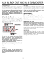
1
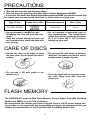
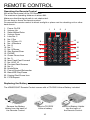
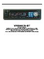
WELCOME!
Dear Customer,
CONGRATULATIONS. The VR500CS-BT MP3/CD Player with AM/FM Receiver,
USB Port and SD Card Slot, Electronic Anti-Shock (ESP) & Fold-down
Detachable Face, when used as described, will give you years of dependable
service in your car, truck, RV, or mini-van. We have taken numerous measures
in quality control to ensure that your product arrives in top condition and will
perform to your satisfaction. In the rare event that your VR500CS-BT MP3/CD
Player with AM/FM Receiver, USB Port and SD Card Slot, Electronic AntiShock (ESP) & Fold-down Detachable Face,contains a damaged or missing
item, does not perform as specified, requires warranty service, or you have
an installation problem, DO NOT RETURN THIS PRODUCT TO THE STORE.
PLEASE CALL OUR TOLL FREE NUMBER FROM THE U.S.A. AND CANADA
1-800-445-1797 and ask to speak with a member of our technical service
team; or submit your questions by e-mail to [email protected] and
a member of our technical service team will respond by e-mail to your questions. Our in-house technical service team will expedite delivery of your part,
advise you on installation, or help troubleshoot a problem with you. If your
product needs warranty service, our technical service team representative will
help you obtain the fastest remedy possible under the warranty.
CONTENTS
Contents .......................................................................................................... 1
Precautions...................................................................................................... 2
Care of Discs ................................................................................................... 2
Flash Memory .................................................................................................. 2
Notes on Installation........................................................................................ 3
Tools & Supplies .............................................................................................. 3
Before You Install............................................................................................. 4
Installation (DIN Front Mount)......................................................................... 5
Installation (Vehicle's Brackets) ....................................................................... 6
Microphone...................................................................................................... 7
Wiring Connections ......................................................................................... 8
Location of the Controls .................................................................................. 9
Remote Control ............................................................................................. 10
Basic Operation ............................................................................................. 11
Bluetooth .................................................................................................. 12-13
Radio Operation............................................................................................. 14
CD Operation................................................................................................. 15
MP3/WMA Operation (CD) ............................................................................ 16
USB/SD Card Operation................................................................................ 17
Search Modes for MP3 & WMA Files............................................................ 18
AUX IN, RCA, & Subwoofer Control.............................................................. 19
Specifications ................................................................................................ 20
Warranty......................................................................................................... 21
1
PRECAUTIONS
• This unit will only play the following discs.
• This unit does not play files that have Digital Rights Management(DRM).
• If you have files that have Digital Rights Management(DRM) you should consult with
the vendor that you purchased files from for instructions on proper use.
Type of disc
Label on the disc
Recorded material
Size of disc
Audio only
12 cm
CD, MP3, & WMA
• Do not attempt to modify the unit.
• Modifying the unit will void the warranty.
• Stop the vehicle before carrying out
any operation that could interfere with
your driving.
• Do not operate in extremely high or
low temperatures. The temperature
inside the vehicle should be between
32º F (0º C) and 100º F (37º C) before
turning on your unit.
CARE OF DISCS
• Handle the disc by its edge to keep
the disc clean. Do not touch the disc’s
surface.
• Do not use CDs with labels or stickers
attached. The label may leave a sticky
residue when it begins to peel.
• Do not use a CD with paste or ink
residue on it.
• Clean the discs with an optional cleaning cloth. Wipe each disc from the
center out.
FLASH MEMORY
The VR500CS-BT supports USB Flash Memory, Secure Digital Card (SD) and Multi
Media Card (MMC) of up to 1GB of memory.
We recommend you format your Flash Drive/SD Card in FAT32 format before saving any files. If you experience any compatibility problems, we recommend that you
contact the manufacturer of the Flash Drive/SD Card/Multi Media Card.
2
NOTES ON INSTALLATION
• Disconnect negative battery terminal before starting installation. Consult the vehicle’s owner’s manual for proper instruction.
• The unit is designed for a 12Volt DC negative ground operation system only. Before
installing the unit, confirm that your vehicle is a 12Volt DC negative ground system.
• Be sure to connect the color coded leads according to the diagram. Incorrect connections may cause the unit to malfunction or damage the vehicle’s electrical system.
• Be sure to connect the negative (-) speaker leads to the negative (-) speaker terminal. Never connect negative (-) speaker leads to chassis ground.
• The unit is only designed for use with 4 speakers. Do not combine output for use
with 2 speakers. Do not ground negative speaker leads to the chassis ground.
• Make sure all the connections are completely correct before turning on your unit.
• When replacing the fuse(s), the replacement must be of the same amperage as
shown on the fuse holder.
• Do not block vents or heater panels. Blocking them will cause heat to build up inside and may result in fire.
• After completing the installation and before operating the unit, reconnect the battery. Then press the (RES) button with a pointed object, such as a ball-point pen to
set the unit to its initial status.
TOOLS FOR INSTALLATION
• The 2 removal keys are supplied for removing the old unit and replacing with the
“VR500CS-BT”.
The following tools and supplies may also be needed for the installation:
SUPPLIES
• Machine Screws
• Crimp Connectors
• 14 Gauge Wire for Power Connections
• 14-16 Gauge Speaker Wires
TOOLS
• Phillips Screw-drivers
• Wire Stripper
• Wire Cutter
• Hammer
• Pencil
• Electrical Tape
• Electric Drill
The above are NOT INCLUDED with the VR500CS-BT and must be purchased seperately.
3
BEFORE YOU INSTALL
Automotive audio equipment installations can be troublesome at times, even to the most
experienced of installation technicians.
If you are not confident working with electrical wiring, removing and re-installing interior
panels, carpeting, dashboards or other components of your vehicle, please call your dealer
in order to have the unit professionally installed.
IMPORTANT: Remove the two transport screws from the top of the unit before installing.
1. Remove the Old Unit from the Dashboard
A. Remove the outer trim frame.
DIN Front Mount Style
B. Insert the keys supplied with the old unit
into both sides of the unit as shown in figure below until they click. Pull to remove
the old unit from the dashboard.
DO NOT DISCONNECT WIRES AT THIS TIME!
2. Mark Polarity of the Speaker Wires
Marking the polarity of the speaker wires will make it easier to connect the existing
speakers to the DVD Head Unit.
Consult wiring diagram of existing head unit before disconnecting any wires. If a
wiring diagram is not available contact the manufacturer.
A. While the old unit is playing, disconnect the wires from one speaker.
B. Take a length of masking tape and
fold it around the wire so it forms a
flag.
C. On the masking tape mark the polarity of the speaker wires (+ & - ), as
well as left or right, and front or rear.
D. Double check that you marked the
first speaker correctly by checking
that the speaker wires are the same
at the head unit.
E. Repeat this procedure for all of the
speakers.
F. Mark the power, ground, and any other wires also.
4
INSTALLTION
DIN FRONT-MOUNT (Method A)
Bend the tabs
to secure the
Mounting Sleeve
in the dashboard.
1. Dashboard
After inserting the Mounting Sleeve
into the dashboard, select tabs on
top, bottom, and sides, then bend
them to secure the mounting sleeve
in the dash board.(Fig. 1)
3. Screw
2. Mounting
Sleeve
Fig. 1
Follow the diagram in Fig. 2
for installing the rear mounting
strap to the head unit. The rear
mounting strap will help keep
the head unit from moving
around inside the dashboard.
1. Dashboard
2. Nut (5mm)
3. Spring washer
4. Screw (5 x 25mm)
5. Screw
6. Strap
7. Plain washer
Fig. 2
Insert fingers into the groove in the front of frame to remove it.
Insert the keys supplied with the unit in
the grooves on both sides. The unit can
be installed or removed from the dashboard using these keys.(Fig. 3)
Fig. 3
5
INSTALLATION
DIN REAR-MOUNT (Method B)
Installation using the screw holes on both sides of the unit.
1. Screw holes on the side of the unit.
2. Screws. Use either truss screws (5 x
8mm) or flush surface screws (4 x 8mm),
depending on the shape of the screw
holes in the bracket.
3. Vehicle’s Factory Mounting Bracket
4. Dashboard or Console
5. Hook (Remove this part)
Note: The mounting sleeve, outer trim
ring, and the mounting strap are not used
for this method of installation.
PARTS
2 Keys
1 Hex Nut
1 Mounting Sleeve (not shown)
2 Lock Washers
1 Sheet Metal Screw
1 Metal Support Strap
2 Flat Washers
1 Mounting Bolt
1 Faceplate Case
1 1/8" Stereo Cable
1 Remote Control
1 External Microphone (not
shown)
6
INSTALLATION
MICROPHONES
The VR500CS-BT has the ability to use two microphones. One microphone is built-in,
the other is a remote microphone.
NOTE: IT IS ALWAYS BEST TO INSTALL THE REMOTE MICROPHONE USING THE REAR “MIC
IN” JACK DURING THE INITAL INSTALLATION.
Built-In Microphone
The built-in microphone is located on the front left side of the unit. There is no setup required for this microphone and it is tuned to pick-up the voices of the front and rear seat
passengers.
Built-In Microphone (not visible)
Rear Microphone Jack
The suppled microphone shall be used to ensure the sound quality of the driver’s voice.
Installation
The rear microphone jack is located on the rear of the unit. Insert the plug of the supplied
microphone into the microphone jack. Route the microphone and wire to the driver’s side
sun visor, rear view mirror, or other area near the driver.
Setting the Microphone Volume
1. Press the “PHONE” button.
2. Press and hold the Volume Knob until
you see “OUT NUM” on the LCD
3. Press the Volume Knob to cycle through
the menu to “TEL”.
4. Rotate the Volume Knob to set the volume of the microphone.
7
WIRING CONNECTIONS
Make sure you have good chassis ground. A good ground connection will eliminate
most electrical noise problems. A good chassis ground requires a tight connection to
the vehicle’s metal chassis. The area around the ground connection should be clean,
bare metal without rust, paint, plastic, dust, or dirt for a good electrical connection.
Speaker Wiring Notes
Follow the above wiring diagram to install
the head unit with new or existing speakers.
• Never bridge or combine the speaker wire
outputs. When not using four speakers, use
electrical tape to tape the ends of the unused
speaker outputs to prevent a short circuit.
• This unit is designed for use with four (4)
speakers with an impedance between 4
Ohms to 8 Ohms.
• Never ground the negative speaker terminals to chassis ground.
• An impedance load of less than 4 Ohms
could damage the unit.
8
LOCATION OF THE CONTROLS
1
29
2
3
28
4 5
27
26 25 24 23 22
19 18 17 16 15
18. No. 9
19. No. 8
20. No. 7
21. UP 10/No. 6
22. Down 10/No.5
23. Random/ No. 4
24. No. 3
25. Intro/No. 2
26. Top/No.1
27. PHONE
28. Auxiliary Input
29. USB Port with Cover
30. Reset Button
31. A/E Switch
1. SD/MMC Card Slot
2. Liquid Crystal Display (LCD)
3. CD Slot
4. BND•ID3 / ||
5. Previous Track/Fast Reverse
6. Power
7. Next Track/Fast Forward
8. Mode/Mute
9. Volume/SEL/Enter
10. Eject
11. Answer/ Green Phone
12. Hang up/ Red Phone
13. Remove Faceplate
14. Subwoofer/Pound Symbol
15. Scan/Star Symbol
16. FPS/Repeat
17. Stereo/No. 0
30.
21 20
6 7 8
31.
9
9
10 11
14 13 12
REMOTE CONTROL
Operating the Remote Control
Aim at the front panel of the CD Receiver.
The maximum operating distance is about 6M.
Make sure that the signal path is not obstructed.
Do not drop or throw the remote control.
Do expose the remote control to direct sunlight or place next to a heating unit or other
heat source.
1. Power On/Off
2. Volume Up
3. Select/Menu/Enter
4. Volume Down
5. Intro/No. 2
6. No.1/Top
7. No. 5/Down 10
8. No. 4/Random
9. No. 8
10. No. 7
11. No. 0/Stereo
12. Star Symbol/Scan
13. PHONE
14. Green Phone Icon
15. No. 3
16. Next Track/Fast Forward
17. No. 6/UP 10
18. Previous/Fast Reverse
19. No. 9
20. Mode/Mute
21. Pound Symbol/Subwoofer
22. Band/ID3/Play/Pause
23. Display/Red Phone Icon
24. F/PS/Repeat
1
6
8
10
3
4
5
15
7
17
9
19
11
21
13
23
16
18
20
22
12
14
2
24
Replacing the Battery
The VR500CS-BT Remote Control comes with a CR-2025 Lithium Battery included.
Remove the Battery
Holder from the back of
the Remote Control.
Insert a CR-2025
Lithium battery.
10
Insert the Battery Holder
into the back of
the Remote Control.
BASIC OPERATION
1. Tuning the Unit On / Off
available.
Press any Button to turn the unit on, the display will show a message WELCOME to indicate it is ready for use. Press the POWER
button for 2 seconds to turn the unit off.
8. Treble
Press Volume Knob until the display shows
“TRE”. Use the Volume Knob to adjust.
When DSP is ON, treble control is not available.
2. Mode Selection
Press the BAND Button to select Radio
Mode. Press and hold the MOD/MUT Button to cycle the Play Mode between AUX,
RADIO and CD PLAY.
Note: USB mode or memory card mode will
only be displayed when a USB flash memory or SD Card is inserted.
9. Balance
Press Volume Knob four times and the display shows “BAL”, then use the Volume
Knob to adjust the balance between the left
& right speakers.
10. Fader
3. Loudness Control (head unit only)
Press Volume Knob five times and the display shows “FAD”, then use the Volume
Knob to adjust the balance between the
front & rear speakers.
Press and hold the Volume Knob for 2 seconds, then press the Volume Knob repeatedly to cycle through to “LOUD OFF”. Then
rotate the Volume Knob to turn to “LOUD
ON” for loudness to take effect.
11. Clock
The time clock can be set anytime when
the power is on. Press the DISP Button and
then press and hold DISP Button for 3 seconds, the time will blink on the display.
1. Press the VOL + Button to adjust the hour.
2. Press the VOL - Button to adjust the minute.
3. Press the DISP Button again or leave the
unit idle for new setting to effect. Press the
DISP Button anytime to view the time clock
display.
4. Subwoofer Control
Press SUB/# Button on the front panel, or
press the #/SUB Button on the remote control to turn the subwoofer ON or OFF.
The unit must have an external amplifier installed to drive the subwoofer.
5. Mute Control
Press and hold the MOD/MUT Button to
mute the radio. Press and hold again to
cancel. Note: If you press this button but
do not hold it, it will change to another play
mode.
12. Preset Beep Sound Off
1. Press the Volume Knob for 2 Seconds.
The display will show “DSP OFF”, then
press the Volume Knob repeatedly until the
display shows “BEEP OFF”. Use the Volume Knob to select “BEEP OFF” or “BEEP
ON”, then leave the unit idle for setting to
take effect.
6. Volume
Use the Volume Knob to adjust the volume
level. The display shows VOL 00 to VOL 47.
The larger the number, the higher the volume level.
13. Preset Equalizer Function
7. Bass
Press and hold the Volume Knob for 2 seconds, the display will show “EQ OFF”. Press
the Volume Knob to choose the EQ sound
effect desired.
Press the Volume Knob until the display
shows “BAS”. Use the Volume Knob to adjust. When DSP is ON, bass control is not
11
BLUETOOTH CONNECTION
Before Connecting
quick reference.
Turn the VR500CS-BT ON, then turn your
cell phone’s Bluetooth Function ON.
5. Answering a Call
When there is an incoming phone call, press
the GREEN PHONE Button on the front
panel or on the remote control to receive
the call through your car radio.
1. Pairing
1. Press the “PHONE” button.
2. Press and hold the Volume Knob until
you see “DISP OFF”,
3. Press the Volume Knob repeatedly to
cycle through to “PAIRING”.
4. Press and hold the Volume Knob until the
word “PAIRING” blinks on the display,
5. Run the Bluetooth search and connect
function on your cell phone.
6. VR500CS-BT will be shown on your cell
phone’s list of available connections. Select
the VR500CS-BT to connect the cell phone
with the VR500CS-BT.
When you are asked for a connection password, please input “0000” in your cellphone
to finish the pairing.
The Bluetooth icon and the word “PHONE”
will be shown on the VR500CS-BT’s LCD
indicating that the Bluetooth function is active and ready to use.
6. Ending a Call
When you have finished or wish to ignore a
call, press the Red “PHONE” Button either
on the Faceplate or on the remote control
to hang up.
7. Dialing with the Faceplate
When you want to dial a call from the front
panel of the radio, press the “PHONE” Button on the front panel. Press Buttons 1-0 to
dial the telephone number you wish to call.
Press the Green PHONE Button to activate
the call.
8. Dialing on the Remote Control
To make a call dialing with the remote control, press the “PHONE” Button on the remote. Press Buttons 1-0 on the remote to
dial the telephone number you wish to call.
Press the Green PHONE Button to activate
the call.
2. Ring Volume
1. Press the “PHONE” Button.
2. Press and hold the Volume Knob until
you see “FIND NUM”.
3. Then press the Volume Knob to cycle
through until “RING” appears. You can adjust the incoming call volume from “0”-”47”.
The radio will ring in the midst of song playing if there is any incoming phone call.
9. Recently Dialed Numbers
After connecting with cell phone;
1. Press the “PHONE” button.
2. Press and hold the Volume Knob until
you see “OUT NUM”.
3. Press and hold the Volume Knob and the
display will show the most recently dialed
number.
4. Rotate the Volume Knob to choose
among the 10 recently dialed numbers.
5. Press the Green “Phone” button to dial
the displayed number.
Alternative:
1. Press the “PHONE” button;
2. Press the Green Phone button;
3. The most recent dialled number will be
shown. Rotate the volume knob to view
the recent 10 dialed numbers. Press Green
Phone button to make call.
3. Telephone Volume
1. Press the “PHONE” Button.
2. Press and hold the Volume Knob until
you see “FIND NUM”.
3. Then press the Volume Knob to cycle
through until “TEL” appears. You can adjust
the telephone volume from “0”-”47”. The
larger the number, the louder the speaker
volume during the call.
4. Incoming Call Display
When there is an incoming call the LCD Display will blink the incoming number for your
12
BLUETOOTH CONNECTION
Knob to cycle through to “DIS CONN”.
Press and hold to disconnect the current
phone call so that you can connect with another call.
10. Recently Received Calls
After connecting with cell phone;
1. Press the “PHONE” button.
2. Press and hold the Volume Knob until you
see “OUT NUM”, then press the Volume
Knob until the display shows “IN NUM”.
3. Press and hold the Volume Knob and the
display will show the most recent received
call.
4. Rotate the Volume Knob to choose
among the 10 recent received numbers.
5. Press the Green “Phone” button to dial
the displayed number.
14. Ringtones
1. Press the “PHONE” button.
2. Press and hold the Volume Knob until
you see “OUT NUM”.
3. Then press the Volume Knob to cycle
through to “MELODY”.
4. Press and hold the Volume Knob and the
display will show MELODY 1.
5. Rotate the Volume Knob to choose from
MELODY 1 to 6 as different incoming music
tone in the car radio.
6. Press and hold the Volume Knob to
confirm after your desired Ringtone is displayed.
11. Speed Dial
You can save up to 10 phone numbers in
memory for Speed Dialing.
1. Press the “PHONE” button.
2. Press and hold the Volume Knob until
you see “OUT NUM”.
3. Next press the Volume Knob to cycle
through to “ADD NUM”.
4. Press and hold the Volume Knob and the
display will show “NAME *”.
5. Use the Volume Knob to choose letters
to compose name of up to 16 characters.
Press and hold Volume Knob to confirm.
6. The display will show “NUMBER *”. Use
the number buttons on the faceplate or the
remote control to enter a telephone number
of up to 32 digits.
15. Auto Re-Connect
This unit has an “Auto Re-Connect Function”. In case the connected cellphone is
out of range (e.g. the user leaves the car for
lunch), the unit will automatically connect
with the cell phone upon returning so that
you do not have to re-set the connection.
16. A2DP Stereo Transfer
The A2DP function is for listening to music on the VR500CS-BT via Bluetooth from
your cell phone. Play the music in the cellphone, then choose the option of “play via
bluetooth” in the cellphone.
Then press the MODE button in the radio
until the display shows “A2DP”. Note: A2DP
mode will only be displayed when you have
activated the A2DP function on your cellphone.
You can now listen to the music from the
cellphone through the car speakers.
12. Speed Dialing a Phone Number
1. Press the “PHONE” button.
2. Press and hold the Volume Knob until
you see “OUT NUM”.
3. Then press the Volume Knob to cycle
through to “FIND NUM”.
4. Press and hold the Volume Knob and the
display will show your saved name.
5. Use the Volume Knob to choose the
name and press the Green “PHONE” Button to call someone easily.
NOTE: It’s highly recommended that A2DP
mode should not be used simultaneously
with PHONE mode. Please quit A2DP mode
before attempting to make a phone call, unexpected results may occur, depending on
different cellphone models.
13. Disconnecting the Phone
Press and hold the Volume Knob until you
see “OUT NUM”, then press the Volume
13
RADIO OPERATION
1. Choose Radio Band
5. Save Your Preset Stations
Press the BND•ID3 Button anytime to access the radio function.
The unit comes with five bands - three FM
(FM1, FM2, and FM3) and two AM (AM1 and
AM2) Band selects. Each of the five bands
can store up to six preset stations, for a total of 30 preset memory stations.
NOTE: To change the receiving range from
USA to Europe, remove the faceplate and
move the switch marked “A-E” to the appropriate region.
There are six numbered preset buttons
which can store and recall stations for each
band. While listening to a radio station, press
and hold one of the buttons numbered 1-6
until you hear a beep. That button is now
the pre-set button for that station.
6. Automatic Store/Preset Scan
A. Automatic Scan & Store
While listening to the FM Radio, press and
hold the F/PS Button for more than 3 seconds. The receiver will automatically scan
and save stations to one of the FM Bands.
While listening to the AM Radio, press and
hold the F/PS Button for more than 3 seconds. The receiver will automatically scan
and save stations to one of the AM Bands.
2. Radio Tune / Seek Function
In Radio Mode, press Seek +/- Button to
manually adjust the radio frequency.
3. SEEK 1 & SEEK 2
Press and hold the Volume Knob until “DSP
OFF” is shown on the LCD, then press the
Volume Knob to cycle through the menu selections until “SEEK 1” is shown. Use the
Volume Knob to select either “SEEK 1” or
“SEEK 2”.
B. Reset Automatic Scan & Store
A. Seek 1
Press the F/PS Button once to scan all stations saved. In the FM Mode, all 3 FM Bands
will be scanned. In the AM Mode both of the
AM Bands will be scanned.
Press and hold the F/PS button for 3 seconds and the receiver will scan the radio
stations in your area, then save them over
the current pre-sets.
C. Scan Saved Stations
Press and hold the |<< or >>| Button for
more than 1 second. The radio will seek the
next strong and clear frequency station. Repeat to seek more stations in your listening
area with a strong signal.
B. Seek 2
Press and hold the |<< or >>| Button for
a radio station search. The search will not
cease until you release the button.
4. Mono/Stereo Reception Control
In FM radio mode, press the 0/ST button
on the front panel or on the remote control
to toggle between mono reception or stereo
reception. The display will show “MONO” or
“STEREO”.
Improvement of reception of distant stations can be done by selecting “MONO”
operation which may cut down some reception noise.
14
CD OPERATION
Electronic Skip Protection - 10 or 40
fast reverse. Disc will play normally when
the >>| or |<< Button is released.
seconds
Electronic Skip Protection is ideal for driving
on rough roads. Press the Volume Knob for 2
seconds. The display will show “DSP OFF”.
Press the Volume Knob again, “ESP10” will
be displayed indicating that Electronic Skip
Protection will be activated for 10 seconds.
With “ESP 10” on the display, use the Volume Knob to change the setting to “ESP
40”, indicating that Electronic Skip Protection for 40 seconds is activated. Leave the
unit idle for the new setting to take effect.
4. Play/Pause CD
On the Remote or Head Unit, press the
BND•ID3/>|| Button to pause the CD. Press
these buttons again to resume playback.
5. Resume All Tracks
On the Remote or Head Unit, press the
1/TOP Button to play the all the tracks
again. The first song on the CD will be
played.
1. Insert/Eject CD
6. Scanning Tracks
Insert a disc into the CD slot with label side
up. The disc will be automatically loaded
even if the radio is off or in the Radio Mode.
The word “LOAD” will blink on the display
and the CD will play automatically. Press
the EJECT Button to eject the disc from the
slot. If the disc is not removed from the slot
within 5 seconds, it will automatically be
loaded into the slot again. When the disc is
ejected and removed, the unit will automatically switch to Radio Mode.
On the Remote or Head Unit, press the
INT/2 Button to play the first 10 seconds of
each track. Press this button again to resume playback.
7. Repeat
On the Remote or Head Unit, press the
FPS/RPT Button to repeat the same track
continuously. “RPT ON” will appear on the
display. Press this button again to cancel
the repeat function.
2. Multi-Session CD Reading
8. Random
This unit can read multi-session CDs.
The multi-session reading will be activated
automatically if the player detects a file that
is written in multi-session format. Press and
hold the Volume Knob until “DSP OFF” is
shown on the LCD, then press the Volume
Knob to cycle through the menu selections
until “MULT OFF” is shown. Use the Volume Knob to choose “MULT ON” or “MULT
OFF”. The default is MULT OFF.
On the Remote or Head Unit, press the
RDM/4 Button to play all the tracks in random order. “RDM ON” will appear on the
display. Press this button again to stop random play.
3. Selecting Tracks
On the Remote or Head Unit, press the >>|
Button to advance CD to the next track.
Track numbers will be shown on the display.
Press and hold >>| Button to fast forward.
Press the |<< Button to go to a previous
track. Track numbers will be shown on the
display. Press and hold the |<< Button to
15
MP3/WMA FILES ON CDs
1. Insert/Eject CD
5. Resume All Tracks
Insert a disc with MP3 and/or WMA files into
the CD slot with label side up. The disc will
be automatically loaded into the unit, even
when the unit is off or in Radio Mode. The
word “MP3 DISC” will be displayed as the
CD is loaded. The first file in the root folder
will be played. As the file is playing, “ROOT”
will be displayed first, then if there is any ID3
information available, it will be displayed as
the file is playing. Press the EJECT Button
to eject the disc from the slot. If the disc
is not removed from the slot within 5 seconds, it will automatically be loaded into the
slot again. When the disc is ejected and removed, the unit will automatically switch to
Radio Mode.
On the Remote or Head Unit, press the
1/TOP Button to play the all the tracks
again. The first song on the CD will be
played.
6. Scanning Tracks
On the Remote or Head Unit, press the
2/INT Button to play the first 10 seconds
of each track. Press this button again to
resume playback.
7. Repeat
On the Remote or Head Unit, press the
F/PS/RPT Button to repeat the same
track continuously. “RPT ON” will appear
on the display. Press this button again to
stop repeating tracks
2. Multi-Session CD Reading
This unit reads multi-session CDs.
The multi-session reading will be activated
automatically if the player detects a file that
is written in multi-session format. Press and
hold the Volume Knob until “DSP OFF” is
shown on the LCD, then press the Volume
Knob to cycle through the menu selections
until “MULT OFF” is shown. Use the Volume Knob to choose “MULT ON” or “MULT
OFF”. The default is MULT OFF .
8. Random
On the Remote or Head Unit, press the
4/RDM Button to play all the tracks in random order. “RDM ON” will appear on the
display. Press this button again to stop
random play.
9. UP 10
Press the 6/UP10 Button to advance 10
tracks at a time.
3. Selecting Tracks
10. DN 10
Remote or Head Unit, press the >>| Button to advance CD to the next track. Track
numbers will be shown on the display. Press
and hold >>| to fast forward.
Press the |<< Button to go to a previous
track. Track numbers will be shown on the
display. Press and hold the |<< Button to
fast reverse. Disc will play normally when
the >>| or |<< Button is released.
Press the 5/DN10 Button to go back 10
tracks at a time.
4. Play/ Pause CD
On the Remote or Head Unit, press the
“BND•ID3” button to pause the CD. Press
this button again to resume playback.
16
USB/SD/MMC CARD OPERATION
USB Flash Memory
4. Scanning Tracks
To play MP3 / W MA files from a USB flash
memory, insert a USB flash memory into the
USB port on the left side of the unit. The
unit will start playing MP3 / W MA files on the
USB flash memory automatically. Or press
the MODE Button to select USB after pressing POWER Button to turn on the unit.
On the Remote or Head Unit, press the
2 / I NT Button to play the first 10 seconds
of each track. Press this button again to
resume playback.
5. Repeat
On the Remote or Head Unit, press the
F/PS / R PT Button to repeat the same
track continuously. “RPT ON” will appear
on the display. Press this button again to
stop repeating.
SD/MMC Card
To play MP3 / W MA files from a SD/MMC
Card, insert a SD/MMC Card into the SD
Card Slot on the left side of the unit. The
unit will start playing MP3 / W MA files on the
SD/MMC Card memory automatically. Or
press the MODE Button to select SD/MMC
Card after pressing POWER Button to turn
on the unit.
6. Random
On the Remote or Head Unit, press the
4 / RDM Button to play all the tracks in
random order. “RDM ON” will appear on
the display. Press this button again to
stop random play.
1. Play / Pause
When playing MP3 / W MA in the USB drive,
press the “BND-ID3” Button to pause playback. press the Button again to restore.
7. UP 10
Press the 6 /UP10 Button to advance 10
tracks at a time.
2. Selecting Tracks
8. DN 10
If the MP3/WMA files are stored in folders on
the USB drive or SD Card, the unit will start
by playing the first song in the first folder.
After playing all the files sequentially in the
first folder, the unit will play sequentially all
of the files in the next folder. The unit will
continue playing through all of the folders
on the USB drive or SD Card in this manner.
If the USB drive or SD Card has loose files
and folders containing files, it will play the
loose files sequentially, then it will play the
files in the folders sequentially.
The 5/DN10 and 6 / UP10 Buttons are used
to advance ten tracks at a time or go back
ten tracks at a time.
Press the 5 /DN10 Button to go back 10
tracks at a time.
3. Resume All Tracks
On the Remote or Head Unit, press the
1/ TOP Button to play the all the tracks
again. The first song on the CD will be
played.
17
SEARCH MODES FOR MP3/WMA FILES
begin to play.
Search Modes
Electronic Skip Protection - 120 Sec-
There are 4 search modes to help find your
favorite MP3 & WMA tracks. The search
modes only work with MP3/WMA CDs,
USB flash memory, and SD Cards with
MP3/WMA files. The search modes do not
work with any other file types on CDs or
USB flash memory.
onds
Electronic Skip Protection is ideal for driving
on rough roads. Electronic Skip Protection
for CD (that contains MP3 or WMA files) is
a default feature. Please note that this feature support the CD with Songs encoded at
96Kb/s and 32000Hz.
For songs encoded in higher quality, the
anti-shock duration will decrease proportionally to the file size.
1. Simple Track Search
Press the |<< or >>| Button to go to the next
track or previous track. Press the Number
5 button to go back 10 tracks at once or
press the Number 6 button to advance 10
tracks at once.
2. Track Search
Press the F/PS Button and the display will
show “TRK SCH”. Press the Volume Knob
so that “TRK” will blink on the display.
Then use the Volume Knob to choose your
desired track and press the Volume Knob
again to confirm the selection. The selected
track will be searched for and then played.
3. File Search
Press the F/PS Button twice and the display
will show “FILE SCH”. Press the Volume
Knob to enter the root folder of the disc.
Use the Volume Knob to choose a folder
in the root folder, then press the Volume
Knob to confirm. The selected folder will be
opened.
4. Character Search
Press the F/PS Button three times and the
display will show “CHAR SCH”. This is for
files by file names. Press the Volume Knob
and the first character will blink on the display.
Use the Volume Knob to change the character. Press the SEL button once to confirm the character entered and advance to
the next character. After you have input the
name, press and hold the Volume Knob to
confirm. The song nearest alphabetically to
the name input will be found and then
18
AUX IN, RCA OUT, MIC IN, & SUBWOOFER
1. RCA Output
ID3 TAG
The RCA Output Jacks are on the back of
the unit. (Refer to Wiring Diagram) This output is for connecting an amplifier, equalizer,
or other audio componement that requires
a pre-amp out connection. (Red = Right,
White = Left) Follow the manufacturers instructions for the audio component that you
are connecting.
If an MP3 file has ID3 Tag information, it will
be displayed on the LCD. If there is no ID3
Tag information, nothing will shown on LCD.
Press the BND/ID3 button anytime to view
the ID3 information of the song.
MAINTENANCE
Cleaning the Unit
Do not use any liquids to clean this unit.
Do not use petroleum distillates to clean
this unit.
Use a clean, dry cloth to clean this unit.
2. Sub Woofer Output
The Sub Woofer Output Jack is on the back
of the unit. (Refer to Wiring Diagram) This
output is for connecting an amplifier, that
requires a pre-amp out connection. (Red =
Right, White = Left)
Replacing the Fuse
Make sure the amperage matches the specified value when replacing the fuse(s). If the
fuse is bad, check the power connection
and replace the fuse with a new one. If the
same problem occurs, this might indicate a
malfunction within the unit.
WARNING
When replacing a fuse, do not use a fuse
with a higher amperage rating than the fuse
originally supplied to your unit, otherwise
damage will result to your unit.
To use the sub woofer Jack press SUB/#
Button on the front panel, or press the #/
SUB Button on the remote control to turn
the Sub Woofer Jack ON or OFF.
The unit must have an external amplifier installed to drive the subwoofer.
Follow the manufacturers instructions for
the audio component that you are connecting.
3. Mic In
The Mic In jack on the rear of the unit is
for the supplied external microphone. The
external microphone is for the driver of the
vehicle.
19
Specifications
GENERAL
Operating Power ................................................................... 12 Volts DC, Negative Ground
Output Wiring ............................................................Designed for using four speakers only
Maximum Output Power ..................................................................................... 4x45 Watts
RMS Output Power ............................................................................................. 4x21 Watts
RCA line out .............................................................................. low-level outputs - 1000MV
Output Impedance ...........................................................Compatible 4 to 8 Ohm Speakers
Fuses ....................................................................................................... 1 amp and 10 amp
Dimensions................................................................... 178mm(W) x 178mm(D) x 51mm (H)
Weight ......................................................................................................................... 2.3 Kg
CD PLAYER
Signal / Noise Ratio.....................................................................................................>80dB
Frequency Response ...................................................................................... 20 Hz~20KHz
Channel Separation.....................................................................................................>50dB
D / A Converter............................................................................................................. 16 Bit
FM TUNER
Tuning Range...................................... (USA) - 87.5 - 107.9MHz, (Europe) - 87.5 - 108 MHz
FM Sensitivity ..............................................................................................................12dBu
Stereo Separation @ 1 Khz............................................................................................35dB
AM TUNER
Tuning Range......................................... (USA) -- 530-1710 KHz, (Europe) -- 522-1620 KHz
Am Sensitivity..............................................................................................................30dBu
20
Limited Warranty
VIRTUAL REALITY VIDEO LABS® products are designed and manufactured to provide a high level of troublefree performance. VIRTUAL REALITY VIDEO LABS® warrants, to the original purchaser, that its products are
free from defects in material and workmanship for 30 days from the date of original purchase, as part of our
commitment to product excellence. VIRTUAL REALITY VIDEO LABS®HUKVYP[ZHMÄSPH[LZYV\[PULS`PTWYV]LZ
the designs, materials or production methods of its existing products. Because it is impractical to publicize
all changes in every product, we reserve the right to make such changes without notice.
CONDITIONS OF WARRANTY:
If during the 30 day warranty period your new product is found to be defective, VIRTUAL REALITY VIDEO
LABS® will repair such defect, or replace the product, without charge for parts or labor subject to the following conditions:
1. All repairs must be performed by VIRTUAL REALITY VIDEO LABS® HUKVY P[Z HMÄSPH[LZ PU ,H[VU[V^U
New Jersey.
2. The equipment must not have been altered or been damaged through negligence, accident, or improper
operation.
3. The replacement of parts are exempted from this warranty when replacement is necessary due to normal
wear and tear.
4. All warranty claims must be accompanied by a copy of the sales receipt or bill of sale.
5. Repair or replacement parts supplied by VIRTUAL REALITY VIDEO LABS® under this warranty are protected only
for the unexpired portion of the original warranty.
6. In the case of car stereos, this warranty does not extend to the elimination of car static or motor noise;
correction of antenna problems; costs incurred for the removal or reinstallation of the product; damage to
tapes, speakers, accessories or car electrical systems.
7. VIRTUAL REALITY VIDEO LABS® will not be responsible for any charge incurred for installation.
OWNER’S RESPONSIBILITIES:
VIRTUAL REALITY VIDEO LABS® will make every effort to provide warranty service within a reasonable
period of time.
SHOULD YOU HAVE ANY QUESTIONS ABOUT SERVICE RECEIVED, OR IF YOU WOULD LIKE ASSISTANCE IN OBTAINING SERVICE, PLEASE CALL TOLL FREE 1-800-445-1797, 8:30am - 4:30pm EST.
In order to provide you with the proper warranty service, we request that you adhere to the following procedure:
1. Include a copy of your sales receipt or bill of sale with your unit when it is returned for warranty service.
2. If it is necessary to return your product for service, please return it securely packed, preferably in the original shipping carton, and freight and insurance prepaid to the following address: VIRTUAL REALITY VIDEO
LABS, Service Department, 41 James Way, Eatontown, New Jersey 07724.
3. Please include a detailed explanation of the problem you are having.
4. If your product is found by VIRTUAL REALITY VIDEO LABS® to have a defect in material or workmanship,
within the warranty period, it will be repaired or replaced at no charge and returned to you prepaid. Where
permitted by Iaw VIRTUAL REALITY VIDEO LABS® liability shall be limited to that set forth in this warranty.
This warranty shall be the exclusive remedy of the purchaser.
VIRTUAL REALITY VIDEO LABS® makes no other warranty of any kind, expressed or implied; and all implied
warranties, are hereby disclaimed by VIRTUAL REALITY VIDEO LABS® and excluded from this warranty,
VIRTUAL REALITY VIDEO LABS®HUKVYP[ZHMÄSPH[LZ[OLTHU\MHJ[\YLYKPZ[YPI\[VYHUKZLSSLYZOHSSUV[IL
liable for any injury, loss or damage, incidental or consequential, arising out of the use or intended use of
the product.
©2006 Virtual Reality Sound Labs® All designs, logos and images are the exclusive property of
Virtual Reality Sound Labs® and/or its affiliates. All rights reserved. 100606 Printed in China 00000