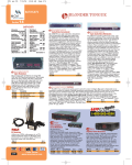
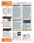
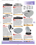
1
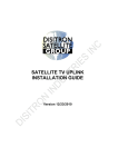
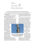
Field Operations Manual Chapter Four - Field Standards Confidential Page 26 9/8/2006 I. Field Installation Standards The following provides the details that are to be complied with for every installation. General Standards • Completed installation must be clean, orderly, traceable and functional. • Speaker mounts must be plumb, straight and solid. • Equipment racks must be clean and wires properly tied, bundled and numbered. • All interconnect wiring must be correctly labeled. • All terminations, connectors, plugs and terminal blocks must be properly soldered with any exposed wires individually protected by heat shrink. • All equipment must be labeled for ease of operation. • Entire system installation must be tested and verified for functionality against scope of work. • Any customer punch list items relating to the DMX installation or field service call must be addressed prior to customer’s completion deadline. • All audio components must be adjusted, balanced and volume levels set in accordance with DMX’s direction. • All precautions will be taken to insure that during the installation none of the customer’s property, furniture or fixtures is damaged. • Store personnel will be trained on operation and preventative maintenance of system prior to customer’s sign off. Confidential Page 27 9/8/2006 Speakers • All surface speakers within a zone will be mounted at the same height. • All surface speakers within a zone will be mounted on the same throw axis. • All surface speakers in an installation will be mounted either vertically or horizontally with no combinations of the two (unless specifically called out in engineering details). • All wires for surface speakers are to be well hidden. • Ceiling speakers in suspended tile ceilings shall be supported from the ceiling grid by the appropriate tile bridge or rail support and seismic straps to structure in seismic areas. • All speakers installed in ceiling tile shall have neatly cut holes that are completely hidden by the grill. • All speakers installed in ceiling tile shall have the speaker mounted in the center of the tile unless conditions prohibit. • Ceiling tiles that have speakers installed in them are whole, no cracks or broken corners. • 70v speaker transformers shall have the unused stripped leads cut back to the insulating jacket to prevent shorting on each other, the speaker casing, or the back can. Neatly bundle and secure unused transformer leads. • Speakers shall be located as indicated on the drawings with minor changes not to exceed 12” horizontally if surface mounted, and one tile in any direction unless approved by DMX. Confidential Page 28 9/8/2006 Wiring • All wiring runs are to be concealed in ceiling and walls whenever possible. • Any wiring that is exposed must be as well hidden as possible: tight into corners or hidden by trim. All bends in wiring will be 90 degrees, and exposed wires must either run parallel or perpendicular to the floor. • Wires for a Head End shall not be run exposed down any wall. They shall be in the wall or in a wire management tray or chase. • Exposed wiring shall be attached to walls and ceiling by staples securely enough to avoid wire sagging. • All wiring that runs horizontally above drop tile ceiling shall be supported every 4 to 5 feet to protect the cable from the stress related to its own weight and resulting sag. • Cable shall not be tied to ceiling support system, sprinkler pipes or electrical conduit. • Wire dress at the head end shall have signal separation spacing observed. • Wires exiting a wall will have a trim plate. • Any retrofit installation shall have a new wiring infrastructure (all wiring except 110V mains) pulled. • All wiring will be run so that it’s kept at a safe distance from possible interference sources as specified in Appendix C “Cable Pulls”. Confidential Page 29 9/8/2006 Splicing • Types of lines that may be spliced with crimp connectors are speaker, line level, and volume control. • All splice connections (speaker, line level, volume control) shall be made with insulated crimp type connectors. • Types of lines that may not be spliced are microphone, data and coax runs. • Wire nuts are not to be used for any low voltage wiring. Confidential Page 30 9/8/2006 Terminations • All wires connected to equipment will have properly sized (wire and screw size) spade lugs crimped on with an appropriate crimp tool to eliminate frayed terminations. • When unbalanced line level cables are stripped, the shield will be covered with an insulating material such as the jacket of the wire, shield tubing or heat shrink. • All audio connections will be consistent with wiring schemes as indicated in Appendix A, “Audio Connections”. • All RF and BNC terminations will be made as specified in Appendix B, “Coaxial Cable”. Confidential Page 31 9/8/2006 Labeling • All equipment shall be labeled in such a way as to indicate the level settings, source input names and zone covered. • All labels will be made with a Brother Labeler or similar quality thermal labeler. Dymo or embossed type labels are not to be used. • All wires should be labeled as indicated on DMX plans (see Appendix C, Cable Pulls). If any changes are made in the field, it should be noted on the signed installation record and prints. Confidential Page 32 9/8/2006 Anchoring • All equipment, surface mounted or recessed, that is supported by the building structure shall be installed with the appropriate hardware that is rated for five times the weight of the equipment hung (see Appendix D, Hardware Schedule). • Any piece of equipment mounted to walls must have at least 50% of its attachment points going into studs or other solid structure. The other 50% of the mounting points may be mounted into hollow walls using hardware as specified in Appendix D. • Only anchors listed in Appendix D may be used for DMX installations and limited in use to the type of materials listed for each anchor. • Only aircraft rated cable or closed link chain may be used to suspend equipment from overhead. Open link chain may not be used in DMX installations. • The mounting surface shall have a sufficient rating to hold the anchored equipment. If needed, install an anchor backing plate to spread the load over a larger surface area. • Speakers and TV’s mounted in public areas shall not be hung lower than 7’ above the finished floor, unless specified by DMX. • In seismic areas a safety support tied to building structure will be required. • Screws on all equipment shall be snug and screwed into an anchor or box. Confidential Page 33 9/8/2006 Equipment Placement • All equipment is to be located as specified on the plans provided by DMX. • Head end equipment shall be installed in a safe and secure permanent location. • No equipment shall be placed directly on top of a DMX source player for proper ventilation (at least 1” clearance). • Volume control height must be between 4’ to 5’ if mounted to walls, unless otherwise specified by DMX. Whenever possible, volume controls must be recessed into walls. • Wall plates are to be installed straight and plumb with appropriate backing. • All volume controls are to be mounted at the same height unless specified otherwise by DMX. Confidential Page 34 9/8/2006 Equipment Racks/Assembly • Install all equipment and shelves in the proper locations as specified in plans provided by DMX. • Tighten all rack rail bolts to insure rail stability. • Install rear supports for deep or heavy equipment. • Install Panduit or other raceway for wire management, if needed • Install lacing bars for wire support to equipment if needed • If multiple racks, connect all racks with a common ground of at least 14 awg. to prevent floating rack ground. • If fans are required, utilize the provided cut out in the top of racks to save rails for equipment. • Provide grommet stripping on all knockouts used as cable entry to prevent cable scarring. • Place plans and ‘as built’ wiring diagram in pouch provided by DMX and attach to inside of rack to facilitate service work. Confidential Page 35 9/8/2006 Equipment Racks/Assembly - (continued) • Separate all cables by 6” in groups as follows: Mic Level nothing to -20dBm REF. (.775mV @ 600 Ohms) Line Level -20dBm to +30dBm Speaker Level +30dBm and up Video RF Cable, DMX Satellite Cable, Control, Timecode • All equipment racks must have a minimum wiring service loop of 5’ to facilitate servicing or changes to system. Confidential Page 36 9/8/2006 Electrical Make sure the electrician is aware of the following electrical requirements. If there is a conflict, notify DMX immediately. • Video and audio power should be 180 deg. out of phase. • If isolated ground is specified, use only iso-ground outlets and strips. • Twist all ground leads and then cap them. • Connect all AC outlets using fan out or star method ensuring a direct circuit connection from the supplying conductor to outlet itself. • The ground on outlets should always point down. • When switching AC, the hot leg should be switched, never neutral or ground. • If the AC is remotely switched, provide unswitched outlets for any control, test or technician gear. Confidential Page 37 9/8/2006 Satellite • All dishes must be assembled in compliance with the manufacturer’s instructions. • Dishes must be anchored using the Ballast Requirements described in section 4, page 44. • Dishes must be grounded to suitable building earth ground rod as per Section 810 of the National Electrical Code. • Antenna cable must never enter the building through a horizontal surface such as the roof. Existing conduit or cable access tubes may be used. If new roof penetration is required, work must be performed be a qualified roof contractor. • If a new hole into the building must be made, it should be made through a wall and closed with weatherproofing caulking. • Care must be taken when assembling the dish to ensure no penetration of the roof membrane. • All dishes must have a DMX logo decal applied in the field if not done at the factory. Confidential Page 38 9/8/2006 II. Testing Procedures The following testing procedures should be applied for every installation: ♦ All speaker zones shall be tested for impedance with a Goldline ZM-1 or like model. Note that all Volume Controls need to be set “wide open”. Insure that signal frequency sent is within Speaker Tolerances, i.e.…..1K Hz to Subwoofer will not work, should be 100 Hz. Impedance will be noted on IR. ♦ Line levels in rack shall be tested for proper phase using a Goldline Phase Checker or like model. ♦ All Speakers in System shall be tested for phase using a Goldline Phase Checker or like model. All DMX Installations that have “Commissioning” included in the Equipment List, Subcontract Agreement, or Scope of Work, will require that the following be performed in addition to the above steps. ♦ Balance gain structure to +4 dBu as per DMX FASST Requirements. 1. This level should be achieved after the source player. 2. Level should be consistent throughout entire system, up to the amplifier output. Note: This measurement should be performed with a good quality voltmeter. The meter should be rated for “True RMS”. ♦ EQ the system, as per DMX FASST Requirements 1. Insert Goldline Pink Noise Generator, or like model, into signal path. 2. Set Amplifier Output to reflect 94 dB in room being measured. Note: all VC’s should be wide open. 3. Measure room with Goldline Real Time Analyzer. Make adjustment to EQ Faders so that all frequencies are relatively flat. Note: Readings should be + or – 3 dB, they don’t have to be perfectly flat! 4. Remove Pink Noise Generator. Reinstall source/s and play customer’s content over system, i.e. Profusion X, DBS Receiver, etc. 5. Listen for “Bad Sound”, too much bass, very bright, etc. 6. Make “Fine Adjustments” by ear. 7. Ask for customer input as to the sound of the room. 8. Repeat steps 1&2. Take final measurement of room and save settings on RTA. 9. Replace source and complete commissioning note section of IR. DMX Reserves the right to inspect all installations as discussed in Section IV, page 50. Confidential Page 39 9/8/2006 III. Equipment for Sub-Contractors Required: - True RMS Multimeter Real Time Analyzer / SPL Meter Tone/Signal Generator (line level and mic level) Inductance Wand Impedance meter (bridge) Telephone butt set / Headphone amp Source material for test purposes Middle Atlantic Products TX-1 pin in torx security bit (recommend more than one) Thermal Labeler (i.e. Brother P-Touch) Phase/Polarity generator and Analyzer Soldering iron Heat gun Punch tool for 66 and 110 blocks Staple gun for wire Flush cutting dikes Coaxial crimper Wire stripper Jewelers screwdrivers Sheet rock saw Recommended expendables: - Wire ties 7” and 4” black and white - Closed end insulated crimp caps - Spade lug connectors - Terminal Strips - Self labeling wire labels - Staples - Grommets - Shrink wrap tubing - RCA, XLR, and ¼” connectors - Solder Recommended service stock: - Volume controls - Spare Amplifiers - 10 K pots - Microphones - Various Wire - Spare Speakers (surface and flush) Confidential Page 40 9/8/2006 IV. DBS Field Standards EQUIPMENT CHANNEL MASTER DISH DR RECIEVERS REMOTES TOOLS AND MISC. HARDWARE STANDARDS DBS SYSTEM OVERVIEW ANTENNA INSTALLATION AND ALIGNMENT MULTIPLE RECEIVER INSTALLATIONS Channel Master 1.0 Meter Dish • 1 meter receive only dish • Non-penetrating roof mount • KU band digital LNB • Vertical Polarity • Grounding point provided on mount. • Must have Line of site to Satellite. • Fully adjustable Az/El mounts. • Azimuth – Compass • Elevation – Inclinometer • Roof pad – 3/8 inch • Cable – RG-6 coax cable • 8.05 dB loss per 100 ft. @ 1450 MHz Frequency dependent Confidential Page 41 9/8/2006 DR 500 or DR200 Receivers Full CD Stereo quality Mono, Stereo and Digital outputs One Hundred plus channels available User and network programmable forced tuned events Troubleshooting Indicator lights 1. Stereo, Mono, SYNC, AUTH & LNB Power Remote Controls Standard Remote 2. Standard control functions 3. Able to troubleshoot with Customer Service DJ or ICX Remote 4. Standard control functions 5. Provides artist, album and title 6. Able to troubleshoot with Customer Service Confidential Page 42 9/8/2006 Tools & Misc. Hardware Compass Inclinometer Concrete blocks RG-6 Coax Cable F-connectors RG-6 crimp tool Wire cutters Socket wrench set Ladder Inverter and power pack Extension cord Splitters and inline amplifiers - Splitters – 3dB loss Recommend using a DC power passing or diode steered if more the one receiver - Must have a bandwidth of 950MHz – 1450MHz Hand drill and bits Silicone sealant RCA Cables Confidential Page 43 9/8/2006 Standards NEVER penetrate the roof!!! Try to hide dish from street view Always ground the dish. Always use required amount of ballast 8-12 32lb cap block Note condition of customer’s sound system. Give DMX Music welcome kit to customer Train customer on using their new system What This Means Additional time for installation Saves time in the long run with fewer service calls Customer satisfaction Confidential Page 44 9/8/2006 DBS System Overview Although the use of satellites, satellite dishes, and receivers may seem complex, the DMX/DBS service uses a highly sophisticated system that makes channel selection and local music programming easier and simpler than using a VCR. It also allows DMX to deliver music of unprecedented linearity, sonic precision, and exceptional fidelity. The DMX/DBS premiere digital audio service uses the following satellite technology: Satellite Uplink Facility ⎯ transmits music programming to the satellite through satellite dishes Satellite ⎯ relays the music programming signals to your satellite dish antenna DBS Satellite Dish Antenna ⎯ receives the music programming transmitted from the satellite and relays it to the DR500 Receiver. Your satellite dish can be as small as one meter and may be installed in various places on or around your location. The only constraint is that the satellite dish must be properly pointed at the satellite with no obstacles blocking the satellite signal. Confidential Page 45 9/8/2006 Once the DMX music programming is received at your location, your DR500 or DR200 Receiver and associated audio components take over. • COMSTREAM DR200 Digital Audio Receiver DIGITAL AUDIO Digital Audio Satellite Receiver ⎯ receives and decodes the digital audio programming information and sends it to your stereo amplifier system Additional receivers provide you with additional flexibility to create tailored music programs for multiple business environments that you can vary by the hour. Additional units can be integrated into your system at any time. • 1 2 4 5 6 7 8 9 0 Confidential 3 Remote Control device ⎯ allows you to control and program the DR500 Receiver and DBS system There are two available remote control types: the Standard remote, which is a basic remote control device, and the DJ, or ICX remote which provides additional programming information and functionality. Page 46 9/8/2006 Remote Control Units To select music channels remotely, you can use any DMX remote control unit. All remote control models have the following features: • Individual channel selection keys that allow you to move through the authorized channels one channel at a time either up or down • Preset channel selection key that allows you to enter special music programming information • Scan key that allows you to step through each authorized channel, each playing for five seconds • Mute function that allows you to turn the audio on and off • Last channel recall function that allows you to return to the previously selected channel To use either remote control unit, point it toward your DR500 or 200 Receiver and press the appropriate keys. The remote control units can be used at distances of up to 10 meters (32 feet) while you are directly in front of and in a straight line to the Receiver. Communication between the remote control and receiver will be impaired if there are obstructions blocking the transmission or if the remote control is not directed straight at the receiver. If the remote control fails to operate, refer to the manual for the respective receiver for troubleshooting tips. Confidential Page 47 9/8/2006 Antenna Installation and Alignment Satellite Dish Installer: Ground the RF input cable to the building grounding system as close as possible to the point of building entry. Refer to the National Electric Code (NEC) Article 820-40. The following steps describe the process to properly set up, position, and connect the antenna using the DR500 Receiver: 1. Determine the proper block converter and feed horn polarity adjustment for your area. 2. .Assemble the satellite dish antenna. 3. Locate the antenna in an area with an unobstructed line of sight to the satellite coordinates (azimuth and elevation) for your area. 4. For information relating to satellite location and coordinates, antenna alignment, and signal acquisition, contacts your nearest DMX office. 5. Pre-position the antenna to the correct azimuth and elevation coordinates by using a compass and inclinometer. 6. Pre-position the LNB to the indicated polarity setting. 7. Locate the DR500 Receiver within visual range of the antenna. 8. Connect a 75 ohm coaxial cable (RG-6, typical) from the output of the LNB to the Receiver RF IN connector. 9. Connect 120 VAC power to the DR500 Receiver – do not turn it on. 10. Place the receiver in signal strength mode by depressing the power, channel up, and channel down buttons simultaneously. Alternatively, this may be done with the remote control using Preset 180. The display reads nL, signifying it is not locked. 11. Channel 1 flashes on the front panel display indicating the receiver is muted 12. AUTH LED is Off unless the receiver is already authorized 13. SYNC LED is Off and remains so until the satellite is acquired 14. The signal strength level numbers are preceded by a minus sign (-) to differentiate them from a music channel number. Signal Quality readings vary from -00 (the strongest level) to approximately -80 (weakest level) before losing the satellite lock nL. 15. Rock the dish slowly from side to side and up/down around the nominal position. When the Satellite has been located, the display will read out a negative number representing signal strength and the Sync light will illuminate. Carefully move the dish to maximize signal, at which time the readout will be the least negative (closest to zero). Tighten the bolts and check that signal strength has not been disturbed by tightening the bolts. Confidential Page 48 9/8/2006 Connecting Multiple Receivers to One Antenna Multiple DR500 Receivers can be connected to one antenna. However, to avoid damage to either the antenna LNB and DR500 Receiver, the following items must be used: • Correct splitter(s) • Proper line amplifiers Line amplifiers may be required when using a signal splitter and/or when long coaxial cable runs are required from antenna to receiver. All splitters and line amplifiers should be rated for satellite IF processing with a minimum bandwidth of 950 MHz to 1450 MHz. Since power is delivered to the LNB and line amplifier by the DR500 Receiver (18 VDC via RF IN connector), splitters should have one DC power passing port, or be diode steered. Never connect via power passing splitters. Additionally, the receivers not delivering power to the LNB should have their LNB power output switched OFF using Preset 160, unless using diode steered splitters. Failure to do so may result in severe damage to the antenna LNB and the DR500 Receivers The line amplifier should be inserted just prior to the input of the splitter (not after the antenna LNB). For best performance line amplifiers are typically inserted every 150 feet. Recommended Equipment The following equipment is recommended when multiple receivers are connected to one antenna: IV. • High frequency splitters • Channel Master 2212IFD. Two port splitter, diode steered. Not necessary to disable LNB power from 2nd receiver. • Channel Master 2414IFD. Four port splitter, diode steered. Not necessary to disable LNB power from any receiver. • In-line satellite amplifier. Channel Master 5113IFD line amp. • Coaxial Cable. Maybe necessary to use RG-11 for longer runs, over 300’. Inspections DMX reserves the right to inspect all DMX jobs in progress or completed. DMX’s field inspections are intended to assure that all work performed meets the standards set forth in this manual and a project’s scope of work. If the field inspection determines that the work performed is not within DMX’s standards, DMX will provide the Sub-Contractor a detailed punch list in order to correct the disparity. If the Sub-Contractor cannot correct the discrepancies within 48 hours or the given customer deadline, they may incur the cost in correcting or completing the job. Confidential Page 49 9/8/2006