1
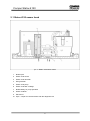
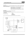
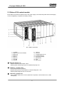
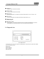
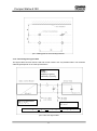
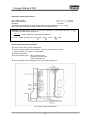
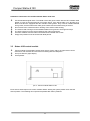
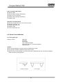
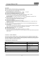
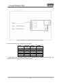
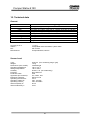
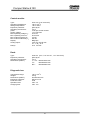
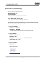
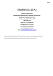
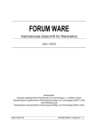
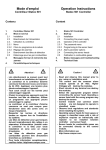
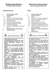
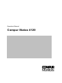
Operation Manual Compur Statox 4120 Compur Statox 4120 This document is subject to changes without notice. Regular updates can be viewed on our web site www.compur.com You are welcome to communicate any proposal how to improve this document to Compur Monitors. Copyright Compur Monitors GmbH & Co. KG Published by: Compur Monitors GmbH & Co. KG Weissenseestrasse 101 D-81539 München Tel. 0049 (0) 89 62038 268 Fax. 0049 (0) 89 62038 184 2 Compur Statox 4120 Contents Seite 1. 2. 2.1 2.2 2.3 2.4 3. Important notice The Statox 4120 System: Purpose of use and description 4 4 Statox 4120 sensor head Statox 4120 rack Statox 4120 control module Diagnostic box 5 6 8 9 Installation and electrical connections 10 Statox 4120 sensor head 10 3.1.1 Mounting 10 3.1.2 Connecting the signal cable 11 Statox 4120 rack Statox 4120 control module Switch positions of the sensor head pcb 13 14 15 Compur Statox 4120 operation 18 Start - up Alarm thresholds Detection mode Self test of the system Manually triggered self test of the system System failure 18 18 18 18 19 19 Trouble shooting 19 Using the diagnostic box 20 5.1.1 Operation and error codes of the diagnostic box 20 5.1.2 Status messages of the sensor head 21 Maintenance and calibration 22 Inspection Statox 4120 sensor head Sensor head calibration 22 23 6.2.1 Using span gas 23 6.2.2 Use ex-works calibration 24 3.1 3.2 3.3 3.4 4. 4.1 4.2 4.3 4.4 4.5 4.6 5. 5.1 6. 6.1 6.2 7. The maintenance request option 8. The option analog output inhibition 9. The option zero adjustment 10. Technical data 11. Accessories and spare parts Addendum: Declaration of conformity 3 25 28 29 30 32 34 Compur Statox 4120 1. Important notice Statox 4120 is an explosion proof system for the detection of toxic gases. It can be operated in hazardous areas classified division 1 and 2. Before installing and putting Statox into operation read and observe this manual! To operate the system safely, observe this manual carefully. It must be operated and maintained by qualified and authorised personnel. No other application than ambient air monitoring of the gas specified is authorised by the manufacturer. Safety guidelines Prior to connecting and installing the Statox 4120 system check if all any safety – relevant parameters of the system and its environment are in accordance with specifications and local regulations. If the Statox sensor head is installed in a potentially hazardous atmosphere the safety relevant parameters of the sensor head and the control module must be observed. Please use cable specified as recommended in this operation manual. Operating conditions must not exceed the specifications. The alarm relays of Statox 4120 are only safe to operate 24 V DC. Do not connect to mains. Maintenance work must be carried out by trained personnel only. Use exclusively original spare parts, accessories and consumables. If the safety guidelines are not observed, the Ex approval will be void! The instrument has to be inspected and serviced in regular intervals by trained personnel. For service or training contact your local Compur Monitors representative. The maximum maintenance interval should be 6 months. 2. The Statox 4120 system: Purpose of use and description Compur Statox 4120 is a stationary toxic gas detection system. It monitors continuously ambient atmosphere indoor and outdoor. It`s integrated self test provides maximum safety of operation. Two user - adjustable alarm thresholds A1 und A2 can be set to any value within the measuring range. It consists of these components: Statox 4120 sensor head Statox 4120 rack Statox 4120 control module Diagnostic box The Statox 4120 control module communicates a digital signal via a two-wire cable with the sensor head. It operates as power supply, alarm device and signal display. The system permanently checks itself for proper function and will alarm if any parameter is geting out of specifications. Sensor calibration and system fault diagnosis is easily achieved using the Statox portable diagnostic box. 4 Compur Statox 4120 2.1 Statox 4120 sensor head pic. 1: Statox 4120 sensor head 1 Bottom part 2 Statox 4120 sensor 3 Statox 4120 dust filter 4 Gas generator 5 Statox 4120 pump 6 Statox 4120 filter cartridge 7 Buffer battery for pump operation 8 Water container 9 Electronics 10 Opto - coupler for communication with the diagnostic box 5 Compur Statox 4120 pic. 2: Statox 4120 sensor head for Cl2 und ClO2 Operation principle Ambient air enters the sensor (2) by diffusion through an opening at the bottom. The sensor creates a current - signal proportional to the gas concentration. This signal is amplified, temperature compensated and linearised. As a digital signal it is transmitted to the control module. To protect the sensor from being poisoned by a high gas concentration, the Statox features a built – in air purge. This is activated when the gas concentration exceeds 95 % of the measuring range and stops when it has dropped below 80 %. The battery pack (7) buffers the energy demand of the built – in pump (5). It is on permanent trickle charge. The pump is activated in the protection mode and during the self test to purge the sensor and provide test gas from the gas generator (4) to the sensor. 2.2 Statox 4120 rack The Statox 4120 rack and the Statox 4120 control module provide the power supply for the sensor head. They are certified explosion proof [EEx ib] IIC. The rack must not be installed in certified areas! 6 Compur Statox 4120 Construction: The system consists of a 19“-4-HE rack with backplane and up to nine Statox 4120 control modules. Each Statox 4120 sensor head is communicating with one control module. The Statox 4120 rack is available in following designs: STATOX 4120 Rack ½ x 19“ for 4 Control modules STATOX 4120 Rack 19“ for 9 Control modules STATOX 4120 Rack 19“ for 9 Control modules / RFI shielded STATOX 4120 Desk case for 4 Control modules STATOX 4120 Desk case for 19“ Rack with 9 Control modules Connections: On the backplane (pic. 3) you find the following terminals: power supply 230 V/AC (115V/AC) Intrinsically safe terminals (signal cable, 22V/DC, 50mA) for data transmission and sensor head power supply. Analog outputs: 0-1V 4-20 mA Potential free relays: Pre-alarm A1 Main alarm A2 System alarm SF The A1 and A2 relay signal of the Statox 4120 control module is programmable. pic.3: Electrical connections 7 Compur Statox 4120 2.3 Statox 4120 control module Each Statox 4120 Control module has its own power supply. The intrinsically safe sensor head supply circuit is supplied by a separate secondary winding. pic.4: Statox 4120 Rack 1 2 3 4 5 6 7 8 19“ Rack Statox 4120 control module Button A2 Button A1 Button T Button R LED SR LED SF 9 10 11 12 13 14 15 16 LED A1 LED A2 Potentiometer for A2 Potentiometer A1 Bar graph display Blind panel Rail ppm Scale Bargraph display (13) - Actual measured concentration value. - Flashing when measuring range is exceeded and pump is on. LED SR (7) „System ready“ - On if system is working properly. - Flashing after power up until system is communicating fault - free. - Flashing while diagnostic box is connected. LED SF (8) „System Fail“ - On if a system failure has occurred. (Self test not passed, communication error, cable interrupted). 8 Compur Statox 4120 LED A1 (9) - On if pre - alarm threshold is exceeded Display A2 (10) - On if main alarm threshold is exceeded Button A1 (4) - Press and hold button A1 to display A1 threshold. Adjust with Pot. (12). A1 must be < A2. Button A2 (3) - Press and hold button A2 to display A2 threshold. Adjust with Pot. (11). Button T (5) „Test“ - Initiates self test. Button R (6) „Reset“ - Rests Alarms A1, A2 und SF provided the reason for the alarm has disappeared. (If SF has been triggered by a not passed self test, only a successful self test will reset it). 2.4 Diagnostic box pic.5: Diagnostic box The diagnostic box must not be charged in classified areas or with other than charger Art.# 518850. It has the following purposes: Calibration Fault diagnosis On site display Function test 9 Compur Statox 4120 3. Installation and electrical connections 3.1. Statox 4120 sensor head 3.1.1. Mounting The sensor head should be installed as close as possible to potential leaks. If it is used as industrial hygiene device it should be located between a potential leak and personnel working in the area. Parameters such as: Air flow (wind, ventilation, thermal conditions) Access from top (removing the cover) and bottom (loosening the screws) Specifications of the gas to be detected (specific weight) Protection from direct sunlight, splash water and dust must be taken care of. Fasten the sensor head with three nylon screws on the mounting brackets using the rubber bearings as electrical isolation (these accessories are included). pic.6: Mounting the sensor head Mount the sensor head in horizontal position +/ 15%. Assure there is free gas access to the sensor. 10 Compur Statox 4120 pic.7: Drilling plan for the mounting brackets 3.1.2. Connecting the signal cable The signal cable connects sensor head and control module. Use only shielded cable. The maximum cable length depends on the cable specifications. Cable: Length l Capacity CL [pF/m] Inductivity LL [mH/m] Approved parameters: UO, IO, CO, LO Approved parameters: Ui, Ii, Ci, Li Conditions: UO < Ui and IO < Ii and l x CL < CO - Ci and l x LL < LO - Li pic.8: Two wire signal cable 11 Compur Statox 4120 Example of cable specifications: Max. cable capacity: l x CL = Co - Ci = 107 nF Max. cable inductivity: l x LL = Lo - Li = 6,6 mH 2 Diameter: > 0,75 mm The Statox 4120 Systems will work reliably if the electrical resistance is : R L < 50 . Most commonly the maximum length is limited by the cable capacity. 2 Example: Cable diameter is 1,0 mm (0,04 in), CL = 90 pF/m, LL = 0.7mH/km, RL / km = 19,5 The maximum cable length results to be l = Co Ci = 1189 m (3900 ft), the electrical resistance is 90 pF / m RL = 2 x 1.189km (0,738 miles) x 19,5 /km = 46,4 . So RL < 50 is OK. Sensor head connection procedure: Open sensor head, remove cable gland. Connect signal cable to terminals X3/1 und X3/2, polarity does not matter. (DIN EN 60079-14 chapter 12 is applicable) Fasten cable gland. Connect battery pack: - Blue to terminal X4/1 - Orange to terminal X4/2 - Red to terminal X4/3 Connect signal cable to backplane of the rack. (See chapter 3.2) pic.9: Sensor head pcb terminals 12 . Compur Statox 4120 3.2 Statox 4120 rack Statox 4120 Rack must not be installed in hazardous areas. Observe local safety- and installation regulations. Protect any cable from tensile strain. The five - and the nine - contact terminals are plugged in. They can be removed to ease wire connection. pic.10: Backplane Statox 4120 Rack Installation instructions: The signal cable from sensor head to backplane must be shielded. The shield must make good contact to the ground contact on the backplane as well as to the sensor head metal shield. Do not remove the conductive silicon bearing of the sensor head housing. The sensor head housing must be installed isolated from ground to avoid ground loops. The entire system must only be grounded by the mains ground wire. All control modules must be well connected and secured with the screws. Connecting the mains cable initiates the system. 13 Compur Statox 4120 Installation instructions for the RFI-shielded Statox 4120 rack: Use well shielded signal cable. The shield must make good contact with the RFI resistant cable glands. It must not be interrupted by connection boxes. If the signal cable is run through such, these must also be equipped with RFI resistant cable glands. They must be installed isolated from ground, and the shield must make good contact with the metal housing of the box. Do not remove the conductive silicon bearing of the sensor head housing. The sensor head housing must be installed isolated from ground to avoid ground loops. The entire system must only be grounded by the mains ground wire. All control modules must be well connected and secured with the screws. Empty rack positions must be closed with blind panels. 3.3 Statox 4120 control module Control module Circuit board includes power supply, fuses, relays, microprocessor control electronics, DIP switches and a terminal connecting with the backplane. Front pcb with bar graph display. Foil keyboard. pic.11: Control module Statox 4120 Each sensor head requires one control module. Before starting the system please check the DIP switch position. The following list comprises all possible DIP switch positions: 14 Compur Statox 4120 Slide switch S1: S1 ON 1 Relay active during alarm A2 2 Relay active during alarm A1 OFF Relay inactive at alarm A2 Relay inactive at alarm A1 Toggle switch S3: S3 1 2 3 4 5 6 7 ON Detection mode Rest Alarm by resetbutton R Detection mode Detection mode Measured value accepted if logic signal is 0V Detection mode Detection mode 8 Detection mode OFF auto - reset Modem - and analog signal adjustment for service only! Delete EPROM for service only! Ex works settings 3.4 Switch positions of the sensor head pcb DIP switch S2 (see pic. 9) programs the following parameters: S2 1 2 3 4 5 6 7 8 ON Measured value in ppm No self test after “power on“ Cal. Factor =1 OFF Detection mode Measured value in TLV Self test after “power on“ Factor information from control module Self test in a 24 h interval Modem “On” for service No self test Detection mode Detection mode Ex works setting 15 Compur Statox 4120 DIP switch S1 (see pic. 8) programs gas and measuring range. If you change your Statox to another gas or measuring range, a hardware modification may be required and the electronics must be re adjusted. This must be done by authorised personnel. Table 1: Switch position for H2S Measuring range: S1/1 S1/2 S1/3 S1/4 S1/5 S1/6 S1/7 S1/8 E-PROM Index sensor head E-PROM Index control module 0-30 ppm ON ON ON ON ON ON ON ON 12, 13, 14 ≥ 02 0-50 ppm OFF ON ON ON ON OFF ON ON 12, 13, 14 ≥ 02 0-100 ppm OFF ON ON OFF OFF ON OFF ON 12, 13, 14 ≥ 02 Table 2: Switch position for HCN Measuring range: S1/1 S1/2 S1/3 S1/4 S1/5 S1/6 S1/7 S1/8 E-PROM Index sensor head E-PROM Index control module 0-15 ppm ON ON ON OFF OFF OFF OFF ON 13 ≥ 02 0-30 ppm ON ON ON OFF ON ON ON ON 12, 13, 14 ≥ 02 0-50 ppm OFF ON ON OFF ON OFF ON ON 12, 13, 14 ≥ 02 0-100 ppm OFF ON ON ON ON ON ON ON 15 ≥ 02 Table 3: Switch position for COCl2 Measuring range: S1/1 S1/2 S1/3 S1/4 S1/5 S1/6 S1/7 S1/8 E-PROM Index sensor head E-PROM Index control module 0-0,1 ppm OFF ON ON OFF ON ON ON ON 20 0-0,3 ppm ON ON ON ON OFF ON ON ON 12, 13, 14 0-0,3 ppm ON ON ON ON ON ON ON ON 18 0-0,5 ppm OFF ON ON ON OFF OFF ON ON 12, 13, 14 0-1,5 ppm OFF ON ON OFF ON OFF OFF ON 12, 13, 14 0-15 ppm OFF ON ON ON OFF OFF OFF ON 12, 13, 14 0-100 ppm OFF ON ON ON OFF ON ON ON 17 04 ≥ 02 ≥ 02 ≥ 02 ≥ 02 ≥ 02 ≥ 02 16 Compur Statox 4120 Table 4: Switch position for Cl2 Measuring range: S1/1 S1/2 S1/3 S1/4 S1/5 S1/6 S1/7 S1/8 E-PROM Index sensor head E-PROM Index control module 0-1,5 ppm ON ON ON ON ON ON OFF ON 12, 13, 14 02, 03 0-3 ppm ON ON ON OFF ON ON OFF ON 12, 13, 14 ≥ 02 Measuring range: S1/1 S1/2 S1/3 S1/4 S1/5 S1/6 S1/7 S1/8 E-PROM Index sensor head E-PROM Index control module 0-150 ppm ON ON ON ON ON OFF OFF ON 12, 13, 14 ≥ 02 0-10 ppm OFF ON ON ON OFF ON OFF ON 12, 13, 14 02, 03 Table 5: Switch position for CO Table 6: Switch position for HCl Measuring range: S1/1 S1/2 S1/3 S1/4 S1/5 S1/6 S1/7 S1/8 E-PROM Index sensor head E-PROM Index control module Table 7: Switch position for ClO2 0-100 ppm OFF ON ON ON ON ON ON ON 19 02 Measuring range: S1/1 S1/2 S1/3 S1/4 S1/5 S1/6 S1/7 S1/8 E-PROM Index sensor head E-PROM Index control module 17 0-0,5 ppm OFF ON ON OFF ON ON ON ON 17 02 Compur Statox 4120 Table 8: Switch position for SO2 Measuring range: S1/1 S1/2 S1/3 S1/4 S1/5 S1/6 S1/7 S1/8 E-PROM Index sensor head E-PROM Index control module Table 9: Switch position for NO2 0-0,5 ppm OFF ON ON OFF ON ON ON ON 21 04 Measuring range: S1/1 S1/2 S1/3 S1/4 S1/5 S1/6 S1/7 S1/8 E-PROM Index sensor head E-PROM Index control module 0-15 ppm ON ON ON ON ON ON ON ON 21 04 4. Compur Statox 4120 operation 4.1 Start - up Connecting the Statox 4120 rack to mains (230 V/ 50 Hz or 115 V 60 Hz) activates the system. The green LED will be flashing until the initial data exchange with the sensor head has been finalised. It flashes also if the calibration box is connected. The green LED stays on as soon as the system is in the detection mode. 4.2 Alarm thresholds A1: Push and hold button A1 for 5 s to obtain a display of the alarm threshold on the bar graph. A2: Push and hold button A2 for 5 s to obtain a display of the alarm threshold on the bar graph. 4.3 Detection mode The green SR LED is on and the actual measured value is displayed on the bar graph. 4.4 Self test of the system Every 24 hours the entire system tests itself. During the test all LED`s are on and the bar graph dispays full scale. The analog output goes to full scale. (How to avoid this see chapter 7 and 8). If an error is detected, the red LED SF goes on. At temperatures below –20°C (-4°F) the self test can not be activated. 18 Compur Statox 4120 4.5 Manually triggered self test of the system Push and hold button T for 2 s to initiate a self test. The next self test will start automatically after 24 h. 4.6 System failure As soon as the Statox detects a faulty system condition the LED SF goes on and relay SF is activated. This will be the case if: Self test not passed Data transmission faulty No signal 5. Trouble shooting As soon as the Statox detects a faulty system condition the LED SF goes on and relay SF is activated. To locate the problem follow this procedure: Push the reset button R on the control module. If the green LED starts flashing now, there is a data transmission problem. If there is no reaction, there is a hardware problem in the sensor head (f. i. pump, sensor, gas generator, battery). Now push button T to initiate a new self test. If SF goes off, the system is now ready again. If SF stays on, the sensor head must be checked with the diagnostic box. R Push button R SR flashing SF ON Connect diagnostic box to sensor head. Potential errors: Data transmission problem. Potential errors: Sensor defective Pump defective Battery defective Amplifier defective Signal cable interrupted Wrong connection(SF goes on again after 4 min) Data transmission faulty Duty cycle needs adjustment 19 Compur Statox 4120 5.1 Using the diagnostic box Switch the diagnostic box on. Then connect it to the opto- coupler receptacle on sensor head bottom. Keep the LED`s and the phototransistors of the opto- coupler clean for proper data transmission. 5.1.1 Operation and error codes of the diagnostic box Note: If a combination of push button operations is requested ( f. i. ST + ENT), the buttons must be operated in a short time distance. Example: ST + ENT initiates a self test. The display says „WAIT-TEST RUN“ until the self test is finished. Diagnostic box queries: Button M M + ENT RA RA + ENT ST ST + ENT FKT ZERO + ENT * Display Measured value in ppm WAIT; after a while reading of actual measured value in ppm Sensor head measuring range Gas Status passed (System OK) or error message (see 5.1.2) (initiates self test), TEST Run Calibration factor ZERO RUN (start zero adjustment) * only available with systems with zero adjustment Diagnostic box error messages: ERR INPU ERR KONZ ERR FACT DS.W.POS WARN TIM WARN DTE WARN CHE TEMP.OU TEMP.IN CH.BATT (audible alarm) NO ZERO PUMP RUN CAL END NO CALIB Faulty or too slow input. Repeat. Calibration gas concentration out of range. Calibration factor is out of range. Measuring range or gas not correctly programmed. Time error during data transmission. Faulty data transmission. No self test due to too low temperature. Temperature out of the admissible range. Temperature is back in the admissible range. Charge calibration box battery. Zero adjustment not possible. Wrong EPROM in sensor head and control module. Sensor is flushed with air because the gas concentration is too high. Calibration routine has been cancelled with CE button. Calibration not possible within the time limit. 20 Compur Statox 4120 5.1.2 Status messages of the sensor head Button ST scans the system status: Code Passed Error A1 Error B1 Error B2 Error PU Error T2 Error C1 Error C2 Error C3 Error C4 Status and action required System OK. Amplifier defective: Repeat adjustment or replace pcb. Check battery pack connection. Battery pack discharged or defective, replace. If battery pack discharges frequently, check charging circuit. Battery pack voltage drops under load. Pump energy consumption too high. Replace. Temperature is out of compensation range. Measured values are corrected with the end of range - value. Zero not found at start of self test (or sensor signal is too high for zero adjustment). - check filter cartridge: Fresh? Tight? - Filter cartridge gas intake at the bottom of the sensor head dirty - Filter cartridge exhausted - Dust filter dirty - Sensor too slow Zero not found at end of self test: Sensor too slow, replace. Test peak not achieved: - Sensor too slow - Sensor lost sensitivity - Gas generator expired - Sensor too slow - Pump defective - Filter cartridge polluted Zero not found at end of self test: - Sensor too slow, replace. - Filter cartridge polluted - Pump defective Caution: Disconnect the diagnostic box first and then switch it off. Don not forget to protect the opto - coupler with the plug. To preserve battery power, the diagnostic box display goes off after 2 minutes. Operate any key to switch it on again. 21 Compur Statox 4120 6. Maintenance and calibration 6.1 Inspection Statox 4120 Sensor head The following maintenance intervals are general recommendations. Specific applications may request different intervals. Splash guard, visual inspection every 4 weeks Dust filter, visual inspection every 4 weeks Statox 4120 sensor, replace after expiration of the „best before“ – date (calendar week / year) Statox 4120 generator, replace after expiration of the „best before“ – date (calendar week / year) Filter cartridge replace after 6 months Water container visual inspection of liquid level every 6 months Battery pack, replace after 18 months Information on sensor and generator labels: Serial No. Gas Current output at test gas concentration (sensor only) Test gas concentration (sensor only) Calibration factor (sensor only) Best before (week / year) Initial quality control personnel Water container Remove container. Fill level up to the marking. Non - foaming anti - freeze agents are OK to be used. Statox 4120 dust filter This filter protects the sensor from dirt. It must be in proper condition to allow the target gas to enter the sensor. It must be replaced whenever it is dirty. Splash guard The splash guard at the sensor head bottom protects the dust filter from particles and water. It is fastened with two screws. Caution! The type plate must be next to the dust filter to allow gas access to the filter cartridge. Sensor replacement Disconnect old sensor Remove tube and sensor by turning it sideward Replace dust filter Replace bearing Replace sensor Connect new tube Connect cable Proceed factor calibration, see 6.2.2 22 Compur Statox 4120 Filter cartridge replacement Remove tube Remove filter cartridge and bearing Clean air access opening Replace filter cartridge and bearing Replace tube Generator cell replacement Disconnect generator cell, remove tube to pump Remove generator cell Replace generator cell Replace tube Connect generator cell 6.2 Sensor head calibration 6.2.1 Using span gas What you need: -Span gas -Regulator -Flow meter -Gas calibration adapter -Gas tube (clean, dry, chemical resistant) -Diagnostic box Caution: The test gas adapter is not part of the ex-certified sensor head. The gas flow should be adjusted to 500 ml/min (30 l/h). Statox sensor heads working in the flow mode can be calibrated with the mounted flow adapter. Keep the working mode gas flow. Calibration adapter Flow adapter 23 Compur Statox 4120 Procedure: Remove splash guard and replace it by test gas adapter. Connect span gas cylinder. Do not open regulator yet! Connect diagnostic box to sensor head. Reading diagnostic box: Red LED flashing; - “ready” – “x.xxx ppm” Push CAL button Reading diagnostic box: “CALIBR” Push ENT button Reading diagnostic box: “ppm = ?” Enter span gas concentration in ppm. Reading diagnostic box: ppm = „value“. If you have entered a wrong value push button CE and repeat. If you have entered an invalid concentration, the reading is “ERR KONZ”: Push button CAL again and repeat. Now push button ENT Reading diagnostic box: “GAS ON!” This is the last opportunity to abort the procedure! Open span gas regulator Push button ENT Reading diagnostic box: “WAIT” Reading of a measured value after 2 minutes. Display diagnostic box: “x.xx ppm” (this not a calibration value yet). Wait 1 minute to obtain second measured value from sensor head. Reading diagnostic box: “x.xx ppm“ (this not a calibration value yet). Wait 1 minute This procedure will repeat until the difference between two measured values is within the specified range. Then the new calibration factor will be displayed for 10 seconds. Reading diagnostic box: “FKT = x.xx”; “GAS OFF!” Close span gas regulator Confirm gas is off by pushing ENT Display diagnostic box: “READY” Disconnect diagnostic box and switch it off. Close receptacle for opto coupler with the plug. Mount splash guard. 6.2.2 Use ex – works calibration Each sensor carries a calibration factor. This factor indicates how far its individual sensitivity differs from a theoretical value (=1). Values between 0.60 and 2.00 will be accepted by the system. The lower the factor, the higher its sensitivity. The sensor head microprocessor corrects the sensor signal with this factor to obtain the correct measured value. Programming the calibration factor: Action Switch diagnostic box on Connect diagnostic box to sensor head Reading Diagnostic box Push FKT Push FKT + ENT (no long break!) Enter factor If you have entered a wrong factor, push CE and repeat. Now push ENT twice immediately Switch diagnostic box off, Factor will be transmitted. Disconnect diagnostic box 24 Red LED flashing; READY-x.xxx ppm FCT x.xx FCT = ? ERR INPU FCT = 1.20 (example FCT = ? Red LED flashing READY Compur Statox 4120 7. The maintenace request option Purpose: This option can differentiate between fatal errors in the sensor head and maintenance requirements. It requires a Statox 4120 control module equipped with EPROM Index ≥ 03. It also sets the analog output to 4 mA during the self test, if required. Operation modes: The Statox 4120 can operate in 9 different modes. The relevant mode can be seen by the control module LED`s and relays. Operation mode Statox Analog output SR-LED Control module Self test 0mA / 4mA / 0V „on“ Diagnostic box connected: 0mA / 4mA / 0V Alarm threshold adjustment: SF-Relay MRRelay PCS-* Relay „on“ active passive active flashing „off“ active passive active 0mA / 4mA / 0V „on“ „off“ active passive active 4mA / 0V flashing „off“ active passive passive Analog signal „on“ „off“ active passive passive Analog signal flashing „off“ active active passive System failure: A1 Amplifier C3 Sensitivity (programmable by S3) 4mA / 0V „off“ „on“ open passive passive Data transmission error 4mA/0V „off“ „on“ open passive passive Power failure 0mA/0V „off“ „off“ open passive passive Start-mode Detection mode: Maintenance request: B1 Battery Low B2 Battery low under load C1 Purge before test C2 Purge between test peaks C3 Sensitivity (programmable by S3) C4 Purge PU Pump current too high T2 Temperature out of specs *(PCS=Process control system) 25 SF-LED Control module Compur Statox 4120 Error C3 (Too low sensitivity during self test): S3/3 on the control module offers the option to choose if C3 shall be a maintenance request (position ON) or system failure (position OFF). The system failure messages A1 and C3 (both defined as SF): The sensor head still transmits measured values to the control module, but these measured values will not be displayed on the bar graph display nor be transmitted to the analog output. For safety reasons they will still be compared to the alarm thresholds and an alarm will be activated if they are exceeded. Also the sensor protection feature will be activated if the measuring range is exceeded. Mounting the maintenance request pcb Connect the the pcb to the 5 contact terminal on the Statox 4120 rack backplane. (see pic. 10). Shorting plugs program the analog output to 4-20 mA or 0-1V (see pic.12). Ex works setting is 4-20 mA. As an option the 4-20 mA output can be set to 0 mA during the self test, the alarm threshold programming and when the diagnostic box is connected (measured value not valid). On the terminals 1 to 8 the relays MR and PCS as well as the analog signal can be accessed. The maximum load of the relays is 24V/100mA. Service mode control module Set the service switch on the control module (S3/7) to „OFF“ to simulate the mode „normal“, „WB“ and „PCS”. Select by the following keys: Key T A1 A2 mode Detection mode Self test/Maintenance, Adjusting A1 und A2 Maintenance request Relay PCS passive active Relay WB passive passive Analog signal Reading 4 mA / 0V 0% 4 mA / 0V 50% passive active 20 mA / 0V 26 100% Compur Statox 4120 pic.12: Electrical connections and short circuit contacts Short circuit contacts on the maintenance request pcb: Bridge 1 2 3 4 5 6 7 Analog 0-1V Analog 4-20 mA ● ● Analog 4(0)-20mA* ● ● ● ● ● ● ● ● * Analog output 0 mA, if PCS-relay active, f. i. during self test, alarm threshold adjustment and if the diagnostic box is connected. In any other case 4-20 mA. 27 Compur Statox 4120 8. The option analog output inhibition This option inhibits the analog output if the logic signal of the control module (see pic. 3, terminal 11) is set to 5 V instead of 0 V. This is the case if the system is unable to provide a valid measured value, for instance if: - Alarm thresholds are adjusted or displayed - During self test - During the diagnostic box is connected - During system start. As soon as the sensor head provides the next valid data telegram, the analog output is activated again. This option will work with control module equipped with EPROM 02! The analog output is programmed by solder straps. The terminals 23 and 24 provide an additional relay, closing when the analog signal is switched off. Abb. 13: Solder straps on the pcb analog output inhibitor Analog 4-20 mA 0–1V Terminal 13 14 + Gnd + Solder straps JP1 JP2 1-2 1-2 2-3 2-3 28 Analog 23 24 NO Compur Statox 4120 9. The option zero adjustment This option is available for COCl2 sensor heads with measuring range 0.3 ppm only. The zero adjustment of the sensor is started via diagnostic box. System requirements: Sensor head EPROM index 18c, control module EPROM index 03a, diagnostic box EPROM index 02. A zero adjustment must only be done in clean air. It is started with the buttons ZERO + ENT. It should be done before starting a calibration. The set zero value is not visible. If no zero adjustment has been done ever, the default value is 0. After replacing a control module, a new zero setting has to be carried out. The zero value is stored in the control module and is transmitted to the sensor head. An error message C1 caused by a too high sensor zero current will only be cancelled after a successful self test. 29 Compur Statox 4120 10. Technical data General: Gas Cl2 CO COCl2 HCN HCl H2S ClO2 NO2 SO2 Accuracy at TLV: Alarms: RFI: Manufacturer: Measuring range 0-1.5 ppm, 0-3 ppm, 0-10 ppm 0-150 ppm 0-0.1 ppm, 0-0.3 ppm, 0-0.5 ppm, 0-1.5 ppm, 0-15 ppm, 0-100 ppm 0-15 ppm, 0-30 ppm, 0-50 ppm, 0-100 ppm 0-100 ppm 0-30 ppm, 0-50 ppm, 0-100 ppm 0-0.5 ppm 0-15 ppm 0-5 ppm +/- 10 % 2 adjustable alarm thresholds, system alarm CE conform Compur Monitors, Munich Sensor head: Type: Weight: Dimensions (mm, HxBxT): Operating temperature: Storage temperature: Humidity: Pressure: Protection class: Approvals (div.countries): Explosion protection: Operating environment : Operating voltage Ui: Operating current Ii: Internal capacity Ci: Internal inductivity Li: 5330 xxx (xxx: measuring range / gas) 1.9 kg 180x300x180 o -20 to +40 C o -30 to +50 C 20-95 % r.H. (not condensing) 800-1200 hPa IP53 Cl2, COCl2, H2S EEx ib IIC T6 II 2 G max. 22 VDC max. 50 mADC 55 nF 0 mH 30 Compur Statox 4120 Control module: Type: Operating temperature: Storage temperature: Explosion protection : Operating environment: power: Supply voltage: Max. operating voltage Uo: Max. operating current Io: Max. external capacity Co: Max. external inductivity Lo: Display: Analog output: Relays: 5331 0x0 (115 / 230 VAC) o -20 to +40 C o -30 to +60 C [EEx ib] IIC II 2 G 15 W per control module 115 / 230 VAC 22 V DC 50 mA DC 162 nF 6.6 mH Bargraph 4-20 mA / 400 Ω max. 0-1 V / Ri = 1k Ω 24 V 100 mA Rack: Type: Explosion protection: Operating environment: Dimensions (HxBxT) 5332 xxx (xxx: ½ 19” and 19” , 115 / 230 V AC) [EEx ib] IIC II 2 G ½ x 19“: 180x270x420 mm 19“: 180x485x420 mm RFI : 180x485x505 mm Diagnostic box: Temperature range: Weight: Dimensions (HxBxT) Explosion protection: Protection class: Operation time: Charging time: o -20 to +40 C 0,9 kg 50x190x160 mm EEx ib IIC T6 IP30 max. 3 h max. 14 h 31 Compur Statox 4120 11. Accessories and spare parts Art. Nr. 508885 518876 518850 509115 508588 500223 500224 500225 508638 508539 507283 551869 551703 561165 STATOX 4120 ACCESSORIES STATOX Diagnostic box STATOX Diagnostic box charger 115 V STATOX Diagnostic box charger 230 V STATOX Control module service adapter STATOX Sensor head flow adapter STATOX Head Splash guard plug STATOX Head Calibration gas adapter plug STATOX Head plug adapter STATOX Sensor head rain shield STATOX Sensor head splash guard stainless STATOX Sensor head Splash guard PTFE STATOX Analog output inhibitor (for EPROM 02) STATOX Maintenance request (for EPROM ≥ 03) STATOX Upgrade COCl2 0,1 ppm Art.Nr. 508950 508778 508836 509000 508415 553030 551711 508410 561207 505550 505543 821155 508075 508083 508067 507994 508000 508018 507978 508042 507986 508059 508091 561215 507820 507804 505931 534295 STATOX 4120 SPARE PARTS STATOX Diagnostic box battery STATOX Diagnostic box Lpcb inkl.LED STATOX Diagnostic box opto- coupler STATOX Diagnostic box mould STATOX Diagnostic box EPROM “02” STATOX Control module EPROM "02" STATOX Control module EPROM "03" STATOX Control module EPROM "03a" STATOX Control module EPROM "04" STATOX Control module front plate incl.LED STATOX Control module pcb STATOX Control module quartz 1,0 MHZ STATOX Control module scale 3 PPM STATOX Control module scale 5 PPM STATOX Control module scale 10 PPM STATOX Control module scale 15 PPM STATOX Control module scale 30 PPM STATOX Control module scale 50 PPM STATOX Control module scale 0,3 PPM STATOX Control module scale 0,5 PPM STATOX Control module scale 1,5 PPM STATOX Control module scale 100 PPM STATOX Control module scale 150 PPM STATOX Control module scale 0,1 PPM STATOX Control module T1 power supply STATOX Control module T2 transducer STATOX Control module alarm relay STATOX Manual -D- 32 Compur Statox 4120 558435 518330 506947 557874 562197 502052 550700 551695 554483 508413 558856 561199 562544 506921 506897 551976 503845 577849 505311 507036 532828 STATOX Manual -ESTATOX Sensor head battery STATOX Sensor head bearing 236 mm STATOX Sensor head EPROM "12" STATOX Sensor head EPROM "13" STATOX Sensor head EPROM "14" STATOX Sensor head EPROM "15" STATOX Sensor head EPROM "17" STATOX Sensor head EPROM "18" STATOX Sensor head EPROM "18c" STATOX Sensor head EPROM "19" STATOX Sensor head EPROM "20" STATOX Sensor head EPROM "21" STATOX Sensor head mould upper part STATOX Sensor head mould bottom STATOX Sensor head hybrid A 525 -ICL 8022STATOX Sensor head hybrid A 526 -ICL 8023STATOX Sensor head pcb STATOX Sensor head plug opto coupler opening STATOX Sensor head water container STATOX TRITOX M pump Art. Nr. 507770 517084 532570 516961 562379 538791 516201 507630 516128 533719 531200 516060 551687 560845 516003 558849 562106 504918 516086 562361 562411 SENSORS & GENERATOR CELLS STATOX Generator cell ClO2 STATOX Generator cell Cl2 STATOX Generator cell COCl2 STATOX Generator cell H2S/HCN/CO/HCl/SO2 STATOX Generator cell NO2 STATOX Sensor Cl2 10 PPM STATOX Sensor Cl2 1,5/3 PPM STATOX Sensor ClO2 0,5 PPM STATOX Sensor CO 150 PPM STATOX Sensor COCl2 15 PPM STATOX Sensor COCl2 1,5 PPM STATOX Sensor COCl2 0,3/0,5 PPM STATOX Sensor COCl2 100 PPM STATOX Sensor COCl2 0,1 PPM STATOX Sensor H2S 30/50/100 PPM STATOX Sensor HCl 100 PPM STATOX Sensor HCN 15 PPM STATOX Sensor HCN 100 PPM STATOX Sensor HCN 30/50 PPM STATOX Sensor NO2 15 PPM STATOX Sensor SO2 5 PPM 33 Compur Statox 4120 Declaration of Conformity Compur Monitors GmbH & Co.KG Weißenseestraße 101 D 81539 München as the manufacturer hereby declares, that the Sensor Head Statox 4120 Type 5330 complies with the essential requirements of the following directives and has been tested according to European standards: 1. Directive 89/336/EC 1) EN 50081-1 EN 55011 EN 50082-2 EN 55024 1) in connection with Statox 4120 plug in unit type 5331 0x0 and EMC-rack type 5332 200 2. Directive 94/9/EC EN 50014 : 1997+A1+A2 EN 50020 : 1994 EC Type Examination Certificate: DMT 02 ATEX E 216 Notified Body: DMT / 0158 Munich, 03-20-2003 Dr. H. Schmidtpott 34 Compur Statox 4120 Declaration of Conformity Compur Monitors GmbH & Co.KG Weißenseestraße 101 D 81539 München as the manufacturer hereby declares, that the Racks Statox 4120 Type 5332 xxx and the Plug In Unit Statox 4120 Type 5331 0x0 complies with the essential requirements of the following directives and has been tested according to European standards: 3. Directive 89/336/EC 1) EN 50081-1 EN 55011 EN 50082-2 EN 55024 1) in connection with Statox 4120 sensor head type 5330 and EMC-rack type 5332 200 4. Directive 94/9/EC EN 50014 : 1997+A1+A2 EN 50020 : 1994 EC Type Examination Certificate: DMT 02 ATEX E 238 Notified Body: DMT / 0158 5. Directive 73/23/EC EN 61010-1 Munich, 03-20-2003 Dr. H. Schmidtpott 35 Compur Statox 4120 Specifications are subject to change without notice, and are provided only for comparison of products. The conditions under which our products are used, are beyond our control. Therefore, the user must fully test our products and/or information to determine suitability for any intended use, application, condition or situation. All information is given without warranty or guarantee. Compur Monitors disclaims any liability, negligence or otherwise, incurred in connection with the use of the products and information. Any statement or recommendation not contained herein is unauthorized and shall not bind Compur Monitors. Nothing herein shall be construed as a recommendation to use any product in conflict with patents covering any material or device or its use. No licence is implied or in fact granted under the claims of any patent. Instruments are manufactured by Compur Monitors GmbH & Co. KG, Munich. The General Conditions of Supply and Service of Compur Monitors GmbH & Co. KG are applicable. 5330 000 999 07 12 / 07.04 558435 36