1
CASIO
DT-X30 Series
Windows Mobile OS
Software Manual
(Version 1.00)
CASIO Computer Co., Ltd.
Copyright ©2009. All rights reserved.
May 2009
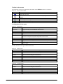
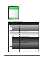
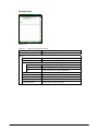
Table of the Contents
Chapter 1.
1.1
1.2
Chapter 2.
2.1
2.1.1
2.1.2
2.1.3
2.1.4
2.1.5
2.1.6
2.1.7
2.1.8
2.1.9
2.1.10
2.2
2.2.1
2.2.2
2.2.3
2.2.4
2.2.5
2.2.6
2.2.7
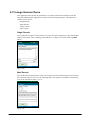
2.3
2.3.1
2.3.2
2.3.3
2.3.4
2.3.5
2.4
2.4.1
2.4.2
2.4.3
2.5
2.5.1
2.5.2
2.5.3
2.6
2.6.1
2.6.2
2.7
2.7.1
2.7.2
2.7.3
Editorial Record
Preview
Product Overview
Model by Feature
Available Options
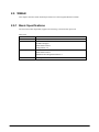
Functions
Basic Specifications
Windows Mobile 6.1
Display
Touch Panel
Keys
Audio
Buzzer Sounds
Memory Management
Reset
Memory Corruption Check
LED
Laser Scanner
Basic Specifications
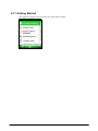
Scanning Method
Scanning Parameters
Scanning Output Format
Scan Result Notification
Expanded Features
Power Control
CMOS Imager
Basic Specifications
Scanning Method
Scanning Parameters
Scan Result Notification
Expanded Features
Digital Camera
Basic Specifications
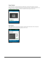
Capturing Images
Image Process
USB
Basic Specifications
COM Port
Product ID
IrDA
Communication Speeds
COM Port
Bluetooth
Basic Specifications
Communication Profiles
Security
2
6
7
8
8
9
10
10
10
11
13
14
21
22
23
25
28
29
32
32
34
36
39
47
48
68
69
69
71
73
75
76
85
86
87
92
93
93
94
94
95
95
95
96
96
97
98
2.7.4
2.7.5
2.7.6
2.7.7
2.7.8
2.7.9
2.7.10
2.7.11
2.8
2.8.1
2.8.2
2.8.3
2.8.4
2.8.5
2.8.6
2.9
2.9.1
2.9.2
2.10
2.10.1
2.10.2
2.11
2.11.1
2.11.2
2.11.3
2.11.4
2.11.5
2.11.6
2.11.7
2.11.8
2.11.9
2.11.10
2.12
2.12.1
2.12.2
2.12.3
Chapter 3.
3.1
3.2
3.3
3.4
3.5
3.6
3.7
3.8
3.9
3.10
3.11
3.12
3.13
COM Port
Communication Procedure
Communication Procedure by Profile
Process after Communication Interruption
Process During Suspend and Resume
Setting SR Mode Parameter
Simultaneous Use with WLAN
Communication Range
WLAN
Basic Features
Expanded Features
Roaming
Zeroconfig
Channels
WLAN Setting with Configuration File
WWAN
Basic Specifications
Available Features
GPS Positioning Function
Basic Specifications
GPS Function API
Power Control
Monitoring Low Voltage
Power ON Factors
Power OFF Factors
Controls on Power Key
Power Saving
CPU Power State Control
Virtual OFF by Application
Virtual OFF by System
Charging/Supplying the Power
Temperature Control
Security
Setting Password for Terminal
Setting Individual ID
Setting Distributor ID
Control Panel Applets
Buttons
Input
Lock
Menus
Owner Information
Sounds & Notifications
Today
About
Backlight
Buzzer
Certificates
Clock & Alarms
CPU Speed
3
98
99
100
101
101
101
102
103
104
104
105
106
107
108
108
115
115
116
118
118
119
127
127
130
131
132
133
135
137
139
140
141
142
142
142
142
143
146
148
150
152
153
155
156
158
160
163
164
166
168
3.14
3.15
3.16
3.17
3.18
3.19
3.20
3.21
3.22
3.23
3.24
3.25
3.26
3.27
3.28
3.29
3.30
3.31
3.31.1
3.31.2
3.31.3
3.31.4
3.31.5
3.31.6
3.32
3.33
3.34
3.35
3.36
3.37
3.38
3.39
3.40
Chapter 4.
4.1
4.2
4.3
4.4
4.5
4.6
4.7
4.8
4.9
4.10
4.11
4.12
4.13
4.14
4.15
4.16
Customer Feedback
Encryption
Error Reporting
External GPS
Imager Setting
Managed Programs
Memory
Power
Regional Settings
Remove Programs
Scanner Setting
Screen
Task Manager
USB Connection
Version Info
Windows Update
Beam
Bluetooth
Devices
Services
My Device
Shortcut
Default Devices
Setup Wizard
Connections
Domain Enroll
Network Cards
USB to PC
WAN Settings
Wireless Manager
Wireless Configuration
WLAN Power
WLAN Settings
Application Programs
Today
Games
ActiveSync
Backup Tool
Calculator
Calendar
Contacts
Copy Devices
File Explorer
FLCE
Getting Started
GPS Information
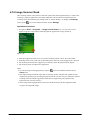
Image Scanner Demo
Image Scanner Read
Internet Explorer
Internet Sharing
4
169
170
171
172
174
182
183
184
185
188
189
193
195
196
198
199
200
201
201
205
220
230
233
235
238
239
240
241
242
259
260
261
262
267
269
270
271
272
278
279
281
282
285
286
287
288
290
292
293
294
4.17
4.18
4.19
4.20
4.21
4.22
4.23
4.24
4.25
4.26
4.27
4.28
4.29
4.30
Chapter 5.
5.1
5.2
5.3
5.4
5.5
Chapter 6.
6.1
6.2
6.3
6.4
Laser Scanner Demo
Laser Scanner Read
Messaging
Messenger
Mobile Camera
NetSearch
Notes
Pictures & Videos
Remote Desktop Mobile
Search
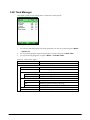
Task Manager
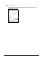
Tasks
Windows Live
Windows Media
Utilities
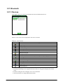
FCHKCE
Auto Setup
TextEditor
CT Client
DSKClean
PC Application Programs
ActiveSync
Windows Mobile Device Center (WMDC)
LMWIN
FCHK
295
297
298
305
306
308
312
314
318
319
320
321
322
323
326
326
327
328
329
330
332
332
332
333
333
No part of this document may be produced or transmitted in any form or by any means, electronic
or mechanical, for any purpose, without the express written permission of CASIO Computer Co.,
Ltd. in Tokyo Japan. Information in this document is subject to change without advance notice.
CASIO Computer Co., Ltd. makes no representations or warranties with respect to the contents or
use of this manual and specifically disclaims any express or implied warranties of merchantability
or fitness for any particular purpose.
© 2009 CASIO Computer Co., Ltd. All rights reserved.
5
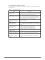
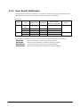
Editorial Record
Manual
Version no.
1.00
Date edited
Page
May 2009
all
Content
Original version
6
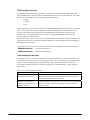
Preview
The features and specifications described in this reference manual give you an overview of the
functional detail of the DT-X30 series handheld terminals with the integrated Windows Mobile®
Version 6.1 OS.
For DT-X30 series handheld terminals with the integrated Windows® CE OS, see DT-X30
Software Manual available separately.
7
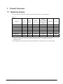
1. Product Overview
1.1 Model by Feature
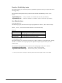
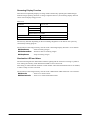
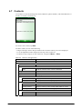
The major features integrated in each model of the DT-X30 series are shown below.
Table 1.1
Model no.
OS
(Note 1)
Scan
Engine
WLAN
(802.11 b/g)
WWAN
(GSM, GPRS,
EGPRS/EDGE),
GPS
No
Yes
Yes
No
Yes
Yes
Yes
Yes
Bluetooth
Camera
DT-X30R-15
Mobile
Laser
Yes
Yes
DT-X30GR-15
Mobile
Laser
Yes
Yes
DT-X30GR-15C
Mobile
Laser
Yes
Yes
DT-X30R-35
Mobile
Imager
Yes
Yes
DT-X30GR-35
Mobile
Imager
Yes
Yes
DT-X30GR-35C
Mobile
Imager
Yes
Yes
DT-X30G-35U
Mobile
Imager
No
Yes
DT-X30G-35UC
Mobile
Imager
No
Yes
Notes:
1. “Mobile” denotes that the model integrates Windows Mobile® 6.1 English Version for its
operating system.
2. The table shows all the models with Windows Mobile® OS available current as of May 2009.
8
No
No
Yes
No
No
Yes
No
Yes
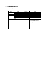
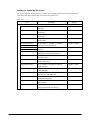
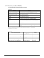
1.2 Available Options
The following dedicated options are available for DT-X30 series.
Table 1.2
Option
Cradle
Battery
Battery charger
Product
USB Cradle
Ethernet Cradle
Battery Pack
Dual Battery Charger
Cradle-type Battery Charger
Car Mounted-type Battery
Charger
Model no.
HA-G60IO
HA-G62IO
HA-G20BAT
HA-G32DCHG
HA-G30CHG
HA-G35CHG
AC Adaptor
AD-S42120B
Power Cable for AD-S42120B
AC-CORD-EU
AC-CORD-US
AC-CORD-TW
AC-CORD-KR
AC-CORD-AU
DT-380USB
HA-G90PS5
Cable
Others
USB cable
Screen Protect Sheet
9
Remark
For HA-G60IO, HA-G62IO,
HA-G30CHG, HA-G32DCHG
For Europe
For USA/Canada
For Taiwan
For Korea
For Australia
For cradle - PC
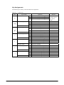
2. Functions
This chapter describes about detailed specifications of the functions implemented in the terminal
and the options.
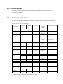
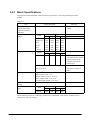
2.1 Basic Specifications
This chapter describes about basic specifications of the terminal.
2.1.1 Windows Mobile 6.1
The terminal integrates Microsoft® Windows Mobile® Version 6.1 as its operating system. The
operating system features with the following capabilities.
•
•
•
•
•
•
•
•
•
Easy-to-use user interface
Improvement of kernel (note)
Large file size (4GB) is supported.
SDHC card (SDHC Ver2.0 standard) is supported.
RDP6.0 is supported.
Easy development thanks to open environment.
PPC application operation with AYGShell
.NET Compact FrameWork 2.0 is supported.
High speed processing
10
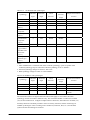
2.1.2 Display
Basic Specifications
The QVGA (320 x 240 dots) mode is supported by the terminal.
Table 2.1
Display specification
Display size X direction
Y direction
65,536 colors 2-way TFT LCD* (16 bpp, Red: 5 bits, Green: 6 bits, Blue: 5 bits)
240 dots
320 dots
* Dead Pixels
The LCD panel employed in this product uses high precision and substantial number of components
which commonly cause a small number of the pixels not to light or to remain lit all the time. This is
due to the characteristics of LCD panel yield in accuracy over 99.99% and permissible.
Backlight Brightness
• A brightness of the backlight can be changed at the Control Panel.
• Setting can be made in one of nine grades for power source either when the power is provided
by an external power supply (with connected AC Adaptor via cradle) or when the power is
provided by the installed lithium-ion battery pack.
• Setting can be made in application by using ExtEscape()API function.
• If the brightness is set to 1 (minimum), the backlight is turned off.
• The default is 9 (maximum) when an external power source is used or 7 when the lithium-ion
battery pack is used.
The functions of the System Library relevant to the Backlight Brightness are as follows.
SysGetBLBattery
: Retrieves brightness of the screen when the power is supplied by battery
pack.
SysSetBLBattery
: Sets up brightness of the screen when the power is supplied by battery
pack.
SysSetBLExpower
: Sets up brightness of the backlight when the power is supplied by
external power.
SysGetBLExpower : Retrieves brightness of the backlight when the power is supplied by
external power.
SysGetBLMaximum : Retrieves the maximum value of brightness for the backlight.
11
Backlight Auto Dimming
The Control Panel can be used to set up whether or not the Auto Dimming function is used and
the waiting time until when dimming begins. Auto dimming is set effect only when the power is
provided by the lithium-ion battery pack. It will not function when an external power supply is
used.
• If the terminal is left over in idle state - absolutely no key input - while the power is turned on,
the backlight will be automatically dimmed to save the power after a given period of time has
been elapsed. When the terminal is in the auto dimmed state, a press of key disables the auto
dimming function to resume the brightness.
• While the Auto Dimming function has been set effect, the brightness can be set in one of eight
grades. The default is 3. During the Auto Dimming function being set effect, the brightness
cannot be set any brighter than the brightness illuminated by the backlight. The defaults are
“Enable the auto dimming function” and “1 minute” for waiting time period until when the
Auto Dimming function activates.
Auto Backlight OFF
The Control Panel can be used to set up whether or not the Auto Backlight OFF function will be
used and the waiting time until when the Auto Backlight OFF function activates. The Auto
Backlight OFF function is operable for both when the power is provided by an external power
source and when it is provided by the lithium-ion battery pack.
• If the terminal is left over in idle state - absolutely no key - with the power being turned on,
the backlight will be automatically turned off to save the power.
• When the terminal is in the Auto Backlight OFF state, pressing a key disables the Auto
Backlight OFF function to resume the brightness.
• While the power is being provided by the lithium-ion battery pack and both the Auto
Dimming function and the Auto Backlight OFF function have been set enabled, either one of
the functions with preset time period shorter than the other will have the priority. The default
is “Enable the Auto Backlight OFF function” and “5 minutes for the waiting time” until when
the Auto Backlight OFF function activates.
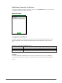
Flipping Display Screen
Flipping display screen at 90, 180 or 270 degree is supported.
• The System Library can be used to set up an angle to flip the screen in application.
• ChangeDisplaySettingEx() API function can be used to set up this display screen flip
feature in application.
See Microsoft Help for detail about ExtEscape() and ChangeDisplaySettingEx() API
functions.
The functions of the System Library relevant to the Flipping Display Screen are as follows.
SysSet180Rotate : Sets up a flip angle for the screen.
SysGet180Rotate : Retrieves the status of flip angle for the screen.
12
2.1.3 Touch Panel
An input can be made into any portion of the screen on the touch panel. The touch panel has the
following resolutions.
Table 2.2
Resolution
X direction
Y direction
240 dots
320 dots
• Capturing touch coordinates in X and Y directions and controlling the pointing are possible by
application. Prior to using the touch panel for the first time, calibrating the touch panel is
required.
Tap Sound
The Control Panel can be used to set up the tap sound to mute, low or loud.
Tap and Hold
By tapping and holding onto a specific object on the screen, the related pop-up menu appears.
Flipping Touch Panel Coordinates
When the screen flips, the coordinates of the touch panel also flip in unison.
Touch Panel Calibration
Calibration on the touch panel can be initiated either using the Welcome wizard appeared after
disk clear or by simultaneously pressing Fn and 4 keys.
The touch panel may require periodical calibration if it slipped off due to aged deterioration,
voltage fluctuation, temperature change, etc. If it happed on your screen, perform the calibration
using one of the methods.
13
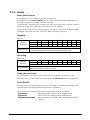
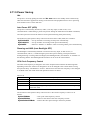
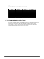
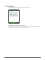
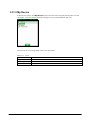
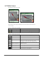
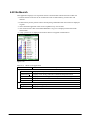
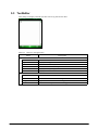
2.1.4 Keys
Keyboard Layout
The following is the keyboard layout employed in the terminal.
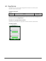
Figure 2.1
14
Key Assignments
The following are the key codes and function assignments.
Table 2.3
KEY
Control keys
Input mode
----
Fn
Character input mode
CLR
Function mode
Character input mode
Function mode
Character input mode
↑
Function mode
Character input mode
↓
Function mode
Character input mode
←
Function mode
Character input mode
→
Function mode
1
A
Operation
Specialized key operation (toggle).
Specialized key operation (toggle).
a
Specialized key operation (toggle).
1
A
a
F
1
A
a
F
1
A
a
F
1
A
a
F
1
A
a
F
1
A
a
F
Deletes one character to the left.
Deletes one character to the left.
Deletes one character to the left.
Performs as ESC key.
Performs as Enter key.
Performs as Enter key.
Performs as Enter key.
Performs as Shift and Enter keys.
Performs as Cursor up key.
Performs as Cursor up key.
Performs as Cursor up key.
Performs as Shift and TAB keys.
Performs as Cursor down key.
Performs as Cursor down key.
Performs as Cursor down key.
Performs as TAB key.
Perform as “Cursor left key”.
Perform as “Cursor left key”.
Perform as “Cursor left key”.
Perform as “Cursor left key”.
Perform as “Cursor right key”.
Perform as “Cursor right key”.
Perform as “Cursor right key”.
Perform as “Cursor right key”.
15
Remarks
Fn mode is
released when a
key input is
made.
Table 2.4
KEY
F1
Function keys
Input mode
Character input mode
F2
Function mode
Character input mode
F3
Function mode
Character input mode
F4
Function mode
Character input mode
F5
Function mode
Character input mode
F6
Function mode
Character input mode
F7
Function mode
Character input mode
F8
Function mode
Character input mode
Function mode
1
A
a
F
1
A
a
F
1
A
a
F
1
A
a
F
1
A
a
F
1
A
a
F
1
A
a
F
1
A
a
F
Operation
Performs as F1 key.
Performs as F1 key.
Performs as F1 key.
Performs as BS key.
Performs as F2 keys.
Performs as F2 keys.
Performs as F2 keys.
Performs as F2 keys.
Performs as F3 key.
Performs as F3 key.
Performs as F3 key.
Performs as F3 key.
Performs as F4 key.
Performs as F4 key.
Performs as F4 key.
Performs as “–” (Hyphen) key.
Performs as F5 key.
Performs as F5 key.
Performs as F5 key.
Performs as Space key.
Performs as F6 key.
Performs as F6 key.
Performs as F6 key.
Performs as F6 key.
Performs as F7 key.
Performs as F7 key.
Performs as F7 key.
Performs as F7 key.
Performs as F8 key.
Performs as F8 key.
Performs as F8 key.
Changes input mode.
Navigate to Numeric → Alphabet
(uppercase) → Alphabet (lowercase)
16
Remarks
Left Soft Key
Left Soft Key
Left Soft Key
Right Soft Key
Right Soft Key
Right Soft Key
Right Soft Key
Volume up
Volume up
Volume up
Volume up
Volume down
Volume down
Volume down
Volume down
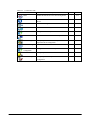
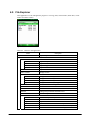
Table 2.5 Trigger keys
KEY
Input mode
R Trigger Character input
mode
L Trigger
Trigger
Center
Function mode
Character input
mode
Function mode
Character input
mode
Function mode
Table 2.6
KEY
0
1
2
3
Ten key
Input mode
Character input
mode
Function mode
Character input
mode
Function mode
Character input
mode
Function mode
Character input
mode
Function mode
Function mode
4
5
6
Function mode
Character input
mode
Function mode
Character input
mode
Function mode
Operation
Remarks
1
A
a
F
1
A
a
F
1
A
a
F
VK_OEM_RTR
VK_OEM_RTR
VK_OEM_RTR
VK_OEM_RTR
VK_OEM_LTR
VK_OEM_LTR
VK_OEM_LTR
VK_OEM_LTR
VK_OEM_CTR
VK_OEM_CTR
VK_OEM_CTR
VK_OEM_CTR
Operation
Performs as 0 key.
Performs as “-_ / ^\&=+$%#* space” keys.
Performs as “-_ / ^\&=+$%#* space” keys.
Displays SIP or does not display.
Performs as 1 key.
Performs as “?!()<>[]{}” keys.
Performs as “?!()<>[]{}” keys.
Turns on or off the backlight.
Performs as 2 key.
Performs as “A”, ”B” and ”C” keys.
Performs as “a”, ”b” and ”c” keys.
Darkens the contrast.
Performs as 3 key.
Performs as “D“, ”E” and ”F” keys.
Performs as “d”, ”e” and ”f” keys.
Brightens the contrast.
Performs as 4 key.
Performs as “G”, ”H” and ”I” keys.
Performs as “g”, ”h” and ”i” keys.
Start the screen of Mouse Properties
Performs as 5 key.
Performs as “J”, ”K” and ”L” keys.
Performs as “j”, ”k” and ”l” keys.
Darkens the backlight.
Performs as 6 key.
Performs as “M”, ”N” and ”O” keys.
Performs as “m”, ”n” and ”o” keys.
Brightens the backlight.
Remarks
1
A
a
F
1
A
a
F
1
A
a
F
1
A
a
F
1
A
a
F
1
A
a
F
1
A
a
F
Continue.
17
7
8
9
.
(Decimal
point)
Character input
mode
Function mode
Character input
mode
Function mode
Character input
mode
Function mode
Character input
mode
Function mode
1
A
a
F
1
A
a
F
1
A
A
F
1
A
a
F
Performs as 7 key.
Performs as “P”, ”Q”, ”R” and ”S” keys.
Performs as “p”, ”q”, ”r” and ”s” keys.
Start the application.
Performs as 8 key.
Performs as “T”, ”U” and ”V” keys.
Performs as “t”, ”u” and ”v” keys.
Start the application.
Performs as 9 key.
Performs as “W”, ”X”, ”Y” and ”Z” keys.
Performs as “w”, ”x”, ”y” and ”z” keys.
Start the application.
Performs as “.” key.
Performs as “@.,”’`:;~|” keys.
Performs as “@.,”’`:;~|” keys.
Performs as “-” key.
Key Input Mode Switchover
The A (Fn+F8) key on the keyboard can be used to change the key input mode.
Indication of Key Input Mode
Key input mode currently specified appears in the title bar. The modes that can be displayed are
“1” as numeral, “A” as alphabets in uppercase letter, and “a” as alphabets in lowercase letter.
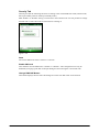
Figure 2.2
Turnover Key Auto Confirmation
After pressing a turnover key, if the preset time period has been elapsed from the time when the
turnover key is released, the turnover character input will be automatically made. The Control
Panel can be used to set up “Enable” or “Disable” for the auto confirmation on the turnover
character input and to set up the time period until when its confirmation is made.
Key Repeat
Continuously pressing of any of the “0” to “9”, “ ↑“, “←”, “→” and “ ↓“ keys repeats the key
input.
Key Click Sound
The key click sound is generated when a key is pressed. However, it is not generated when the key
is released or in mid-course of repeating the key input. The Control Panel can be used to set up the
sound to mute, low or loud.
18
Enabling or Disabling Fn Key
For keys that perform specialized operations while the key input mode has been set to Function
mode, “Enable” or “Disable” can be set on each individual key in the registry below to control the
operations.
[HKEY_LOCAL_MACHINE\HARDWARE\DEVICEMAP\KEYBD]
Or, using the SysSetFnKeyOperation function of the System Library can achieve the same
control operation explained above.
Table 2.7
Key
Setting Value
Meaning
DisableFn9
dword: 0 or 1
Enable or Disable
DisableFn8
dword: 0 or 1
Enable or Disable
DisableFn7
dword: 0 or 1
Enable or Disable
DisableFn6
dword: 0 or 1
Enable or Disable
DisableFn5
dword: 0 or 1
Enable or Disable
DisableFn4
dword: 0 or 1
Enable or Disable
DisableFn3
dword: 0 or 1
Enable or Disable
DisableFn2
dword: 0 or 1
Enable or Disable
DisableFn1
dword: 0 or 1
Enable or Disable
DisableFn0
dword: 0 or 1
Enable or Disable
The functions of the System Library relevant to the “Enabling or Disabling Fn Key” are as
follows.
SysSetFnKeyOperation : Sets up “Enable” or “Disable” for the Fn key operation.
SysGetFnKeyOperation : Retrieves “Enable” or “Disable” status for the Fn key operation.
Function Mode Notification
When the Fn key is pressed, the WM_USER+0x502 message is issued to application. This enables
the application to detect whether the Function mode has been set up enabled or disabled.
Enable or Disable the A Key
The System Library can be used to make the setting on “Enable” or “Disable” for switching over
the key input mode in application.
The functions of the System Library relevant to the “Enable or Disable the A Key” are as follows.
SysSetFnKeyLock : Sets up “Enable” or “Disable” for the Fn key to activate.
SysGetFnKeyLock : Retrieves “Enable” or “Disable” status for the Fn key to activate.
A Key Notification
When the A key is pressed, the WM_USER+0x506 message is issued to application. Using this
notification, the application can detect whether the key input mode has been changed.
19
Permit or Prohibit Key Locks
The System Library can be used to permit or prohibit the operations of keys except for the Power
and Trigger keys.
The functions of the System Library relevant to the “Permit or Prohibit Key Locks” are as
follows.
SysSetAllKeyLock : Sets up “Enable” or “Disable” for lock with specified key.
SysGetAllKeyLock : Retrieves “Enable” or “Disable” status for lock with specified key.
User Settable Keys
Initiating application
The following registry can be used to assign any application to the Fn+7, Fn+8 and Fn+9 keys.
[HKEY_LOCAL_MACHINE\HARDWARE\DEVICEMAP\KEYBD]
Table 2.8
Key
Fn7LaunchPath
Fn8LaunchPath
Fn9LaunchPath
Setting Value
sz: Target application in full path to initiate
sz: Target application in full path to initiate
sz: Target application in full path to initiate
• Setting Key Codes
The System Library can be used to assign any key code to all the keys except the Fn key. Setting
“Enable” or “Disable” for assigning key code is possible using the System Library or at the
Control Panel.
The functions of the System Library relevant to the “Setting Key Codes” are as follows.
SysSetNormalUserDefineKey : Sets up key codes (in normal mode).
SysGetNormalUserDefineKey : Retrieves key codes (in normal mode).
• The key codes after setting are valid only when the numeral input mode is set enabled.
20
2.1.5 Audio
Basic Specifications
WAV playback, voice recording and playback are supported.
By using the Microsoft SoftwareMixer function, output sounds from multiple applications can
be mixed and output (in 44.1 KHz, 16-bit stereo mixing).
Voice Recorder is integrated in the terminal as the sound system application to make it possible to
perform WAV file streaming playback and local file playback in HTTP.
Audio and Buzzer use the same integrated speaker, therefore it is not possible to playback Audio
and Buzzer sound at the same time. In this case, Buzzer sound has the priority.
Playback
Table 2.9
Sampling
frequencies
Stereo/Monaural
KHz
8
11.025
12
16 22.05
24
32
44.1
Mono
Yes
Yes
Yes Yes
Yes
Yes Yes Yes
Stereo
Yes
Yes
Yes Yes
Yes
Yes Yes Yes
Sampling frequencies other than those above are not supported.
8-bit or 16-bit
In reality, the integrated monaural speaker does not output sound in stereo.
48
Yes
Yes
KHz
8
11.025
12
16
22.05 24
Monaural Yes
Yes
Yes Yes
Yes
Yes
Sampling frequencies other than those above are not supported.
8-bit or 16-bit
Monaural sound input only via the microphone.
48
Yes
Recording
Table 2.10
Sampling
frequencies
Stereo/Monaural
32
Yes
44.1
Yes
Setting Sound Volume
The Control Panel can be used to set up sound volume in six grades from loud to low and
ON/OFF of mute. A sound volume also can be set up using Win32 API function in application.
Audio ON/OFF
The audio system can be disabled to save the power. “Enable” or “Disable” for the audio system
in the terminal is controlled using the System Library in application.
The functions of the System Library relevant to the Audio ON/OFF are as follows.
SysAudioOff
: Turns off the audio virtually with the audio turned off.
SysAudioOn
: Turns on the audio virtually with the audio turned on.
SysGetAudioPowerState : Retrieves “Enable” or “Disable” status for turning off the audio
virtually.
21
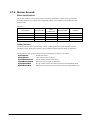
2.1.6 Buzzer Sounds
Basic Specifications
The buzzer sound in various modes such as scanning confirmation, alarm, warning, and other
available sounds can be output via the integrated speaker. The sounds have four attributes and
default values.
Table 2.11
Sound Mode
Alarm
Warning
Scan end
User designated
Frequency (Hz)
3500
3000
3300
--
Time
(millisecond)
150
100
75
--
Individual Mute
Attribute
ON or OFF
ON or OFF
ON or OFF
ON or OFF
B_ALARM
B_WARNING
B_SCANEND
B_USERDEF
Setting Volume
The Control Panel can be used to set up volume in three grades from loud, medium, low and
ON/OFF of mute. Setting the volume is also possible using the System Library in application.
The functions of the System Library relevant to the Setting Volume are as follows.
SysPlayBuzzer
: Sounds the buzzer.
SysStopBuzzer
: Turns off the buzzer’s sound.
SysSetBuzzerVolume : Sets up sound volume of the buzzer.
SysGetBuzzerVolume : Retrieves sound volume of the buzzer.
SysSetBuzzerMute
: Sets up sound volumes for all the parameters and individual mutes.
SysGetBuzzerMute
: Retrieves the statuses of all the sound volumes and individual mutes.
22
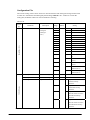
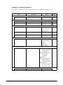
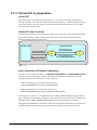
2.1.7 Memory Management
The high speed and large capacity RAM (MobileDDR 128MB) and FlashDisk (NAND Flash
128MB) are integrated in the terminal.
Although RAM has been used for RAM XIP (for OS), program memory (for program files) and
object store (for work area) in the past, it is unified presently to integrate FlashDisk on root folder.
Before
128MB RAM
RAM XIP
Program Memory
Execute OS files deployed on RAM
OS work
Object Store
Execute Program
Work Area
128MB OneNAND
Boot loader
OS Disk
User Disk
Initialization
OS files for deployment on RAM
NAND Disk
From now on
Windows
CE models
128MB RAM
RAM XIP
Program Mmemory
Execute OS files deployed on RAM
OS Work
Execute Program
128MB OneNAND
Boot loader
Initialization
OS Disk
User Disk
OS files for deployment on RAM
NAND Disk
Windows
MobileMobile
models
DT-X30 Windows
series
128MB RAM
RAM XIP
Program Memory
Execute OS Binary deployed on RAM OS Work
Execute Program
128MB FlashROM
Boot loader
ULDR
Initialization Updater
Kernel
IMGFS
User Disk
OS Binary
OS Files
NAND DISK
Figure 2.3
Notes:
• Patch files, program files and data are not lost even if the battery pack runs down. Thanks to
this, it is no longer needed to back up object store in the RAM.
• Although object store (RAM) is initialized by a full reset in the past, the functions to clear OS
and reload it are supplied.
• If user disk is formatted, registry, program files and data are initialized to the factory defaults
respectively prior to shipment.
• Although the folder named FlashDisk keeps the compatibility, it is not possible to format this
folder.
23
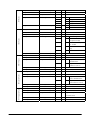
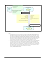
RAM
RAM XIP
Program Memory
Execute OS files deployed on RAM
OS Work
Execute Program
CAMERA
Buffer
DrvGlob
Buffer
The integrated RAM has a total capacity of 128 MB and is used for the below purposes.
Driver glob and buffer : Work area for driver and so on.
OS area
: Area to carry out deployed OS.
Program memory
: Memory area to carry out program and for the OS work area.
Figure 2.4
• The DriverGlob is allocated for the work area of drivers. The camera buffer used in the
terminal for the integrated digital camera deploys camera data temporarily on taking images.
The OS files are deployed from FlashDisk to RAM, and work in the RAM quickly.
• It takes time to deploy the OS files from the FlashDisk to the RAM on clearing OS, reloading
and booting after the battery pack run down.
• There is not object store corresponded to RAM disk. Due to that, if the files are copied into
root/Windows folder under “My device” folder, data files are stored without back-up operation
even if the battery pack runs down because files are created on user disk of FlashDisk actually.
• A full reset (all memory clear) to delete object store like before is not provided. Instead, the
functions (see Chapter 2.1.8) to clear the OS and reload are made available. Because of this
reason, it is not possible to change the ratio of program memory and object store in the control
applet.
FlashDisk
The FlashDisk has 128MB as its total capacity and is used for the following purposes.
Boot area
: Boot Loader which loads the OS to RAM is stored here.
OS disk
: OS files are stored. Boot loader deploys OS files in the RAM during booting.
User disk
: User can use freely as disk.
Boot loader
ULDR
Initialization Updater
Kernel
IMGFS
User Disk
OS Binary
OS Files
NAND DISK
Figure 2.5
• In the boot area, boot loader and etc. are stored to deploy OS files in the RAM.
• In the OS disk, internal application and etc. are stored.
• The FlashDisk different from RAM does not require a power to back up data in the disk, so
data is not lost even if the terminal’s memory backup battery is exhausted.
• It is not necessary to back up object store like before because the FlashDisk is mounted on
root folder below “My Device”.
• Pay attention when user disk is formatted (see note), because registry, patch files, program
files and data are deleted and then initialized to the factory defaults respectively.
Note:
Formatting is carried out by an exclusive tool on the control applet and special key operation. See
the next chapter concerning the special key operation.
24
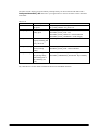
2.1.8 Reset
The role of the boot loader in Windows Mobile (OAL) (see Figure 2.6) is to boot the OS after
initializing the hardware. On the terminal, it is possible to carry out the inspection tool and OS
update tool with special key operation as described in the respective figures below.
BootSelector
(Soft reset (Default))
(Fn+5+Reset)
(Fn+CLR+PWR+Reset)
(Fn+CLR+RESET)
(Fn+CLR+”.”+Reset)
(Fn+Center Trigger+ENT+Reset)
IPL
OS Loader
SD Loader
ULDR
OS Clear and Reload
User Disk Clear
Hard Reset
Figure 2.6 Windows Mobile
To reset the terminal, there are several ways to carry out. The explanation below describes the
methods to reset the terminal.
Soft Reset
The operation requires pressing the reset switch on the back of the terminal. It initializes the
program memory.
OS Clear and Reload
This operation is carried out if Fn and CLR keys are held down at the same time and then the reset
switch is pressed down. It initializes the RAM and reloads the OS again from the OS disk.
Hard Reset
This operation is carried out if Fn, Center Trigger and ENT keys are held down at the same time
and then the reset switch is pressed down. The RAM and Clock (RTC) are initialized and then the
system restarts.
25
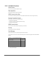
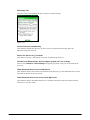
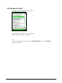
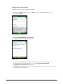
User Disk Clear
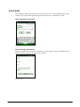
This operation is carried out if Fn and CLR and “.” keys are held down at the same time and then
the reset switch is pressed for a period of one second or longer while the terminal is in operation.
A message (see Figure 2.7) to confirm memory initialization appears. The R Trigger key is used to
confirm the User Disk Clear.
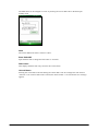
Figure 2.7
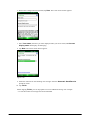
After the R Trigger key is pressed twice, User disk is formatted and RAM are initialized to the
factory condition (see note).
Figure 2.8
Notes:
• Distributor ID is not cleared.
• The utility to carry out the User Disk Clear is available. See “DSKClean” for detail.
26
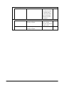
Power-on Reset
After the battery pack and memory backup battery are demounted and then put back into the
terminal, this state occurs when the Power switch is turned on for the first time. When the Power
switch is turned on in this state, the Boot Loader performs the reset (RTC is initialized if it is
necessary).
Table 2.12
RAM
OS
Program
Memory
Memory
No
Initialized
Reloaded Initialized
Reloaded Initialized
Reloaded Initialized
Reloaded Initialized
Reloaded Initialized
Reloaded Initialized
EEPROM
FlashDisk
Clock (RTC)
Individual ID
Distributor ID
Soft Reset
No
No
No
No
OS Clear, Reload
No
No
No
No
Hard Reset
No
Initialized
No
No
User Disk Clear
Initialized
No
No
No
Power-on Reset
No
No/Initialized
No
No
SD Loader
No
No
No
No
ULDR
No
No
No
No
Note:
“No” in the table indicates that the content in the memory is not initialized by the reset method.
27
2.1.9 Memory Corruption Check
To confirm checksum is carried out in order to detect whether the OS deployed in the memory is
corrupted or not, and the OS is reloaded if it is necessary.
Table 2.13
On Soft Reset
Confirm the checksum
Carried out
On OS Clear, Reload, Hard Reset, User
Disk and Power-on Reset
On Suspend and Resume
-
OS load
Carried out when error of
check-sum occurs.
Carried out
None
None
Notes:
• The reason to confirm whether the checksum is not carried out on suspending and resuming
is for high-speed performance. But memory corruption check is done in order to confirm
whether RAM is in the error status by any reasons or not.
• This writes down fixed data (0x00 to 0xFF) previously into fixed area (256 bytes area) on
the RAM, and compares the value on resuming. When error is detected, warning message
for memory corruption check is issued, and then reset is performed.
28
2.1.10 LED
Basic Specifications
There are two LEDs integrated in the terminal, one on the right side for the user notifications and
the other for charging the battery complete notification.
Table 2.14
LED
Right side LED
Left side LED
Color
Red
Green
Blue
Orange
Cyan
Magenta
Orange
Green
Red
Description
User notification (alarm), scanning a bar code
Scanning a bar code
Connection established via Bluetooth
Connection established via WLAN, WWAN or GPS
User defined
User defined
While charging battery pack.
Charging battery pack is complete.
Charging Error.
Notes:
• The user notification LED (Indicator #2) on the right side can be used to indicate various
notifications by the OS and other notifications defined by the user.
• All colors available in the LED (Indicator #2) on the right side are indicated with the
System Library.
• The charging battery complete LED (Indicator #1) on the left side cannot be controlled or
manipulated for its ON/OFF state and color with software.
User Notification (Alarm)
This indication mode is used for alarm notification and etc. The LED can be lit for a specific time
with CeSetUserNotification()API function.
Table 2.15
Operating mode
Specification
Blink interval
ON in red for 1 second, OFF for 2 seconds
Continuous ON time
ON for 30 minutes (OFF when VDET is detected.)
Note:
Indication for scanning a bar code has the priority over other indications.
Scanning
This is used for notification of a scanning result which is controlled with the System Library.
Table 2.16
Operating mode
Scanning complete
Scanning in error
Specification
ON in green for a specified period of time, then OFF.
ON in red for a specified period of time, then OFF.
29
Attribute
L_SCANOK
L_SCANERR
Bluetooth Connection Status
This is used for notification of Bluetooth connection establishment status which is controlled with
the System Library.
Table 2.17
Operation mode
Specification
Bluetooth established
ON in blue for 1 second, OFF for 2 seconds
Note:
Indication for scanning a bar code has the priority over other indications.
Attribute
L_BT
WLAN Connection Status
This is used for notification of WLAN connection establishment status which is controlled with
the System Library.
Table 2.18
Operation mode
Specification
WLAN established
ON in orange for 1 second, OFF for 2 seconds
Note:
Indication for scanning a bar code has the priority over other indications.
Attribute
L_WLAN
User Definition
This indication mode is used for other notifications freely defined by the user. The ON/OFF state
and color to be lit can be controlled with the System Library.
Table 2.19
Operation mode
User definition
Specification
Color selection from red, green, blue, orange, cyan and magenta.
Programmable for ON and OFF time periods
30 minutes (OFF when VDET is detected)
Continuous ON time period
Note:
Indication for scanning a bar code has the priority over other indications.
The functions of the System Library relevant to the User Definition are as follows.
SysSetLED : Sets up “Enable” or “Disable” for turning on the LED.
SysGetLED : Retrieves “Enable” or “Disable” status for turning on the LED.
30
WWAN Connection Status
This is used for notification of WWAN connection establishment status.
Table 2.20
Operation mode
Specification
Attribute
WWAN established
ON in orange for 1 second, OFF for 2 seconds
L_WWAN
Notes:
• Indication for scanning a bar code has the priority over other indications.
• User access is supported by the System Library (CLBSetIndicator function).
• The color of indications for WLAN, WWAN and GPS is the same.
GPS Connection Status
This is used for notification of GPS connection establishment status.
Table 2.21
Operation mode
Specification
Attribute
GPS established
ON in orange for 1 second, OFF for 2 seconds
L_GPS
Notes:
• Indication for scanning a bar code has the priority over other indications.
• User access is supported by the System Library (CLBSetIndicator function).
• The color of indications for WLAN, WWAN and GPS is the same.
31
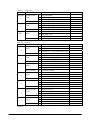
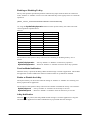
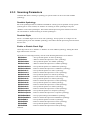
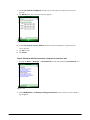
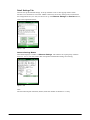
2.2 Laser Scanner
This chapter describes about detailed specifications of the integrated Laser Scanner (model
dependant).
2.2.1 Basic Specifications
The following industrial standard bar code symbologies are supported by the integrated Laser
Scanner.
Table 2.22
Supported symbologies
Symbology
Check Digit Calculation
No. of min.
digits
8 (fixed)
10 (fixed)
7 (fixed)
9 (fixed)
2 (Note 3)
2 (Note 4)
4 (Note 5)
2
1
1
1
1 (Note 6)
14 (fixed)
14 (fixed)
1
14 (fixed)
1
No. of max. digits
EAN, UPC-A, UPC-B
Enable or Disable
13 (fixed)
EAN, UPC-A, UPC-B Addon
Enable or Disable
18 (fixed)
UPC-E
Enable or Disable
7 (fixed)
UPC-E Addon
Enable or Disable
12 (fixed)
Code39
Enable or Disable
52
NW7
Enable or Disable
63
Interleaved 2of5
Enable or Disable
94
Industrial 2of5
Enable or Disable
67
Code93
Enable or Disable
70
Code128
Enable or Disable
98
MSI
Enable or Disable (Note 1)
57
IATA
Enable or Disable (Note 2)
65 (Note 6)
RSS-14 (Note 8)
Enable
14 (fixed)
RSS Limited (Note 8)
Enable
14 (fixed)
RSS Expanded (Note 8)
Enable
74 (Note 7)
RSS-14 Stacked (Note 8)
Enable
14 (fixed)
RSS Expanded Stacked (Note 8)
Enable
74 (Note 7)
Notes:
3. MSI check digit
One of the following MSI check digit calculation methods can be selected.
- 1 digit, mod10
- 2 digit, mod10/mode11
- 2 digit, mod10/mod10
4. IATA check digit
One of the following IATA check digit calculation methods can be selected.
- Calculate number other than end 1 digit
- Calculate coupon number and numeric value segment
- Calculate numeric value segment
- mod10
5. Minimum digit on Code39 symbology
The no. of minimum digits can be set to one digit only when scanning Code39 symbology is
enabled.
32
6. Minimum digit on NW7 symbology
The no. of minimum digits can be set to one digit only when scanning NW7 symbology is
enabled.
7. Minimum digit on Interleaved 2of5 symbology
The no. of minimum digits can be set to two digits only when scanning Interleaved 2of5
symbology is enabled.
8. Minimum and maximum digits on IATA symbology
The no. of minimum digits can be set to 15 digits or 17 digits for the maximum only when the
IATA check digit calculation is set to “Coupon number and Calculate data segment” or
“Calculate just data segment”.
9. The maximum digit count for just numeric data is 74 digits, or the maximum digit count for
just alphabet data is 41 digits.
10. The RSS symbologies change its name to GS1 DataBar.
RSS-14 → GS1 DataBar Omnidirectional
RSS Limited → GS1 DataBar Limited
RSS Expanded → GS1 DataBar Expanded
RSS-14 Stacked → GS1 DataBar Stacked
RSS Expanded Stacked → GS1 DataBar Expanded Stacked
Check Digit Calculation
A bar code value is calculated in accordance with method, and then the calculation result and the
check character at a specific position are compared. If they match each other, the scanning data is
deemed correct. The calculation method differs according to each symbology.
Readable Digits
The actual readable digit on a bar code differs depending on the resolution and the scanning
distance between the terminal and the bar code.
33
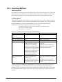
2.2.2 Scanning Method
The Laser Scanner has “scanning state” (emits laser beam to read a bar code) and “standby state”
(scanning is halted and in standby state). These two states are controlled to start scanning bar code
and stop the scanning.
Table 2.23
Scanning methods
Scan method
Single scan
Continuous scan
(controlled with
Trigger key)
Continuous
scanning
(controlled by
program)
Description
Conditions for scanning to end
Press Trigger key to start
scanning. Scanning is
stopped when either
scanning is succeeded or one
of the scan end conditions
(right side) is met.
Press Trigger key to start
scanning, and scanning will
continue as long as the
Trigger key is held down.
Scanning will stop when
either scanning is completed
for just preset no. of times
for scanning or one of the
scan end conditions (right
side) is met.
Scanner library functions are
used to start and stop
scanning. The previous
scanning data and scanning
data overlapped with other
scanning data will be
disregarded. Also, to save the
power during scanning,
emitting laser beam will be
turned off between laser
emissions. (note 2)
• Timeout time has elapsed.
• OBRClose function is called.
Timeout
Yes or
No
Yes
• Timeout time has elapsed after
scanning a bar code.
• Scanning for the number of preset
times is complete.
• The Trigger key is released.
• OBRClose function is called.
Yes
• Timeout time has elapsed after
scanning the precious scanning.
• Scanning end function is called while
scanning continues.
• OBRClose function is called.
Yes
Notes:
1.
The scanning method set by default is with “Continuous scanning (controlled with Trigger
key)” and “No. of preset times for continuous scanning = 1”.
2.
In condition where the parameter in the registry has been set, performing a full reset on the
terminal makes emitting the laser beam is turned off intermittently between laser emissions
possible.
The path of the registry is as follows.
Path
: HKEY_LOCAL_MACHINE\Drivers\CASIO\Laser
Data-type
: DWORD
Parameter : ScnBlk (1: valid, 0: invalid)
34
The functions of the Laser Scanner Library relevant to the Scanning Method are as follows.
OBRStartScanning
: Emits laser beam and start scanning a bar code.
OBRStopScanning
: Stops emitting laser beam and scanning a bar code.
OBRSetScanningType
: Sets up scanning mode.
OBRGetScanningType
: Retrieves the scanning mode.
OBRClose
: Sets up scanning disable status.
OBRSetScanningCounter : Sets up the no. of times for continuous scanning.
OBRGetScanningCounter : Retrieves the no. of times for continuous scanning.
OBRSetScanningTimeout : Sets up a time period of timeout for scanning complete.
OBRGetScanningTimeout : Retrieves timeout of scanning complete.
Multi-step Scanning
This method is for scanning a designated number of bar codes. Once scanning for the designated
number of bar codes has been completed, the scanner closes and not scan again until reopened.
Also, the same bar codes that have been scanned previously cannot be scanned again.
The functions of the Laser Scanner Library relevant to the Multi-step Scanning are as follows.
OBROpen
: Sets up scanning enable status.
OBRClose
: Sets up scanning disable status.
OBRSetScanningCounter : Sets up the no. of times for continuous scanning.
OBRGetScanningCounter : Retrieves the no. of times for continuous scanning.
OBRSetMultiStepReading : Sets up the no. of bar codes to scan in multi-step scanning mode.
OBRGetMultiStepReading : Retrieves the no. of bar codes to scan in multi-step scanning mode.
35
2.2.3 Scanning Parameters
Conditions that allow scanning a symbology in a specific mode can be set for each readable
symbology.
Readable Symbology
Bar code symbologies that are enabled or disabled for scanning can be specified. If only specific
symbologies are to be scanned, set “Enable” for scanning on these symbologies only and
“Disable” on the other symbologies. This educes decode processing time and lowers the error rate.
The default is “Enable scanning on all the symbologies”.
Readable Digits
The no. of readable digits can be set for each symbology. If only specific no. of digits is to be
scanned, specify it for each readable symbology. This reduces decode processing time and lowers
the error rate.
Enable or Disable Check Digit
Check digit can be set to “Enable” or “Disable” for each readable symbology. Setting the check
digit lowers the error rate.
Table 2.24
Symbology
Check Digit Calculation
EAN, UPC-A, UPC-B
Enable or Disable
EAN, UPC-A, UPC-B Addon
Enable or Disable
UPC-E
Enable or Disable
UPC-E Addon
Enable or Disable
Code39
Enable or Disable
NW7
Enable or Disable
Interleaved 2of5
Enable or Disable
Industrial 2of5
Enable or Disable
Code93
Enable or Disable
Code128
Enable or Disable
MSI
Enable or Disable
IATA
Enable or Disable
RSS-14 (note)
Enable
RSS Limited (note)
Enable
RSS Expanded (note)
Enable
RSS-14 Stacked (note)
Enable
RSS Expanded Stacked (note)
Enable
Note:
The RSS symbologies change its name to “GS1 DataBar”.
RSS-14 → GS1 DataBar Omnidirectional
RSS Limited → GS1 DataBar Limited
RSS Expanded → GS1 DataBar Expanded
RSS-14 Stacked → GS1 DataBar Stacked
RSS Expanded Stacked → GS1 DataBar Expanded Stacked
36
Default
Enable
Enable
Enable
Enable
Disable
Disable
Enable
Enable
Enable
Enable
Enable
Disable
Enable
Enable
Enable
Enable
Enable
The functions of the Laser Scanner Library relevant to the Scanning Parameters are as follows.
OBRSetScanningCode
: Sets up scanning with individual bar code symbology.
OBRGetScanningCode
: Retrieves scanning status with individual bar code
symbology.
OBRSetCode39Option
: Sets up scanning with Code39 symbology.
OBRGetCode39Option
: Retrieves decode options of Code39 symbology.
OBRSetNW7Option
: Sets up scanning with NW-7 symbology.
OBRSetNW7OptionEx
: Sets up scanning with NW-7 symbology.
OBRGetNW7Option
: Retrieves decode options of NW-7 symbology.
OBRSetWPCAddonOption
: Sets up scanning with WPC Addon symbology.
OBRSetWPCAddonOptionEx
: Sets up scanning with WPC Addon symbology.
OBRGetWPCAddonOption
: Retrieves decode options of WPC Addon symbology.
OBRSetWPCOption
: Sets up scanning with WPC symbology.
OBRSetWPCOptionEx
: Sets up scanning with WPC symbology.
OBRGetWPCOption
: Retrieves decode options of WPC symbology.
OBRSetUPCEAddonOption
: Sets up scanning with UPC-E Addon symbology.
OBRSetUPCEAddonOptionEx
: Sets up scanning with UPC-E Addon symbology.
OBRGetUPCEAddonOption
: Retrieves decode options of UPC-E Addon symbology.
OBRSetUPCEOption
: Sets up scanning with UPC-E symbology.
OBRSetUPCEOptionEx
: Sets up scanning with UPC-E symbology.
OBRGetUPCEOption
: Retrieves decode options of UPC-E symbology.
OBRSetIDFOption
: Sets up scanning with Industrial 2of5 symbology.
OBRGetIDFOption
: Retrieves decode options of Industrial 2of5 symbology.
OBRSetITFOption
: Sets up scanning with ITF (Interleaved 2of5)
symbology.
OBRGetITFOption
: Retrieves decode options of ITF (Interleaved 2of5)
symbology.
OBRSetCode93Option
: Sets up scanning with Code93 symbology.
OBRGetCode93Option
: Retrieves decode options of Code93 symbology.
OBRSetCode128Option
: Sets up scanning with Code128 symbology.
OBRGetCode128Option
: Retrieves decode options of Code128 symbology.
OBRSetMSIOption
: Sets up scanning with MSI symbology.
OBRGetMSIOption
: Retrieves decode options of MSI symbology.
OBRSetIATAOption
: Sets up scanning with IATA symbology.
OBRGetIATAOption
: Retrieves decode options of IATA symbology.
OBRSetRSS14Option
: Sets up scanning with RSS-14 symbology.
OBRGetRSS14Option
: Retrieves decode options of RSS-14 Stacked
symbology.
OBRSetRSSLimitedOption
: Sets up scanning with RSS Limited symbology.
OBRGetRSSLimitedOption
: Retrieves decode options of RSS Limited symbology.
OBRSetRSSExpandedOption
: Sets up scanning with RSS Expanded symbology.
37
: Retrieves decode options of RSS Expanded
symbology.
OBRSetRSS14StackedOption
: Sets up scanning with RSS-14 Stacked symbology.
OBRGetRSS14StackedOption
: Retrieves decode options of RSS-14 Stacked
symbology.
OBRSetRSSExpandedStackedOption : Sets up scanning with RSS Expanded Stacked
symbology.
OBRGetRSSExpandedStackedOption : Retrieves decode options of RSS Expanded Stacked
symbology.
OBRGetRSSExpandedOption
Validation
Validation is carried out for a specified number of times in the range of 1 to 9 (Default = 3) to
check if scanned data is valid, and then the data is output. The number of validations can be set
either at the Control Panel or using the Laser Scanner Library.
The functions of the Laser Scanner Library relevant to the Validation are as follows.
OBRSetCheckCounter : Sets up the no. of validations for decoding data.
OBRGetCheckCounter : Retrieves the no. of validations for decoding data.
No. of Scanning Times
In “Continuous Scanning” mode, scanning continues for the preset number of scanning times in
the range of 1 to 9 (Default = 1) and then it will stop in waiting mode. The number of times for
scanning can be set either at the Control Panel or using the Laser Scanner Library.
The functions of the Laser Scanner Library relevant to the “No. of Scanning Times” are as
follows.
OBRSetScanningCounter : Sets up the no. of times for continuous scanning.
OBRGetScanningCounter : Retrieves the no. of times for continuous scanning.
Scanning Period
Valid time period of scanning in the range of 1 to 9 (Default = 3) seconds after Trigger key was
pressed down can be set either at the Control Panel or using the Laser Scanner Library. After the
preset time has elapsed, the scanner goes into standby mode waiting for the Trigger key to be
pressed down again.
The functions of the Laser Scanner Library relevant to the Scanning Period are as follows.
OBRSetScanningTimeout : Sets up a time period of timeout for scanning complete.
OBRGetScanningTimeout : Retrieves the timeout of scanning complete.
Double Scanning Prevention
This prevents scanning the same bar code twice while the “Continuous Scanning” mode has been
set. Scanning the same bar code again is prohibited while the scanning continues for the preset
number of times. However, the bar code can be scanned again when the “Continuous Scanning”
newly starts.
38
2.2.4 Scanning Output Format
Formats for outputting results of scanned bar codes can be set.
Table 2.25 Output Formats
No. of
Symbology Standard
digits
WPC
JAN-13
13
EAN-13
13
JAN-8
8
EAN-8
8
JAN-13
15
addon+2
EAN-13
15
addon+2
JAN-13
18
addon+5
EAN-13
18
addon+5
JAN-8
10
addon+2
EAN-8
10
addon+2
JAN-8
13
addon+5
EAN-8
13
addon+5
UPC-A
12
UPC-B
12
UPC-A
14
addon+2
UPC-B
14
addon+2
UPC-A
17
addon+5
UPC-B
17
addon+5
UPC-A
12
UPC-A
14
addon+2
UPC-A
17
addon+5
JAN-13
14
EAN-13
14
JAN-8
14
EAN-8
14
Continue.
Output Format
FFMMMMMNNNNNCT
FFMMMMMNNNNNCT
FFMMMNCT
FFMMMNCT
FFMMMMMNNNNNCAAT
FFMMMMMNNNNNCAAT
Remark
T : Termination code
See Table 2.26 for meaning of
the notations.
Excluding UPC-B, the mod10
check digit calculation is
always performed
FFMMMMMNNNNNCAAAAAT
FFMMMMMNNNNNCAAAAAT
FFMMMMNCAAT
FFMMMMNCAAT
FFMMMMNCAAAAAT
FFMMMMNCAAAAAT
0SMMMMMNNNNNCT
0SMMMMMNNNNNNT
0SMMMMMNNNNNCAAT
0SMMMMMNNNNNNAAT
0SMMMMMNNNNNCAAAAAT
0SMMMMMNNNNNNAAAAAT
SMMMMMNNNNNCT
SMMMMMNNNNNCAAT
SMMMMMNNNNNCAAAAAT
0FFMMMMMNNNNNCT
0FFMMMMMNNNNNCT
0000000FFMMMNCT
0000000FFMMMNCT
39
GTIN
GTIN
GTIN
GTIN
UPC-E
(note 1)
UPC-A
UPC-E
Interleaved 2of5
14
(7)/8
(7)/8
(7)/8
(7)/8
(6)/7
(6)/7
(6)/7
(6)/7
14
14
14
14
(9)/10
(9)/10
(9)/10
(9)/10
(8)/9
(8)/9
(8)/9
(8)/9
(12)/13
(12)/13
(12)/13
(12)/13
(11)/12
(11)/12
(11)/12
(11)/12
3 to Max
3 to Max
1 to Max
1 to Max
3 to Max
1 to Max
2 to Max
00SMMMMMNNNNNCT
0MMNNNMCT
0MMMNN3CT
0MMMMN4CT
0MMMMMNCT
MMNNNMCT
MMMNN3CT
MMMMN4CT
MMMMMNCT
0000000MMNNNMCT
0000000MMMNN3CT
0000000MMMMN4CT
0000000MMMMMNCT
0MMNNNMCAAT
0MMMNN3CAAT
0MMMMN4CAAT
0MMMMMNCAAT
MMNNNMCAAT
MMMNN3CAAT
MMMMN4CAAT
MMMMMNCAAT
0MMNNNMCAAAAAT
0MMMNN3CAAAAAT
0MMMMN4CAAAAAT
0MMMMMNCAAAAAT
MMNNNMCAAAAAT
MMMNN3CAAAAAT
MMMMN4CAAAAAT
MMMMMNCAAAAAT
SBBB -------- BBCST
SAAA ------- AACST
BBB ------- BBCT
AAA ------ AACT
SDDD ------- DDDCST
DDD ------- DDDCT
DDD ------- DDDCT
Industrial 2of5
2 to Max
DDD ------ DDDCT
UPC-E
UPC-E
addon+2
UPC-E
addon+5
Code39
NW7
Continue.
40
GTIN
Last M: 0 to 2
Last N: 5 to 9
Last M: 0 to 2
Last N: 5 to 9
GTIN Last M: 0 to 2
GTIN
GTIN
GTIN Last N: 5 to 9
Last M: 0 to 2
Last N: 5 to 9
Last M: 0 to 2
Last N: 5 to 9
Last M: 0 to 2
Last N: 5 to 9
Last M: 0 to 2
Last N: 5 to 9
See Table 2.27 for meaning of the
notations
See Table 2.28 for meaning of the
notations
See Table 2.29 for meaning of the
notations
Only even number digits used for
scanning readable digits.
See Table 2.30 for meaning of the
notations
Only even number digits used for
scanning readable digits.
Code93
1 to Max
AAA ------ AAAT
MSI
1 to Max
1 to Max
1 to Max
1 to Max
1 to Max
1to Max
1 to Max
AAA ------ AAAT
SBBB ----- BBCST
AAA ------- AAAT
SBBB ------ BBCST
FAAA ------ AAAT
GAAA ------ AAAT
DDD ------ DDCCT
IATA
1 to Max
16
14
16
14
1 to74
1 to 41
16
14
1 to74
DDDDDDDDDD --------- CT
PADDDDDDDDDDDDDDCT
01DDDDDDDDDDDDDCT
DDDDDDDDDDDDDCT
01DDDDDDDDDDDDDCT
DDDDDDDDDDDDDCT
DD ---- DDDT
AA ---- AAAT
01DDDDDDDDDDDDDCT
DDDDDDDDDDDDDCT
DD ---- DDDT
1 to 41
AA ---- AAAT
Code128
Code128
EAN128
(note 3)
RSS-14 (note 2)
RSS Limited (note 2)
RSS Expanded (note 2)
RSS-14 Stacked (note
2)
RSS Expanded
Stacked (note 2)
See Table 2.31 for meaning
of the notations
See Table 2.32 for meaning
of the notations
See Table 2.33 for meaning
of the notations.
See Table 2.34 for meaning
of the notations.
See Table 2.35 for meaning
of the notations
See Table 2.36 for meaning
of the notations.
See Table 2.37 for meaning
of the notations.
See Table 2.38 for meaning
of the notations.
See Table 2.36 for meaning
of the notations.
See Table 2.38 for meaning
of the notations.
Notes:
1.
“C” will not be appended to the output if the no. of scanning digits described in parentheses
in the table above is applicable.
2.
The RSS symbologies change its name to “GS1 DataBar”.
RSS-14 → GS1 DataBar Omnidirectional
RSS Limited → GS1 DataBar Limited
RSS Expanded → GS1 DataBar Expanded
RSS-14 Stacked → GS1 DataBar Stacked
RSS Expanded Stacked → GS1 DataBar Expanded Stacked
3.
EAN-128 changes its name to “GS1-128”.
Table 2.26 WPC symbology
F
Country flag
M
Manufacturer code
N
Product code
S
Number system character
A
Addon data
T
Termination code
C
Mod10 check digit
41
Table 2.27 Code39 symbology
A
ASCII conversion post data
B
ASCII conversion pre-data
C
Mod43 check digit. Becomes data if there is no check digit attached.
S
Start and stop characters
Table 2.28 NW7 symbology
S
Start and stop characters (any one of a, b, c and d)
D
Data
C
Mod16 check digit. Becomes data if there is no check digit attached.
Table 2.29 Interleaved 2of5 symbology
D
Data
C
Mod10 check digit. Becomes data if there is no check digit attached.
Table 2.30 Industrial 2of5 symbology
D
Data
C
Mod10 check digit. Becomes data if there is no check digit attached.
Table 2.31 Code93 symbology
A
ASCII conversion post data
B
ASCII conversion pre-data
C
Mod47 check digit. Becomes data if there is no check digit attached.
S
Start and stop characters
Table 2.32 Code128 symbology
A
ASCII conversion post data
B
ASCII conversion pre-data
Table 2.33 EAN128 symbology
C
Mod47 check digit
S
Start and stop characters
F
Code ID (only “]C1”, EAN128)
G
GS (only 1Dh, EAN128)
Table 2.34 MSI symbology
D
Data
C
Mo10 and Mod11 check digits. Becomes data when there is no check digit attached.
Table 2.35 IATA symbology
D
Data
C
Check digit (IATA). Becomes data when there is no check digit attached.
P
Coupon No
A
Airline No
42
Table 2.36 RSS-14 symbology
D
Numeric data
C
Mod10 check digit
Table 2.37 RSS Limited symbology
D
Numeric data
C
Mod10 check digit
Table 2.38 RSS Expanded symbology
D
Numeric data
A
Alphabet data
The functions of the Laser Scanner Library relevant to the “Scanning Output Formats” are those
listed on page 39. See page 39.
Termination Codes
Choose one of the following five termination codes to attach to the end of decoded data.
CR
LF
CR+LF
TAB
No termination code (default)
The functions of the Laser Scanner Library relevant to the Termination Codes are as follows.
OBRSetSuffixChar : Sets up suffix control code appended to decoding data.
OBRGetSuffixChar : Retrieves suffix control code appended to decoding data.
43
Output Buffer
The scanner scans a bar code and outputs the scanned data using one of the following methods
described in the table.
Table 2.39
Output Method
OBR buffer output
(see note)
-
Key message output
-
Clipboard output
-
Keyboard output
-
Description
Scanned data is output to memory in the Laser Scanner driver.
Scanned data already output to the memory can be captured using the
Laser Scanner Library.
Scanned data can be output with the window message to the specified
window handle.
The window handle is specified using the Laser Scanner Library.
Scanned result is copied to the clipboard and then output to the edit
control focused by caret.
Scanned result is output as a keyboard event to the edit control focused
by caret.
Note:
When a bar code is scanned, its decoded data including the symbology and data size are stored in
the memory of the Laser Scanner driver. This output method has the following features.
• Capture the bar code symbology and data size.
• Capture the data at any timing the user prefers.
• The length of one piece of data is up to 98 characters (maximum) and up to 9 labels can be
stored in the memory. If any new data scanned after exceeding over 9 labels stored already in
the memory will be disregarded.
The functions of the Laser Scanner Library relevant to the Output Buffer are as follows.
OBROpen
: Sets up scanning enable status.
OBRSetBuffType : Sets up decoding data output mode.
OBRGetBuffType : Retrieves decoding data output mode.
OBRGetc
: Retrieves one character from OBR buffer.
OBRGets
: Retrieves character string for one bar code from decoding data storage buffer.
OBRGetStatus
: Retrieves OBR buffer status.
OBRClearBuff
: Clears OBR buffer.
44
Conditions for Terminating Scanning
Scanning is terminated when any one of the following conditions is met.
• Scanning is succeeded.
• Preset timeout period has elapsed.
• OBR buffer becomes a full.
• An abnormal condition is detected in the scan module.
Scan Completion Notification
When scanning is complete, a notification is issued to the application using one of the methods
described in the table. Each notification method can be set to either “Enable” or “Disable”. The
default is “Notification with window message”.
Table 2.40
Method
Window message
Event
None
Description
A window message is issued to the specified window handle. Also, the conditions for
scanning completion can be retrieved by referring to wParam parameter of the window
message.
A predefined event in the registry is issued. The conditions of scanning completion can
be retrieved using the Laser Scanner Library.
No message or event is issued when scanning is complete.
The functions of the Laser Scanner Library relevant to the “Scan Completion Notification” are as
follows.
OBRSetScanningNotification : Sets up scanning complete notification.
OBRGetScanningNotification : Retrieves scanning complete notification.
Event Name
The predefined event name which is issued for event notification can be changed in the registry
described below. If there is no value set in the registry, the default event name,
OBRScanningEvent, is used.
[HKEY_LOCAL_MACHINE\Drivers\CASIO\Laser]
Table 2.41
Key Name
EventName
Setting Value
sz: Any name
45
Capturing Event Factors
When a notification for scanning completion is issued with “Event”, factors which made the
scanning succeeded are automatically recorded. The recorded factors are also retrieved using the
Laser Scanner Library.
The function of the Laser Scanner Library relevant to the “Capturing Event Factors” is as follows.
OBRGetLastEventStatus : Retrieves last event status.
Setting Specific Operation Unique to Code128 Symbology
The terminal supports specific operations unique to the Code128 symbology that are initiated
when certain conditions are met at a time of scanning a symbol of the Code128 symbology.
Table 2.42
Symbology
Code128
Condition
At time of scanning a symbol of
Code128 that includes the FNC2
function character.
At time of scanning a symbol of
Code128 symbology that includes the
FNC4 function character(s).
Performance
Scanned symbol data including the FNC2
function character is temporarily stored in
the scanner until when a next symbol is
scanned. The stored data is automatically
added at the forefront of the subsequent
scanned symbol data to be output.
(See note )
The value “128” is added automatically to
a data character in ASCII of scanned
symbol located next to the FNC4 function
character. If two sequentially laid FNC4
function characters in a symbol are
scanned, either other group of two
sequentially laid FNC4 function characters
within the same symbol are read, or “128”
is added automatically to each subsequent
ASCII character data laid next to the two
FNC4 function characters until the last.
Note:
The size of combined symbol data including the FNC2 function character is limited to 98
characters (maximum). If the size of any combined symbol data exceeds the maximum number of
characters, the previous combined symbol data that have been scanned right before the exceeded
combined symbol data are output.
The functions of the Laser Scanner Library relevant to the “Setting Specific Operation Unique to
Code128 Symbology” are as follows.
OBRSetCode128Option : Sets up scanning with Code128 symbology.
OBRGetCode128Option : Retrieves decode options of Code128 symbology.
46
2.2.5 Scan Result Notification
When scanning a bar code is complete, a notification about the scanning result can be indicated to
the user via either LED or buzzer. Each indication method can be set to “Enable” or “Disable”.
Table 2.43
Indication
method
LED
Buzzer
Setting
Mode 1
Mode 2
Mode 3
(Disable)
Enable
Disable
Disable
When
succeeded
When failed
(note 1)
ON in green
ON in green
None
None
ON in red
None
Scanning
interrupted
(Trigger key
released)
None
None
None
Scan
completion
sound
None
None
None
None
None
OBR buffer
full
(note 2)
Default
ON in green
ON in green
None
Mode 1
None
Warning
sound
Enable
None
None
None
None
Notes:
1. Scanning fails when one of the errors occurs.
• A bar code with the number of digits which exceeds over the specified range is scanned.
• Check digit calculation error occurs.
2. Full ASCII conversion error occurs in scanning bar code of Code39 symbology or Code128
symbology.
3. If the “OBR buffer output” method has been set effect as scanned data output method, the
condition occurs if scanning takes place while data for 9 labels are stored already in the OBR
buffer.
The functions of the Laser Scanner Library relevant to the “Scan Result Notification” are as
follows.
OBRSetLED
: Sets up LED notification.
OBRGetLED
: Retrieves the status of LED notification.
OBRSetBuzzer : Sets up buzzer notification.
OBRGetBuzzer : Retrieves the status of buzzer notification.
47
2.2.6 Expanded Features
Scan Width Control
If the laser emits on several bar codes located near each other, scanning may fail. By narrowing
the laser beam emission width, scanning can be focused onto only one bar code, not onto the other
one located near by. The laser beam emission width can be set to one of the four modes as shown
in following figure. The Laser Scanner Library can be used to set it. The default is “No control on
laser beam emission width”.
•
•
•
•
No control on laser beam emission width (default)
Wide
Standard
Narrow
照射幅制御なし
No laser width control
No control
Wide
Standard
Narrow
Figure 2.9
The setting values are stored in EEPROM, and read out at time of resetting. Laser calibration (see
note below) can be used to adjust each setting value for the laser beam emission width. The setting
values adjusted must be registered in the registry. The values in the registry will have the priority.
Note:
Each scanner module integrated in the terminal has an individual performance different from
others. To minimize this characteristic difference, the laser calibration must be performed on each
terminal using a dedicated reference bar code.
The functions of the Laser Scanner Library relevant to the “Scan Width Control” are as follows.
OBRSetSwingAngle : Sets up swing angle control mode.
OBRGetSwingAngle : Retrieves the status of swing angle control mode.
48
Scan Verification Beam
If scanning takes place with the laser beam emitted onto multiple bar codes located near each
other, it is difficult to distinguish by the user which bar code was correctly scanned. In such the
condition, if a laser beam can be emitted again on to the same bar code verifying the actual
scanned bar code the user wishes to scan and a notification about it is issued to the user, the
scanning can be succeeded without having any difficulty or confusion. The Laser Scanner Library
can be used to set “Enable” or “Disable” for this Scan Verification Beam function. The default is
“Disable the scan verification beam function”.
The functions of the Laser Scanner Library relevant to the “Scan Verification Beam” are as
follows.
OBRSetFocus : Sets up the scan verification beam.
OBRGetFocus : Retrieves the status of the scan verification beam.
Power ON with Trigger Key
If a Trigger key has been set to “Enable turning on the power with Trigger key”, the power can be
turned on (while the power was being turned off) when it is pressed. This function allows the user
to achieve sequential operations with only one action, turn on the power → press Trigger key →
scan a bar code. This feature is a perfect idea when the user wishes to resume scanning after the
power has been turned off. The default is “Disable turning on the power with Trigger key”.
The functions of the System Library relevant to the “Power ON with Trigger Key” are as follows.
SysSetBootup : Sets up “Enable or Disable” for turning on power.
SysGetBootup : Retrieves “Enabled” or “Disable” status for turning on power.
Setting Trigger Key
Various keys such as Enter key, Cursor → key, Cursor ← key, Cursor ↑ key, Cursor ↓ key, R
Trigger key, L Trigger key, and Center Trigger key on the front and sides of the terminal can be
set as scanning trigger key. The default is only R/L Trigger keys and Center Trigger key.
The functions of the Laser Scanner Library relevant to the “Setting Trigger Key” are as follows.
OBRSetScanningKey : Sets up Trigger keys.
OBRGetScanningKey : Retrieves the status of Trigger keys.
49
Noise Filter
If the background of a bar code is white color, a noise tends to be generated easily during
scanning causing the error rate to increase. To reduce such the noise, the Noise Filter function is
available with the terminal. Two methods, software noise filter and ASIC noise filter, are
available. However, the ASIC noise filter has been set always effect by the system. Thus, it is not
possible for the user to reset it in the Read operation tab of Setting Scanner.
Table 2.44
Filter
Software
noise filter
Description
A software process removes noise. In
determining the blank at the leading edge
of the bar code, if there is a bar width
smaller than a certain value, it will be
bonded to the fore and aft data, the noise
eliminated and the determination made.
Also, the time in the range of 1 to 8
seconds from scanning to the time the
software filter initiates can be set. The
default is 3 seconds.
Merit
Effective when
scanning leading
edge blank of
bar code using
laser module
noted for easily
picking up noise.
Demerit
If initial bar is
extremely thin, it
will be
determined as
noise and
eliminated,
which may mean
that the bar code
cannot be
scanned.
The functions of the Laser Scanner Library relevant to the Noise Filter are as follows.
OBRSetFilter
: Sets up noise filter mode.
OBRGetFilter
: Retrieves noise filter mode.
OBRSetFilterOnTimer : Sets up start time for noise filter.
OBRGetFilterOnTimer : Retrieves start time for noise filter.
50
Setting Gain
The laser module gain setting, Mode 0 to Mode 3, can be selected. Selecting an optimum gain
mode enhances scanning performance especially for bar code distanced far away from the
terminal and bar code printed in high-resolution (“PCS”).
Table 2.45
Gain Mode
Mode 0
Mode 1
Mode 2
Mode 3
Description
Standard mode
This mode generates ordinary scanning performance for bar codes with various
printing qualities and in various scanning conditions.
Low sensitive mode
This mode enhances scanning performance for bar codes especially with low PCS.
However, for bar codes with other PCS level, it is not recommended.
High sensitive mode
This mode enhances scanning performance for bar codes distanced far away from
the terminal. However, for bar codes distanced near by the terminal the
performance is relatively inferior.
Super sensitive mode
This mode enhances scanning performance for bar codes with thin white bars or
black thin bars or stained bars. For other conditions, it is not recommended.
The functions of the Laser Scanner Library relevant to the Setting Gain are as follows.
OBRSetGainControl : Sets up gain control.
OBRGetGainControl : Retrieves gain control.
51
Configuration File
The various setting values can be stored in a file and resumed. The setting file storage location and
its name are “\Documents and Settings\System Settings\OBRDRV.ini”. If there is no such the
setting file, the default values are used to initiate the scanning.
Table 2.46
Symbol
ogy
Parameter
READCODE
Description
Range
Default
Enable or disable
1
131071
scanning the
symbologies.
Readable Bar Code
(note 1)
Setting
1:
Enable Code39
2
2:
Enable NW-7
4
4:
Enable WPC Addon
8
8:
16
16:
Enable UPC-E Addon
Enable WPC
32
32:
Enable UPC-E
64
64:
Enable IDF
128
128:
Enable ITF
256
256:
Enable Code93
512
512:
Enable Code128
1024
1024:
Enable MSI
2048
2048:
Enable IATA
4096
4096:
Enable RSS-14 (note
8192
8192:
Enable RSS Limited
5)
(note 5)
16384
16384:
Enable RSS Expanded
(note 5)
32768
32768
Enable RSS-14
65536
65536
Enable RSS Expanded
Stacked (note 5)
Stacked (note 5)
CODE39_MIN
Valid minimum digits
2
2
CODE39_MAX
Valid maximum digits
52
52
CODE39_OUTFORMAT
Output format
0
0
0:
Output Code39 bar code
with start and stop
characters.
CODE 39 Option
1
1:
Output Code39 bar code
without start and stop
characters.
2
2:
Output Code39 bar code
after Full ASCII conversion
and with start and stop
characters.
3
3:
Output Code39 bar code
after Full ASCII conversion
and without start and stop
characters.
Continue.
52
CODE39_CHKD
Check digit calculation
0
0
1
CODE39_CHKCH
Check character output
0
1
1
NW7_MIN
Valid minimum digits
2
2
NW7_MAX
Valid maximum digits
63
63
NW7_OUTFORMAT
Output format
0
0
0:
Disable
1:
Enable
0:
Disable
1:
Enable
0:
Output NW7 bar code
NW 7 Option
with start and stop
characters.
1
1:
Output NW7 bar code
without start and stop
characters.
NW7_CHKD
Check digit calculation
0
0
WPC Addon Option
1
0:
Disable
1:
Enable
NW7_CHKCH
Check character output
0
0
WPCADDON_MIN
Valid minimum digits
10
10
Fixed
Disable (fixed)
WPCADDON_MAX
Valid maximum digits
18
18
Fixed
WPCADDON_OUTFORM
Output format
0
0
0:
Output WPC Addon bar
AT
code with “0” at the
forefront.
1
1:
Output WPC Addon bat
code without “0” at the
forefront.
WPCADDON_CHKD
Check digit calculation
0
1
1
WPCADDON_CHKCH
Check character output
1
WPC_MIN
Valid minimum digits
WPC_MAX
Valid maximum digits
WPC_OUTFORMAT
Output format
0
0
0:
Disable
1:
Enable
1
Enable (fixed)
8
8
Fixed
13
13
Fixed
0: Output WPC bar code with “0” at
WPC Option
the forefront.
1: Output WPC bar code without “0”
1
at the forefront.
14: Output WPC bar code in GTIN
14
format.
WPC_CHKD
Check digit calculation
0
1
0:
Disable
WPC_CHKCH
Check character output
1
1:
Enable
1
Enable (fixed)
UPCEADDON_MIN
Valid minimum digits
9
Fixed
UPCEADDON_MAX
Valid maximum digits
12
Fixed
UPCEADDON_OUTFORM
Output format
UPC-E Addon Option
1
0
0:
AT
Output UPCE Addon bar
code with “0” at the
forefront.
1:
Output UPCE Addon bar
code without “0” at the
forefront.
Continue.
53
UPCEADDON_CHKD
UPCEADDON_CHKCH
Check digit calculation
1
Check character output
1
0:
Disable
1:
Enable
0:
Disable
1:
Enable
UPCE_MIN
Valid minimum digits
7
7
Fixed
UPCE_MAX
Valid maximum digits
7
7
Fixed
UPCE_OUTFORMAT
Output format
0
0
0: Output UPC-E bar code with “0”
UPC-E Option
at the forefront.
1
1: Output UPC-E bar code without
2
2: Output UPC-E bar code in GTIN
“0” at the forefront.
format.
UPCE_CHKD
Check digit calculation
0
1
1
UPCE_CHKCH
Check character output
0
1
IDF_MIN
Valid minimum digits
2
2
IDF_MAX
Valid maximum digits
67
67
IDF_OUTFORMAT
Output format
0
0
IDF Option
1
IDF_CHKD
Check digit calculation
0
1
1
Check character output
0
1
1
ITF Option
Disable
Enable
0:
Disable
1:
Enable
Output IDF bar code in no format
(fixed).
IDF_CHKCH
ITF_MIN
Valid minimum digits
4
4
ITF_MAX
Valid maximum digits
94
94
ITF_OUTFORMAT
Output format
0
0
0:
Disable
1:
Enable
0:
Disable
1:
Enable
Output ITF bar code in no format
(fixed).
ITF_CHKD
Check digit calculation
0
1
1
ITF_CHKCH
Check character output
0
1
1
CODE 93 Option
0:
1:
CODE93_MIN
Valid minimum digits
1
3
CODE93_MAX
Valid maximum digits
70
70
CODE93_OUTFORMAT
Output format
0
0
CODE93_CHKD
Check digit calculation
0
1
0:
Disable
1:
Enable
0:
Disable
1:
Enable
Output Code93 bar code in no format
(fixed).
1
CODE93_CHKCH
Check character output
Continue.
54
0
0
0:
Disable
1:
Enable
Disable (fixed)
CODE128_MIN
Valid minimum digits
1
2
CODE128_MAX
Valid maximum digits
98
98
0
0
CODE128_OUTFORMAT
Output format
0:
(note 4)
Output Code128 bar code
after Full ASCII
conversion.
1
1:
Output Code128 bar code
without Full ASCII
conversion performed.
2
2:
Output EAN128 bar code
only (note 6).
6
6:
Output EAN128 bar code
only (note 6) with code
ID (note 2).
10
10:
Output EAN128 bar code
only (note 6) after Fnc→
GS conversion.
2
2:
Output EAN128 bar code
only (note 6).
4
4:
Output EAN128 bar code
CODE128 Option
with code ID attached
(note 6).
8
8:
Output EAN128 bar code
after Fnc→ GS
conversion (notes 2, 6).
16
16:
Output Code128 bar code
without Full ASCII
conversion performed.
32
32:
Output EAN128 bar code
without Full ASCII
conversion performed.
(notes 2, 6)
64
64
Output Code128 bar code
or EAN-128 bar code
with FNC2 combined.
(note 6)
128
128
Output Code128 bar code
or EAN-128 bar code
with expanded FNC4 and
ASCII conversion
performed. (note 6)
CODE128_CHKD
Check digit calculation
0
1
1
CODE128_CHKCH
Check character output
Continue.
55
0
0
0:
Disable
1:
Enable
Disable (fixed)
MSI Option
MSI_MIN
Valid minimum digits
1
1
MSI_MAX
Valid maximum digits
57
57
MSI_OUTFORMAT
Output format
0
0
MSI_CHKD
Check digit calculation
0
1
MSI_CHKCH
Check character output
0:
No calculation
1
1:
1 digit, mod 10
2
2:
2 digits, mod11/mod 10
3
3:
2 digits, mod10/mod10
0:
Disable
1:
Enable
0
1
1
IATA_MIN
Valid minimum digits
1
4
IATA_MAX
Valid maximum digits
65
65
IATA_OUTFORMAT
Output format
0
0
IATA_CHKD
Check digit calculation
0
0
1
IATA Option
No (fixed)
Disable (fixed)
0:
No check digit calculation
1:
Calculation for all digits
except the last digit
2
2:
Calculation for coupon
3
3:
Calculation for data block
no. and data
only
RSS-14 Option
4
Check character output
1
1
RSS14_MIN
Valid minimum digits
14
14
Fixed
RSS14_MAX
Valid maximum digits
14
14
Fixed
RSS14_OUTFORMAT
Output format
0
0
0:
RSS Limited Option
mod10
Enable (fixed)
Output RSS-14 bar code in
standard format.
1
1:
Output RSS-14 bar code
without A.I. (note 4)
RSS14_CHKD
RSS Expanded Option
4
IATA_CHKCH
Check digit calculation
1
1
Enable (fixed)
RSS14_CHKCH
Check character output
1
1
RSSLTD_MIN
Valid minimum digits
14
14
Fixed
Enable (fixed)
RSSLTD_MAX
Valid maximum digits
14
14
Fixed
RSSLTD_OUTFORMAT
Output format
0
0
0:
Output RSS Limited bar
1:
Output RSS Limited bar
code in standard format.
1
code without A.I. (note 4)
RSSLTD_CHKD
Check digit calculation
1
1
Enable (fixed)
RSSLTD_CHKCH
Check character output
1
1
Enable (fixed)
RSSEXP_MIN
Valid minimum digits
1 to 74
1
RSSEXP_MAX
Valid maximum digits
1 to 74
74
RSSEXP_OUTFORMAT
Output format
0
0
Output RSS Expanded bar code in
no format (fixed).
RSSEXP_CHKD
Check digit calculation
1
1
Enable (fixed)
RSSEXP_CHKCH
Check character output
1
1
Enable (fixed)
Continue.
56
Valid minimum digits
14
14
Fixed
RSS14_MAX
Valid maximum digits
14
14
Fixed
RSS14_OUTFORMAT
Output format
0
0
0:
Option
RSS-14 Stacked
RSS14_MIN
standard format.
1
RSS Expanded
1
Enable (fixed)
Enable (fixed)
Check character output
1
1
RSSEXP_MIN
Valid minimum digits
1 to 74
1
RSSEXP_MAX
Valid maximum digits
1 to 74
74
RSSEXP_OUTFORMAT
Output format
0
0
Output RSS Expanded Stacked
bar code in no format (fixed).
RSSEXP_CHKD
Check digit calculation
1
1
Enable (fixed)
RSSEXP_CHKCH
Check character output
1
1
Enable (fixed)
READMODE
Setting scanning mode
0
1
Option
Stacked Option
1
RSS14_CHKCH
1
GAIN
Gain Option
Read Mode
Output RSS-14 Stacked
0:
Single scanning
1:
Continuous scanning
(with Trigger key)
Control Option
Buzzer
Check digit calculation
BUZZER
Setting gain
Setting buzzer
LEDCTRL
0:
Mode 0
1
1:
Mode 1
2
2:
Mode 2
3
3:
Mode 3
0:
Disable
1:
Enable
0:
Disable
1
1:
Enable
2
2:
Enable. Disable when
0:
Output to OBR buffer.
2
2:
Output to key.
3
3:
Output to clipboard.
4
4:
Output to keyboard
0
0
1
Setting LED
0
2
fail.
Setting output method
Option
OUTBUFF
Control
0
1
Option
LED Control
1:
without A.I. (note 4)
RSS14_CHKD
Out Buff
Output RSS-14 Stacked in
0
0
Suff Char Option
event.
ENDCODE
Termination code
Continue.
57
0
4
0:
<CR>
1
1:
<LF>
2
2:
<CR>+<LF>
3
3:
<TAB>
4
4:
No termination code
Option
Option
Multi-step
Read Option
Counter
Comp
Read
Counter
MULTISTEP
Multi-step reading
0
0
1
CMPCNT
No. of verifications
1 to 9
3
READCNT
No. of times to scan in
1 to 9
1
1 to 9
3
Noise filter mode
0
0
(note 1)
1
0:
Standard read
1:
Multi-step read
0:
Disable noise filter
1:
Enable software noise
continuous read mode
SCANTIME
Timeout period in
second
Scan Time Option
FILTERMODE
filter
2
2:
Enable hardware noise
filter
FILTERCNT
Period of time in second
1 to 8
3
Setting Trigger key (note
1
259
1)
between when scanning
starts and when the noise
filter initiates.
Scanning Key Option
KEY
1:
L Trigger key
2
2:
R Trigger key
4
4:
Enter key
8
8:
Cursor ← key
16
16:
Cursor → key
32
32:
Cursor ↑ key
64
64:
Cursor ↓ key
128
128:
(Gun-trigger key)
(note 3)
Option
Option
Option
Option
Laser
Notification
FOCUS
NOTIFICATION
Level
Decode
Setting scan width
0
control mode
256:
0
No control
1
1:
Wide
2
2:
Standard
3:
Narrow
0:
Disable
Setting scan verification
0
0
beam
1
1:
Enable
Setting scan complete
1
1:
Notification via window
notification
LEVEL
Center Trigger key
0:
3
Focus
Laser Swing
256
SWING
message
(note 1)
2
Setting decode level
0
1
1
2:
Notification via event
0:
Standard level
1:
High level (dual decode
system)
Continue.
58
Setting correction value
0
of thickness of bars
0
0:
No correction
1
1:
Thin black bar
2
2:
Thin black bar (or
Option
thicken black bar)
3
3:
Thin white bar
4
4:
Thin white bar (or
thicken white bar)
MARGINCHECK
Option
Decode
Learning
Decode Customize
BARWIDTH
LEARINING
Setting threshold values
0
for right and left margins
Setting learning mode
0:
Maximum
1
1:
Middle
2
2:
Narrow
3
3:
Minimum
0:
Disable
1:
Enable
0
1
0
0
Notes:
1. To set up multiple bar code symbologies effect, specify a sum of the symbology values you
wish to scan.
2. To set up multiple output methods effect, specify a sum of each value of the output methods
you wish to set. However, if you set “EAN128 without Full ASCII conversion”, “EAN128 with
code ID attached” and “EAN128 Fnc → GS conversion” effect at the same time, “EAN128
without Full ASCII conversion” has the priority over the other settings. Thus, the settings are
disabled.
3. Since Gun-trigger key is not integrated in the terminal, the key value is ignored.
4. A.I. is the abbreviation of Application Identifier which is attached at the forefront of bar code
of RSS-14, RSS-Limited, and RSS-14 Stacked symbologies.
5. The RSS symbologies change its name to “GS1 DataBar”.
RSS-14 → GS1 DataBar Omnidirectional
RSS Limited → GS1 DataBar Limited
RSS Expanded → GS1 DataBar Expanded
RSS-14 Stacked → GS1 DataBar Stacked
RSS Expanded Stacked → GS1 DataBar Expanded Stacked
6. EAN-128 symbology changes its name to “GS1-128”.
The functions of the Laser Scanner Library relevant to the Configuration File are as follows.
OBRSaveConfigFile
: Saves all settings for the scanner driver into the configuration file.
OBRLoadConfigFile
: Retrieves and then loads the configuration file into the scanner
driver.
OBRSetDefaultSymbology : Sets up default status of the Laser Scanner driver.
59
Dual Decoders System
The dual decoders system initially decodes a scanned bar code data using the standard decoder,
but if decoding fails, it uses the following additional decoder to scan the same bar code. This dual
decoders system supports the bar code symbologies listed below.
Code39
Code128
EAN
With the decoding system used for the previous CASIO handheld terminals, decoding is processed
with a mean value of one module adding bar thickness of each black bar and white bar for one
character when performing binaryzation or quardruplzation of bar thickness. However, this
method does not accurately decode a bar code if it is formed with unbalanced bar thickness
between white bars and black bars.
The dual decoders system can solve it by calculating separately each mean value of black bars and
white bars for such a bar code with unbalanced thickness of white and black bars by changing the
threshold level of decoding.
The functions of the Laser Scanner Library relevant to the Dual Decoders System are as follows.
OBRSetDecodeLevel : Sets up decoding level.
OBRGetDecodeLevel : Retrieves decoding level.
Customizing the Decoder
According to the scan environment and the bar code printed material’s quality, the decoder can be
customized to efficiently improve scanning performance. First, to maintain scanning performance
with the normal decoding logic, perform decoding using with the decoder and if it does not
succeed the decoding, customize it so that the decoding can be performed for a better scanning
performance.
Table 2.47 Customizing the elements
Element
Description
Change margin of the right
Used to change the threshold values of right and left side
and left threshold values
marginal spaces which are allocated for areas colored in white
on the left and right sides of a bar code.
Change of compensation
Used to thicken or thin each bar of bar code for a specified value
values of the thickness and
and then decode it. Value for thickening or thinning each bar
thinness of a bar.
can be changed.
60
Changing the threshold values for Right and Left margins
When a bar code is printed inside of quadrangle, scanning may not be possible because there is
not enough left and/or right marginal space. By making change on the right and left marginal
threshold values, scanning a bar code becomes possible. See the table below.
Table 2.48
When the left marginal
space is narrow.
When the right marginal space is
narrow.
When both right and left
marginal spaces are narrow.
The functions of the Laser Scanner Library relevant to the “Changing the threshold values for
Right and Left margins” are as follows.
OBRSetMarginCheckRatio : Sets up a threshold value for right and left side space margins.
OBRGetMarginCheckRatio : Retrieves the threshold value for right and left side space margins.
Changing the thickness of bars
If bars that form a bar code are printed thick because blurring or scratchy white bars (spaces
between two bars) are printed thinly, the bar ratio will not be correct causing scanning incorrectly.
Adjusting the thickness of these bars makes scanning the bar code possible. This method is
applicable if all bars of a bar code are either too thick or too thin because the method is applied to
the whole of a bar code.
The functions of the Laser Scanner Library relevant to the “Changing the thickness of bars” are as
follows.
OBRSetBarWidthAdjustment : Sets up the adjustment of thickness of bars.
OBRGetBarWidthAdjustment : Retrieves the adjustment set for the thickness of bars.
61
Decoder Learning function
This function is to automatically change parameters for criteria and threshold level used to judge
on decoding bar code data so that scanning a bar code printed in poor quality can be improved.
However, after changing the relevant parameters for the Decoder Learning function, the individual
scanning characteristics of each terminal may be degraded. To avoid such degrade, the integrated
decoding system starts decoding with the standard decoder and then changes with the customized
decoder if decoding at the first stage fails. If the decoding at the end of the process does not
succeed, the Decoder Learning function is used to ensure it to be succeeded. Setting either
“Enable” or “Disable” for the function to be effect can be set. See the decoding process flow in
following figure.
Decoding starts
With standard decoder
Yes
Decoding OK?
No
With customized decoder
Yes
Decoding OK?
No
Decoding with Decoder Learning function
Yes
Decoding OK?
No
Decoding fails
Decoding succeeds.
Figure 2.10
The functions of the Laser Scanner Library relevant to the “Decoder Learning function” are as
follows.
OBRSetDecodeLearningMode : Sets up the decoder learning mode.
OBRGetDecodeLearningMode : Retrieves the decoder learning mode.
62
Supported Symbologies
Below is a list of the symbologies which can be effectively scanned using the Decoder
Learning function.
EAN, JAN, UPC-A, UPC-B
EAN, JAN, UPC-A, UPC-B Add-ons
UPC-E
UPC-E Add-on
Code39
NW7
Interleaved 2of5
Industrial 2of5
Code93
Code128
MSI
IATA
63
List of Parameters Subject to Change
The parameters subject to change are those which can be altered using the Customize function and
those listed below.
Table 2.49 Customizing the elements
Element
Description
Changing Character Spacing
Enables the threshold values of the bars forming the character
Threshold Values
spacing (the white space between characters formed by multiple
black and white bars) to be responsively modified.
Changing guard bar and
Enables the threshold values of guard bars (EAN, JAN, UPC-A
delineator threshold values
Right, Left and Center guard bars and UPC-E Right and Left
guard bars) and delineators (the white spaces between Add-ons
and non-Add-on bars) to be responsively modified.
Changing Thick Bar
Enables the threshold values for determining thick bars to be
Determination Threshold
responsively modified.
Values
Changing Thick Bar
Enables the bars which form the criteria for determining thick
Determination Criteria
bars (i.e. StartBAR, CenterBAR, Margin etc.) to be responsively
modified.
Changing Calculation
Enables the operator to switch between the following two
Method for Thick bar
calculation methods for determining thick bars.
Determination
- Calculate combined ratio of black and white bars
- Calculate separate ratios of black and white bars
Changing Noise Filter
Enables the noise filter threshold values to be modified.
Threshold Values
Changing Character
Enables the threshold values for the total value of bars
Discrepancy Threshold Values comprising a single character to be responsively modified.
Changing Minimum and
Enables the threshold values for the minimum and maximum
Maximum Bar Threshold
bars of the bars forming a single character to be responsively
Values
modified.
64
Changing Character Spacing Threshold Values
The decoder identifies wide character spacing as an anomalous pattern, which may result in the
inability to scan. Disabling the character spacing determination function overcomes this problem.
Depending on the barcode system, some codes may have character spacing while others may not.
This change is effective for those codes which have character spacing. The symbologies on which
this change is effective are listed below.
Code39
NW7
Industrial 2of5
IATA
While Industrial 2of5 and IATA symbologies do not have character spacing, it is possible to
enable or disable the check which is carried out to determine the ratio of the white bars located
between the black bars.
Changing Guard Bar and Delineator Threshold Values
When scanning EAN, JAN, UPC-A, and UPC-E symbologies, it may not be possible to scan due
to irregular guard bar ratios. Similarly, when reading Add-on symbology, it may not be possible to
scan due to irregular delineator ratios. This problem can be overcome by disabling the guard bar
and delineator check functions.
The guard bar element is only present in EAN, JAN, UPC-A, and UPC-E symbologies while the
delineator element is only present in Add-on symbology. This change is effective on the following
symbologies.
EAN, JAN, UPC-A, UPC-B
EAN, JAN, UPC-A, UPC-B Add-ons
UPC-E
UPC-E Add-on
Changing Thick Bar Determination Threshold Values
Scanning may be hampered by misidentification of the bar pattern which occurs when only the
thick or thin bars are printed or when the gap between the thick and thin bars is slight. This
problem can be eliminated by changing the threshold values for determining thick bars. This
change is effective on the following symbologies.
Code39
NW7
EAN, JAN, UPC-A, UPC-B
EAN, JAN, UPC-A, UPC-B Add-ons
UPC-E
UPC-E Add-on
Industrial 2of5
Interleaved 2of5
Code93
Code128
IATA
65
Changing Thick Bar Determination Criteria
Optical and print characteristics may result in discrepancies in the thickness of black and white
bars, thereby preventing accurate ratios from being obtained during scanning. By checking the left
guard bar and central bar, the black and white bar discrepancies are obtained and incorporated into
the thick bar determination. Changing the position of the bars to be checked can enhance the
scanning accuracy of bar codes which contain some bars with anomalous ratios.
Depending on the bar code system, some codes may have left guard bars and center bars while
others may not. This change is effective for those codes which have the elements. The
symbologies on which this change is effective are listed below.
EAN, JAN, UPC-A, UPC-B
EAN, JAN, UPC-A, UPC-B Add-ons
UPC-E
UPC-E Add-on
Changing Calculation Method for Thick bar Determination
Optical and print characteristics may result in discrepancies in the thickness of black and white
bars, thereby preventing accurate ratios from being obtained during scanning. This means that
scanning may not be possible when the ratios of the black and white bars are not uniform. This
problem can be overcome by analyzing the black and white bars separately.
Depending on the bar code system, this method of analyzing the black and white codes separately
is effective for some symbologies but not for others. The symbologies on which this analysis
method is effective are listed below.
EAN, JAN, UPC-A, UPC-B
EAN, JAN, UPC-A, UPC-B Add-ons
UPC-E
UPC-E Add-on
Code39
NW7
Code93
Code128
Changing Noise Filter Threshold Values
A combination of laser module optical characteristics and barcode printing conditions can
generate noise within the bar code scanning data resulting in the inability to scan. This problem
can be dealt with by removing noise. This is achieved by identifying all data at or below a
prescribed threshold value as noise and removing it when detected by linking it to preceding and
subsequent data.
66
Changing Character Discrepancy Threshold Values
When a comparison of the total value of bars comprising each character is performed during
scanning and said value is either too large or too small compared to that of the other characters, it
is processed as an anomalous pattern. This may result in the inability to scan due to the ratio of a
single character becoming either larger or smaller than the others. This problem can be overcome
by disabling the character discrepancy check.
Depending on the bar code system, some symbologies perform character discrepancy checks
while others do not. This change is effective for those symbologies which perform character
discrepancy checks. The symbologies which perform this check are as follows.
EAN, JAN, UPC-A, UPC-B
EAN, JAN, UPC-A, UPC-B Add-ons
UPC-E
UPC-E Add-on
Changing Minimum and Maximum Bar Threshold Values
When the thickest bar or thinnest bar among those comprising each character exceeds or falls
below the upper or lower thresholds respectively during scanning, they are processed as
anomalous patterns. For this reason, scanning may not be possible when a single bar is
excessively thick or thin, or when thick or thin bars are excessively thick or thin. This problem
can be overcome by disabling the minimum and maximum bar check function.
Depending on the bar code system, some symbologies perform minimum and maximum bar
checks while others do not. This change is effective for those symbologies which perform
minimum and maximum bar checks. The symbologies which perform this check are as follows.
NW7
Interleaved 2of5
Parameter Precedence Change function
The operating order of the relevant parameters used in success decoding bar code data with the
Decoder Learning function can be advanced for precedence. This advance will result in quick
response of continuously scanning multiple bar codes with similar quality. Since the precedence
order is stored in the RAM memory, it will be reset to the default order if a reset is performed on
the terminal.
Erratic Scanning Avoidance function
This function retrieves the bar code quality rank by calculating the decoder easiness when
scanning a bar code. If the quality rank of scanned bar code is relatively low, the error rate
becomes high causing an erratic scanning to occur. To suppress the error rate, the function
automatically makes judgment on scanning with such the bar code as “Failure”.
67
Enabling or Disabling the Decoder Learning function
The Decoder Learning function can be switched to either “Enable” or “Disable”. This switch can
be made using the functions or settings file provided by the Laser Scanner Library.
Note:
Enabling the Decoder Learning function improves the scanning performance for poorly printed
bar codes. However, it may also increase the likelihood of erroneous scanning depending on the
bar code you scan. The following settings should therefore be used in conjunction with the
Decoder Learning function in order to prevent erroneous scanning.
• Turn off the scanning functions for reading all symbologies other than those to be scanned.
• Turn off the scanning functions for reading symbologies that exceed the maximum readable
digits of the symbologies you wish to scan. This applies to only symbologies that allow setting
for the maximum readable digits.
• Set the check digit effect. This applies to symbologies for which the check digit can be set.
2.2.7 Power Control
In order to save the power, the power is not supplied to the laser scan module and the ASIC
module for laser beam control both integrated in the terminal during the laser beam is not
irradiating. It is supplied to these modules when the laser beam is to be irradiated, and turned off
again when the laser beam is not irradiated.
68
2.3 CMOS Imager
This chapter describes about detailed specifications of the CMOS Imager which is model
dependant. See Table 1.1.
2.3.1 Basic Specifications
The following industrial standard 1D symbologies are supported by the integrated CMOS Imager.
Table 2.50
1D bar code symbologies
Symbology
Minimum
digits
Maximum
digits
Check
character
Check
character
output
EAN8
8 (+2/5)
Enable
Enable or
EAN13
13 (+2/5)
Enable
Enable or
Output format/Add-on
function
2 digits/5 digits added-on
Disable
2 digits/5 digits added-on
Disable
UPC-A
12 (+2/5)
Enable
Enable or
Disable
UPC-E
6 (+2/5)
Enable
Enable or
Disable
NS output
2 digits/5 digits added-on
NS output
UPCA conversion
2 digits/5 digits added-on
Code39
1
22
Enable or
Enable or
Output of start/stop bits
Disable
Disable
Full ASCII conversion
Add-on code
Codabar (NW7)
2
26
Enable or
Disable
Disable
Interleaved 2of5
4
42
Enable or
Enable or
Disable
Disable
(ITF)
Enable or
Output of start/stop bits
Code93
1
35
Enable
Disable
Code128, EAN128
1
28
Enable
Disable
Code A/B
(note 2)
1
56
Enable
Disable
Code C
MSI(Plessey)
4
26
Enable
Enable or
IATA
4
24
Enable
Disable
Code11
1
40
Enable(2)
Disable
Enable
Disable
Disable
RSS-14
14
(Standard/Truncate
d)
RSS Limited
RSS Expanded
Enable
Disable
1
14
40
Enable
Disable
1
28
Enable
Disable
(Standard)
ISBT (note 1)
Notes:
1. ISBT symbology is decoded as Code128 symbology.
2. EAN128 symbology changes its name to “GS1-128”.
69
Table 2.51
2D Stacked code symbologies
Symbology
Code49
PDF417
MicroPDF
Codablock F
(note 1)
EAN8/13
Composite
RSS Composite
(note 3)
UCC/EAN128
Composite
(note 2)
TLC39
RSS-14 (Stacked
type) included
Standard Omni
directional
(note 3)
RSS Expanded
(Stacked type)
(note 3)
Minimum
digits
Maximum
digits
Check
character
1
1
1
0
81
2,000
366
200
Enable
Enable
Enable
Enable
Check
character
output
Disable
Disable
Disable
Disable
2
338
Enable
Disable
2
338
Enable
Disable
6
2361
Enable
Disable
-
279
Enable
Enable
Disable
Disable
20
Enable
Disable
14
1
Output format/Add-on
function
Notes:
1. Since Codablock F is a stacked code of the Coda128 symbology, a part of symbol of the
Code128 symbology may be read if the Code128 symbology is set to “Enable”.
2. EAN128 symbology changes its name to “GS1-128”.
3. RSS symbology changes its name to “GS1 DataBar”.
Table 2.52 2D Matrix code symbologies
Symbology
Aztec
QR Code
Maxicode
DataMatrix
Minimum
digits
Maximum
digits
Check
character
1
1
1
1
2,000
1,500
138
1,000
Enable
Enable
Enable
Enable
Check
character
output
Disable
Disable
Disable
Disable
Output format/Add-on
function
ECC000/050/080/100/
140/200
Note:
The maximum numbers of digits listed in the above table apply to cases where the entire
symbology consists of numeric characters only. The maximum number is reduced to two third
(2/3) of each maximum no. of digits for alpha-numeric characters; and reduced to one third (1/3)
for Kanji characters and binary numbers. These are merely reference, and the actual range of
readable symbologies varies according to the conditions (resolution, PCS, etc.) of individual
symbol and the surrounding environment.
70
2.3.2 Scanning Method
Multi-step Read
This function continuously performs decoding as long as one of the R/L Trigger keys is held down.
Once bar codes are decoded they are not read any more. This function is useful for reading all bar
codes without repeating the same action when more than one bar code is printed on one slip.
Package Read
This function outputs the read result retrieved from more than one bar code in a package. With the
multi-step read function, once bar codes are decoded they are not read any more. This is useful for
handling multiple pieces of bar code data. However, if any of the following unfavorable
conditions occur, all the bar codes may not be read in one capture:
The objective bar code of read is not contained in the captured image.
The focus is not sharp enough.
The exposure is not correct.
Table 2.53 Difference between Multi-step and Package Reads
Performance
Multi-step Read Mode
Package Read Mode
Maxi. no. of bar codes to
10
10
read
(Max. no. of read steps)
Max. no. of digits to read 4,095
4,095 (see note below.)
Total no. of digits to read 4,095 x 10 = 40,950
4,095
Read method
Continuously reads the specified
Multiple bar codes are read in a
number of bar codes as long as
single scan.
the Program key is held down.
Neither the buzzer sounds nor the
Different from Package read in
LED turns on until the specified no.
which multiple bar codes are read of bar codes has been read.
at a single scan, a single kind of a
symbol will be continuously read
through multi read steps. If one
bar code is read, the buzzer
sounds and the LED turns on.
Recommended method
This mode is suitable in the
This mode is suitable in the following
of use
following cases:
case:
If the bar code has many digits.
If multiple bar codes with small
If the target bar codes are spaced. number of digits are adjacent to one
To positively confirm a read.
another.
Note:
The terminal has been designed so that a maximum of 10 bar codes or 4,095 digits of bar codes
can be read. However, it is not recommended for the user to use the package read mode for
reading bar codes consisting of a large number of digits. If the number of bar codes is greater than
4, or if the total number of digits is greater than 100, use the multiple-step read mode as much as
possible.
71
The functions of the Imager Library relevant to the Scanning Method are as follows.
IMGSetDecodeMode
: Sets up scanning mode.
IMGGetDecodeMode
: Retrieves the scanning mode.
IMGWaitForDecode
: Carries out decoding symbol.
IMGWaitForDecodeRaw : Carries out decoding symbol including its binary data.
72
2.3.3 Scanning Parameters
Condition that allows scanning a symbology in specific modes can be set for each readable
symbology.
Readable Symbology
Bar code symbologies that are enabled or disabled for scanning can be specified. If only specific
symbologies are to be scanned, set “Enable” for scanning on these symbologies only and
“Disable” on the other symbologies. This reduces decode processing time and lowers the error
rate. The default is “Enable scanning on all the symbologies”.
Readable Digits
The no. of readable digits can be set for each symbology. If only specific no. of digits is to be
scanned, specify it for each readable symbology. This reduces decode processing time and lowers
the error rate.
Enable or Disable Check Digit
Check digit can be set to “Enable” or “Disable” for each readable symbology. Setting the check
digit will lower the error rate.
The functions of the Imager Library relevant to the Scanning Parameters are as follows.
IMGSetAztec
: Sets up decode options for Aztec symbology.
IMGGetAztec
: Retrieves the decode options for Aztec symbology.
IMGSetCodabar
: Sets up decode options for Codabar symbology.
IMGGetCodabar
: Retrieves the decode options for Codabar symbology.
IMGSetCodablock : Sets up decode options for Codablock F symbology.
IMGGetCodablock : Retrieves the decode options for Codablock F symbology.
IMGSetCode11
: Sets up decode options for Code11 symbology.
IMGGetCode11
: Retrieves the decode options for Code11 symbology.
IMGSetCode128
: Sets up decode options for Code128 symbology.
IMGGetCode128
: Retrieves the decode options for Code 128 symbology.
IMGSetCode39
: Sets up decode options for Code39 symbology.
IMGGetCode39
: Retrieves the decode options for Code39 symbology.
IMGSetCode49
: Sets up decode options for Code49 symbology.
IMGGetCode49
: Retrieves the decode options for Code49 symbology.
IMGSetCode93
: Sets up decode options for Code93 symbology.
IMGGetCode93
: Retrieves the decode options for Code93 symbology.
IMGSetComposite : Sets up decode options for Composite symbology.
IMGGetComposite : Retrieves the decode options for Composite symbology.
IMGSetDataMatrix : Sets up option settings for DataMatrix symbology.
IMGGetDataMatrix : Retrieves the decode options for DataMatrix symbology.
IMGSetEAN13
: Sets up decode options for EAN13 symbology.
IMGGetEAN13
: Retrieves the decode options for EAN13 symbology.
IMGSetEAN8
: Sets up decode options for EAN8 symbology.
IMGGetEAN8
: Retrieves the decode options for EAN8 symbology.
Continue.
73
IMGSetIATA
IMGGetIATA
IMGSetITF
IMGGetITF
IMGSetISBT
IMGGetISBT
IMGSetMaxicode
IMGGetMaxicode
IMGSetMicroPDF
IMGGetMicroPDF
IMGSetMSI
IMGGetMSI
IMGSetPDF417
IMGGetPDF417
IMGSetQR
IMGGetQR
IMGSetRSS
IMGGetRSS
IMGSetTLC39
IMGGetTLC39
IMGSetUPCA
IMGGetUPCA
IMGSetUPCE
IMGGetUPCE
:
:
:
:
:
:
:
:
:
:
:
:
:
:
:
:
:
:
:
:
:
:
:
:
Sets up decode options for IATA 2of5 symbology.
Retrieves the decode options for IATA 2of5 symbology.
Sets up decode options for Interleaved 2of5 symbology.
Retrieves the decode options for Interleaved 2of5 symbology.
Sets up decode options for ISBT symbology.
Retrieves the decode options for ISBT symbology.
Sets up decode options for Maxicode symbology.
Retrieves the decode options for Maxicode symbology.
Sets up decode options for MicroPDF symbology.
Retrieves the decode options for MicroPDF symbology.
Sets up decode options for MSI symbology.
Retrieves the decode options for MSI symbology.
Sets up decode options for PDF417 symbology.
Retrieves the decode options for PDF417 symbology.
Sets up decode options for QR Code symbology.
Retrieves the decode options for QR Code symbology.
Sets up decode options for RSS symbology.
Retrieves the decode options for RSS symbology.
Sets up decode options for TLC39 symbology.
Retrieves the decode options for TLC39 symbology.
Sets up decode options for UPC-A symbology.
Retrieves the decode options for UPC-A symbology.
Sets up decode options for UPC-E symbology.
Retrieves the decode options for UPC-E symbology.
74
2.3.4 Scan Result Notification
The notification of the read completion of a symbol can be posted using one of the following two
integrated devices. The buzzer sound level can be set up at the Control Panel.
Table 2.54
Device
LED
Buzzer
Setting
Read succeeded
Read failed
Green and
Red
Green
Invalid
Valid
Invalid
Lit in green
Lit in red
Read terminated
(release the Trigger key)
None
Lit in green
None
Sound
None
None
None
None
None
None
None
None
None
Default
Green and Red
Valid
The functions of the Imager Library relevant to the Scan Result Notification are as follows.
IMGSetLED
: Sets up notification via LED for scanning complete.
IMGGetLED
: Retrieves the notification via LED for scanning complete.
IMGSetBuzzer : Sets up notification via buzzer for scanning complete.
IMGGetBuzzer : Retrieves the notification via buzzer for scanning complete.
75
2.3.5 Expanded Features
Decoder Customize function
This function adjusts the scanning speed to facilitate scanning of hard-to-read symbols.
Decoder Deliberation Levels
The level of deliberation with which symbols are scanned can be set at five different levels.
Setting the level to Very Quick or Quick limits symbols which can be decoded, but increases the
decoding speed. Alternatively, setting the level to Deliberate of Very Deliberate allows many
symbols to be read but slows down the decoding speed.
Table 2.55
Decoding
Deliberation
Levels
Very Quick
Quick
Normal
Deliberate
Very Deliberate
Target
Speed
1D bar codes with good print quality
1D bar codes with poor print quality
PDF417 barcodes with 500 digits or less
Package scanning
PDF417, DataMatrix, QR, Aztec, MicroPDF, Code49, Codablock
F, Maxicode, Composite bar codes with 1000 digits or less.
PDF417, DataMatrix, QR, Aztec bar codes with 1000 to 2000
digits.
TTLC39, RSS-14 Stacked, RSS Expanded Stacked bar codes with
80 digits or less.
PDF417, QR, Aztec bar codes with 2000 digits or more
TLC39 bar code with 80 digits or more
Very fast
Fast
Normal (default)
Slow
Very slow
The functions of the Imager Library relevant to the “Decoder Deliberation Levels” are as follows.
IMGSetDeliberation : Sets up deliberation level for decoding symbol.
IMGGetDeliberation : Retrieves the deliberation level for decoding symbol.
Print Weight Adjust function
This function improves scanning of bar codes with thick or thin bars. Seven scales of the setting
are available. In ordinary condition, the setting does not required to adjust. However, it is useful to
improve scanning performance on bar code in a difficult condition.
Thin
1
Default
2
3
4
Thick
5
6
7
Figure 2.11
The functions of the Imager Library relevant to the Print Weight are as follows.
IMGSetPrintWeight : Sets up print weight of bar thickness used for decoding symbol.
IMGGetPrintWeight : Retrieves print weight of bar thickness used for decoding symbol.
76
Complementary Scanning functions
Automatic Linking of Combined Symbols
The CMOS Imager provides support for combining symbols. When scanning the following
combined symbols, the scanned data is stored in the internal buffer and all of the data from
combined symbols or all scanned symbols is combined and output.
Combined symbols can only be scanned when the decoding mode is set to “Normal Scan”. Note
that combined symbols cannot be scanned in “Multi-step Scan” and “Package Scan” modes.
Table 2.56
Symbol
Code93
Code49
QR Code
Target
Code93 bar codes with a
space for leading data
Code49 bar codes with
lead starting with mode
1(M=1)
QR Code including
combination identifier.
Method
When scanning symbols whose lead begins with a space, the
scanned data is stored in the internal buffer without being output.
Furthermore, when continuously scanning symbols starting with a
space, the data is combined in the internal buffer in the order that it
is scanned and is not output.
Finally, when scanning symbols other than those whose lead
begins with a space, it is combined with the internally stored data
and output.
Combination method same as for Code93. Different to Code93 in
that the combined symbol lead starts with M=1.
Indicators displaying the number of symbol divisions and the
sequential number of the symbol are stored in the combined QR
Code. The decoder is therefore able to combine and output all data
in the order of the indicators upon scanning all of the symbols.
Binary Data Scanning
The CMOS Imager is able to output data scanned from symbols not only in standard character
strings but also in binary data. It is therefore possible to scan binary data of encoded data, images
and audio as well as character strings delimited by NULL characters.
The function of the Imager Library relevant to the “Binary Data Scanning” is as follows.
IMGWaitForDecodeRaw : Carries out decoding symbol including its binary data.
77
Image Capture Function
This function is used to capture image data and save it as JPEG file. Using the function together
with the JPEG Library, the captured image data is output as image data in either 2-gray scale or
256-gray scale. The captured image data can also be output in low resolution by reducing its size.
The following table shows the reductions and sizes.
Table 2.57
Reduction
Size
Scale
1/1, 1/2, 1/4
1/1 reduction
752 x 480 pixels
1/2 reduction
376 x 240 pixels
1/4 reduction
188 x 120 pixels
Partial extraction is possible.
2- or 256-gray scale
The functions of the Imager Library and JPEG Library relevant to the “Image Capture Function”
are as follows.
IMGGetImage
: Captures still image.
JPGEncodeToFile
: Encodes RGB data or YUV data to output the result as JPEG file.
JPGEncodeToFileEx : Encodes RGB data or YUV data to output the result as JPEG file. It
specifies “with thumbnail” or “without thumbnail”.
78
Signature Index Function
This function scans both symbol and signature at one time and outputs the symbol data and
indexed signature at the same time. The position and size of a signature can be specified in the
user application based on the position of the symbol.
The function automatically corrects the up and down positions of the captured symbol in
correspondence with the up and down positions of the image data even if it has been captured
upside down or diagonally, and then outputs it.
Figure 2.12
•
Supported symbols
Code39
Codabar (NW7)
Code128
PDF417
Aztec
The functions of the Imager Library relevant to the “Signature Index Function” are as follows.
IMGCaptureSign
: Retrieves captured signatures.
IMGWaitForDecode
: Carries out decoding symbol.
IMGWaitForDecodeRaw : Carries out decoding symbol including its binary data.
79
Streaming Display Function
This function sequentially displays an image while continuously operating the CMOS Imager.
With the image capturing function in “Image Capture Function”, the streaming display function
can be used to display image preview.
Table 2.58
Reduction
Size
1/1 reduction
1/1, 1/2, 1/4
188 x 120 pixels
1/2 reduction
1/4 reduction
Partial extraction is possible.
256-gray scale
15 fps or less (see note)
Scale
Frame rate
Note:
The rate may fluctuate depending on the surroundings brightness or the load on the system by
concurrently running program.
The functions of the Imager Library relevant to the “Streaming Display Function” are as follows.
IMGStartStream
: Starts streaming images.
IMGGetStreamData : Retrieves data of streaming images.
IMGStopStream
: Stops streaming images.
Illumination LED and Aimer
The terminal integrates the illumination LED for lighting and the Aimer for focusing a symbol to
scan. Setting the intensity of the illumination LED to zero will turn off.
This setting is useful when the terminal is used outdoor where the illumination LED is not needed,
or when a stamp in red is to be read.
The functions of the Imager Library relevant to the “Illumination LED and Aimer” are as follows.
IMGAimerOn
: Turns on or off the Aimer.
IMGIlluminationOn : Turns on or off the illumination LED.
80
Imager’s APO
This function will shut down the power to the CMOS Imager automatically if it has not been used
for a while.
After activating the APO (Automatic Power OFF) function, the imager’s power can be turned on
again if one of the following functions is invoked. The time period of the APO function can be set
up in the range of 0 to 1,800 seconds. Specifying “0” will disable it.
The power consumption by the imager can be curbed while the APO function is activating.
However, note that it takes about 30 milliseconds to put the power back on.
The functions of the Imager Library relevant to the Imager’s APO are as follows.
IMGSetImagerAPO : Sets up time period for Auto Power OFF.
IMGGetImagerAPO : Retrieves time period for Auto Power Off.
Configuration File
The various setting values made at “Imager Setting” of the Control Panel can be stored in an
INI-type file and resumed. The configuration file storage location and its name are
“\FlashDisk\System Settings\IMGSet.ini”.
By calling IMGLoadConfigFile function, the content in the configuration file is deployed into
the Imager, or the default values are used to initiate the Imager if there is no such the
configuration file.
The functions of the Imager Library relevant to the Configuration File are as follows.
IMGLoadConfigFile : Sets up the Imager using configuration file.
IMGSaveConfigFile : Retrieves the Imager settings and saves into configuration file.
The setting in the configuration file is divided into two parts, the setting for scanning bar codes
and the other for common operations. See the next three pages.
81
Setting for Scanning Bar Codes
For each symbology, parameters that can define the scanning performances are specified with its
individual symbology name in the section name (see Table 2.59).
Table 2.59
Item
[Symbology] Section
Enable
Min
Max
Output Start/Stop Code
Read On Check Char
Read On Check Digit
Output Check Char
Output Check Digit
Read On 2 Check Digit
Full ASCII
Only Carrier Message
Append 2Digit Addon
Append 5Digit Addon
Request Addon
Separate Addon
Output System Number
Expand Version E
Description
Sets up “Enable” or “Disable” for scanning a
symbology.
Specifies the minimum no. of digits for scanning
a symbology.
Specifies the maximum no. of digits for scanning
a symbology.
Sets up “Enable” or “Disable” for output of start
and stop codes.
Sets up “Enable” or “Disable” for scanning a
symbology with check character.
Sets up “Enable” or “Disable” for output of check
character.
Sets up “Enable” or “Disable” for scanning a
symbology with 2-digit check character.
Sets up “Enable” or “Disable” for output of Full
ASCII conversion.
Sets up “Enable” or “Disable” for output of
carrier message only.
Sets up “Enable” or “Disable” for output of
2-digit addon data.
Sets up “Enable” or “Disable” for output of
5-digit addon data.
Sets up “Enable” or “Disable” for scanning a
symbology only with addon data.
Sets up “Enable” or “Disable” for output addon
data separated with space.
Sets up “Enable” or “Disable” for output of
system number.
Sets up “Enable” or “Disable” for output of
12-digit expanded UPCA symbology.
82
Setting
0; disable, 1; enable
0; disable, 1; enable
0; disable, 1; enable
0; disable, 1; enable
0; disable, 1; enable
0; disable, 1; enable
0; disable, 1; enable
0; disable, 1; enable
0; disable, 1; enable
0; disable, 1; enable
0; disable, 1; enable
0; disable, 1; enable
0; disable, 1; enable
Setting for Common Operations
The settings in Table 2.60 are for the common operations not related to scanning bar codes.
Table 2.60
Item
[PrintWeight] Section
PrintWeight
[Intensity] Section
Aimer
Illumination
[Multi-step] Section
ReadMode
ReadTimes
Separator
Description
Setting
Specify the calibration value for
thickness of bars.
Specify in the range of
1 to 7.
4
Specify the intensity of the Aimer.
Specify of the intensity of the
Illumination LED.
Specify 0 or 100.
Specify 0 or 100.
100
100
Specify read mode.
0; Normal read
1; Multi-step read
2; Package read
Specify in the range of
2 to 10.
Specify character
casted in INT-type.
0
1
Specify the no. of times to scan in
continuous mode.
Specify the separator (= symbol) in
Package read mode.
[Scan Mode] Section
Scan Mode
Specify scanning mode.
0; Outdoor
1; Indoor (window
side)
2; Indoor
3; Warehouse
[Decode Deliberation] Section
Decode Deliberation
Set the deliberation level.
100; Extremely fast
decoding, but limited
symbologies.
200; Fast decoding with
some limited
symbologies.
400; Normal
800; Slow decoding, but
adequate number of
symbologies covered.
0; Extremely slow
decoding, but many
symbologies covered
[Search Mode] Section
Search Mode
Continue.
Default
Search mode
83
-
2
0
400
1
[Auto Power OFF] Section
Auto Power OFF
[Indicator] Section
LED
Buzzer
Imager’s APO timer
Specify in the range of
0 to 1800 (in second),
“0” disables APO, “1
to 1800” turns off the
power to the Imager
after the time period
has elapsed.
60
Specify turning on the LED when
scanning is complete.
0; disable, 1; enable in
green, 2; enable
“success” in green and
“failure” in red
0; disable, 1; enable
2
Specify turning on the buzzer when
scanning is complete.
84
1
2.4 Digital Camera
This chapter describes about detailed software specifications of the integrated digital camera
(model dependant).
The camera driver integrated in the DT-X30 series handheld terminals is compatible with the
Windows Driver Model (WDM) of Microsoft. Application program runs on the terminal can
utilize the camera functions by controlling DirectShow API. Note that the Camera Library
developed by Casio is not operable on the Windows Mobile models.
In this chapter, the properties of the DirectShow that can be set for the DT-X30 series handheld
terminals are mainly explained. For detail of how to use the DirectShow, refer to the document
available in Windows Mobile 6 SDK.
85
2.4.1 Basic Specifications
The terminal (model dependant) offers the following functions via the integrated digital camera
module.
Table 2.61
Item
Recorded image file
format (Still image
capture/consecutive
shooting)
Size of captured still
images
Setting Parameter
JPEG
Mode
UXGA
Quad-VGA
XGA
SVGA
VGA
1/4VGA
Finder (preview) display
Mode
1/4VGA
Portrait
Width Height
1200 1600
960
1280
768
1024
600
800
480
640
240
320
Portrait
Width Height
240
320
Frame rate
15.0 fps or more
Zoom function
Recorded video file
format
Size of captured video
clips
Remarks
- Available JPEG image
quality
Landscape
Width Height
1600 1200
1280 960
1024 768
800
600
640
480
320
240
Landscape
Width Height
320
240
- Each size at the left is the
size output by the camera
module which can be
modified freely when
displaying it.
- When circumferential
luminance is 500 lx or
more.
Digital Zoom
(XGA capture mode: x1.5)
(SVGA capture mode: x1.5, x2.0)
(VGA capture mode: x1.5, x2.0)
(1/4VGA capture mode: x1.5, x2.0)
WMV
Mode
1/4VGA
Portrait
Landscape
Width Height Width Height
240
320
320
240
Note:
The orientation (Portrait or Landscape) in Table 2.61 is dependant on the screen orientation of the
terminal. See “Screen” settings.
86
2.4.2 Capturing Images
Capture Static Image and Save in File
This function captures single static image and then outputs it in BMP or JPEG format file.
Table 2.62
Item
Image size to capture
File format
Setting Parameter
Portrait
Width Height
1200
1600
960
1280
768
1024
600
800
480
640
240
320
Mode
UXGA
Quad-VGA
XGA
SVGA
VGA
1/4VGA
JPEG file
Landscape
Width
Width
1600
1200
1280
960
1024
768
800
600
640
480
320
240
The camera driver notifies the operator of the terminal that the image has been captured with the
shutter sound. Focus adjustment can be performed using the Auto Focus function and the
fixed-focus switch (10 levels), thereby enabling the operator to capture a focused image.
Note:
Prior to capturing static images, secure the sufficient memory size (recommended 2Mbytes or
more) remained in storage where the captured static images are stored.
Preview Display
This is for displaying an image in real time being captured by the camera. The following are
image sizes and frame rates for preview display.
Table 2.63
Item
Screen size in preview display
Frame rate
Parameter
Portrait
Landscape
Mode
Width
Height
Width
Width
1/4VGA
240
320
320
240
Each image size above can be magnified by “x1.0”, “x1.5”, or
“x2.0”.
15 or more frames per second
87
Digital Zoom
The digital zoom is a function used to cut out a part of image from the high-resolution image. The
following image sizes and magnifications can be used for digital zoom shooting.
Table 2.64 Digital Zoom
Magnification
1/4VGA
VGA
SVGA
XGA
Quad-VGA
UXGA
x 1.5
Yes
Yes
Yes
Yes
No
No
x 2.0
Yes
Yes
Yes
No
No
No
Note:
If shooting is performed in one of the modes marked as “No” in the table, shooting is made
without digital zoom (“x 1.0”) effect.
Setting the property of the DirectShow relevant to the Digital Zoom is as follows.
Set(CameraControl_Zoom, SetValue, CameraControl_Flags_Manual)
Values to set are as follows.
10
: x 1.0.
15
: x 1.5
20
: x 2.0
White Balance
The following modes of the white balance can be set.
Table 2.65 White balance
Auto
Shooting in outdoor in cloudy sky (color temperature = 6500K)
Shooting under fluorescent lamp (color temperature = 5000K)
Shooting under incandescent lamp (color temperature = 2850K)
Note:
If the desired image is not captured in “Auto” mode of white balance, specify an optimum white
balance mode consistent with the light source. However, even if such the optimum white balance
mode is set, other light sources reflected by walls, etc., may affect the color temperature causing
the image to be displayed in an incorrect color tone.
Setting the property of the DirectShow relevant to the White Balance is as follows.
Set(VideoProcAmp_WhiteBalance, SetValue, SetFlag)
Flags to set are as follows.
VideoProcAmp_Flags_Auto
: Auto white balance
VideoProcAmp_Flags_Manual : Fixed white balance
Values for fixed white balance are as follows.
6500
: In outdoor.
5000
: Under fluorescent lamp.
2850
: Under incandescent lamp.
88
Brightness Correction
This is for correcting the brightness. “Brightness” referred to in this explanation is the target value
for automatic exposure. Exposure is determined automatically in accordance with the brightness
of the object, but a target value if you wish to set also can be set in the range of -6000 (dark) to
6000 (bright). The default is 0.
Setting the properties of the DirectShow relevant to the Brightness Correction is as follows.
Set(VideoProcAmp_Brightness, SetValue, VideoProcAmp_Flags_Manual)
Values to set are as follows.
-6000
: Darkest
-5500
:
-5000
:
-4500
:
-4000
:
-3500
:
-3000
:
-2500
:
-2000
:
-1500
:
-1000
:
-500
:
0
: Default
500
:
1000
:
1500
:
2000
:
2500
:
3000
:
3500
:
4000
:
4500
:
5000
:
5500
:
6000
: Brightest
89
Flash
The LED flash can be used when capturing still images. The LED flash has two modes: Flash Off
(default) and Flash On.
Table 2.66
Item
LED Flash
Setting Parameter
Flash Off (default), Flash On
Setting the property of the DirectShow relevant to the Flash is as follows.
Set(CameraControl_Flash, SetValue, CameraControl_Flags_Manual)
Values to set are as follows.
0
: Flash Off
1
: Flash On
Compulsory Shutter Sound
The shutter sound is generated by the audio during shooting photos. To prevent video voyeurism,
whatever the case, it is forced to sound including when the audio is set to mute and when a set of
earphones is being used.
90
Focus Adjustment
The CMOS digital camera comes with a focus adjustment function to enable the operator to
capture focused images. This adjustment comes in the form of a fixed-focus switch and an
autofocus feature. The fixed-focus switch enables the application program to switch the focus to
suit the distance to the object being captured.
The autofocus feature automatically adjusts the focus to suit the distance of an object being
captured. Carrying out the autofocus function in preview mode automatically adjusts the lens
position to focus.
Table 2.67
Item
Fixed-focus switch
Autofocus
Setting Parameter
20 (close range) to 500 (long range)
No settings required
Setting the property of the DirectShow relevant to the Focus Adjustment is as follows.
Set(CameraControl_Focus, SetValue, SetFlag)
Flags to set are as follows.
CameraControl_Flags_Auto
: Auto focus
CameraControl_Flags_Manual : Fixed focus
Values to set for fixed focus are as follows.
20
: Short range
44
:
74
:
90
:
118
:
140
:
180
:
196
:
300
:
500
: Long range (default)
Device Exclusion Control
This is for carrying out the exclusion process for the following devices that are prohibited from
concurrent use with the digital camera.
Table 2.68
Device
Camera
CMOS Imager
Excluded operation
Preview display; still image capture
CMOS Imager open
91
2.4.3 Image Process
This can allow the operator to specify the quality (compression ratio) of an image in JPEG.
Setting the JPEG compression ratio of the DirectShow is as follows.
SetQuality(SetValue)
Values to set are as follows.
0
: High compression ratio
1
: Middle compression ratio
2
: Low compression ratio
92
2.5 USB
This chapter describes about detailed specifications of the USB.
2.5.1 Basic Specifications
Switching USB
• Switches between USB Client (USB Function) and USB Host.
• Switching between USB Client (USB Function) and USB Host is carried out by a signal from
the cradle. This cannot be performed in application.
• Switching is not possible while a USB device is connected to the cradle and the terminal is
recognizing the USB device. Switching can be performed once the USB device is
disconnected.
• USBIsHost API function can be used to capture the current USB Client (USB
Function)/Host status.
USB Client (USB Function)
• Supports the USB 1.1 full speed.
• Communicates with “wceusbsh.dll” on PC side.
• Communication with PC can be established via ActiveSync.
• Communication with PC can be established via FLCE/LMWIN (this case, ActiveSync must be
disabled.)
USB Host
• Supports the USB 1.1 full speed.
• Supports USB-MODEM/USB-LAN.
• USB device is disconnected when the terminal is suspended.
• Does not support WakeOn Ring/WakeOn LAN.
• Does not support communication via USB HUB.
USB-MODEM
• Supports the USB Communication Class (CDC: ACM).
• Communication with modem via virtual COM port can be established.
• Dial up via USB modem can be possible by selecting USB modem at the setting of connection
under Windows Mobile.
USB-LAN
• Supports the HA-G62IO Ethernet Cradle.
• Can be connected to network via the TCP/IP protocol using the TCP/IP Wrapper Driver.
93
2.5.2 COM Port
COM ports used with the USB are as follows.
Table 2.69
USB Function
USB-MODEM
COM2
COM5
2.5.3 Product ID
USB product ID is as follows.
Table 2.70
USB Client
0x00CE
94
2.6 IrDA
This chapter describes about detailed specifications of the IrDA.
2.6.1 Communication Speeds
The IrDA supports the following physical communication speeds.
Table 2.71
Via
SIR
FIR
IrDA protocol
9600, 19.2K, 38.4K, 57.6K, 115.2K bps
4M bps
RAW IR
9600, 19.2K, 38.4K, 57.6K, 115.2K bps
Notes:
• A speed of communication via IrDA protocol is automatically determined by negotiation with
the partner device.
• The maximum communication speed supported commonly by both parties (the terminal and
the partner device) will be determined as communication speed.
• Communication speed cannot be set in application.
2.6.2 COM Port
COM ports used with the IrDA are as follows.
Table 2.72
IrDA protocol
COM3
RAW IR
COM4
Notes:
• When you create a communication program directly in application program to establish
connection with an IrDA device, it is recommended to use IrSock APIs instead of using one of
COM ports in the table above. For information about IrSock, refer to MSDN web site.
• It is not recommended to establish communication via COM3. Because severe communication
control including obtaining acknowledgement whether the connection is established or not
cannot be possible. If using the COM3 is inevitable, well-managed system design and
thorough verification on the designed system including controlling communication at the
upper layer protocol are necessary.
• The COM4 port is used to send and receive raw data directly via Infrared without using any
protocol. It is used to establish connection with a device which complies with the Infrared
physical layer specification but does not integrate the IrDA protocol in it. The use of this port
is not recommended because that raw data is exchanged via the Infrared, there may be cases
that stable communication is not carried out due to communication partner, communication
speed used at the upper layer, a match of communication protocols, etc. If use of the COM4
port is inevitable, well-managed system design and thorough verification on the designed
system including controlling communication at the upper layer protocol are necessary.
95
2.7 Bluetooth
This chapter describes about detailed specifications of the Bluetooth.
2.7.1 Basic Specifications
Version
Bluetooth® Version 2.0 + EDR
Master
The master establishes a connection with Bluetooth equipment in slave mode waiting for
connection with the master.
Client (Slave)
The client (slave) becomes in waiting mode for communication initiated by the master.
Security/Encryption
This performs security (PassKey exchange) and encryption as laid down in the Bluetooth
standard.
AFH
This automatically or manually limits and controls radio wave frequency band to be employed in
Bluetooth communication.
Fast Connection
This is to convert radio frequency for Bluetooth communication into transmission pattern which
allows connection establishment quickly.
EDR (Enhanced Date Rate)
If the communication partner supports also EDR, the EDR is set as radio wave type automatically
by negotiation with the partner device. There is no setting required for the EDR mode.
Communication seed via the EDR between the two terminals is approximately 500 Kbps
maximum.
96
2.7.2 Communication Profiles
The Bluetooth profiles described in the table are supported.
Table 2.73
Function
GAP
(General Accessible Profile)
SDP
(Service Discovery Profile)
Serial Profile
(Client)
Serial Profile
(Server)
DUN
(Dial-Up Network)
PAN
(Personal Area Network)
OBEX Object Push Profile
File Transfer Profile
Purpose
Used in the substructure segment of Bluetooth communications
such as device discovery, link establishment and security.
Used to search for currently usable services provided by the
partner Bluetooth equipment.
In Bluetooth serial communication, this is used for connection
to other Bluetooth equipment.
In Bluetooth serial communication, this is used for acceptance
of connection request from other Bluetooth equipment.
This is used in dial up communication via Bluetooth mobile
phone.
This is used in network communication via Bluetooth PAN
Access-Point.
This is used as easy file send and receive.
This is used as file send and receive regulated by the Bluetooth
standard.
Bluetooth communication applications and communication methods as well as profile
relationships are as follows.
Table 2.74
Partner Bluetooth Equipment
Bluetooth mobile phone, Bluetooth modem,
etc.
Bluetooth access point (PAN Profile support)
Bluetooth printer
PC for Bluetooth + ActiveSync
Between terminals, PDA that supports
Bluetooth, PC that supports Bluetooth, etc.
97
Communication
Application
Dial up
DUN
LAN connection
Printing to printer
Connection with host PC
File transfer between
Bluetooth equipments
PAN
Serial Profile
Serial Profile
OBEX Object Push
File Transfer
Profile
2.7.3 Security
This feature supports security functions laid down in the Bluetooth standard. The Bluetooth
security is divided into authentication and encryption.
These are realized by the use of PassKey (otherwise known as PIN code). PassKey is a shared
(common) authentication key used when forming a connection and trust relationship (bonding)
with Bluetooth equipment. A maximum of 16 characters (in ASCII code) can be used, but there
may be limitations on the no. of digits and usable characters due to the specifications of partner
Bluetooth equipment. Also PassKey input must be done within 30 seconds from a time when
PassKey input request is generated. Note that PassKey input is not required once “device trust”
has been established with Bluetooth equipment in previous connection. However, the partner
Bluetooth equipment must have also the trust relationship in memory.
Encryption is carried out using a link key generated after PassKey exchange and a cipher key
generated from a 128-bit random number. Here, the partner Bluetooth equipment also must
support the encryption. PassKey exchange is required for Bluetooth connection when encryption
is set enabled.
2.7.4 COM Port
The following is the COM ports used with the Bluetooth.
Table 2.75
Serial Profile (Client)
Serial Profile (Server)
DUN (Dial-Up Network)
COM6
COM7
BTP1
Simultaneous use of multiple Bluetooth COM ports
Multiple Bluetooth COM ports cannot be opened simultaneously to use.
98
2.7.5 Communication Procedure
The following is the basic procedure for using Bluetooth to carry out communication.
1. Opening the Bluetooth (Initializing)
This function initializes the Bluetooth using either the Bluetooth tool or the Bluetooth Library.
It will turn on the power to the Bluetooth module integrated in the terminal and initialize the
Bluetooth protocol stack.
2. Searching a Bluetooth equipment
Searches a Bluetooth equipment using the Bluetooth tool or the Bluetooth Library. This sends
out an equipment search radio wave and captures information from Bluetooth equipment
operable in the vicinity.
3. Capturing service information
Captures service information using either the Bluetooth tool or the Bluetooth Library. This
captures the current usable service (profile) information of the partner Bluetooth equipment.
4. Security authentication with PassKey exchange
The partner Bluetooth equipment may request a PassKey at a time of capturing service
information and establishing Bluetooth connection. In case the Bluetooth tool is used, the
same PassKey is input for both Bluetooth equipments (the terminal and the partner Bluetooth
equipment) when a dialogue window appears requesting PassKey input. In case the Bluetooth
Library is used, the PassKey must be set in advance by carrying out the relative functions for
setting PassKey.
5. Establishing the connection
Establishes a Bluetooth connection using either the Bluetooth tool or the Bluetooth Library.
After the connection has been established, communication in Bluetooth can be continued
using the selected profile until the connection is terminated.
6. Terminating the connection
Terminates the connection using either the Bluetooth tool or the Bluetooth Library.
7. Closing the Bluetooth
Closes the communication via Bluetooth either by ending use of the Bluetooth tool or by
carrying out relative functions of the Bluetooth Library for closing the communication, and
then turns off the power to the integrated Bluetooth module.
The functions of the Bluetooth relevant to the Communication Procedure are as follows.
BTInitialize
: Initializes Bluetooth protocol stack.
BTDeInitialize
: Closes the resource for Bluetooth protocol stack.
BTGetDeviceInfo
: Retrieves device information about Bluetooth device to be connected.
BTGetServiceInfo
: Retrieves service information for Bluetooth device that communicates.
BTSetPassKey
: Sets up PassKey.
BTConnectSerial
: Establishes connection using Bluetooth virtual serial profile.
BTDisconnectSerial
: Disconnects Bluetooth virtual serial profile.
BTConnectPAN
: Establishes connection using Bluetooth PAN profile.
BTDisconnectPAN
: Disconnects Bluetooth PAN profile.
99
2.7.6 Communication Procedure by Profile
While Bluetooth communication takes place, there is a chance that the communication link may
be interrupted due to radio wave condition in air, so the retry process is always recommended in
application to verify the communication. In general, it is recommended also that the retry process
should be carried out in any wireless communication including WLAN if it takes place within the
vicinity by other equipment using the same frequency band (“ISM” band) such as microwave
oven.
Serial Profile
Bluetooth connection can be managed using either the Bluetooth tool or the Bluetooth Library.
The functions of the Bluetooth Library relevant to the Serial Profile are as follows.
BTConnectSerial
: Establishes connection using Bluetooth virtual serial profile.
BTSendSerialData
: Sends data using Bluetooth virtual serial profile.
BTReceiveSerialData : Receives data using Bluetooth virtual serial profile.
BTDisconnectSerial : Disconnects Bluetooth virtual serial profile.
DUN (Dial-Up Network)
Bluetooth connection can be managed using either the Bluetooth tool or the Bluetooth Library.
The communication will take place with RAS setting using “BTP1”. After the connection has
been established, communication via the TCP/IP protocol is possible.
The function of the Bluetooth Library relevant to the DUN (Dial-Up Network) is as follows.
BTSelectDevice : Specifies Bluetooth device to be connected.
PAN (Personal Area Network)
Once connection to Access-Point has been established using the Bluetooth tool, communication
via the TCP/IP protocol is possible.
OBEX (Object Push Profile)
File transmission or reception using the Bluetooth tool is possible.
FTP (File Transfer Profile)
File transmission or reception using the Bluetooth tool is possible.
100
2.7.7 Process after Communication Interruption
With Bluetooth communication, there is a chance that the communication link may be interrupted
due to radio wave conditions in air. An error occurred during the communication is detected by
carrying out WriteFile API function, ReadFile API function, etc.
In case where the communication is interrupted, carry out the normal Bluetooth interruption
process using the Bluetooth tool or in application and then retry to establish the same connection
for communication. If the normal Bluetooth interruption process is not made, unconformity in the
Bluetooth stack will occur so that the lower layer is disconnected whereas the upper layer is still
being connected causing the retry of establishing the connection is not possible.
2.7.8 Process During Suspend and Resume
When the terminal goes into suspend mode while Bluetooth is being used, the power to the
Bluetooth module integrated in the terminal will be automatically turned off. After that, when the
terminal resumes operation mode, the power to the Bluetooth module will be also turned on
automatically. Once the power is turned off, all the parameters related to Bluetooth
communication return to their initial states. These parameters must be set again in the Bluetooth
module by initializing the Bluetooth stack. If the Bluetooth tool or the Bluetooth Library is used, it
will automatically detect “suspend” and “resume” modes, and automatically initialize the
Bluetooth stack.
2.7.9 Setting SR Mode Parameter
When carrying out Bluetooth communication, the connection will be established by transmitting
radio waves by master Bluetooth equipment to slave Bluetooth equipment. Note that it may take
time sometime to make the establishment depending on a type of the partner Bluetooth equipment.
Here, by altering the SR mode parameter (used in Bluetooth connection), radio waves sent out
when the master Bluetooth equipment makes the establishment will change, and may reduce the
time required to establish the communication. The SR mode parameter can be set in the following
registry.
[HKEY_CURRENT_USER\SOFTWARE\RXBT\HCI]
Table 2.76
Key
Setting Value
Description
DEFAULT_PAGE_SCAN_REP_MODE dword: 0, 1, or 2
0: R0, 1: R1, 2: R2
Notes:
•
Change the SR mode parameter prior to establishing Bluetooth connection.
•
Even if the SR mode parameter is changed, the time required to establish connection with the
partner Bluetooth equipment may not be reduced.
101
2.7.10 Simultaneous Use with WLAN
Since Bluetooth employs the same frequency range (2.4GHz ISM band), Bluetooth cannot be
operated concurrently with WLAN. However, it is possible to make mutual interference less by
following the instruction without turning off the power of either device.
•
If the partner Bluetooth device supports AFH (Adaptive Frequency Hopping)
- Separate the frequency range definitely for Bluetooth and for WLAN.
- If AFH is used at the automatic setting mode, according to the inherent characteristics of
AFH function Bluetooth causes interference to the frequency range which WLAN uses. In
this case, specify the frequency range with the Bluetooth connection tool which Bluetooth
should not use, in other words, the frequency range which WLAN uses.
- Confirm that the Bluetooth device of the communication partner supports AFH function.
Bluetooth connection should be established first by the terminal to the Bluetooth device. If
this is carried out in the opposite way, there is possibility that AFH function does not run
due to that the frequency range set by the terminal cannot be used.
- As usable frequency range for Bluetooth is restricted by AFH function, mutual interference
among Bluetooth devices or interference from other device are apt to be suffered. If the
performance of Bluetooth communication ranks important, set the frequency range for
Bluetooth as wide as possible. This is a matter of trade-off for WLAN.
•
If the partner Bluetooth does not support AFH (exclusive use of Bluetooth and WLAN)
- Confirm that WLAN communication has been finished before performing Bluetooth
connection. If Bluetooth connection is performed while WLAN is used, radio wave from
Bluetooth will significantly affect WLAN communication. Communication error by
interference by Bluetooth radio wave can be reduced if Bluetooth communication is started
after receiving data via WLAN.
- Confirm that Bluetooth communication has been finished and Bluetooth connection is
terminated before WLAN communication starts.
- If another terminal fails to perform communication via WLAN/Bluetooth, keep the terminal
away from this terminal as far as possible and start to operate Bluetooth again.
- For WLAN communication to carry out, operate the terminal as close to Access-Point (for
WLAN) as possible. As it is assumed that Bluetooth devices are operated near by the user,
affect by interference mainly occurs on WLAN device. If the terminal distances from the
Access-Point, affect by interference generated by Bluetooth device will increase causing
LAN communication to fail. If this happens, place the terminal as near to the Access-Point
as possible and operate WLAN communication again.
Note:
Even if either one of the methods described above has been determined to be effect, thorough
check and assessment on the site and for system designs must be carried out prior to
simultaneously operating Bluetooth and WLAN communications.
102
2.7.11 Communication Range
The communication range for Bluetooth communication between two Bluetooth devices should be
3 meters or less. If there is an obstacle exists on the path that blocks radio wave, the actual range
may become shorter. Secure free path for maximum range.
103
2.8 WLAN
The IEEE802.11 b/g WLAN is operable with integrated WLAN module (model dependant). The
IEEE802.11 b/g standard utilizes 2.4 GHz ISM (“Industry Science Medical”) frequency band,
which is used for short range wireless communication.
Device Name
On the terminal, the device name used to capture data, with DeviceIoControl function, about the
WLAN driver is “SDIO86861”.
2.8.1 Basic Features
Roaming
This function automatically switches Access-Point in environment where two or more
Access-Points with identical SSID code exist.
Power Saving
This saves the power by automatically turning off the power to the integrated WLAN module in
the terminal when communicating does not take place.
AdHoc
This operation mode provides a direct communication between wireless equipments without the
use of Access-Point. Note, however, that the AdHoc mode is not recommended to operate because
connection problem may occur.
WEP
This is an encryption that uses RC4 method for safe communication. It supports 40-bit (64-bit)
and 104-bit (128-bit).
Enhanced Encryption
In order to address WEP vulnerabilities, the driver supports WEP key transmission, the new
encryption method TKIP and the AES-developed TKIP. However, AES typically requires
encoding and decoding hardware. The terminal supports AES and is compatible with WPA2.
802.1x Security
This can strengthen authentication and establish a safe and reliable communication via WLAN. In
general, this interlinks with TKIP and AES. It supports PEAP-EAP-MS-CHAP-V2 and EAP-TLS.
104
2.8.2 Expanded Features
Power ON/OFF Control
The power to the integrated WLAN module can be controlled in application. Turning off the
power when the WLAN module is not in use can save power, prevent line congestion and allow
the on-board use of the terminal in aircraft. However, it is recommended to consult a cabin crew
prior to use of it.
Operation Configuration File
The operation configuration file can be used to set each default value of the WLAN settings.
Resume Operation
After the terminal went into suspend mode and then returned in resume mode during wireless
operation, this will automatically establish connection again with the Access-Point to enable
continuous wireless communication.
Out of Range/In Range
This will automatically establish connection again with the Access-Point to enable continuous
wireless communication when the terminal returns within the range from out side of the range of
the Access-Point during wireless operation. This will automatically reconnect to the Access-Point
if connection establishment with the Access-Point cannot be maintained due to noise or
interference, or roaming is not possible for some reason.
105
2.8.3 Roaming
This feature automatically switches one Access-Point to another in where two or more
Access-Points with the identical SSID code exist are installed.
1. Searches for Access-Points that can communicate with the terminal, and lists up radio wave
status of each Access-Point.
2. Compares radio wave status of the currently connected Access-Point with those for the listed
Access-Points.
3. If the comparison proves that one of the listed Access-Points has a better radio wave status than
the one currently being connected with the terminal, the terminal will make a request of
roaming to that Access-Point.
4. If roaming permission comes from the Access-Point to the terminal, the roaming will complete.
Note that if the roaming fails, the connection establishment will be disconnected and then
connected again.
Notes:
• In some cases, the Access-Point may request the terminal for forcible roaming or reconnection
with another Access-Point.
• If connection establishment of the Access-Point being connected with the terminal is
terminated due to some reasons such as turning off the power on it, the terminal may be forced
to make a connection with another Access-Point.
• If it takes time for Access-Point to correspond for roaming request made by the terminal, the
reconnection process may be initiated.
• If DeAuthentication or DisAssociation message issued by the Access-Point that is being
connected with the terminal is received by the terminal after roaming completed, the
connection establishment between the Access-Point and the terminal may be interrupted
temporarily and then connected again.
106
2.8.4 Zeroconfig
This feature coordinates with the module firmware and the WLAN driver to perform some of the
WLAN link management and the Network management.
• If multiple SSIDs are registered as prioritized connections, attempt to establish connection
will be performed to each registered SSID. In this case, the interval of time period for
reconnecting will become prolonged. If the reconnection time ranks important, register one
SSID only as prioritized connection.
• Reconnection loop process will initiate when a disconnection notification is issued by the
module, or when Association fails.
• The reconnection loop process will end when the terminal succeeds connection establishment
with one of the multiple SSIDs registered as prioritized connections.
Connection Process
Zeroconfig will instruct the WLAN driver and the WLAN module to make connection when
finding an Access-Point registered in the prioritized SSID list. Each firmware of the driver and the
module both instructed initiates necessary process following the rule of IEEE802.11 b/g standard
to make connection with the Access-Point. If multiple SSIDs are registered as prioritized
connections in the prioritized SSID list, attempt to establish connection with each SSID will be
made.
Disconnection Process
In the following cases 1 to 3, the connection establishment via WLAN with Access-Point will be
disconnected. Firmware in the WLAN module judges on the disconnection and carries out the
necessary roaming process.
1. When the radio wave quality in air deteriorates because of interference from other radio
devices, noise, WLAN communication in the same channel with other WLAN device, or in
adjacent channel.
2. When the terminal distances from Access-Point, or when radio wave weakens due to obstacle.
3. When another Access-Point that can allow roaming to avoid the poor conditions described in
the situations 1 and 2 above cannot be sought.
Resume Process
The following processes are carried out when the terminal takes place in the resume mode.
Unloading the driver
Loading the driver
Initializing
Seeking Access-Point
Creating the Access-Point list
Establishing connection with Access-Point
Changing the Tasktray icon
107
2.8.5 Channels
The no. of WLAN channels set by default at the factory is “1CH-13CH” (13 channels) compatible
with the ETSI standard (EU radio standard).
2.8.6 WLAN Setting with Configuration File
The configuration file can be used to set the default values for the WLAN settings. By loading the
configuration file into the terminal, setting to configure the WLAN operations can be easy.
• The configuration file is “\Documents and Settings\System Settings\WLANCFG.ini”.
• If no configuration file is available, WLAN operation is initiated with the default settings.
Timing to load the file
The timing for loading the configuration file is when a reset or a full reset is performed on the
terminal. However, if any one of the following cases occurs, setting with the default values in the
configuration file will not take place.
• The file itself does not exist.
• The format is wrong.
• “Disable configuration file” has been set in the WLANCFG parameter.
Creating configuration file
The configuration file can be created and edited with WLAN Settings tool at the Control Panel.
Using a general editor, a configuration file can be also created.
WEP key must be created in advance with an encrypted character string using the WLAN
Setting tool and then copy and paste it to the configuration file. WLAN settings made with
Microsoft’s WLAN setting will be ignored in the configuration file.
108
File Format
The file format of configuration file is INI format which follows restrictions described below.
• The maximum size of the configuration file is 60 Kbytes.
• A line starting with “;” is regarded as comment. It does not regard as comment if located in
mid-line.
• The separator for KEY and VALUE is “=”. Space and tab, etc., also are included in either
KEY or VALUE. If a space is inserted after “=”, for example, in “SSID= tunami”, the SSID
value includes the space (“ ”)+tunami.
• At the end of line, CR/LF or CR or LF must be attached.
• The maximum length of line is 256 bytes.
• Section name, KEY and VALUE are not case-sensitive.
WLAN section
General setting for the WLAN settings is made in this section.
Table 2.77
KEY
WLANPOWER
POWERSAVE
WLANCFG
RoamingRSSILevel
RoamingAvailableTime
RoamingRSSISpan
BandConfig
MAX_SCAN_TIME
SCAN_CHANNELS
VALUE
Set turning the power to the integrated WLAN module on or off.
1: Power ON
0: Power OFF
Set the power save mode effect selecting either value.
1: Enable the power save.
0: Disable the power save.
Enable or disable the configuration file.
1: Enable the file.
0: Disable the file.
Set roaming threshold value in dBm.
Set time period in second to start roaming again.
Set difference of roaming radio wave intensity in dBm.
Set communication speed selecting either value.
0: IEEE802.11b
1: IEEE802.11 b/g
Set time period per channel in millisecond to seek Access-Point.
Set channels in successive hexadecimal codes to use.
Example
123456789ABCD : Choose all channels.
16B
: Choose 1Ch, 6Ch, 11Ch.
109
STATIC section
This section specifies parameters necessary for the integrated WLAN module to establish
connection with Access-Point.
Table 2.78
KEY
SSID
ADHOC
WEP
KEYINDEX
KEYDATA
SECURITY
AUTH
WEP_OPEN_KEYINDEX
WEP_OPEN_KEY
WPA_PEAP_USER
WPA_PEAP_PASS
WPA_PEAP_DOMAIN
WPA_PEAP_VALIDATESERVER
WPA_TLS_DOMAIN
WPA_TLS_VALIDATESERVER
WPA_TLS_CERTIFICATE
WPA_PSK_KEY
WPA2_PEAP_USER
WPA2_PEAP_PASS
Continue.
VALUE
Set SSID.
Set Infrastructure or AdHoc mode selecting either value.
1: Infrastructure
0: AdHoc
Set WEP to be included or not.
1: Without WEP
0: With WEP
Set WEP key INDEX in the range of 0 to 3.
Using the WLAN Setting tool, set encrypted WEP key
data selecting either value.
20 bytes for 40-bit WEP
52 bytes for 108-bit WEP
Set security selecting one of the values.
NONE
WEP
WPA
WPA2
Set authentication selecting one of the modes.
OPEN
PEAP
TLS
PSK
Set WEP key INDEX in Open Authentication in the range
of 1 to 4.
Set WEP key.
Set user name of WPA_PEAP.
Set password of WPA_PEAP.
Set domain name of WPA_PEAP.
Set WPA_PEAP server certificate to be valid or not
selecting either value.
0: Server certificate invalid
1: Server certificate valid
Set domain name of WPA_TLS.
Set WPA_TLS server certificate to be valid or not
selecting either value.
0: Server certificate invalid
1: Server certificate valid
Set friendly name of WPA_TLS client certificate.
Set WPA_PSK key length in the range of 16 to 128 bytes.
Set user name of WPA2_PEAP.
Set password of WPA2_PEAP.
110
WPA2_PEAP_DOMAIN
WPA2_PEAP_VALIDATESERVER
WPA2_TLS_DOMAIN
WPA2_TLS_VALIDATESERVER
WPA2_TLS_CERTIFICATE
WPA2_PSK_KEY
Set domain name of WPA2_PEAP.
Set WPA2_PEAP server certificate to be valid or not
selecting either value.
0: Server certificate invalid
1: Server certificate valid
Set domain name of WPA2_TLS.
Set WPA2_TLS server certificate to be valid or not
selecting either value.
0: Server certificate invalid
1: Server certificate valid
Set friendly name of WPA2_TLS client certificate.
Set WPA2_PSK key length in the range of 16 to 128
bytes.
111
Examples of settings for STATIC section
Example 1; If WEP is used.
[STATIC]
SSID=tunami
ADHOC=0
WEP=1
KEYINDEX=0
KEYDATA= 5C1E1455A2D504920483C59EA19AC2AB3F12821273BD2A17A9BE
Example 2; If WEP is used.
[STATIC]
SSID=tunami
SECURITY=WEP
AUTH=OPEN
WEP_OPEN_KEYINDEX=1
WEP_OPEN_KEYDATA=
5C1E1455A2D504920483C59EA19AC2AB3F12821273BD2A17A9BE
Example 3; If WPA or PSK is used.
[STATIC]
SSID=tunami
SECURITY=WPA
AUTH=PSK
WPA_PSK_KEY=5C1E1455A2D504920483C5EABE
Example 4; If WPA or PEAP is used.
[STATIC]
SSID=tunami
SECURITY=WPA
AUTH=PEAP
WPA_PEAP_USER=user
WPA_PEAP_PASS=pass
WPA_PEAP_DOMAIN=domain
WPA_PEAP_VALIDATESERVER=1
Example 5; If WPA or TLS is used.
[STATIC]
SSID=tunami
SECURITY=WPA
AUTH=TLS
WPA_TLS_USER=user
WPA_TLS_DOMAIN=domain
WPA_TLS_CERTIFICATE=certname
WPA_TLS_VALIDATESERVER=1
112
TCIP/IP section
This section sets the integrated WLAN module’s IP address.
Table 2.79
Key
DHCP
IPADDRESS
SUBNETMASK
DEFAULTGATEWAY
DNS1
DNS2
WINS1
WINS2
VALUE
Set “Enable” or “Disable” on the DHCP. If “1: Enable DHCP” is
selected, the subsequent settings are not necessary to set.
1: Enable DHCP.
0: Disable DHCP.
Set IP address.
Set subnet mask.
Set default gateway.
Set primary DNS server address.
Set secondary DNS server address.
Set primary WINS server address.
Set secondary WINS server address.
113
Example ; Configuration File
[WLAN]
WLANPOWER=1
POWERSAVE=1
WLANCFG=1
BandConfig=1
RoamingRSSILevel=-78
RoamingAvailableTime=15
RoamingRSSISpan=1
RoamingAvailableTime=60
BandConfig=1
MAX_SCAN_TIME=105
SCAN_CHANNELS=123456789ABCDE
WLAN_CFGTOOL=WLANCONFIG
[STATIC]
SSID=tunamiAP1200imai
ADHOC=0
SECURITY=WEP=1
AUTH=OPEN
WEP_OPEN_KEYINDEX=01
KEYDATA= 5C1E1455A2D504920483C59EA19AC2AB3F12821273BD2A17A9BE
WEP_OPEN_KEY=516DFEC900486137CB9D8C82993F184B508A916F5B5E733A0159
[TCP/IP]
DHCP=0
IPADDRESS=192.168.1.100
DEFAULTGATEWAY=192.168.1.100
SUBNETMASK=255.255.255.0
DNS1=192.168.1.101
DNS1=192.168.1.102
WINS1=192.168.1.103
WINS2=192.168.1.104
114
2.9 WWAN
This chapter describes about detailed specifications of the integrated WWAN module.
2.9.1 Basic Specifications
The terminal (model dependant) supports the following communication protocols.
Table 2.80
Protocol
GSM
GPRS
EGPRS (EDGE)
SMS
Remarks
Frequencies : 850, 900, 1800, 1900 MHz
Multislot Class 12
Full PBCCH support
Mobile Station Class B
Coding Scheme 1-4
Multislot Class 10
Mobile Station Class B
Modulation and Coding Scheme MCS 1-9
Point-to-point MT and MO
115
2.9.2 Available Features
Power Control
This controls the WWAN module’s usage.
Data Acquisition
This acquires WWAN module information.
GPRS Communication Data
This obtains the following status data on the GPRS communication. Received signal intensity
Operator Connection Control
This enables connection to the GSM network.
• Operator list acquisition
• Operator connection method acquisition settings
• Operator data acquisition
GPRS Communication
This connects to the IP network using Dial-up or RASAPI.
Security
This protects the terminal’s SIM card.
Short Message
This transmits and receives brief messages between terminals.
These features can be used via the WAN Settings tool (Control Panel Applet) and the WANGPRS
Library.
Table 2.81 List of the supported features
Feature
Support
Power Control
T/L
Data Acquisition
T/L
GPRS Data Acquisition
T/L
Operator Connection Control
T/L
GPRS Communication
T/L
Security
T/L
Short Message
L
T:Tool-based support
L:Library-based support
116
Notes:
• The WAN Communication functions are provided by the WAN Settings tool. Refer to “WAN
Settings” for detail.
• User applications can be developed to support the WAN Communication functions using the
WANGPRS Library. For detail, refer to the WANGPRS Library manual.
117
2.10 GPS Positioning Function
This chapter describes about detailed specifications of the GPS.
2.10.1 Basic Specifications
The terminal supports the following functions that come with the integrated GPS module.
Table 2.82
Positioning
Method
Positioning
status
Output
Format
Geodetic
System
Specification
Independent positioning
Reception from 4 or more satellites:
3D positioning
Reception from 3 satellites:
2D positioning
NMEA - 0183
WGS84
Remarks
Module unit receives radio waves and
performs positioning
Positioning cannot be performed with 2 or
less satellites.
This is the standardized output format of the
National Marine Electronics Association and
is the standard format used with GPS.
WGS84 is a global geodetic system built and
maintained by the U.S government. This
global system is suited to operate in fields
requiring real-time capabilities such as the
military, navigation and nautical charting.
The GPS module power source and the relevant drivers can be automatically controlled including
turning on/off the power with the following terminal operations.
Table 2.83
Operation
After reset startup.
Open GPS device.
Turning off while GPS is open (suspend).
Turning on while GPS is open (resume).
Enable Virtual Off mode while GPS is open.
Disable Virtual Off mode while GPS is open.
Close GPS device.
Low battery during operation.
Low battery emergency off.
118
GPS Power Source
OFF
ON
OFF
ON
ON
ON
OFF
T.B.D.
OFF
2.10.2 GPS Function API
Latitude and longitude data are obtained using independent positioning to provide the following
functions.
• Obtains positional data from user application via the GPS intermediate driver (Windows
Mobile standard GPS interface)
• Displays satellite reception status with the GPS Information tool
Note:
Refer to “GPS Information” with the GPS Information tool for detail.
The GPS intermediate driver provides GPS information in two ways.
• NMEA Format Data Output
• Positional Data using the GPS Intermediate Driver API
In addition, multiple user applications can simultaneously access the GPS intermediate driver to
obtain positional data.
NMEA Format Data Output
The NMEA is an abbreviation for National Marine Electronic Association which provides
electronic instrument and communication specification standards for shipping vessels. The
NMEA-0183 output protocol is a standard for GPS receiver and navigation equipment
communication via a serial port. It’s widely supported by GPS equipment.
NMEA data can be output by accessing the GPS Intermediate driver’s virtual COM port (COM8).
Note:
The integrated communication port is as follows.
Table 2.84
GPS intermediate driver virtual serial port
: COM8
The procedure for using the virtual serial port is as follows.
1. Open the virtual COM port with CreateFile().
2. Read the NMEA character string with ReadFile().
3. Analyze the NMEA character string to retrieve the positional data.
4. NMEA character strings are continually output for each GPS Module measurement. Repeat
steps 2 and 3 above as required to retrieve continuous positional data.
5. Close the port with CloseHandle().
119
NMEA Sentence Output
The NMEA-0183 is output in text format with each item separated by a comma (,) and sentences
separated by a new line code (CRLF). The checksum is added up at the line end. The checksum
calculates the XOR’ed value of character data enclosed by $ , ' and * in hexadecimal string values.
Table 2.85
$ Sentence-identifying character
, value (, value)…
*Checksum
CRLF
Multiple sentence types are defined.
Some data containing broken sentences may be read depending on when the GPS is opened and
read. NMEA sentence data can be properly interpreted use programming procedures such as those
listed below.
• Detect head of sentence using $ character.
• Detect end of sentence using line break (CRLF) code.
• Discard broken sentences verified with checksum.
120
GGA Sentences
This displays GPS fix data.
Example of output:
$GPGGA,095635.00,3540.05802,N,13921.63542,E,1,06,1.54,212.5,M,39.2,M,,*59
Table 2.86
Item
$GPGGA
095635.00
3540.05802
N
13921.63542
E
1
06
1.54
212.5
M
39.2
M
Description
UTC time is displayed in the hhmmss.ss format.
Displays latitude. The value at the left shows a longitude of 35
degrees and 40.05802 minutes.
N and S indicate north and south respectively.
Displays longitude. The value at the left shows a longitude of 139
degrees and 21.63542 minutes.
E and W indicate east and west respectively.
Indicates GPS accuracy.
0 = no signal
1 = independent positioning
Indicates the number of satellites from which a signal is being
transmitted.
Shows HDOP. The HDOP is the GPS coefficient of horizontal
dilution. The smaller this value becomes, the more accurate the
position.
Indicates the altitude above sea level.
Altitude unit: M = meters
Indicates the altitude from the WGS 84 Ellipsoid.
Altitude unit: M = meters
Age of D-GPS data (seconds)
DGPS base station ID number.
Checksum
*59
Note:
“Yes” indicates the presence of the valid output.
“No” indicates the absence of the valid output.
121
Validity
Yes
Yes
Yes
Yes
Yes
Yes
Yes
Yes
Yes
Yes
Yes
Yes
Yes
No
No
Yes
GSA Sentences
This outputs GPS DOP and active satellite data.
Example of output:
$GPGSA,A,3,13,17,28,04,02,23,,,,,,,2.38,1.54,1.82*09
Table 2.87
Item
$GPGSA
A
3
13,17,28,04,02,23,
,,,,,,
2.38
1.54
1.82
Description
Positioning mode
A = 2D/3D auto-select
M = 2D/3D manual-select
Positioning status
1=no signal
2=2D
3=3D
Satellites from which signal is being transmitted.
Displays up to 12 satellites.
Shows PDOP. The PDOP is the coefficient of position dilution
determined by the position of the GPS satellite/s. The smaller this
value becomes, the more accurate the position.
Shows HDOP. The HDOP is the GPS coefficient of horizontal
dilution. The smaller this value becomes, the more accurate the
position.
Shows VDOP. The VDOP is the GPS coefficient of vertical
dilution. The smaller this value becomes, the more accurate the
position.
Checksum
*09
Note:
“Yes” indicates the presence of the valid output.
“No” indicates the absence of the valid output.
122
Validity
Yes
Yes
Yes
Yes
Yes
Yes
Yes
Yes
GSV Sentences
This outputs data on GPS Satellites in View.
GSV sentences show current data on the satellites from which a signal can be received. A single
sentence contains data up to four satellites. Data on the fifth and subsequent satellites is output in
multiple lines. In the example below, data is provided on eight satellites in two sentences.
Example of output:
$GPGSV,2,1,08,13,22,148,16,17,78,326,33,28,31,209,29,04,39,289,46*73
$GPGSV,2,2,08,11,26,083,21,20,51,047,,02,06,274,40,23,34,111,32*7F
The first sentence contains the following information.
Table 2.88
Item
$GPGSV
2
1
08,
13
22
148
16
Description
Total message count
Message no.
No. of satellites from which signal can be transmitted
Satellite no.
Elevation (degrees)
Direction (degrees)
Indicates the signal-to-noise ratio (SNR; dB) when receiving a signal.
The higher the ratio, the better the signal.
Items 5 to 8 repeated 0 to 3 times
*73
Checksum
Note:
“Yes” indicates the presence of the valid output.
“No” indicates the absence of the valid output.
123
Validity
Yes
Yes
Yes
Yes
Yes
Yes
Yes
Yes
Yes
RMS Sentences
This outputs data on the Recommended Minimum.
Example of output:
$GPRMC,095636.00,A,3540.05781,N,13921.63500,E,0.851,193.03,011107,,,A*62
Table 2.89
Item
$GPRMC
095636.00
A
3540.05781
N
13921.63500
E
0.851
193.03
011107
A
Description
UTC time is displayed in the hhmmss.ss format.
Indicates status:
A = data is valid.
V = data is invalid during measurement.
Displays longitude. The value at the left shows a longitude of 35
degrees and 40.05781 minutes.
N and S indicate north and south respectively.
Displays longitude. The value at the left shows a longitude of
139 degrees and 21.63500 minutes.
E and W indicate east and west respectively.
Indicates ground speed (knots).
Indicates traveling direction (degrees).
Shows the date (UTC) as ddmmyyyy.
Geomagnetic variation (degrees).
Indicates the direction of geomagnetic variations as a single
letter, i.e. N, S, E or W.
Indicates positioning mode:
A = independent positioning
D = DGPS
N = invalid
Checksum
*62
Note:
“Yes” indicates the presence of the valid output.
“No” indicates the absence of the valid output.
124
Validity
Yes
Yes
Yes
Yes
Yes
Yes
Yes
Yes
Yes
Yes
No
No
Yes
Yes
Positioning Data Using the GPS Intermediate Driver API
The Windows Mobile GPS intermediate driver provides an API to analyze NMEA character
strings and obtain positioning data.
The GPS intermediate driver API can be used in the following procedure.
1. Create an event with CreateEvent() in order to detect GPS module status changes and output.
2. Connect to the GPS module with GPSOpenDevice(). GPS module status and positional
changes can be registered for each event with GPSOpenDevice(). “Positional change” events
actually indicate that NMEA output from the GPS module has been received. The GPS module
generally outputs several lines of NMEA character strings each second.
3. Use WaitForMultipleObjects() or WaitForSingleObject() to wait for events.
4. When notification of a “positional change” is received, use GPSGetPosition() to retrieve the
data. Positioning data can be retrieved from each member inside the GPS_POSITION structure.
Some of the structural members are listed in the table below.
Table 2.90
Member
DwValidFields
Format
DWORD
stUTCTime
SYSTEMTIME
dblLatitude
Double
dblLongitude
Double
flSpeed
flHeading
Float
Float
FixType
GPS_FIX_TYPE
Contents
The validity or invalidity of retrieved data is shown in Bits for
each GPS_POSITION structural field.
UTC time retrieved from the satellites is shown in
SYSTEMTIME format.
Latitude is expressed in degrees.
A positive value indicates northern latitude.
Longitude is expressed in degrees.
A positive value indicates an eastern longitude.
Traveling speed is shown in knots (nautical miles/hour)
Traveling direction is expressed in degrees. 0° represents true
north.
GPS measurement is shown in either 2D or 3D.
5. Repeat steps 3 and 4 as required by the application.
6. When positioning data is no longer required, the connection can be terminated with
GPSCloseDevice().
Figure 2.13 shows the flowchart of the procedure.
Note:
Depending on the design of application, it may also be possible to retrieve regular positioning data
with GPSGetPosition() and status with GPSGetDeviceState() after opening the device with
GPSOpenDevice() without having to register events.
125
Figure 2.13
List of the Functions
The functions which can be used with the GPS intermediate driver API are listed below.
Table 2.91
Function
Description
Closes the GPS intermediate driver and connects to the GPS device.
GPSCloseDevice
Retrieves the status of the GPS module.
GPSGetDeviceState
Retrieves GPS positioning data.
GPSGetPosition
Opens the GPS intermediate driver and connects it to the GPS device.
GPSOpenDevice
Note:
The terminal does not support the GPS Intermediate driver’s DeviceIOControl function.
126
2.11 Power Control
This chapter describes about detailed specifications of the power controls.
2.11.1 Monitoring Low Voltage
Four levels of the low voltage monitor control are provided for the terminal.
Table 2.92
Description
Warning against low
voltage of the battery
pack
VDET1
VDET2
Turning off the power
due to low voltage of the
battery pack
Emergency turning off
the power due to low
voltage of the battery
pack
Turning off the power
due to low voltage of
card
VDET3
VDETCF
Action
Issues warning
message for low
voltage of the
battery pack.
Turns off the power.
Next Startup
-
Resume (with warning at time of
startup)
Forces the terminal
to turn off the
power.
Warm boot (with warning at
time of startup)
Turns off the power.
Resume (with warning at time of
startup)
Battery Pack
The following shows statuses and levels available for the battery pack.
Normally the battery status is checked once every five seconds. Taking last immediate ten data of
the power voltage from AD converter, its average is calculated to classify the status into three
levels, either “Almost exhausted (10% of the capacity or less)”, “Low (30% of the capacity or
less)”, “O.K. (30 % of the capacity or more)”. When VDET1 occurs, the level is at 10% of the
capacity.
Table 2.93
Status/Level
Status
External
Level
Notation
External power
Recharge
Recharging
Normal
1
Main battery
O.K.
2
Low
3
Almost
exhausted
Description
Power via AC Adaptor is being supplied, and charging
the battery pack is complete.
Power via AC Adaptor is being supplied, and charging
the battery pack continues.
Operating power by the battery pack is being supplied.
The battery pack has been fully charged or has a
sufficient capacity.
The battery voltage level is at 30% or less.
The battery voltage level is at 10% or less.
127
Memory Backup Battery
The following shows levels available for the memory backup battery.
The terminal’s system checks the status of the backup battery every five minutes. Since power
source of charging the memory backup battery is supplied by the battery pack, charging it may not
be carried out sufficiently if the battery pack has not been accommodated for a long period or is
not being fully charged. In other words, the memory backup battery will be normally charged if
the battery pack has a sufficient level of battery capacity. Prior to operating the terminal, be sure
that the memory backup battery is charged fully; otherwise the RAM content may not be held
when the battery pack is demounted.
Table 2.94
Level
Notation
1
O.K.
2
Almost
exhausted
Description
The memory backup battery has been fully charged or has a
sufficient capacity.
The level of the memory backup battery capacity is at 10% or less.
User Notification Methods
The terminal’s system issues a WM_POWERBROADCAST message when the battery pack or
memory backup battery runs down into “Almost exhausted” state. Detail of the message is as
follows:
Table 2.95
Battery
Battery
Pack
Memory
backup
Battery
Message
wParam
lParam
WM_POWERBROADCAST
PBT_APMBATTERYLOW
0
WM_POWERBROADCAST
PBT_APMOEMEVENT
SUBBATTER
YLOW
#define WM_POWERBROADCAST
#define PBT_APMBATTERYLOW
#define PBT_APMOEMEVENT
0x0218
0x0009
0x000B
When the status of the memory backup battery is detected, the following value is set in the
lParam parameter.
#define SUBBATTERYLOW
0x200
128
Interval of
notification
5 seconds
5 minutes
The status of both battery pack and memory backup battery can be monitored with Microsoft’s
GetSystemStatusEx2() API function in your application to retrieve the status values described
in the table.
Table 2.96
Member
ACLineStatus
Description
Retrieves the status of
AC power.
Retrieves the status of
battery pack.
Returned Value
AC_LINE_OFFLINE : AC power is off.
AC_LINE_ONLINE : AC power is on.
BatteryFlag
BATTERY_FLAG_HIGH : OK
BATTERY_FLAG_LOW : Low
BATTERY_FLAG_CRITICAL : Almost exhausted.
BATTERY_FLAG_CHARGING : Under charging
BatteryLifePercent Retrieves the remaining In the range of 10 to 100%
capacity of battery pack
every 10% level.
BackupBatteryFlag Retrieves the status of
BATTERY_FLAG_HIGH : OK
memory backup
BATTERY_FLAG_LOW : Almost exhausted
battery.
BatteryChemistry
Retrieves the type of
BATTERY_CHEMISTRY_LION : Battery pack
the operating battery,
BATTERY_CHEMISTRY_ALKALINE : Dry-cell battery
either battery pack or
dry-cell battery (see
note).
Note:
Dry-cell batteries are not usable with the DT-X30 series handheld terminals.
129
2.11.2 Power ON Factors
The following is the power ON factors. These factors can be set enabled or disabled using the
System Library.
Power ON Factors
• The Power key is pressed while the power is off.
• A time period set for the Alarm function elapsed.
• The terminal is mounted on cradle while the power is being supplied by AC Adaptor via the
cradle.
• Trigger key is pressed.
• Reset switch on the back of the terminal is pressed.
The functions of the System Library relevant to the “Power ON Factors“ are as follows.
SysSetBootup : Sets up “Enable” or “Disable” for turning on the power.
SysGetBootup : Retrieves “Enabled” or “Disable” status for turning on the power.
Power ON Disable Factors
Factors that do not allow turning on the power are as follows.
• When the battery pack’s voltage level is not sufficient enough to start up the terminal (VDET2
level or less).
• The battery cover lock switch (at the battery compartment) is open.
130
2.11.3 Power OFF Factors
The following is the power OFF factors.
• The Power key is pressed while the power is on.
• Neither key input, disk access, nor communication is performed within a preset time period.
• Output voltage from the battery pack is low (VDET2, VDET3) (see note below).
• The battery cover lock switch is open.
• Internal temperature in the terminal exceeds the limit set by the system (see note below).
Note:
The warning message appears a next time when the power is turned on.
Power OFF Time
When either VDET2, BCVR, VDETCF, or VDET3 occurs, the power is turned off after the
respective time periods elapse.
Table 2.97
VDET2
BCVR
VDETCF
VDET3
Turning off (resume OFF) the power after 200 milliseconds.
Forced to turn off the power after 200 microseconds.
When the power is turned on next time, VDET3 is reset.
131
2.11.4 Controls on Power Key
Time period after pressing down the Power key
It takes approximately one second for the system to recognize turning on or turning off the power
after the Power key is pressed down.
Disable Power Key after Turning On the Power
After turning on the power, the Power key is set disabled for a certain period of time. This
prevents turning off the power while various drivers are being loaded. This time period can be set
with the System Library.
The functions of the System Library relevant to the “Disable Power Key after Turning on the
Power“ are as follows.
SysSetOffMaskTime : Sets up a period of time for disabling turning off the power.
SysGetOffMaskTime : Retrieves time period set for disabling turning off the power.
Disable Power Key after FlashDisk Is Accessed
After the FlashDisk is accessed, the Power key will be set disabled for a certain period of time.
This prevents turning off the power while the FlashDisk is being accessed. This time period can
be set with the System Library.
The functions of the System Library relevant to the “Disable Power Key after FlashDisk Is
Accessed“ are as follows.
SysSetStorageOffMaskTime : Sets up a period of time for disabling turning off the power after
the use of storage.
SysGetStorageOffMaskTime : Retrieves time period set for disabling turning off the power after
the use of storage.
Disable Turning Off the Power
It is possible to disable turning off the power with the Power key using the System Library. This
feature can be applicable to the cases below.
• Need to disable turning off the power with the Power key for a certain period of time.
• If application must be closed before the system turns off the power.
If the Power key is pressed down while the Power key is set disabled, the system broadcasts a
message, WM_POWERBROADCAST (PBT_APMSUSPEND), to application software without
turning off the power. The message is issued only once when the Power key is pressed for the first
time after the “Disable Turning Off the Power” has been set enabled.
The functions of the System Library relevant to the “Disable Turning Off the Power” are as
follows.
SysDisablePowerOff : Sets up “Disable” for turning off the power on the terminal.
SysEnablePowerOff : Sets up “Enable” or “Disable” for turning off the power on the terminal.
SysGetPowerOff
: Retrieves “Enable” or “Disable” status for turning off the power on the
terminal.
132
2.11.5 Power Saving
Idle
The power is saved by putting the CPU into idle state when event standby status is detected by
either the terminal or application running on the terminal. The peripheral devices are in operating
state while the CPU is in the idle state.
Auto Power OFF (APO)
The power is automatically turned off (“APO”) if no key input, no disk access, or no
communication is made during a preset time period. Setting the APO function enabled or disabled,
and a time period to activate the function can be performed using the System Library.
The functions of the System Library relevant to the Auto Power OFF (APO) are as follows.
SysDisableAPO : Sets up “Disable” for turning off the power automatically.
SysEnableAPO : Sets up “Enable” for turning off the power automatically.
SysGetAPO
: Retrieves “Enable” or “Disable” status for turning off the power automatically.
Dimming and ABO (Auto Backlight OFF)
The backlight is automatically dimmed or turned off if no key input, no disk access, no
communication, and etc., is made during the preset time period. Setting a time period before
starting dimming or turning off the backlight (Auto Backlight OFF), and “Enable” or “Disable” on
the dimming and the Auto Backlight OFF functions can be set at the Control Panel.
CPU Clock Frequency Control
The CPU clock frequency is changed to one of the frequencies described in the following table
depending on the CPU load or user designation. It can be changed at the Control Panel or using
the System Library. The default is “AUTO”. Note however that the CPU frequency is not changed
to 13 MHz in the Auto mode if WLAN operation has been set effect.
Table 2.98
Mode
POWERSAVE
NORMAL
TURBO
AUTO
Frequency
208 MHz
312 MHz
624 MHz
Automatically changes frequency to 104, 208, 312, 624, or 60 MHz depending
on the CPU load.
The functions of the System Library relevant to the “CPU Clock Frequency Control” are as
follows.
SysSetCPUMode
: Sets up the CPU frequency control.
SysGetCPUMode
: Retrieves the status of the CPU frequency control.
SysSetDefaultCPUMode : Returns the CPU speed setting to the factory default.
133
Virtual Power OFF/WLAN Standby
This is standby mode for WLAN operation. The System Library is used in application to turn off
the LCD, keys and set the CPU frequency to “POWERSAVE” mode to save the power. Other
peripheral devices are in operating state.
Table 2.99
Display
KEY
APO
Turning off the power with the Power key
CPU clock frequency
134
OFF
Lock
Prohibit
Prohibit
POWERSAVE
2.11.6 CPU Power State Control
The following shows the power states operable on the terminal.
Table 2.100
State
Discharge
RTC backup
SLEEP mode
RUN mode
POWERSAVE
NORMAL
TURBO
AUTO
IDLE mode
DeepIdle
Contents
State in that the battery pack and the super capacity have been discharged.
Neither content in the RAM nor the RTC is backed up.
State in that only the RTC is being backed up. The content in the RAM is not
backed up.
State in that the power on the terminal is turned off, and peripheral devices
are also turned off. The RTC and the content in the RAM are backed up.
State in that the terminal is running or application is running on the terminal.
The CPU is running at 208 MHz.
The CPU is running at 312 MHz.
The CPU is running at 628 MHz.
The CPU is running at either 104, 208, 312, 624, or 60 MHz depending on
the CPU load.
State in that the terminal or application is waiting for an event to occur.
If the CPU clock frequency has been set to “AUTO” mode, and the backlight
is turned off, the CPU runs at 13MHz (“DeepIdle” mode).
Note however that the CPU will be in ordinary “Idle” state, not DeepIdle
mode, if periodical accesses are made to the integrated WLAN module.
135
Discharge
Operating / Memory backup
battery insertion
Memory backup battery empty
RTC backup
SLEEP mode
Operating battery empty
Power ON
Power ON
Power OFF
WakeUp
VDET2 / VDET3
Battery Cover open
RUN mode
Mode
Turbo
Power save
Normal
NORMAL
TURBO
No activity
POWERSAVE
Interrupt
IDLE mode
DeepIdle
Figure 2.14
136
2.11.7 Virtual OFF by Application
Virtual OFF
The Virtual OFF is a function and its main object is to save power. Internally, the terminal is
running normally but it seems to be with the power being turned off – unable to display and input
a key. This function is mainly used to provide the terminal user with fast resume from standby
state in WLAN communication.
Virtual OFF State Transition
The state transition diagram of Virtual OFF is below. The system has a mode named Virtual OFF
and the state transits ON State and OFF State in the mode. The transition is triggered by the
message issued by pressing the Power key.
Virtual OFF mode
Normal mode
Press the Power key
(PBT_APMSUSPEND)
SysSetVirtualOffMode
SysDisablePowerOff
ON
State
OFF
State
Press the Power key
(PBT_APMRESUMESUSPEND)
SysSetVirtualOffMode
SysEnablePowerOff
Figure 2.15
How to Set Virtual OFF Mode in Application
In order to set the Virtual OFF mode, call SysSetVirtualOffMode and SysDisablePowerOff
functions of the System Library. In this mode, the Power Management alternately issues the
following messages every time the Power key is pressed.
1. When the Power key is pressed to turn off the power:
WM_POWERBROADCAST (PBT_APMSUSPEND)
2. When the Power key is pressed to turn on the power:
WM_POWERBROADCAST (PBT_APMRESUMESUSPEND)
In the diagram in Figure 2.17, the application receives PBT_APMSUSPEND message at the first
press of the Power key and then changes the state to OFF State in the Virtual mode. And then the
application receives PBT_APMRESUMESUSPEND message and returns to ON State.
The application undertakes the transition to OFF State in the Virtual OFF mode. For example, the
application disables display, key input, and etc. and turns off the power to devices in idle.
137
SysSetVirtualOffMode(ENABLE)
SysDisablePowerOff
SysDisableAPO
Virtual OFF Mode
Ordinary
ON State
Mode
SysSetVirtualOffMode(DISABLE)
SysEnablePowerOff
See note. SysEnableAPO
PBT_APMSUSPEND
Key lock
Display OFF
Audio OFF
Retrieve current CPU mode
Cancel key lock
Display ON
Audio ON
Return CPU mode to the previous
state
Change CPU mode to POWERSAVE
PBT_APMRESUMESUSPEND
Virtual OFF Mode
OFF State
Figure 2.16
Notes:
If the application receives the low battery warning message (PBT_APMBATTERYLOW),
the application should reset the Virtual OFF mode and warn the user of low battery. If the
user continues to operate the terminal ignoring resetting the Virtual OFF mode, turning off
the power will occur (ordinal process to turn off the power) due to low voltage of the battery.
This causes a confusion and makes the user unable to judge whether the terminal cannot
resume from the Virtual OFF mode or troublesome caused by the battery ran out.
During the Virtual OFF mode, if low battery or turning off the power by opening the battery
cover lock switch occurs, there will be discrepancy between the expected condition the
application assumes at the next time of starting up and actual condition. For turning off the
power in ordinary process, the discrepancy is caused by two kinds of setting, one should be
reset and the other to be saved. These settings must be set to ON state again in the Virtual
OFF mode when the application receives the Power On message
(PBT_APMRESUMESU|SPEND).
138
2.11.8 Virtual OFF by System
The “Virtual OFF” explained in Chapter 2.11.7 and adopted in the past for the CASIO previous
models is controlled by application. The DT-X30 and new coming models in future will support a
new virtual off mode - Virtual OFF by the System. The Virtual OFF by application is set in ON
state of the ordinary condition and is controlled by the System Library in application.
In the following figure, the application enables the “Virtual OFF by System” with Microsoft’s
SysSetSystemManagedVirtualOffMode function. Once the mode is set effect, the system
alternately changes ON and OFF states of the Virtual OFF mode every time the user presses the
Power key. That is to say, each device driver can automatically go into the pre-determined device
state. The “Virtual OFF by System” can be reset by a reset operation.
Transition of Power Management (for application)
Power SW / VDET2 / BCVR
Ordinary State
(including
ON
Power SW
OFF
Virtual OFF by
application)
With
With SetSystemManagedVirtualOffMode (Disable)
SetSystemManagedVirtualOffMode
(Enable)
With SetSystemManagedVirtualOffMode (Disable)
SYS VOFF
Power SW / APO / SysPowerOff
ON State
(VON)
SYS VOFF
OFF State
Power SW
VDET2 / BCVR
(VOFF)
When
“Virtual OFF
VDET2 / BCVR
Power SW
by System” is
set effect.
OFF
The system makes the transition occur.
Figure 2.17
In the above figure, if the application receives the low battery warning message
(PBT_APMBATTERYLOW), the application should reset the Virtual OFF mode and warn the
user of low battery. If the user continues to operate the terminal ignoring resetting the Virtual OFF
mode, turning off the power will occur (ordinal process to turn off the power) due to low voltage
of the battery. This causes a confusion and makes the user unable to judge whether the terminal
cannot resume from the Virtual OFF mode or troublesome caused by the battery ran out.
139
Note:
Each device goes into the following state in the Virtual OFF.
Table 2.101
Device
Display
Key
WLAN
Bluetooth
IrDA
USB
Scanner
Operation
Not operable
Not operable
Operable
Operable
Operable
Operable
Operable
Device
Audio
Buzzer
Vibrator
LED
FlashDisk
CPU
Operation
Not operable
Not operable
Not operable
Operable
Operable
at 104MHz
2.11.9 Charging/Supplying the Power
The optional Dual Battery Charger (HA-G32DCHG) can be used to charge battery packs (two at a
time). Mounting the terminal on USB Cradle (HA-G60IO), Cradle-type Battery Charger
(HA-G30CHG), or Ethernet Cradle (HA-G62IO) allows charging the battery pack while it is
installed in the terminal and supplying the power to the terminal.
140
2.11.10
Temperature Control
If temperature rise is detected in the terminal when running at the highest clock frequency (under
such the condition that the CPU speed at “TURBO”, the integrated WLAN module in active mode,
etc.), a warning message (see Figure 2.18) appears and the power is turned off to protect the
integrated devices in the terminal.
Figure 2.18
Either turn off the power and leave the terminal unused for a while or move the terminal to a
location where the surrounding air temperature is cooler.
If the power is turned off due to the temperature limit, a warning message (see Figure 2.19)
appears when the power is turned on a next time.
Figure 2.19
141
2.12 Security
This chapter describes about detailed specifications of the security.
2.12.1 Setting Password for Terminal
This is the password setting implemented in the Windows Mobile models (model dependant).
Your password can be set at the Control Panel. Click the Lock icon to initiate the Password
Settings screen, and then enter your password in each field.
2.12.2 Setting Individual ID
Individual ID is written into a predetermined area in the FlashDisk at time of shipping from the
factory. Distributor code (a code used to protect distributor developed software from illegal
copying by an unauthorized party) is saved in other area different from the individual ID. The
individual ID incorporates the product code and serial number etc. and always becomes a unique
code different from other units of the DT-X30 series. The System Library can be used to read the
individual ID set on each unit of the terminal.
The function of the System Library relevant to the “Setting Individual ID” is as follows.
SysGetDeviceIDCode : Retrieves Device ID.
2.12.3 Setting Distributor ID
The individual ID and distributor ID can be used by the distributor and user to prevent illegal use
of application by an unauthorized party at a time of installing or carrying out the illegally copied
application by checking these preset codes. The distributor code is saved in the FlashDisk area,
and read using the System Library.
Set up your individual ID with the ID setting tool that can be downloaded from the CASIO web
site.
The function of the System Library relevant to the “Setting Distributor ID“ is as follows.
SysGetUserIDCode : Retrieves User ID.
142
3. Control Panel Applets
The Control Panel applets are programs that display the content of the various parameters for the
terminal itself and to change the settings.
Note:
Different from the Windows CE models, the terminology - Control Panel - is not used for the
Windows Mobile models. However, in this reference manual application program which is
initiated by navigating to Start → Settings is called “Control Panel applet”.
The Control Panel has three tabs. The applets in each tab are listed in the following tables. See
Tables 3.1 to 3.3.
Table 3.1
Personal Tab
Name
Buttons
Input
Description
Changes the parameters concerned with
operations by the keyboard.
Changes the text input method.
Lock
Changes owner password and security options.
--
Yes
Menus
--
Yes
Owner Information
Changes the program shortcuts that appear in the
Start menu.
Changes owner’s personal profile.
--
Yes
Sounds & Notifications
Sets up type and its sound volume.
--
Yes
Today
Customizes the Today screen.
--
Yes
143
CASIO
--
MS
Yes
--
Yes
Table 3.2
System Tab
Name
About
Description
Displays system information.
Backlight
Changes the backlight brightness.
Buzzer
Sets up buzzer sound volume.
Certificates
CASIO
--
MS
Yes
--
Yes
Yes
--
Displays the terminal’s digital certificate.
--
Yes
Clock & Alarms
Changes the date, time, and alarm settings.
--
Yes
CPU Speed
Sets up the CPU’s clock frequency.
Yes
--
Customer Feedback
Enables Customer Feedback possible.
--
Yes
Encryption
--
Yes
Error Reporting
Enables the terminal to encrypt files in storage
card.
Enables the terminal to issue Error Report.
--
Yes
External GPS
Sets up the GPS device.
--
Yes
Imager Setting
Changes the Imager settings.
--
--
Managed Programs
Displays the information about installed programs.
--
Yes
Memory
Displays the usage of main memory and storage
card memory.
Changes the power management options.
--
Yes
--
Yes
Changes display methods of numeric value,
currency, date and time.
Deletes application program installed in the
terminal.
Changes Laser Scanner settings.
--
Yes
--
Yes
--
--
--
Yes
--
Yes
USB Connection
Switches the screen orientation. Realigns the
touch screen. Increases or decreases the size of
text on the screen.
Switches to a running program. End a running
program.
Checks USB connection status.
Yes
--
Version Info
Displays the terminal version information.
Yes
--
Windows Update
Keeps the terminal’s operating system up to date.
--
Yes
Power
Regional Settings
Remove Programs
Scanner Setting
Screen
Task Manager
144
Table 3.3
Connections Tab
Name
Beam
Description
Enables the terminal to receive all incoming beams.
CASIO
--
MS
Yes
Yes
--
Connections
Carries out connection establishment with Bluetooth
device.
Connection Manager
--
Yes
Domain Enroll
Controls the terminal to your network.
--
Yes
Network Cards
Configures network adapters.
--
Yes
USB to PC
Enables advanced network functionality.
--
Yes
WAN Settings
Sets up the power for WAN and the parameters
required for WAN configuration.
Enables or disables network devices.
Yes
--
--
Yes
--
Yes
Bluetooth
Wireless Manager
Wireless
Configuration
WLAN Power
Configures wireless network adapters.
Sets up the powers for WLAN.
Yes
--
WLAN Settings
Sets up the parameters required for WLAN
configuration.
Yes
--
145
3.1 Buttons
This applet is for setting parameters concerned with operations with the keyboard.
Program Buttons Tab
This tab is for reassigning a program to a key.
Figure 3.1
Note:
The DT-X30 has no keys for program assignment. You cannot assign a program to a key in this
applet.
Up/Down Control Tab
This tab is for specifying the key repeat rate.
Figure 3.2
Delay before first repeat
This adjustable slide is to set a waiting time period until when repeating key entry starts.
Repeat rate
This adjustable slide is to set an interval between repeating key entries.
146
Others Tab
Figure 3.3
User definition key
Specifies “Enable” or “Disable” for the user definition key.
Turn-over key automatic decision
Specifies “Enable” or “Disable” for the turn-over key automatic decision. If “Enable” is chosen,
sets a period of time to wait for the decision delay.
147
3.2 Input
This applet is for changing the current input method and options.
Input Method Tab
Figure 3.4
To change the input method, select a favorite method in the Input method pull-down menu. The
Windows Mobile® models have the four input methods.
Block Recognizer
Keyboard
Letter Recognizer
Transcriber
: Use a single stroke to write letters, numbers, symbols, and punctuation,
which are then converted into typed text. Do gestures to enter Return and
Backspace.
: Tap keys on the keyboard displayed on the screen to enter text.
: Write individual letters, numbers, and punctuation, which are converted
into typed text.
: Write in cursive, print, or mixed handwriting (consisting of both cursive
and print), and convert your writing into typed text.
148
Word Completion Tab
This tab is for setting the word completion feature.
Figure 3.5
To enable the word completion feature, select Suggest words when entering text checkbox
and set other relevant options.
Options Tab
This tab is to adjust preferences for writing and recording.
Figure 3.6
149
3.3 Lock
This applet is to set up a password that is used to start up the terminal.
Password Tab
Figure 3.7
Prompt if device unused for
Check the checkbox if password input is required every time the terminal is turned off and then
turned on during the time period selected in the pull-down menu. For example, selecting “0” in the
pull-down menu makes the password enter screen pop up every time when the terminal is turned
on asking the user to enter a password before starting any operation. Or, removing the check
causes the password enter screen not to pop up irrespective of time period selected in the
pull-down menu.
Password type
Select one of the password types in the pull-down menu you would like to use.
• Simple PIN indicates a numeric password.
• Strong alphanumeric indicates a password that uses uppercase and lowercase letters,
numbers, and symbols such as punctuation.
Password
This field is for entering your password.
Confirm
This field is for entering the same password again entered in the Password field for
confirmation purpose.
150
Hint Tab
This tab is for setting up a password hint.
Figure 3.8
To help you recall your own password, enter a word or phrase that reminds you of the password.
151
3.4 Menus
This applet is used for changing the content of the Start menu. You can select up to seven
programs.
Figure 3.9
152
3.5 Owner Information
This applet is for setting information related to the owner.
Identification Tab
Figure 3.10
Name
This field is for specifying the owner’s name inputting alphabets from the Input Panel appeared at
the lower part on the screen.
Company
This field is for specifying name of the company that the owner belongs to.
Address
This field is for specifying an address.
Telephone
This field is for specifying a phone number.
E-mail
This field is for specifying an e-mail address.
153
Notes Tab
Figure 3.11
Notes
Using this field, a memo can be freely written.
Options Tab
Figure 3.12
To display identification information or note when starting up the terminal, select either the
Identification information checkbox or the Notes checkbox.
154
3.6 Sounds & Notifications
This applet is to set up event sounds and notification options.
Sounds Tab
This tab is to set up “Enable” or “Disable” for sound types of each event listed in the figure below.
Figure 3.13
Check the checkbox of each event you wish to set up sound.
Notification Tab
Figure 3.14
In the Event pull-down menu, tap an event name and then set up the relevant options for how you
want to be notified. The options include special sound, message, and flashing light. Even if you
disable all the options, you can still be notified by the icon of event.
155
3.7 Today
This applet is used for customizing the Today screen.
Appearance Tab
This tab is used for changing the appearance of the Today screen.
Figure 3.15
To change the current theme, highlight a new theme in the Select a theme for your device
menu.
To change the background image in the Today screen, follow the steps below.
1. Select the Use this picture as the background checkbox and tap Browse button to make
a list of your picture files appear.
2. In Folder, select the folder that contains the picture you want to use.
3. In Type, select the file type of the picture.
4. Tap the file name of the picture you want to use.
156
Items Tab
This tab is used for changing the items that appear in the Today screen.
Figure 3.16
To add or remove items in the Today screen, check the checkbox next to each item name to add,
or remove the check to remove. To change the listed order of an item displayed in the Today
screen, select the item and tap Move Up button for upper position or Move Down button for
lower position.
157
3.8 About
This applet is used for displaying and setting parameters concerned with the internal system of the
terminal.
Version Tab
This tab displays OS version, integrated CPU name and available RAM size.
Figure 3.17
Device ID Tab
Figure 3.18
Device name
This field is for setting device name for the terminal itself. Spaces with device name entered in the
field are not allowed.
Description
This field is to enter text string for the device description.
158
Copyrights Tab
This tab is for displaying the OS copyright information.
Figure 3.19
159
3.9 Backlight
This applet is for setting brightness for the power source provided by either installed battery or
external power source from the dedicated AC Adaptor via cradle, the backlight auto dimming, and
the backlight auto off.
Note:
Do not remove the check from Turn off backlight when a button is pressed or the
screen is tapped checkbox in both Battery Power Tab (see Figure 3.20) and External Power
Tab (see Figure 3.21). The backlight does not turn on when turning on the power with Power key
or the backlight auto off function does not perform correctly if the check is removed.
Battery Power Tab
Figure 3.20
To set the backlight auto off, select Turn off backlight if device is not used for checkbox,
and a period of elapse time in the pull-down menu.
160
External Power Tab
Figure 3.21
To set the backlight auto off, select Turn off backlight if device is not used for checkbox,
and a period of elapse time in the pull-down menu.
Battery Brightness Tab
Figure 3.22
Brightness level
The upper slider is for specifying brightness in one of nine grades which becomes effect while
battery pack is being used as the power source.
Auto dimming brightness
The lower slider is for specifying brightness in one of eight grades which becomes effect when the
auto brightness dimming mode starts up. This auto brightness dimming mode is operable only
during battery pack is used as the power source.
161
External Brightness Tab
Figure 3.23
Brightness level
The slider is for specifying brightness in one of nine grades which becomes effect while an
external power supply - by the dedicated AC Adaptor via cradle - is used as the power source.
162
3.10 Buzzer
This applet is to set up “Enable” or “Disable” for buzzer sound and its sound volume in one of the
three grades (minimum, medium, and maximum) for each event. Setting on the sound volume can
be checked by clicking the respective triangle buttons on the right side.
Figure 3.24
163
3.11 Certificates
This applet is used for editing certificates trusted by the user.
Personal Tab
Figure 3.25
Personal certificates identify the user of the terminal.
Intermediate Tab
Figure 3.26
Intermediate certificates help authenticate certificates received from other hosts.
164
Root Tab
Figure 3.27
Root certificates authenticate certificates received from other hosts.
165
3.12 Clock & Alarms
This applet is for setting date, time and time zone.
Time Tab
This tab is for setting time zone, time and date.
Figure 3.28
Alarms Tab
This tab is for setting alarms.
Figure 3.29
To set alarms, follow the steps below.
1. Tap < Description > and enter a name for the alarm.
2. Tap the day of the week for the alarm. You can select multiple days by tapping each desired
day of the week.
3. Tap the time to open a clock and set the time for the alarm.
to specify the type of alarm you want.
4. Tap
166
More Tab
This tab is for setting options.
Figure 3.30
To display the clock in the title bar, select Display the clock on the title bar in all
programs checkbox.
167
3.13 CPU Speed
This applet is for setting the CPU operating speed.
Figure 3.31
TURBO
This mode sets the CPU frequency to 624 MHz. The mode is disabled when the Automatic Mode
is set effect.
STANDARD
This mode sets the CPU frequency to 312 MHz. The mode is disabled when the Automatic Mode
is set effect.
POWER SAVING
This mode sets the CPU frequency to 208 MHz. The mode is disabled when the Automatic Mode
is set effect.
Automatic Mode
This mode automatically switches the CPU frequency to either TURBO, STANDARD, or
POWER SAVING mode according to the load on the CPU. Check the checkbox to set the mode.
168
3.14 Customer Feedback
This applet is for enabling Customer Feedback.
Figure 3.32
While Customer Feedback is enabled, general usage information is collected and sent to Microsoft.
No personally identifiable information is collected, and there are no airtime charges to you.
169
3.15 Encryption
This applet is for enabling to encrypt files placed on storage cards.
Figure 3.33
Encrypt files when placed on a storage card
Encrypted files are opened just like other files, provided you are using the terminal that encrypted
them. There is no separate step for you to take to read these files.
170
3.16 Error Reporting
This applet is for enabling Error Reporting.
Figure 3.34
While Error Reporting is set enabled, serious error information is collected and sent to Microsoft.
171
3.17 External GPS
This applet is used to configure the built-in GPS receiver.
Programs Tab
This tab is for selecting the port from which programs will access GPS data. The program port
must be a different port than the one specified as the hardware port.
Figure 3.35
Hardware Tab
This tab is for selecting the port to which your GPS receiver is connected. The hardware port must
be a different port than the one specified as the program port.
Figure 3.36
172
Access Tab
This tab is for enabling multiple programs to access GPS data simultaneously, the terminal
automatically manages access to your GPS receiver. It is highly recommended that this option
always be selected. Otherwise, only one program at a time can access your GPS receiver.
Figure 3.37
173
3.18 Imager Setting
This tool allows the user to change the parameters and operating modes required for reading 1D
and 2D bar code symbologies with the integrated C-MOS imager (model dependant). The changed
parameters and modes are saved in ini file and become effect automatically when the TDRead
application invokes.
1D and 2D Tabs
These tabs are to set up the 1D bar code symbologies in the 1D tab and 2D bar code symbologies
in the 2D tab respectively. The checkboxes with check marks enable the bar code symbologies to
be read. Or, removing the check mark disables the bar code symbology not to be read.
Figure 3.38
Figure 3.39
174
Option Tab
This tab is to set up relevant options for scanning a symbol of the specified bar code symbology.
Figure 3.40
Enable
With a check mark in the checkbox, it is possible to scan the bar code symbology selected in the
pull-down menu.
Digit Range
This field is to set up the effective range of reading symbol of the selected bar code symbology,
the pull-down menu on the left side is for the minimum number of digits and the other on the right
side is for the maximum number of digits. A symbol of the selected bar code symbology meeting
these four options can only be scanned and decoded.
175
Decode Tab
This tab is to set up options for decoding scanned bar code data.
Figure 3.41
Print Weight
This field is to set the intensity in the range of 1 to 7 for target printed symbol. Setting a value
higher improves reading a symbol printed in dark color, or lower improves reading a symbol
printed in pale color.
Decode Deliberation
This field is to specify decode deliberation mode by selecting one in the modes listed below. If it
is set to “Very Quick” or “Quick”, the decoding speed becomes fast though the number of
symbols to be decoded is limited instead. Or, if it is set to “Deliberate” or “Very Deliberate”, the
speed becomes slow though the number of symbols to be decoded is increased.
Very Quick
Quick
Normal
Deliberate
Very Deliberate
176
Exposure/LED Tab
This tab is to specify the intensity for both LEDs, Aimer and Illumination.
Figure 3.42
Aimer Laser
This field is to set the intensity of the Aimer to either “0” for turning off or “100” for turning on.
Illumination LED
This field is to set the intensity of the Illumination to either “0” for turning off or “100” for
turning on.
177
Multi Step Tab
This tab is to specify a reading mode by selecting one of the radio buttons in the figure.
Figure 3.43
Normal Mode
This radio button selects the normal read mode.
Multi Step Mode
This radio button selects the multi-step read mode which continuously reads multiple symbols
until when the Trigger key is released.
Package Mode
This radio button selects the package read mode which continuously reads multiple symbols until
when the Trigger key is released and then outputs a result of reading all the symbols.
Read Count
This field is to set the number of symbols to read in the Multi-step and Package modes.
Separator
This field is to set a character as the delimiter inserted in between decoded data of scanned bar
codes in the Package mode.
178
System Tab
This tab is to set a period of time for the APO (Automatic Power OFF) function to activate and
“Enable” or “Disable” for turning on the power on the terminal with the Trigger key.
Figure 3.44
Scanner APO
This filed is to set a period of time in the range of 0 to 1800 (in second) for the APO function to
activate. Setting “0” will disable the function.
Power up device with trigger key
This checkbox is to set “Turning on the power of the terminal with the Trigger key” effect. With a
check mark in the checkbox, the power on the terminal can be turned on when one of the Trigger
keys is pressed down.
179
IMGRead Tab
This tab is for setting the parameters for “Image Scanner Read”.
Figure 3.45
Timeout
This field is to set a time period for the Timeout to activate in scanning operation. Scanning
terminates either when the Trigger key is released or when the time period in milliseconds set in
this field elapses.
Add Suffix
This field is to specify a suffix that is appended at the end of each decoded data.
Indicator
These two checkboxes are to set scanning completion notification method with either LED or
sound or both. Notification method with a check mark in the checkbox will activate when
scanning a symbol is complete.
Output
These two radio buttons are to specify an output method for decoded bar code data selecting either
one of the buttons.
180
About Tab
This tab displays current version information of the imager setting tool.
Figure 3.46
181
3.19 Managed Programs
This applet is used for displaying the information about programs installed by your system
administrator.
Figure 3.47
182
3.20 Memory
This applet is used to view the usage of main memory and storage card memory.
Main Tab
Figure 3.48
The amount of memory allocated to file and data storage versus program storage is displayed, as
well as the amount of memory in use versus the available memory.
Storage Card Tab
Figure 3.49
You can see how much memory is available on a storage card that is inserted into your terminal.
183
3.21 Power
This applet is used to view the status of batteries and set power management options.
Battery Tab
Figure 3.50
This tab provides information about status of main battery (lithium-ion battery pack) and backup
battery.
Advanced Tab
Figure 3.51
To conserve battery power, select the checkbox for condition that you want the terminal to turn
off its power automatically if no access to the terminal is made during the selected time period in
the pull-down menu located on the right side of the checkbox.
184
3.22 Regional Settings
This applet is for setting display method and format of your regional items such as numeric value,
currency, date, and time.
Region Tab
This tab is for selecting your language and regional items. The items you select determine which
options are selected by default on the other tabs.
Figure 3.52
Number Tab
This tab is for setting display format of numeric value.
Figure 3.53
185
Currency Tab
This tab is for setting display format of currency.
Figure 3.54
Time Tab
This tab is for setting display format of time.
Figure 3.55
186
Date Tab
This tab is for setting display format of date.
Figure 3.56
187
3.23 Remove Programs
This applet is used to display all programs installed in the terminal and delete them. To remove a
program, highlight the program in the field (see Figure 3.57) you want to remove, and tap
Remove button.
Figure 3.57
Note:
Programs burnt in the ROM in the terminal cannot be deleted.
188
3.24 Scanner Setting
This applet is to change the settings for the integrated Laser Scanner (model dependant). For detail
about each parameter, refer to Chapter 2.2 “Laser Scanner”.
Read barcode Tab
This tab is for specifying bar code symbologies to scan. Multiple bar code symbologies can be
specified.
Figure 3.58
Driver Mode Tab
This tab is to set “Enable” or “Disable” for scanning each bar code symbology of the symbologies
listed in Read barcode tab and its parameters listed below.
- Min (No. of minimum readable digits)
- Max (No. of maximum readable digits)
- Output format
- Check-digit
- Check-digit output
Figure 3.59
189
Read operation and Read operation 2 Tabs
These tabs are to set the following parameters related to scanning bar code symbologies. Choose a
mode you wish to set in each pull-down menu.
Options of read mode in Read operation Tab (see Figure 3.60)
•
•
•
•
•
Selection of the read method, “Continuous read” or “Single read”.
Selection of beam width for the scan width control function, “Wide”, “Middle” and “Narrow”.
Selection of the scan verification beam function, “Disable” or “Enable”.
Selection of the decoded data output destination, “OBR buffer”, “Clipboard”, or “Keyboard”.
Selection of termination code, “Disable termination code”, “CR”, “LF”, “CR”, “LF”, or
“TAB”.
• Selection of the decoding level, “Normal” or “High”.
• Selection of the read mode, “Normal read” or “Gradation read (= Multi step read)”.
• Selection of the filter function, “With or without filter” or “With soft filter”. Note that other
filter modes in the pull-down menu are not operable with the terminal.
Options of mode in Read operation 2 Tab (see Figure 3.61)
• Selection of the gain, Gain Mode0 to Mode3.
• Selection of the learning decode function, “Learning Decode ON” or “Learning Decode OFF”.
Figure 3.60
Figure 3.61
190
Notification Tab
This tab is to set up notification method selecting one of the methods listed below. The
notification is issued when scanning a bar code is complete.
Lights up the LED.
Sounds the buzzer.
Figure 3.62
Scanning Key Tab
This tab is to set up “Enable” or “Disable” for each key of the keys listed below as the scan trigger
key.
Left Trigger (L Trigger key)
Right Trigger (R Trigger key)
[L] Key (Cursor Left key)
[R] Key (Cursor Right key)
[U] Key (Cursor Up key)
[D] Key (Cursor Down key)
Center Trigger (Center Trigger key)
Figure 3.63
Note:
Since the trigger grip cannot be integrated to the terminal, setting of the scan trigger key with the
trigger grip does not make any effect to initiate scanning operation.
191
Others Tab
Figure 3.64
Calibration Button
This button displays the OBR calibration screen to set up the calibration of laser beam swing
angle. Follow the guidance appeared on the screen to complete the calibration.
The swing angle has been set at the factory prior to shipment. Only if it is almost certain that the
swing angle is not right, adjust it in this mode.
Restore default setting Button
This button resets setting contents and restores all the settings to the defaults.
Get logdata Button
This button captures log information for both scanner and decoder units. The following are the log
file names.
- Scanner unit: “\ObrLog.dat”
- Decoder unit: “\DecodeLog.dat”
Version Tab
This tab displays version information for the Laser Scanner setting tool.
Figure 3.65
192
3.25 Screen
This applet is for changing the screen orientation, aligning the screen, and adjusting the text size.
General Tab
This tab is for changing the screen orientation and aligning the screen.
To change the screen orientation, tap one of the Orientation radio buttons.
To realign the touch screen, tap Align Screen button and follow the instruction appeared.
Figure 3.66
Clear Type Tab
This tab is for enabling a font-smoothing technology.
Figure 3.67
193
Text Size Tab
This tab is to adjust the text size.
Figure 3.68
To adjust the text size, move the slider right or left to increase or decrease the text size.
194
3.26 Task Manager
This applet is used to view running tasks, switch tasks, and stop tasks.
Figure 3.69
1.
2.
3.
To switch to selected program, tap the program that you want to use and navigate to Menu
→ Switch To.
To stop running program, tap the program that you want to stop and tap End Task.
To stop all running programs, navigate to Menu → End All Tasks.
Table 3.4 Menu in the applet
Menu
End Task
Menu
Switch To
End All Tasks
View
Applications
Processes
Sort By
Memory
CPU
Name
Refresh
Exit
Description
Ends the selected program.
Switches to the selected program.
Ends all running programs.
Displays all running programs.
Displays all running processes.
Displays program list sorted by memory size.
Displays program list sorted by CPU usage.
Displays program list sorted by name.
Updates to the latest information.
Exits the Task Manager.
195
3.27 USB Connection
This applet displays connection establishment with PC or other device in USB mode. It is also
used to change the connection related parameter settings.
Status Tab
Figure 3.70
Figure 3.71
Can be connected to PC message appears in the tab (see Figure 3.70) when the terminal is
connected to PC in USB Client mode (USB Function mode). Or, Can be connected to LAN or
Modem message (see Figure 3.71) appears when the terminal is connected to LAN or modem in
USB Host mode.
196
Connect Utility Tab
Figure 3.72
Windows Mobile Device Center/ActiveSync
Set this radio button effect to establish connection in Windows Mobile Device Center (or
ActiveSync) between the terminal and PC via the USB connection. The radio button has been set
effect by default.
LMWIN/FLCE
Set this radio button effect to establish connection in LMWIN (or FLCE) between the terminal
and PC via the USB connection.
197
3.28 Version Info
This applet is used to display each version number of the OS, boot section, loader, and service
pack integrated in the terminal.
Figure 3.73
198
3.29 Windows Update
This applet is used to keep the integrated operating system up to date.
Figure 3.74
199
3.30 Beam
This applet is for enabling to receive all incoming IrDA and Bluetooth beams.
Figure 3.75
To enable you to receive all incoming beams, check the Receive all incoming beams
checkbox.
Note:
To conserve battery power, make the Receive all incoming beams effect only for a period
you are receiving beamed files.
200
3.31 Bluetooth
3.31.1 Devices
This applet carries out connection establishment with other Bluetooth device.
Figure 3.76 Devices screen
Below is a list of the devices displayed in the screen if existed.
Table 3.5 Device Icons
Icon
Device Type
PDA
Laptop computer
Desktop computer
Bluetooth mobile phone
Bluetooth printer
Bluetooth headset (voice)
Bluetooth access point
Dial-up network (DUN)
Bluetooth device other than the above (a Bluetooth printer may be displayed with this icon)
Connecting
Bonded
Bonded or connecting
Connecting PDA
Mobile phone or bonded
Laptop computer or bonded or connecting
Shared serial device
Notes:
• Clicking and holding a device appeared in the screen for a long period displays the context
menu.
• Double clicking the device displays its service information.
• The DT-X30 does not support Bluetooth headset.
201
Toolbar in the screen
The meanings of each icon appeared in the toolbar in the Devices screen are as follows.
Table 3.6 Icons in the toolbar
Icon
Description
Displays the main menu.
Display the multi-menu. The content of this menu differs depending on which screen is
displayed.
When multiple screens are open, closes the current screen.
When multiple screens are open, selects and then moves the selected screen.
Searches Bluetooth devices, and updates the devices list.
Configuration of the menu
Table 3.7 Main menu
Menu
Description
My Device
Displays the setup screen for Bluetooth of the terminal.
Shortcuts
Displays a list of shortcuts that have been created.
Default devices
Displays a list of default devices that have been created.
Wakeup Enabled
Sets up “Enable” or “Disable” for Wakeup function.
Use Headset (Note) When a Bluetooth headset is configured, switches voice sound channel between the
headset or the integrated microphone and speaker on the terminal.
Setup Wizard
Displays the Setup Wizard.
Version
Displays a window showing the version information of Bluetooth.
Minimize
Changes the screen to the Bluetooth icon in the toolbar at lower portion in the screen.
Exit
Exits the applet.
Note:
The DT-X30 does not support Bluetooth headset.
Table 3.8 Multi-menu
Menu
Description
Add Device
Adds a device that cannot be found in searching.
Show Addresses
Shows or hides the addresses of device found.
Bonded
Performs or resets bonding with selected device.
Show always
Displays selected device always in the list.
Remove
Deletes selected device from the list.
Disconnect
Disconnects Bluetooth connection establishment with all Bluetooth devices.
Properties
Displays the properties of selected device.
Table 3.9 Context menu
Menu
Description
Bonded
Performs or resets bonding with selected device.
Show always
Displays selected device always in the list.
Remove
Deletes selected device from the list.
Disconnect
Disconnects Bluetooth connection establishment with all Bluetooth devices.
Properties
Displays the properties of selected device.
202
Searching Device
To search Bluetooth device in the vicinity, click the
(Update) icon in the toolbar. If a
Bluetooth device is sought, the content of the devices list is updated.
Device Properties
Choose Properties in either the multi-menu or context menu to display Device Properties
screen below.
Figure 3.77
: Bluetooth address of the device sought.
Address
: Name of the device sought.
Name
: Type of the device sought.
Type
: This checkbox is selected if bonding with the device sought.
Bonded
Always show this device in the device list
: This checkbox is selected for the device sought to be displayed always in the list.
Connection status (see note)
: These checkboxes show connection status how this device is connected with other
device.
Note:
These checkboxes are indicators only and the operator cannot change the settings.
203
PassKey Exchange
When bonding with Bluetooth device or retrieving services or establishing Bluetooth connection
takes place, the terminal may display a window showing in the following figure requesting
PassKey (PIN code). If the PassKey has been set, enter it in Enter passkey field, or a new
PassKey if it has not been set beforehand. The same PassKey must be used by both the Bluetooth
devices.
• Characters to be entered in Enter passkey field must be in ASCII characters up to 16.
• If PassKey is set beforehand a PassKey request can be eliminated.
Figure 3.78 PassKey input window
204
3.31.2 Services
In Devices screen, double clicking a device appeared in the screen displays a list of the services
available on the partner Bluetooth device as shown below.
Figure 3.79 Services screen
Double clicking any one of services appeared in the screen establishes Bluetooth connection using
the service. Note the following.
• Of services you choose, file transmission will be automatically carries out by the service.
• Retrieving a list of services and displaying window requesting a PassKey input may take place
depending on the some Bluetooth devices.
Below is a list of the services displayed in the list.
Table 3.10
Icon
Service icons
Description
Sends or receives business card files.
Sends specified calendar file.
Sends specified email file.
Sends specified notes file.
Establishes connection with specified device via Bluetooth FTP profile.
Establishes connection with specified device via Bluetooth Serial Port profile.
Establishes ActiveSync communication with specified Bluetooth device via Bluetooth Serial
Port profile.
Establishes connection with Bluetooth LAN Access-Point.
Establishes connection with specified device via Bluetooth Dial-up Network profile.
Establishes connection with specified device via Bluetooth PAN profile.
Establishes connection with Bluetooth headset via Bluetooth headset service. (see note)
Note:
The DT-X30 does not support Bluetooth headset.
205
Configuration of the toolbar
The roles of each icon in the toolbar are as follows.
Table 3.11
Icon
Icons in the toolbar
Description
Returns to the Devices screen.
Displays the main menu.
Displays the multi-menu. The content of the menu differs depending on screen displayed.
When multiple screens are open concurrently, closes the current screen appeared and returns to
the screen one path before.
When multiple screens are open, selects and moves a screen.
Retrieves service information again and updates the list of services.
When establishing a Bluetooth connection using a profile other than OBEX profile and FTP
profile, the icons appeared in the toolbar in the screen are changed to the icons shown below.
Table 3.12
Icon
Icons in the toolbar
Description
Displays the main menu.
Displays the multi-menu. The content of the menu differs depending on screen appeared.
Closes the current screen and returns to the services screen. If Bluetooth connection being
established, it will be disconnected.
When multiple screens are open, selects and moves a screen. Returns to the services screen
while the Bluetooth connection is kept established.
Closes the Bluetooth connection. Does not allow the services screen to return.
Establishes Bluetooth connection again once after the Bluetooth connection has been
disconnected.
Configuration of the main menu
The main menu has the same submenus available in the Devices screen. The menus for the
context menu and multi-menu are shown below.
Table 3.13 Context menu/Multi-menu
Menu
Description
Add Shortcut
Creates a shortcut for specified service, and then adds it to the shortcuts list.
Use to connect for ActiveSync
Establishes connection in ActiveSync via specified serial port.
Set Default device
Sets up specified service into default device.
206
Connection via Serial Port Profile (SPP)
The Serial Port Profile enables establishing connection with a Bluetooth device that supports
Serial Port Profile (SPP), for virtual serial communication.
Establishing connection via Serial Port Profile
Double click the (serial port) icon appeared in following screen to display the Bluetooth
connection screen (see Figure 3.81) shown below, and establishes connection via Serial Port
Profile.
Figure 3.80
Figure 3.81
After the connection has been established, the communication application starts up, and
communication is performed via virtual serial port.
Closing the communication
Click the
icon in the toolbar in above figure (see Figure 3.81) to close the communication via
icon in the toolbar.
Serial Port Profile. To close the Bluetooth connection screen, click the
207
Establishing connection in ActiveSync via Serial Port Profile
Click and hold the Serial Port Profile icon to display the context menu (see Figure 3.82), and
highlight Use to connect for ActiveSync in the menu. The icon changes to the
icon
(ActiveSync).
Figure 3.82
Figure 3.83
Double click the icon establishes connection via ActiveSync in Serial Port Profile. If Serial Port
Profile is not used, click and hold the icon, and then highlight Do not use for ActiveSync
connection.
Note:
When establishing connection in ActiveSync with PC, set a virtual COM port to the same COM
port number in the ActiveSync setting that uses Bluetooth Serial Port Profile.
Closing the communication
Click the
icon in the toolbar to close the communication. To close the Bluetooth connection
icon in the toolbar.
screen, click the
208
Connection via Dial-Up Network (DUN) Profile
This profile enables dial-up communication with a Bluetooth device via Dial-up Network (DUN).
Double clicking the
(dial-up) icon displays the screen shown in the following figure.
Window for Dial-up
If there is no telephone number has been set for the dial-up connection, the following window
appears for setting a new phone number.
Figure 3.84
Enter appropriate number in each field in the window above and click ok button.
Window for Network Log On
If there is a telephone number has been set for the dial-up connection, the following window
appears.
Figure 3.85
Enter a user name, password and other information in each field in the window above, and then
click ok button to establish the dial-up connection.
209
Screen for Setting up Bluetooth
Clicking Properties button in the Network Log On window, BluetoothDUN screen appears for
setting up Bluetooth related parameters.
Figure 3.86
Figure 3.87
Use this BluetoothDUN setup screen to configure various parameter settings. Settings in each tab
of BluetoothDUN screen are described below.
Ip Tab
This tab is used to set up TCP/IP related settings for dial-up communication.
Figure 3.88
210
Proxy Tab
This tab is used to set up proxy related settings.
Figure 3.89
Modem Tab
This tab is used to set up modem related settings. Click Dialing patterns … button in Figure
3.90 to display the Dialing patterns window in Figure 3.91.
Figure 3.90
Figure 3.91
Closing the communication
After establishing connection via Dial-up Profile, click the
icon in the toolbar (see Figure
icon in
3.81) to close the communication. To close the Bluetooth connection screen, click the
the toolbar.
211
Personal Area Network (PAN) Profile
Personal Area Network (“PAN”) Profile establishes connection with a Bluetooth device for
communication via TCP/IP protocol.
Establishing connection via Personal Area Network Profile
Double clicking the
(Personal Area Network) icon will display the Bluetooth connection
screen shown in Figure 3.93 indicating connection with a Bluetooth device via Personal Area
Network Profile has been established.
Figure 3.92
Figure 3.93
After the connection has been established, the communication application starts, and
communication is performed via TCP/IP protocol.
Closing the communication
After establishing connection via PAN Profile, click the
icon in the toolbar (see Figure 3.81)
icon in the
to close the communication. To close the Bluetooth connection screen, click the
toolbar.
212
Changing the Network Settings
To change the network settings of Personal Area Network, navigate to Start → Settings →
Connections tab first, and then tap Network Cards or tap Wi-Fi → Network Adapters tab.
Tap RX Bluetooth PAN Adapter (see Figure 3.94) displays the setup screen (see Figure 3.95)
for changing IP address and server address.
Figure 3.94
Figure 3.95
213
Transmitting Files via Object Push Profile
This profile enables file transmission via either Business Cards, Calendars, Email, and Note
service. Double click either one of the
(Business Cards) icon,
(Calendars) icon,
(Notes) icon to transmit files.
(Email) icon, and
Note:
Before performing file transmission, file(s) that you wish to transmit must be specified.
Example of File Transmission Using “Business Cards”
Double click Send Business card icon (see Figure 3.96) to send the specified business card.
Double click Request Business card to receive a business card from the partner Bluetooth
device.
Sends a business card to the partner Bluetooth device.
Receives a business card from the partner Bluetooth
device.
Figure 3.96
214
Handling Files via Bluetooth FTP
Handling files and folders including transmitting files can be performed using Bluetooth FTP.
Double clicking the
(File) icon appeared by accessing the services of Bluetooth device
establishes connection with Bluetooth FTP services of the partner Bluetooth device and then
displays the screen for Bluetooth FTP as shown in the following figure.
Remote files list
A share folder has not been set by default. In order to
set it and display in the list, create it.
Local files list
Figure 3.97
In the screen above, the following file operations can be performed.
Send file
Receive file
Move folder
Create new folder
Rename file
Delete file
Configuration of the toolbar
The icons in the toolbar in the Bluetooth FTP screen are as follows.
Table 3.14
Icon
Icons in the toolbar
Description
Displays the main menu.
Displays the multi-menu.
Disconnects the Bluetooth FTP connection, closes the current screen, and returns to the
services screen.
When multiple screens are open, selects and moves a screen. Returns to the services screen
while the Bluetooth connection is kept established.
Changes the display that indicates the current folder’s location to a tree view.
Changes the file sort order by either file name, date or file size.
Moves to the folder one path up.
Updates the files of active file list.
215
Configuration of the Menus
The configuration of menus of the Bluetooth FTP screen is shown below. Each menu is identical
to the remote files list and local files list.
Table 3.15 Context menu (When a file is selected)
Menu
Description
Refresh
Updates the list.
Copy
Copies the selected file.
Delete
Deletes the selected file.
Direct Copy
Transfers (or copies) the selected file by performing direct copy.
Direct Move
Transfers (or moves) the selected file by performing direct move.
Rename
Changes the name of the selected file.
NewFolder
Creates a new folder.
Select All
Choose all files in the selected list.
Table 3.16 Context menu (When no file is selected)
Menu
Description
Paste
Pastes a file into the selected list.
Select All
Chooses all files in the selected list.
NewFolder
Creates a folder in the selected list.
Refresh
Updates the files.
Sending File
Choose a file in the local file list to send, and choose either Direct Copy or Direct Move menu
in the context menu.
Copies the selected file from local to remote folder.
Moves the selected file from local to remote folder.
Figure 3.98
Note:
The progress indicator is shown at the bottom of the screen above while the file is being sent.
216
Receiving File
Choose a file in the remote file list to receive, and choose either Direct Copy or Direct Move
menu in the context menu.
Copies the selected file from remote to local folder.
Moves the selected file from remote to local folder.
Figure 3.99
Note:
The progress indicator is shown at the bottom of the screen above while the file is being received.
217
Creating a New Folder
Choose New Folder menu in the menu of remote file list or local file list to create a new folder.
Figure 3.100
Figure 3.101
Renaming a File
Choose Rename menu in the menu of remote file list or local file list to change file name.
Figure 3.102
218
Deleting a File
Specify a file in remote files list or local files list, and choose Delete menu in the context menu as
shown in Figure 3.103.
Figure 3.103
Figure 3.104
Closing connection via Bluetooth FTP
To close the established connection via Bluetooth FTP and return to the devices screen, click the
icon in the toolbar to close the Bluetooth connection screen.
219
3.31.3 My Device
In the Devices screen, click My Device menu in the main menu to display the My Device screen
(see Figure 3.105) for various parameter settings to set up on the Bluetooth setup tool.
Figure 3.105
My Device screen
The icons of the services appeared in the screen are follows.
Table 3.17 Icons
Icons
My Services
My Settings
My Shared Folders
Description
Chooses and sets up the available services on the terminal.
Sets up Bluetooth setup tool.
Sets up folder to be shared via Bluetooth FTP.
220
My Services
Click My Services icon appeared in the My Device screen (see Figure 3.106) to display a list of
services (Profiles) available for the Bluetooth setup tool.
Figure 3.106
Figure 3.107
Below is a list of the services displayed in the My Services screen (see Figure 3.107).
Table 3.18
Services and the descriptions
Service
Description
Access Business Cards
Transfers business card file (client)
Access Calendars
Sends calendar.
Access Email
Sends e-mail.
Access Notes
Sends notes file.
Access Files
Transfers file in Bluetooth FTP (client).
Access Serial Ports
Establishes connection via Serial Port Profile (client).
Access the Internet via DUN
Establishes connection via Dial-up Profile.
Access the Internet via LAN
Establishes connection with Bluetooth LAN Access-Point.
Access the Internet via PAN
Establishes connection with Bluetooth PAN Access-Point.
Access Bluetooth Headset (Note) Establishes connection with Bluetooth headset (client).
Share Files
Transfers file to be shared in Bluetooth FTP (server).
Share All PIM Items
Receives OBEX files (server).
Share Serial Ports
Establishes connection via Serial Port Profile (server).
Share Audio Gateway
Establishes connection with Bluetooth headset (server).
Note:
The DT-X30 does not support Bluetooth headset.
Services with each check mark are set enabled, and services without each check mark are set
disabled. The disabled services in the My Services screen will not be also listed in the services on
the partner Bluetooth device.
221
My Shared Folders
This is used to set up a folder to be shared if connection is established as server mode to
communicate in Bluetooth FTP.
Figure 3.108
Figure 3.109
Creating a Shared Folder
Create a shared folder using a window shown in the following figure for Bluetooth FTP
communication.
Figure 3.110
Shared Folder name
Specify the name of folder to be shared. The name specified in this field will appear when master
Bluetooth device establishes connection in Bluetooth FTP.
Path
Specify the path of the shared folder. The path specified in this field will become accessible when
master Bluetooth device establishes connection in Bluetooth FTP.
Read only
This checkbox sets up shared folder to be “read only folder” which does not allow a file to be
written into the shared folder.
Deleting a Shared Folder
To delete a shared folder, choose Delete in the context menu of the shared folder in question.
222
My Settings
This is used to change the Bluetooth setup tool settings except settings for “My Services” and
“My Shared Folders”.
Device Tab
This tab is used to specify the Bluetooth device name of the terminal in Name field in the
following figure. If other Bluetooth device detects the terminal, the name set in this field will
appear.
Figure 3.111
Address
Bluetooth address is indicated in this field.
Name
Bluetooth device name is specified with ASCII characters up to 100.
Type
Bluetooth device type is indicated in this field.
223
Discovery Tab
This tab is used to set up Bluetooth device discovery-related settings.
Figure 3.112
Discover devices automatically
This checkbox enables the discovery on devices to be performed automatically when the
Bluetooth setup tool starts up.
Search for devices for [ ] seconds
This field is to specify a time period in seconds for performing discovery.
'Bonded' and 'Show Always' devices appear grayed out if out of range
Devices set to Bonded or Show Always will appear grayed out if they are not searched in the
discovery.
Other Bluetooth Device can find 'My Device'
This checkbox allows the terminal to be searched in the discovery by other Bluetooth device when
the terminal operates in the slave mode.
Other Bluetooth Device can connect with 'My Device'
This checkbox allows other Bluetooth device to establish connection with the terminal when the
terminal is in the slave mode.
224
Objects Tab
This tab is used to set up files to be sent via OBEX file transmission.
Figure 3.113
My Inbox Location
This field is to specify the folder in which to receive files sent via Object Push communication.
Object Type
This pull-down menu chooses the type of object to send from the services, either Business Cards,
Calendar, Email, or Notes.
Object Location
This pull-down menu chooses the file(s) to send corresponding to the selected type of object in
Object Type pull-down menu.
225
Security Tab
This tab is used to specify the security features defined by the Bluetooth standard.
Figure 3.114
Never force Authentication
This radio button allows that authentication does not take place when the terminal establishes
connection in Bluetooth.
Force Authentication except SDP
This radio button allows that authentication takes place when the terminal establishes connection
in Bluetooth for other purposes than retrieving service.
Always force Authentication
This radio button allows that authentication takes place when the terminal establishes connection
in Bluetooth for all purposes including retrieving service.
If this radio button is set enabled, the PassKey request dialog appears when establishing
connection with other Bluetooth device.
Used fixed Passkey for Authentication
Normally, the PassKey request dialog appears when performing authentication in Bluetooth
communication, but if a PassKey is set in Input Passkey and Confirm Passkey fields (see
Figure 3.114), the PassKey is exchanged automatically without displaying the PassKey request
dialog when establishing connection with other Bluetooth device.
Enable Encryption
This checkbox enables encryption in Bluetooth communication. If this check box is set enabled,
the PassKey request dialog appears when establishing connection with other Bluetooth device.
226
Communication Tab
This tab is used to set up the Faster Connection and AFH (“Adaptive Frequency Hopping”)
features.
Figure 3.115
Detail Settings
If any one of Avoid Wireless LAN Channel and Choose Bluetooth frequency manually
radio buttons is set enabled in the Communication tab, the following detail settings can be
possible using the screen below.
Figure 3.116
Wireless LAN Channel to avoid on Bluetooth Device
These pull-down menus are used to set a WLAN channel which does not allow a Bluetooth device
to use the same channel. Maximum 3 channels can be set for WLAN channels that a Bluetooth
device cannot use.
227
Available Bluetooth Frequency
This field is used to manually set the frequency range(s) available for Bluetooth device. Set
frequency range using these pull-down menus and then click Add button to add it to the list. To
set more than one frequency range, perform the same operation in succession. To delete a specific
frequency range from the list, choose the frequency range in the list, and then click Delete button.
The selected frequency range is deleted from the list.
Notes:
• In either case of Avoid Wireless LAN Channel or Choose Bluetooth frequency
manually setting, an error occurs if the total available Bluetooth frequency range is less than
20 MHz. Set up the settings again so that there is at least 20 MHz available for Bluetooth.
• For Avoid Wireless LAN Channel setting, the correspondence between WLAN channel
numbers and frequency ranges not available to Bluetooth is shown in the table below.
Table 3.19
WLAN channel
number
1
2
3
4
5
6
7
Frequency range not available
for Bluetooth
2402 to 2423
2406 to 2428
2411 to 2433
2416 to 2438
2421 to 2443
2426 to 2448
2431 to 2453
228
WLAN channel
number
8
9
10
11
12
13
14
Frequency range not available
for Bluetooth
2436 to 2458
2441 to 2463
2446 to 2468
2451 to 2473
2456 to 2478
2461 to 2480
2473 to 2480
Power settings Tab
This tab is used to display the radio frequency power of the integrated Bluetooth module.
Figure 3.117
Power Class
Output power class prescribed by Bluetooth standard is shown here.
Default TX power
Radio frequency power depending on the output power class prescribed by Bluetooth standard is
shown here.
Maximum TX power
The value which is the same as “Default TX power” is shown here.
Max Power Class
The value which is the same as “Power Class” is shown here.
High power, Medium power, Low power
These radio buttons are grayed out.
229
3.31.4 Shortcut
By registering services of specified Bluetooth device to a shortcut, the services start up
automatically by double clicking the shortcut a next time. Additionally, Bluetooth connection is
automatically established when the Bluetooth setup tool is initiated if the settings registered to the
shortcut have been set to "Auto."
Registering Shortcut
Register shortcuts in the Services screen.
Figure 3.118
Choose the service in the Services screen above to register into shortcut, and then display either
the context menu or multi-menu. Choose Add Shortcut menu to create a shortcut.
230
Establishing Connection via Shortcut
To establish a Bluetooth connection using a shortcut, access Shortcuts menu in the main menu
to display the Shortcuts screen shown below.
Shortcuts screen
Figure 3.119
Configuration of the Menus
The menu configuration of the Shortcuts screen is the same as that of the Devices screen. The
menu configuration for the context menu and multi-menu of the Shortcuts screen are shown
below.
Table 3.20 Context Menu and Multi-menu
Menu
Description
Connect
Establishes a Bluetooth connection using the specified shortcut.
Delete Shortcut
Deletes the specified shortcut setting.
Connect Automatically
Sets up the specified shortcut to “Auto”.
Connect
This menu establishes a Bluetooth connection (for file transmission in the case of OBEX) in
accordance with the shortcut settings. The same operation is performed by double clicking the
shortcut.
231
Connect Automatically
If Connect Automatically is chosen in the context of the Shortcuts screen, a Bluetooth
connection is established automatically when the Bluetooth setup tool starts up.
A star icon appears to the left of the shortcut icon that has been set to Connect Automatically.
Figure 3.120
If Connect Automatically is selected in the context menu for a shortcut already that has been
set to Connect Automatically, the setting to “Auto” will be set disabled.
Deleting Shortcut
Choose Delete Shortcut in the context menu of the Shortcuts screen to delete the specified
shortcut setting.
232
3.31.5 Default Devices
The Default Devices sets up a Bluetooth device for connection. Normally, the setting for default
device must be performed using the Bluetooth Library, but the Serial/Dial-up services can be set
with the Bluetooth setup tool.
Note, however, that Bluetooth setup tool can only set and delete the setting of default device; it
does not establish connection with the default device. To establish connection automatically with
the Bluetooth setup tool, use the feature of shortcut.
Setting up Default Device
In the Services screen, display the context menu and then choose Set Default device.
Clicking this menu sets up the specified device
as default device.
Figure 3.121
233
Displaying the Default Devices
To display default devices, choose Default devices in the main menu (see Figure 3.122). The
default devices set appears as shown in Figure 3.123.
Figure 3.122
Figure 3.123
Deleting Default Device
In the Default devices screen, choose the default device you wish to delete and then display the
context menu. Click Unset menu to delete the selected default device.
Clicking this menu deletes the setting of the specified
device.
Figure 3.124
234
3.31.6 Setup Wizard
The Setup wizard sets up the initial settings of the Bluetooth setup tool.
Procedure for Initial Settings
In the Devices screen, choose Setup Wizard in the main menu to start the initial settings. The
following four screens will appear one by one every time when Next> button in each screen is
clicked.
1. Welcome/Bluetooth network preferences
2. My Shared Folders
3. My Services
4. Congratulations
The setting parameters in each screen are described below.
1. Welcome/Bluetooth network preferences
These fields are used to enter the device name and PassKey as needed. The device name is
reflected in the settings in Device tab. The PassKey is reflected in the settings in Security
tab.
Figure 3.125
235
2. My Shared Folders
This screen is used to create a shared folder used for Bluetooth FTP communication in the
server mode. Result of the settings in this screen is reflected in the settings.
Figure 3.126
3. My Services
This screen is used to choose services (Profiles) used for the Bluetooth setup tool. Services
with check marks are set enabled. Result of the settings in this screen is reflected in the
settings.
Figure 3.127
236
4. Congratulations
Click Finish button to return to the Devices screen of the Bluetooth setup tool.
Figure 3.128
237
3.32 Connections
This applet is for setting up multiple network connections.
Tasks Tab
Figure 3.129
To establish connection in GPRS, refer to “WAN Settings”.
Advanced Tab
Figure 3.130
238
3.33 Domain Enroll
This applet is used to enroll the terminal to your company network.
Figure 3.131
239
3.34 Network Cards
This applet is used to configure network adapters.
Figure 3.132
The installed network adapter drivers are listed here.
Tap the adapter that you want to configure.
Note:
In some cases, this applet is displayed as the “Network Adapter” tab of the “Wireless
Configuration” applet.
240
3.35 USB to PC
This applet is for enabling advanced network functionality.
Figure 3.133
To troubleshoot an ActiveSync cable connection, select Enable advanced network
functionality checkbox.
241
3.36 WAN Settings
This tool performs the WAN module power source settings, security settings, identification data
settings, operator settings and status display.
Power Tab
This tab is to perform the WAN module power source ON/OFF settings.
Figure 3.134
WAN Power
This checkbox configures the WAN module power source to ON or OFF.
Apply Button
This button applies the settings selected in the checkbox.
242
Security Tab
This tab provides the following functions according to the current SIM lock mode (unlock mode,
PIN input standby mode or PUK input standby mode).
SIM “Enable” or “Disable” setting is carried out in the Unlock mode. It is also possible to change
the PIN code. A PIN code must be entered twice to change it.
Figure 3.135
State
The current SIM lock status is shown as “UnLock”.
Enable SIM Lock
This checkbox sets the SIM lock to “Enable” or “Disable”. This configuration can only be
disabled by bringing up the PIN code input dialog box and entering the correct PIN code.
Change PINCODE Button
This button displays the new PIN code dialog box where new PIN codes can be entered.
243
The SIM status can be changed to “Lock” by entering the correct PIN code in the PIN input
standby mode.
Figure 3.136
State
The current SIM lock status is shown as “PIN”.
Enter PINCODE
Input the PIN code to change the lock status to “UnLock”.
PIN Counter
This displays the PIN code entry count for the current status.
UnLock Button
Entering the correct PIN code and clicking the “Enter PIN Code” box changes the lock status to
“UnLock”. If an incorrect PIN code is entered, the “PIN Counter” is revised and an error message
appears.
244
A new PIN code can be set by entering the correct PUK code in the PUK input standby mode. The
PIN code must be entered twice for a new PIN code to be set.
Figure 3.137
State
The current SIM lock status is shown as “PUK”.
Enter PUKCODE
Input the PUK code to reset the PIN code.
Enter New PINCODE
To reset the PIN code, enter the new PIN code then re-enter it in the second field for confirmation.
PIN Counter
This displays the PIN code entry count for the current status.
OK Button
Press this button to set the new PIN code. An error message appears if a wrong PUK code is
entered.
245
Identification Tab
This tab displays the following identification data for the WAN module and the SIM card.
Figure 3.138
Vendor
This displays the name of the WAN module manufacturer.
Module
This displays the model number of the WAN module.
Revision
This displays the GSM/GPRS module revision number.
IMEI
This displays the telephone’s unique number (International Mobile Equipment Identity).
IMSI
This displays the subscriber’s identifier (International Mobile Subscriber Identity). The number is
shown as “---” when the SIM lock is enabled.
MSISDN
This displays the telephone number (Mobile Subscriber ISDN Number). The number is shown as
“---” when the SIM lock is enabled.
246
Operator Tab
This tab enables the method of connecting the terminal with the operator (automatic connection,
manual connection or adapt mode) to be set. The display screen changes depending on the present
connection method setting.
If the current Connect mode is set to Auto, the connection mode can be set.
Figure 3.139
Connect mode
Choose the method for connecting the terminal with the operator in the pull-down menu.
Apply Button
Enables the changes made on this screen.
247
If the connection method is set to manual connection or adapt mode, seeking is performed to
locate connectable operators and the results are listed. The operators to be connected can then be
selected from this list. Alternatively, a connection can be established with an operator by directly
inputting their operator ID.
Figure 3.140
Connect mode
Choose the method for connecting the terminal with the operator in the pull-down menu.
Scan operator
This retrieves operators which can be connected (default).
Scan operator list
This displays a list of the connectable operator names and IDs.
Input operator ID
This radio button enables direct input of the operator to be connected. Selecting this item cancels
the operator scan.
Input operator ID
This radio button enables direct input of the ID of the operator to be connected.
Apply Button
This button applies the changes made on this screen.
248
Status Tab
This tab displays the following information on the signal strength, operator connection and
network.
Figure 3.141
Current
This indicates the current received signal strength.
Name
This displays the name of the operator who is currently connected.
ID
This displays the ID of the operator who is currently connected.
Status
This displays one of the current statuses for the WAN module.
Available GPRS → GPRS is supported
Attached GPRS → Connected via GPRS
Available EGPRS → EGPRS (EDGE) is supported
Attached EGPRS → Connected via EGPRS (EDGE)
Not available GPRS/EGPRS → Not supported
249
Network Entry Tab
This tab is for setting the Access Point Name of the service provider.
Entry
Input a connection name.
Service Provider(APN)
Input the Access Point Name from the service provider.
Apply Button
This button applies the settings entered in this tab.
For use of this tab in detail, refer to Establishing GPRS Connection.
Version Tab
This tab displays the WAN configuration version.
250
Establishing GPRS Connection
To establish GPRS connection, follow the steps below.
1. Configure the WAN power to ON using the WAN Settings tool.
2. Set the SIM lock disable using the WAN Settings tool.
3. Choose the operator using the WAN Settings tool.
4. Create a new connection using the WAN Settings tool.
5. Edit the connection settings using the Connections tool.
6. Establish GPRS connection using the Connections tool.
Note:
With the WANGPRS Library, it is possible to develop an application that supports above the
actions.
The following shows the GPRS connection process in detail.
Step 1: Configure the WAN power to ON using the WAN Settings tool
1. Navigate to Start → Settings → Connections tab and then double tap WAN Setting icon.
WAN Setting screen shown below appears.
Figure 3.142
2. Check WAN Power checkbox and tap Apply button.
251
Step 2: Set the SIM lock disable using the WAN Settings tool
1. Dismount the check from the Enable SIM Lock. If the SIM lock mode is set effect, reset the
PIN lock by inputting the correct PIN code in Security tab. The SIM lock mode is reset.
2. If the current SIM lock status shows “UnLock” in State field (see Figure 3.143), it is not
necessary to reset the PIN lock because the PIN lock function is not used.
Figure 3.143
3. If the current SIM lock status shows “PIN” in State field (see Figure 3.144), it is necessary to
reset the PIN lock. Input the correct PIN code in Enter PINCODE edit box and tap Unlock
button. After entering the correct PIN code, the SIM lock status will show “UnLock” in State
field indicating the PIN lock state is reset.
Figure 3.144
Note:
The limited number of inputting your PIN code is indicated underneath Enter PINCODE edit
box (see Figure 3.144). In any case your PIN code entry exceeds over this limitation, the PIN
status changes to “PUK”. This indicates you need to contact your SIM card supplier to obtain
PUK code. While you are entering PIN code, pay your attention not to exceed the limitation.
252
Step 3: Choose the operator using the WAN Settings tool
1. Choose your suitable operator in Connect mode field (see Figure 3.145) to establish
connection with the terminal by enumerating in Operator tab.
Auto mode:
The Auto mode is to establish connection with an operator by referring to the operator list saved
in the SIM card. If you wish to set your operator in this mode, choose Auto in Connect mode
combo box and tap Apply button.
Figure 3.145
Manual mode:
Choose Manual in Connect mode pull-down menu. And check Scan operator radio button
and choose an operator in Scan operator list box, or check Input operator ID radio button and
input an operator ID in the edit box. Tap Apply button.
Figure 3.146
253
Adaptive mode:
Choose Adapt in Connection mode pull-down menu. Follow the setting procedure detailed in
the Manual mode to choose your operator. With this Adaptive mode, if you fail to establish
connection, the connection mode is automatically changed to the Auto mode.
Figure 3.147
Step 4: Create a new connection using the WAN Settings tool
1. On the WAN Settings screen, select Network Entry tab.
2. Specify a connection name in the ENTRY edit box.
3. Specify the Access Point Name in the Service Provider (APN) edit box.
Figure 3.148
4. Tap Apply button.
5. Tap ok to exit WAN Settings.
254
Step 5: Edit the connection settings using the Connections tool.
1. Navigate to Start → Settings → Connections tab and then double tap Connections icon.
Figure 3.149
2. Under My Network, tap Manage existing connections. The connection name specified in
step 4 appears.
Figure 3.150
3. Tap Edit... button. The screen shown below appears.
Figure 3.151
255
4. Tap Next. The screen shown below appears.
Figure 3.152
5. Tap Next. The screen shown below appears.
Figure 3.153
6. Specify User name, Password, and Domain if required by the service provider.
7. Tap Advanced button. The screen shown below appears.
Figure 3.154
256
8. Check Use specific IP address checkbox and set IP address if required by the service
provider.
9. Tap Servers tab. The screen shown below appears.
Figure 3.155
10. Check Use specific server address checkbox and set IP addresses if required by the
service provider.
11. Tap ok to return.
12. Tap Finish.
Step 6: Establish GPRS connection using the Connections tool
1. Navigate to Start → Settings → Connections tab and then double tap Connections icon.
Figure 3.156
2. Under My Network, tap Manage existing connections. The connection name entered in
step 4 appears.
257
3. Tap and hold the connection name until a popup menu appears. Select Connect.
Figure 3.157
4. When the connection is established, the
icon in the title bar changes to the
icon. To
icon. A balloon window shown below appears.
confirm the status of the connection, tap the
Now you can communicate with the operator via TCP/IP.
Figure 3.158
258
3.37 Wireless Manager
This applet is for enabling, disabling, and configuring all the wireless capabilities.
Figure 3.159
259
3.38 Wireless Configuration
This applet is used to configure wireless networks.
Wireless Tab
Figure 3.160
Network Adapters Tab
This tab is used to configure network adapters.
Figure 3.161
Note:
In some cases, this tab appears as the “Network Cards” applet.
260
3.39 WLAN Power
This applet is to set up the settings for power to the integrated WLAN module and to display the
detected status of the power.
Figure 3.162
WLAN Power Enable
Check this box to supply the power to the integrated WLAN module.
261
3.40 WLAN Settings
This applet is to set up the parameters for WLAN configuration.
The WLANConfig setting tool starts up by displaying the WLAN settings stored in the ini file if
it exists in the terminal, or the default WLAN settings if the file does not exist, and then displays
IP tab.
IP Tab
Figure 3.163
262
Basic Tab
This tab sets up SSID and Security. Click the radio button of Authentication to set “Open” for
WEP. Choose either 128 bit radio button or 64 bit radio button for Key Length. For Key Index, up
to four kinds of key can be registered.
Figure 3.164
Search Button
This button invokes the NetSearch utility.
Security, Authentication
Choose one of the four radio buttons in the Security field. By clicking WPA or WPA2 radio
button, authentication in either PSK, EAP-PEAP, or EAP-TLS can be set up. If PSK is selected
in Authentication, input a key in the Key field to register.
Figure 3.165
263
If EAP-PEAP or EAP-TLS is selected, user name, domain validate server, and etc. can be set
up.
Figure 3.166
WLAN Tab
This tab sets up the basic WLAN settings such as power to the WLAN module, power save mode,
WLAN standard, and the threshold level (RSSI level) of roaming.
Figure 3.167
264
Detail Settings Tab
This tab sets up the detailed settings. It sets up whether or not to show popup window when
WLAN is not connected to a network. AdHoc connection, all security settings and a comment for
the configuration file (“ini” file) can also be set up. For Advance Settings and Version buttons,
refer to the explanation below.
Figure 3.168
Advance Settings Button
This button displays a window of Advance Settings. The window sets up frequency channels
from nos. 1 to 13 (see note) used in WLAN operation and detailed settings for roaming.
Figure 3.169
Note:
The relevant European standard (“ETSI”) limits the number of channels to 13 only.
265
Version Button
This button displays version information about the application currently running.
Figure 3.170
If ok button in Figure 3.169 is clicked, following “Inifile Save Options” screen appears. This
screen is to save the settings you made on each tab of Basic, IP, WLAN, and Detail of the
WLANConfig tool. Clicking OK button saves the settings made on the four tabs to the ini file,
and then starts up the terminal to run in WLAN operation. Or, clicking Cancel button saves the
settings to the ini file, but does not start up the terminal. The settings do not become effect until
when a reset on the terminal is performed a next time.
Figure 3.171
266
4. Application Programs
Once an application program is launched by navigating to Start → Programs menu, the
application’s operation menu is displayed to continue the process.
The following are the application programs implemented in the terminal
Table 4.1
Name
Today
Description
Default screen
CASIO
--
MS
Yes
Games
Solitaire and Bubble Breaker
--
Yes
ActiveSync
ActiveSync client
--
Yes
Backup Tool
Backs up and restores user data to/from FlashDisk.
Yes
--
Calculator
Nine-digit calculator
--
Yes
Calendar
Personal appointment management tool
--
Yes
Contacts
Personal contact management tool
--
Yes
Copy Devices
Copies user data between two terminals.
Yes
--
File Explorer
File management program
--
Yes
FLCE
Client for data upload and download
Yes
--
Getting Started
Shortcut menus for setting up the terminal
--
Yes
GPS Information
Positioning information
Yes
--
Image Scanner Demo
Demonstrates the features of scanning bar codes.
Yes
--
Image Scanner Read
Scans bar codes.
Yes
--
Internet Explorer
Displays web pages for Internet and Intranet.
--
Yes
Internet Sharing
Enables your PC to use the terminal as a modem.
--
Yes
Laser Scanner Demo
Demonstrates the features of scanning bar codes.
Yes
--
Laser Scanner Read
Scans bar codes.
Yes
--
Continue.
267
Messaging
Electronic mail client
--
Yes
Messenger
Windows Live Messenger
--
Yes
Mobile Camera
Captures and displays static images.
Yes
--
NetSearch
Displays a list of partners via WLAN.
Yes
--
Notes
Takes a quick note.
--
Yes
Pictures & Videos
Shows digital pictures & videos.
--
Yes
Remote Desktop
Mobile
Search
Remote desktop client.
--
Yes
Searches for files and other items.
--
Yes
Task Manager
Displays running programs.
--
Yes
Tasks
Personal task management tool
--
Yes
Windows Live
Windows Live client
--
Yes
Windows Media
Windows Media Player
--
Yes
MS; Microsoft
268
4.1 Today
When you turn on the terminal for the first time each day, you'll see the Today screen. You can
also display it by tapping the Today's icon. On the Today screen, you can see important
information at a glance for the day.
Figure 4.1
269
4.2 Games
The terminal comes with two games; Solitaire and Bubble Breaker.
Figure 4.2
270
4.3 ActiveSync
This application is an ActiveSync client program for the terminal to communicate with PC.
Figure 4.3
271
4.4 Backup Tool
This tool backs up user’s data into the memory card and then restores it to deploy the backed up
data in the terminal.
Applicable data for backup and restoration with the tool
• Files on the FlashDisk (except OS components)
• Registry
• Received mails
• Cookie of browser and temporally files
• Certificates
Note:
Changed sizes of the memory area, password and stylus correction related information are not
backed up.
Medium to restore data;
Memory card (micro SD, …), FlashDisk folder of the device
Password for back up process
For security purpose, a password can be set which is required at a time of starting up the backup
process. This password does not allow backed up data in memory card to be restored unless it is
correctly entered when the restoration is initiated.
Note that the password does not also allow automatic restoration with the automatic backup tool if
password has been set.
Backup Process
1. Navigate to Programs → Utility and then double click Backup Tool icon. The screen
appears. Choose a memory card in the pull-down menu and click Backup now button.
Figure 4.4
272
2. If you require a password to set in the screen appeared after clicking Backup now button,
enter a password in Password field and then press F3 key (= Tab key) to confirm. Enter the
same password in Confirm Password field and then press F2 key (= Back Tab keys). Click
Yes button to complete the entering of password. Otherwise No button to return to the
previous screen.
3. If you choose Yes button in the step above, Backup in Progress screen appears and the
backup process is initiated. While the backup continues, do not operate any key on the
keyboard or on the right and left sides.
Figure 4.5
4. When the backup is complete, a buzzer sounds in a short period indicating the completion.
Click ok button in the popup message screen.
Figure 4.6
273
Restoration Process
1. Press Restore now button.
Figure 4.7
2. Enter the same password in Password field if it has been set up at a time of the backup
process and click Yes button. Or, click No button to return to the previous screen.
Figure 4.8
274
3. If you choose Yes button in Figure 4.8, Restore in Progress dialogue screen appears
indicating the initiation of restoration. While this screen is being appeared, do not operate any
key on the keyboard or on the right and left sides.
Figure 4.9
4. When the restoration is complete, a buzzer sounds in a short period indicating the completion.
Click ok button in the popup message screen and X button at upper-right corner in the screen
to close the tool.
Figure 4.10
275
Initiating the tool at command line
The following explains how to initiate the backup tool at command line.
CF_Backup.exe <option> <target> [<password>]
Parameters in the command line;
option
B: Specify the backup process.
R: Specify the restoration process.
In the <option> field, specify either B or R. Character of the selection to enter is not
case-sensitive.
target
Storage directory of backup file
password
A password to set up if required.
Notes:
• Depending on the size of data to back up or to restore, it may take a few ten seconds to a few
minutes.
• To carry out the backup and restoration processes, it is recommended to use the dedicated AC
Adaptor (AD-S42120B) to power the terminal via cradle.
276
Troubleshooting
Table 4.2 Error messages
Process
Error message
Backup
Memory backup was cancelled because no
storage card is loaded or because of insufficient
storage card capacity.
Correct the problem and try again.
An error occurred while writing the backup file
to card.
Return to the menu, delete the backup file that
was created, and try again.
Memory backup was cancelled due to low
battery power!
Replace batteries and try it again.
Restoration Restore failed because the data file could not be
written.
Restore failed because the backup file could not
be read.
Restore was cancelled due to low battery
power!
Replace batteries and try it again.
The password was not correctly confirmed.
Be sure that the confirmation password exactly
matches the password.
277
Cause
There should be a file still kept being
opened.
Due to insufficient memory capacity,
temporary file of the backup file cannot be
saved in mid-course.
Due to low battery power, the backup file
cannot be saved.
Due to insufficient memory capacity,
temporary file of the backup file and the
backup file cannot be exchanged.
Backup file cannot be read due to the
corruption of the file.
Due to low battery power, the backup file
cannot be read.
The password entered does not match to the
password created in the backup process.
4.5 Calculator
The application can be used to operate nine-digit calculator.
Figure 4.11
278
4.6 Calendar
Calendar is a program that helps you manage your schedule. Appointments and meetings in the
Calendar can be viewed using a variety of different formats, and you can set alarms to notify you
of upcoming appointment times.
Figure 4.12
To create a new Appointment, navigate to Menu → New Appointment.
279
Table 4.3 Menus in the application
Menu
Description
Day
Switches to the Day view.
Week
Switches to the Day view.
Month
Switches to the Week view.
Year
Switches to the Month view.
Agenda
Switches to the Agenda view.
Menu
New Appointment
Creates a new Appointment.
Beam Appointment ...
Sends the selected Appointment via IrDA or Bluetooth.
Delete Appointment
Deletes the selected Appointment.
Reply
Reply
Replies the meeting notice.
Reply All
Replies the meeting notice to all attendees.
Go to Today
Displays the Appointments of today.
Go to Date
Displays the Appointments of specified day.
Edit
Cut
Cuts the selected Appointment.
Copy
Copies the selected Appointment.
Paste
Pastes the Appointment that are cut or copied.
Tool
Options ...
Sets up options for Appointment.
View
Agenda
Switches to the Agenda view.
Day
Switches to the Day view.
Week
Switches to the Week view.
Month
Switches to the Month view.
Year
Switches to the Year view.
Filter
All Appointments
Displays all Appointments.
No Categories
Displays all Appointments with no category.
280
4.7 Contacts
Use Contacts to store and manage the names, addresses, phone numbers, and email addresses of
friends, co-workers, customers, etc.
Figure 4.13
To create a new Contact, tap New.
To find a contact, do one of the following:
• Begin entering a name in the provided text box until the contact you want is displayed.
• Use the alphabetical index displayed at the top of the contact list.
• Filter the list by category. In the contact list, navigate to Menu → Filter.
Table 4.4 Menus in the application
Menu
Description
New
Creates a new Contact.
Menu
Edit
Edits the selected Contact.
Send Contact
Beam
Sends the selected Contact via IrDA or Bluetooth.
Copy Contact
Copies the selected Contact.
Delete Contact
Deletes the selected Contact.
Options ...
Sets up options for Contact.
View By
Name
Displays contact list sorted by name.
Company
Displays contact list sorted by company.
Filter
All Contacts
Displays all Contacts.
Recently Viewed
Displays Contacts you have recently added, edited, or viewed.
No Categories
Displays all Contacts with no category.
Select Contacts
Several
Select several Contacts.
All
Select all Contacts.
281
4.8 Copy Devices
This application copies various settings and applications installed in one terminal (master
terminal) to another (child terminals).
Contents to be copied
Table 4.5
Objective
Content
Remarks
FlashDisk
All files (except OS components) in the FlashDisk.
Note:
To make the master terminal and child terminals in the mirror state, the content in FlashDisk must
be reset prior to performing Copy Devices.
Procedure for copying between terminals
The following is the procedure for copying data on the master terminal to child terminals.
On master terminal
1. Click Send Start button.
Figure 4.14
282
2. The following screen appears while the master terminal is transmitting data.
Figure 4.15
On child terminals
1. To receive data from the master terminal, click Receive Start button on each child terminal
(if multiple terminals are to receive the same data.).
Figure 4.16
283
2. On the child terminal, the following screen appears while the child terminal is receiving data.
Figure 4.17
284
4.9 File Explorer
This application is a file management program. It can copy files, transmit files, delete files, create
folders and delete folders.
Figure 4.18
Table 4.6 Menus in the application
Menu
Description
Up
Opens the parent folder.
Menu
Go To
My Documents
Opens the My Documents folder.
My Device
Opens the root folder.
Folders ...
Opens the upper folder.
Open Path
Opens the network share.
Refresh
Updates the list with latest information.
Show All Files
Displays all files.
Sort By
Name
Displays the list sorted by name.
date
Displays the list sorted by date.
Size
Displays the list sorted by size.
Type
Displays the list sorted by file type.
Send ...
Creates a new e-mail message with the selected file attached.
Beam File ...
Sends the selected file via IrDA or Bluetooth.
New Folder
Creates a new folder.
Rename
Changes the specified file and folder names.
Delete
Deletes the specified file and folder.
Edit
Undo
Returns to the previous operation.
Cut
Cuts the selected file and folder.
Copy
Copies the selected file and folder.
Paste
Pastes the file and folder that are cut or copied.
Paste Shortcut
Creates a shortcut for the file and folder that are cut or copied.
Select All
Chooses all the files and folders that are displayed.
285
4.10 FLCE
This application enables the terminal to communicate with a PC with the LMWIN utility being
running. The communication between the terminal and the PC is established via cradle.
Input Command Line Screen
Figure 4.19
Screen during Transmission
While the communication continues, the following screen will appear. Refer to LMWIN Utility
Manual available separately for detail of the operation.
Figure 4.20
286
4.11 Getting Started
This application displays shortcut menus for setting up the terminal.
Figure 4.21
287
4.12 GPS Information
This application displays the positioning information and satellite information retrieved by the
GPS module integrated in the terminal (model dependant).
Status Tab
This tab displays the information of the satellite from which the signal is being received.
Figure 4.22
Quality
This displays the object subject to positioning. ”GPS” is displayed if the power to the GPS module
is on.
Selection
”Auto” is displayed if the power to the GPS module is on.
FixType
This displays the reliability of the positioning data. Either “3D”, “2D” or “-” is shown which
means either three or two-dimensional positioning or that positioning is not possible.
Received
This displays the time of the most recent GPS positioning.
S/N Radio
The satellite number is shown on the left while the intensity of that satellite’s signal is indicated in
the bar. The stronger the signal is, the further the bar moves towards the right edge of the screen.
288
Position Tab
This tab displays the position of the satellite from which the signal is being received.
Figure 4.23
Latitude
This displays the latitude of the positioning results.
Longitude
This displays the longitude of the positioning results.
Heading
This displays the traveling direction of the positioning results.
Speed
This displays the traveling speed of the positioning results.
Always North top
In the Check mode, the displayed direction is always shown with north on top. When the Check
mode is turned off, the traveling direction is shown on top.
Disp Satellites
In the Check mode, the satellite position is displayed as a white circle containing the satellite’s
number. When the Check mode is turned off, the satellite position is not displayed.
Disp Heading Arrow
The traveling direction is displayed as a red arrow in the Check mode. When the Check mode is
turned off, the red arrow is not displayed.
289
4.13 Image Scanner Demo
This application demonstrates the performances of reading 1D and 2D symbologies with the
integrated CMOS Imager (applicable to models with the integrated Imager). The application
consists of four menus;
- Single Decode
- Multi Decode
- Image Capture
- Sign Capture
Single Decode
This mode reads a single bar code symbol every time one of the Trigger keys is pressed and then
displays scanned bar code, symbology name and the no. of digits. To exit this mode, tap Quit
button.
Figure 4.24
Multi Decode
This mode reads specified number of bar code symbols at a time and then displays each scanned
bar code in the respective boxes in the following figure. The number of symbols to continuously
scan can be specified is either 2, 3 or 4.
Figure 4.25
290
Image Capture
This mode captures an image through the CMOS Imager. Pressing the Trigger key first time
displays preview of image and then capture the image when the key is pressed second time to save
it in JPEG format in a storage area which is indicated at the lower part of the screen.
Figure 4.26
Sign Capture
This mode reads bar code symbol and captures signature both located in the same vicinity and
then displays its result and captured signature on the screen.
Figure 4.27
291
4.14 Image Scanner Read
After scanning 1D bar code symbol or 2D code symbol with the integrated Imager, a result of the
scanning is output to application. The output method as well as other relevant parameters for
scanning can be determined by the settings made in “Imager Setting”. To display the Settings
menu, tap the ( ) icon in the Taskbar and then choose Settings.
Operation Procedures
1. Navigate to Start → Programs → Image Scanner Read icon. As soon as the icon is
tapped, it appears in the Taskbar indicating that the application is being started up.
Figure 4.28
2.
3.
4.
5.
Start up an application that receives a result of scanning 1D bar code or 2D code symbol.
Scanning 1D bar code or 2D code symbol takes place when one of the Trigger keys is pressed.
The scanning ends when the Trigger key is released or when the preset timeout elapses.
The scanning result is output to the application.
Notes:
• To exit the image scanning application, tap the ( ) icon in the Taskbar and then choose
Close menu.
• The clipboard output method copies data of scanning 1D bar code/2D code symbol into the
clipboard by pasting it (by executing the keyboard event (Ctrl and V keys)). Therefore, data of
scanning cannot be output to application that does not support the paste operation (the
keyboard event (Ctrl and V keys)).
• These image scanning applications cannot run simultaneously with other application that
occupies the integrated imager.
292
4.15 Internet Explorer
This application displays web pages on the Internet and Intranet.
Figure 4.29
Table 4.7 Menus in the application
Menu
Description
Favorites
Displays the Favorites menu.
Menu
Favorites
Displays the Favorites menu.
Add to Favorites
Adds the current page to the Favorites menu.
Go to Web Address
Focuses on the Address Bar.
Zoom Out
Displays the current page smaller.
Home Page
Returns to the homepage.
History
Changes the display to a page listed in the history.
Forward
Changes the display to the previous page displayed prior to returning.
Refresh
Updates the current page to the latest information.
View
Text Size
Specifies the displayed font size.
Full Screen
Hides the main menu, toolbar, etc.
Mobile
Changes the displayed page size to reduction mode.
Desktop
Keeps the same layout and size as on a desktop computer.
Tools
Send Link
Creates a new e-mail message with a link to the current page.
Properties
Displays the property of page.
Option
Sets up options for security, etc.
Copy/Paste
Make Selection
Starts text selection mode.
Paste
Pastes text that are cut or copied.
293
4.16 Internet Sharing
This application enables your PC to use the terminal as a modem for connecting to the Internet.
Figure 4.30
If your terminal has a data connection plan, your PC can use the terminal to connect to the
Internet.
To use the terminal as a modem using a USB cable, follow the steps below.
1. On your PC, open ActiveSync, and navigate to File → Connection Settings.
2. Clear the Allow USB connections checkbox.
3.
4.
5.
6.
7.
Connect the terminal to the PC using a USB cable.
On the terminal, navigate to Start → Programs → Internet Sharing.
Select USB in the PC connection pull-down menu.
Select the Network connection that the terminal should use to connect to the Internet.
Tap Connect. Allow approximately 30 seconds for the connection to be established.
294
4.17 Laser Scanner Demo
This application demonstrates the following scanning functions.
• Automatic permission of setting readable bar code symbologies
• Scanning bar codes using Trigger key.
• Displaying scanning results.
Figure 4.31
Codes appeared in the BarCode Type field (see Figure 4.31) refer to the respective symbologies
listed in the table below.
Table 4.8
BarCode Type
Code39
NW-7
EAN/JAN/UPC-A Addon
EAN/JAN/UPC-A
UPC-E Addon
UPC-E
Industrial 2of5
ITF
Code93
Code128/GS1-128(EAN128)
MSI
IATA
GS1 DataBar(RSS-14)
GS1 DataBar Limited(RSS Limited)
GS1 DataBar Expanded(RSS Exp)
Symbology
Code39
NW-7
WPC Addon
WPC
UPC-E Addon
UPC-E
Industrial 2of5
Interleaved 2of5
Code93
Code128
EAN-128 (note 1)
MSI
IATA
RSS-14 (note 2)
RSS-14 Stacked (note 2)
RSS Limited (note 2)
RSS Expanded (note 2)
RSS Expanded Stacked (note 2)
295
Notes:
1. EAN-128 symbology changes its name to “GS1-128”.
2. The RSS symbologies change its name to “GS1 DataBar xxxx”.
RSS-14 → GS1 DataBar Omnidirectional
RSS Limited → GS1 DataBar Limited
RSS Expanded → GS1 DataBar Expanded
RSS-14 Stacked → GS1 DataBar Stacked
RSS Expanded Stacked → GS1 DataBar Expanded Stacked
296
4.18 Laser Scanner Read
After scanning a bar code with the integrated Laser Scanner (model dependant), a result of the
scanning is output. The output method for the scanning result is defined by the settings made in
“Scanner Setting”.
Operation Procedures
1. Navigate to Start → Programs → Laser Scanner Read icon. The (
the Taskbar indicates that the scanning application is being started up.
) icon appeared in
Figure 4.32
2. Start up an application that receives a result of scanning bar code.
3. Scanning a bar code will take place when Trigger key is pressed.
4. The scanning will end when the Trigger key is released or when the preset time elapses. The
scanning result is output to the application.
Notes:
• To exit the laser scanning application, tap the icon in the Taskbar and then choose Exit menu.
• The clipboard output method copies data of scanning bar code into the clipboard by pasting it
(by executing the keyboard event (Ctrl and v keys)). Therefore, data of scanning cannot be
output to application that does not support the paste operation (the keyboard event (Ctrl and v
keys)).
• The laser scanning application cannot run simultaneously with other application that occupies
the integrated Laser Scanner.
297
4.19 Messaging
This application sends and receives electronic mail that supports the POP3 or IMAP4.
Figure 4.33
To set up a new account, see “Setting up an e-mail account”.
298
Message List Screen
Figure 4.34
Table 4.9 Menus in the Message List Screen
Menu
Description
Delete
Deletes the selected message.
Menu
New
Creates a new message.
Reply
Reply
Replies to the selected message.
Reply All
Replies to sender and CC'ed recipients of the selected message.
Forward
Forwards the selected message.
Mark as Read
Marks the selected message as read.
Move ...
Moves the selected message to other folder.
Go to
Folders ...
Changes current folder.
Tools
Sort By
Changes sort order of the message list.
Message Type
Displays message list sorted by message type.
From
Displays message list sorted by sender's address.
Received
Displays message list sorted by received date.
Subject
Displays message list sorted by subject.
Manage Folders ...
Creates or modifies folders.
Empty Deleted Items
Empties the Deleted Items folder.
Clear
Deletes all messages in Inbox.
New Account ...
Creates new account.
Options ...
Sets up options for security, etc.
Select Message
All
Selects all messages.
All Below
Several
Selects several messages.
Send/Receive
Sends and receives messages.
299
Viewing Screen
Figure 4.35
Table 4.10 Menus in the Viewing Screen
Menu
Description
Reply
Replies to the message.
Menu
Delete
Deletes the message.
Reply
Reply
Replies to the message.
Reply All
Replies to sender and CC'ed recipients of the message.
Forward
Forwards the message.
Mark as Unread
Marks the message as unread.
Move ...
Moves the message to other folder.
View
Text Size
Changes the text size.
Language
Changes the language.
Download Message
Downloads current message with attachments.
Send/Receive
Sends and receives messages.
300
Writing Screen
Figure 4.36
Table 4.11 Menus in the Writing Screen
Menu
Description
Send
Sends the message.
Menu
Add Recipient ...
Adds another contacts to recipient.
Check Names
Searches for name stored in Contacts.
Insert
Picture
Inserts a picture into the message as attachment.
Voice Note
Inserts a voice mail into the message as attachment.
File
Inserts a file into the message as attachment.
My Text
Inserts a preset or frequently used phrase.
Save to Draft
Saves the message to Draft folder.
Spell Check
Checks the spelling.
Cancel Message
Cancels the message to Draft folder.
Message Option ...
Sets up options for the message.
301
Setting up an e-mail account
To set up an e-mail account, follow the steps below.
1. Navigate to Setup E-mail or navigate to Menu → Tool → New Account. The screen
shown below appears.
Figure 4.37
2. Enter your E-mail address and Password.
3. Tap Next. The screen shown below appears.
Figure 4.38
4. To allow Auto configuration to connect to the Internet, obtain e-mail server settings (if
possible) and enter this information for you, select Try to get e-mail settings
automatically from the Internet checkbox.
5. Tap Next. Auto configuration attempts to download necessary e-mail server settings, so you do
not need to enter them manually.
302
6. When Auto configuration has finished, tap Next. The screen shown below appears.
Figure 4.39
7. Enter Your name (the name you want displayed when you send e-mail) and Account
display name that displays in Messaging.
8. Tap Next. The screen shown below appears.
Figure 4.40
9. Select the intervals for downloading new messages from the Automatic Send/Receive
pull-down menu.
10. Tap Finish.
Before tapping Finish, you can tap Options to access additional settings. For example:
• Limit the number of messages that are downloaded.
303
If Auto configuration is unsuccessful or if you have an account you access using a VPN server
connection, contact your ISP or network administrator for the following information and enter it
manually:
Table 4.12
Setting
User name
Password
Domain
Account type
Account name
Incoming mail server
Outgoing mail server
Require SSL connection
Outgoing mail requires
authentication
Use separate settings
Outgoing server settings:
User name
Password
Domain
Require SSL for outgoing mail
Description
Enter the user name assigned to you by your ISP or network administrator.
This is often the first part of your e-mail address, which appears before the
at sign (@).
You have the option to save your password, so you do not need to enter it
each time you connect to your e-mail server.
Not required for an account with an ISP. May be required for a work
account.
Select POP3 or IMAP4.
Enter a unique name for the account, such as Work or Home. This name
cannot be changed later.
Enter the name of your e-mail server (POP3 or IMAP4).
Enter the name of your outgoing e-mail server (SMTP).
Select this to ensure you always receive e-mail for this account using an
SSL connection. This enables you to receive personal information more
securely. Please note that if you select this and your ISP does not support an
SSL connection, you will not be able to connect to receive e-mail.
Select this if your outgoing e-mail server (SMTP) requires authentication.
Your user name and password from above will be used.
Select this if your outgoing e-mail server requires a different user name and
password than the ones you entered before.
Enter your user name for the outgoing e-mail server.
Enter your password for the outgoing e-mail server.
Enter the domain of the outgoing e-mail server.
Select this to ensure you always send e-mail from this account using an SSL
connection. This enables you to send personal information more securely.
Note that if you select this and your ISP does not support an SSL
connection, you will not be able to send e-mail.
304
4.20 Messenger
You can use Windows Live Messenger on the terminal to chat with friends or co-workers.
You must have a Windows Live ID and password to use this service.
Figure 4.41
305
4.21 Mobile Camera
This application captures static images.
Figure 4.42 Portrait Screen
Figure 4.43 Landscape Screen
The orientation of static image is depending on the screen orientation of the terminal. See
“Screen” settings.
Table 4.13 Buttons in the top Toolbar
Button
Description
Brightness Setting
Opens Brightness Setting screen.
List View
Launches “Pictures & Videos” application.
Folder
Changes the folder to which captured image will be saved.
Table 4.14 Buttons in the left Toolbar
Button
Description
LED Flash
LED can be switched to off, 50% or 100% intensity.
Add GPS Data
Choose either “Add” or “Don’t Add” to add or omit GPS data.
Digital Flash
Exposure compensation (+)
Switches on or off the digital flash function.
The function is to enable a captured object image in darker
surrounding to be visible in the screen by composing the image.
Brightens the exposure.
Exposure compensation (-)
Darkens the exposure.
White balance
Chooses a white balance from “Automatic”, “Outdoor”, “Under
fluorescent lamp” and “Under light bulb”.
306
Table 4.15 Buttons in the right Toolbar
Button
Description
Trapezoidal Correction
Changes the trapezoidal correction to “Correct” or “Don’t correct”.
Size
Magnification
Chooses a capture size from “UXGA”, “QUADVG”, “XGA”,
“SVGA”, “VGA” and “1/4VGA”.
Chooses an image quality from “Bitmap”, “Fine”, “Normal” and
“Economy”.
Chooses a magnification from “1.0” and “1.5”.
Focus function
Chooses either “Auto”, “Close-up” or “Mid-range”
Focus operation
Pressing the Focus operation button when the Focus function is set
to Auto focuses objects appearing in the center of the screen. After
the camera is focused, correct the frame and press the shutter button
to capture the image. This button cannot be used in Focus function
modes other than Auto.
Press the shutter button to capture the image. If the Focus operation
button is not pressed while the Focus function is set to Auto, it is
performed after the image is captured.
Image quality
Shutter button
307
4.22 NetSearch
This application displays a list of partner stations communicable with the terminal via WLAN.
• Partner stations on the list can be sorted in the order of field intensity, station name and
channel.
• Field intensity for the partner station currently being established with the terminal is displayed
in green.
• The information appeared in the screen is updated every five seconds.
• The remote station’s WLAN standard IEEE802.11 b/g icon is displayed at the head of the
station name.
• A key symbol icon is displayed for stations that use encrypted communication.
Figure 4.44
Table 4.16 Menus in the application
Menu
Description
Display
List View(1)
Displays a list of partner stations.
Detail View(2)
Displays screen showing information in detail about the partner station.
Options
Displays a screen for setting partner station parameters for searching.
About
Displays version information.
Closes the NetSearch.
Exit(0)
Tools
Ping(4)
Displays the Ping utility screen.
Signal(5)
Displays the Signal screen.
308
Detail information about partner station
The screen displays the following detail about the partner station.
SSID
WLAN standard
No. of channels operable
Intensity (%)
Encryption
MAC address
Status
IP address
Physical address
Navigate to Start → Programs → Communication → NetSearch icon to initiate the screen.
Figure 4.45
309
Detail Button
This button displays the log of IP in detail.
Figure 4.46
Ping(4) Button
This button (see Figure 4.45) displays the PingUtility screen.
Figure 4.47
310
Signal(5) Button
This button (see Figure 4.45) displays the signal strength in dBm and with a yellow straight line
that also indicates the signal strength in percent for the operator to judge if the signal in air is
ample enough to continue WLAN operation
Figure 4.48
Options Screen
Navigate to Start → Program → Communication → NetSearch icon → Display and then
choose Options in the menu to display following screen.
Figure 4.49
Search conditions
Choose a partner station to be searched via a way of either Only AdHoc or Only Accesspoint
or Both.
Search WLAN Standard
Choose a partner station to be searched via a WLAN standard either 802.11.b Support
(IEEE802.11b standard) or 802.11.g Support (IEEE802.11g standard) or Both.
311
4.23 Notes
This application enables you to jot a quick note.
Figure 4.50
To create a new note, tap New.
To edit an existing note, tap the file name.
Table 4.17 Menus in the List view
Menu
Description
New
Creates a new note.
Menu
View Recording Toolbar
Shows or hides Recording Toolbar.
Rename/Move
Renames or moves the selected notes.
Delete
Deletes the selected notes.
Create Copy
Creates a copy of the selected note.
Select All
Selects all notes in the list.
Send ...
Creates a new e-mail message with the selected note attached.
Beam ...
Sends the selected note via IrDA or Bluetooth.
Options ...
Sets up options for Recording.
Recording Toolbar
Stop Recording
Play the Recording
Start Recording
Figure 4.51
To begin recording, tap the Record button.
To end recording, tap the Stop button.
312
Editing Screen
Figure 4.52
Table 4.18 Menus in the Editing Screen
Menu
Description
New
Creates a new note.
Menu
View Recording Toolbar
Shows or hides Recording Toolbar.
Draw
Turns Draw mode on or off.
Undo
Undoes the last action.
Redo
Redoes the last Undo command.
Cut
Cuts the selected items in the current note.
Copy
Copies the selected items in the current note.
Paste
Pastes the items that are cut or copied.
Edit
Clear
Deletes the selected items in the current note.
Select All
Selects all items in the current note.
Zoom
Changes the display size.
Tools
Rename/Move
Renames or Moves the current note.
Delete
Deletes the current note.
Send ...
Creates a new e-mail message with the current note attached.
Beam ...
Sends the current note via IrDA or Bluetooth.
313
4.24 Pictures & Videos
This application enables you to view and share digital pictures & videos.
Figure 4.53
To view picture and video clips, tap the picture or video clip to view.
To take a photo, do one of the following:
• Tap Camera icon.
• Tap Camera on the command bar.
• Navigate to Menu → Camera.
314
Table 4.19 Menus in the List view
Menu
Description
Camera
Launches “Mobile Camera” application.
View
Displays the selected picture.
Menu
Camera
Launches “Mobile Camera” application.
Send ...
Creates a new e-mail message with the selected file attached.
Beam ...
Sends the selected file via IrDA or Bluetooth.
Save to Contacts ...
Attaches the selected picture to the Contact item.
Delete
Deletes the selected picture or video.
Edit
Cut
Cuts the selected picture or video.
Copy
Copies the selected picture or video.
Paste
Pastes picture or video that are cut or copied.
New Folder
Creates a new folder.
Play Slide Show
Plays pictures as slide show.
Set as Today Background ... Sets the selected picture as a Today's wallpaper.
Go to
My Pictures
Opens My Pictures folder.
My Device
Opens root folder.
Folders ...
Opens specified folder.
Tools
Properties
Displays the property of the selected file.
Sort By
Name
Displays the list sorted by name.
Date
Displays the list sorted by date.
Size
Displays the list sorted by file size.
Options ...
Sets up options for Slide Show, etc.
Send to your space
Sends the selected file to your Windows Live space.
315
Viewing Screen
Figure 4.54
To edit the picture, navigate to Menu → Edit.
Table 4.20 Menus in the Viewing Screen
Menu
Description
Send
Creates a new e-mail message with the picture attached.
Menu
Zoom
Opens the sub window for zooming the picture.
Play Slide Show
Plays pictures as slide show.
Set as Today Background ... Sets current picture as a Today's wallpaper.
Beam Picture
Sends current file via IrDA or Bluetooth.
Save
Save to Contacts ...
Attaches current picture to the Contact item.
Save As ...
Saves the picture with new name.
Edit
Switches to the Editing Screen.
Properties
Displays the property of current file.
Options ...
Sets up options for rotation, etc.
Send to your space
Sends current file to your Windows Live space.
316
Editing Screen
Figure 4.55
Table 4.21 Menus in the Editing Screen
Menu
Description
Rotate
Flips the picture 90 degree.
Menu
Crop
Crops the picture by drawing a box.
Auto Correct
Adjusts the brightness and contrast levels of the picture.
Undo
Undoes the last action.
Revert to Saved
Reloads the last version of the image from the file.
Save As ...
Saves the picture with new name.
317
4.25 Remote Desktop Mobile
This application is the RDP6.0 based remote desktop client.
Figure 4.56
The following is the procedure.
1. Do the following:
• In Computer, enter the name of the computer to which you want to connect.
• Enter your User name and Password.
• Enter Domain, if required.
• Select Save password.
2. Tap Connect.
To improve display performance for Remote Desktop Mobile, tap Options to change the
parameters.
318
4.26 Search
The application can search for files and other items stored on the terminal in the My Documents
folder or on a storage card.
Figure 4.57
To search for a file or an item, follow the steps below.
1. Enter the file name, word, or other information you want to Search for field.
2. In Type pull-down menu, select a data type to help narrow your search.
3. Tap Search.
319
4.27 Task Manager
This application is used to view running tasks, switch tasks, and stop tasks.
See 3.26 “Task Manager” for detail.
320
4.28 Tasks
This application lets you keep track of jobs and tasks you need to do.
Figure 4.58
To create a new Appointment, tap Tap here to add a new task or navigate to Menu → New
Task.
Table 4.22 Menus in the application
Menu
Description
Complete
Marks the selected Task as completed.
Menu
New Task
Creates a new Task.
Beam Task ...
Sends the selected Task via IrDA or Bluetooth.
Delete Task
Deletes the selected Task.
Edit
Cut
Cuts the selected Task.
Copy
Copies the selected Task.
Paste
Pastes Task that are cut or copied.
Options ...
Sets up options for Task.
Sort By
Status
Displays Task list sorted by Status.
Priority
Displays Task list sorted by Priority.
Subject
Displays Task list sorted by Subject.
Start Date
Displays Task list sorted by Start Date.
Due Date
Displays Task list sorted by Due Date.
Filter
All Tasks
Displays all Tasks.
Recently viewed
Displays Tasks you have recently added, edited, or viewed.
No Categories
Displays all Tasks with no category.
Active Tasks
Displays all Tasks with a start date before and on the current date.
Completed Tasks
Displays all Tasks marked completed.
321
4.29 Windows Live
You can use Windows Live on the terminal to find information on the web.
You must have a Windows Live ID and password to use this service.
Figure 4.59
322
4.30 Windows Media
The terminal includes Windows Media Player Mobile, a program that plays music and videos. It
can play media files that are stored on the terminal as well as songs and videos that you stream
from the Internet.
The media player also plays streaming TV, if this service is available from your provider.
Windows Media Player Mobile also helps you organize your media files. After you save media
files to your terminal, you can create playlists of both music and video files.
Windows Media Player Mobile gives you access to the following folders:
• My Music, which holds sound files downloaded to your terminal, and any files that you add.
• My Videos, which holds video files downloaded to your terminal, and any files that you add.
• My TV, which holds television programs downloaded to your terminal.
• My Playlists, which holds the playlists that you create.
Figure 4.60
Table 4.23 Menus in the Library view
Menu
Description
Play
Plays the selected file.
Menu
Queue Up
Adds the selected file to the playlist.
Delete from Library
Deletes the selected file from Library.
Now Playing
Switches to Now Playing Screen.
Library
Changes to another library.
Update Library ...
Updates the library manually.
Open File ...
Plays music or video stored in the terminal.
Open URL ...
Plays music or video stored on the Internet.
Properties
Displays the property of the selected file.
323
Playing Screen
Figure 4.61
Table 4.24 Menus in the Play Screen
Menu
Description
Now Playing
Switches to Now Playing Screen.
Menu
Library
Switches to Library view.
Play/Pause
Starts or pauses the playing of a file.
Stop
Ends the playing of a file.
Shuffle/Repeat
Shuffle
Plays the playlist randomly.
Repeat
Plays the playlist repeatedly.
Full Screen
Hides the main menu, toolbar, etc.
Options ...
Sets up options for playing.
Properties
Displays the property of the current file.
About
Displays version information.
324
Now Playing Screen
Figure 4.62
Table 4.25 Menus in the Now Playing Screen
Menu
Description
Play
Plays the selected file.
Menu
Library
Switches to Library view.
Move Up
Moves the selected file up in the playlist.
Move Down
Moves the selected file down in the playlist.
Remove from Playlist
Removes the selected file from the playlist.
Shuffle/Repeat
Shuffle
Plays the playlist randomly.
Repeat
Plays the playlist repeatedly.
Save Playlist
Saves the playlist.
Clear Now Playing
Removes all items from the playlist.
Error Details
Displays detail error message.
Properties
Displays the property of the selected file.
325
5. Utilities
The utilities listed in the table below are mainly used as a co-process or auxiliary program in user
applications.
Table 5.1
Utility
FCHKCE
Auto Setup
TextEditor
CT Client
DiskClean
Description
Confirms a result of data upload/download.
Carries out automatically application at time of reset on the
terminal.
Rich text editor
Measures the WLAN communication status.
Format user disk and initialize RAM as the same status of
the factory prior to shipment.
CASIO
Yes
Yes
MS
---
Yes
Yes
Yes
----
MS; Microsoft
5.1 FCHKCE
This utility checks a result of data upload/download. See the LMWIN Utility manual for detail.
326
5.2 Auto Setup
This utility automatically sets up a specified application.
Execution Timing
The timing for executing “Auto Setup” is as follows.
When the terminal is reset;
The utility carries out Setup.exe in the FlashDisk.
Location of application for automatically stating up with Auto Setup
Location of applications to be automatically set up with this utility is CE\ARM folder of the
FlashDisk.
Customizing in the Registry
Performances of the “Auto Setup” can be automatically customized by changing the parameters in
the following registry.
[HKEY_LOCAL_MACHINE\Drivers\CASIO\UTIL]
Table 5.2
Key
Setting Value
Description
FLSETUP
sz: “1”
Carries out Setup.exe for the FlashDisk at a time of reset on the terminal.
Notes:
• Once the registry is deleted, the applicable application does not automatically start up.
• The registry is initialized to its factory setting by performing a full reset on the terminal.
• Since automatic startup of applications with the utility is performed every time when a reset is
performed on the terminal, it should be avoided by controlling the automatic startup for each
applicable application.
327
5.3 TextEditor
This utility can display and edit text files such as log files and ini files.
Figure 5.1
Table 5.3 Menus in the application
Menu
Description
File
New
Creates new text.
Open …
Displays existing document file.
Save
Saves document file by overwritten.
Save As …
Saves document file with a specified name.
Recent Files
Displays recently displayed document file names.
Version
Displays version information.
Edit
Undo
Restores the previous operation.
Cut
Cuts document in the selected range.
Copy
Copies document in the selected range.
Paste
Pastes document specified for cut or copy.
328
5.4 CT Client
This utility performs status checking in the WLAN communication together with PC based server.
Note:
Refer to the “WLAN Survey Tool” manual for detail.
329
5.5 DSKClean
This utility formats the user disk and initializes RAM to the factory condition, and reloads OS
again from OS disk. This procedure is called User Disk Clear. See “Reset” for detail.
Starting Up the User Disk Clear
1. Double tap DSKClean.exe located under Windows folder. Then screen shown in Figure 5.2
appears. Tap OK button to continue the rest of the operation.
Figure 5.2
2. The screen below appears to confirm the operation. Tap OK button to continue.
Figure 5.3
330
3. The screen below appears, and then approximately 5 seconds later formatting the user disk and
initializing RAM will automatically start.
Figure 5.4
4. After formatting the user disk and initializing RAM are complete, the terminal suspends and
resumes automatically to reload the OS from the OS disk.
331
6. PC Application Programs
The following are applications run on the host PC which is linked to the terminal.
Table 6.1
Application
ActiveSync
Windows Mobile
Device Center
LMWIN
FCHK
MS; Microsoft.
Description
Carries out data link with the terminal.
Carries out data link with the terminal.
Carries out data upload/download.
Checks and confirms a result data upload/download.
CASIO
---
MS
Yes
Yes
Yes
Yes
---
6.1 ActiveSync
By linking with the ActiveSync client installed in the terminal, this utility makes communication
with the terminal possible. It is available from the following site.
http://www.microsoft.com/windowsmobile/activesync/activesync45.mspx
Note:
Be sure to download the version 4.5 or later of ActiveSync for the operations described in this
reference manual.
6.2 Windows Mobile Device Center (WMDC)
The Windows Mobile Device Center (“WMDC”) performs data communication with the terminal.
Window Vista users can use the WMDC to connect the terminal and the PC (users of Windows
XP and all previous operating systems should refer to 6.1 ActiveSync).
The Windows Mobile Device Center (WMDC) can be downloaded at the URL below.
http://www.microsoft.com/windowsmobile/devicecenter.mspx
Notes:
• The terminal cannot establish connection via the Windows Mobile Device Center without first
modifying its factory settings. In order to establish connection, it is necessary to use the USB
connection configuration tool to change the terminal’s settings when connecting the terminal
to a PC.
• Be sure to use Windows Mobile Device Center 6.1 or later version. An earlier version of the
WMDC does not support devices including DT-X30 series handheld terminals with integrated
Windows Mobile OS.
332
6.3 LMWIN
This utility interoperates with the FLCE installed in the terminal to perform data upload and
download. It is an option available separately. See LMWIN Utility manual for detail.
6.4 FCHK
This utility checks and confirms results of data upload/download. See LMWIN Utility manual for
detail.
333