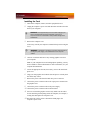
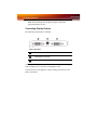
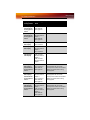
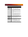
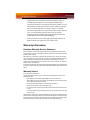
1
FireGL X3-256
TM
User’s Guide
P/N 137-50048-20
ATI
ii
Copyright © 2004, ATI Technologies Inc. All rights reserved.
ATI and ATI product and product feature names are trademarks and/or registered trademarks of ATI
Technologies Inc. All other company and/or product names are trademarks and/or registered
trademarks of their respective owners. Features, performance and specifications are subject to change
without notice. Product may not be exactly as shown in diagrams.
Reproduction of this manual, or parts thereof, in any form, without the express written permission of
ATI Technologies Inc. is strictly prohibited.
Disclaimer
While every precaution has been taken in the preparation of this document, ATI Technologies Inc.
assumes no liability with respect to the operation or use of ATI hardware, software or other products
and documentation described herein, for any act or omission of ATI concerning such products or this
documentation, for any interruption of service, loss or interruption of business, loss of anticipatory
profits, or for punitive, incidental or consequential damages in connection with the furnishing,
performance, or use of the ATI hardware, software, or other products and documentation provided
herein.
ATI Technologies Inc. reserves the right to make changes without further notice to a product or system
described herein to improve reliability, function or design. With respect to ATI products which this
document relates, ATI disclaims all express or implied warranties regarding such products, including
but not limited to, the implied warranties of merchantability, fitness for a particular purpose, and noninfringement.
Documentation Updates
ATI is constantly improving its product and associated documentation. To maximize the value of your
ATI product, you should ensure that you have the latest documentation. ATI’s documentation contains
helpful installation/configuration tips and other valuable feature information.
iii
L
IMPORTANT SAFETY INSTRUCTIONS
• Read Instructions - All the safety and operating instructions should
be read before the product is operated.
• Retain Instructions - The safety and operating instructions should
be retained for future reference.
• Heed Warnings - All warnings on the product and the operating
instructions should be adhered to.
• Compatibility - This option card is for use only with IBM AT or
compatible UL Listed personal computers that have Installation
Instructions detailing user installation of card cage accessories.
• Grounding - For continued protection against risk of electric shock
and fire, this accessory should be installed only in products equipped
with a three-wire grounding plug, a plug having a third (grounding)
pin. This plug will only fit into a grounding-type power outlet. This is a
safety feature. If you are unable to insert the plug into the outlet,
contact your electrician to replace the obsolete outlet. Do not defeat
the safety purpose of the grounding-type plug.
• Secure Attachment - All card securement pins shall be completely
tightened as to provide continuous bonding between the option card
and the PC chassis.
• Lightning - For added protection for this product during a lightning
storm, or when it is left unattended and unused for long periods of
time, unplug it from the wall outlet, and disconnect the antenna or
cable system. This will prevent damage to the product due to
lightning and power-line surges.
• Power Lines - An outside antenna system should not be located in
the vicinity of overhead power lines or other light or power circuits, or
where it can fall into such power lines or circuits.
• Antenna Installation - When installing an outside antenna system,
extreme care should be taken to keep from touching such power lines
or circuits, as contact with them may be fatal.
iv
v
Table of Contents
Getting Started. . . . . . . . . . . . . . . . . . . . . . . . . . . . . 1
System Requirements
Before You Begin
Record Your Serial and Part Numbers
Update Your AGP Chipset Drivers
Uninstall Previous Graphics Card Drivers
2
2
2
3
4
Installing Hardware . . . . . . . . . . . . . . . . . . . . . . . . . 7
Quick Installation
Detailed Installation
Installing the Card
Connecting Display Devices
7
7
9
10
Installing Software. . . . . . . . . . . . . . . . . . . . . . . . . 15
HYDRAVISION™ Multi-monitor Management
Installing Drivers and Software in Windows®
Software Installation Prerequisites
Monitor Configuration
Reinstalling Drivers
15
15
15
17
18
Display Properties . . . . . . . . . . . . . . . . . . . . . . . . . 19
ATI Displays Tab
Dynamic Display Reassignment
ATI Color Tab
Hotkeys
ATI Options Tab
ATI Configuration Tab
ATI Advanced Settings Tab
19
21
21
24
26
27
29
Reference . . . . . . . . . . . . . . . . . . . . . . . . . . . . . . . . 33
Troubleshooting
General Problems
Customer Care
Disclaimer
Warranty Information
Hardware Warranty Service Statement
Warranty Service
33
34
36
37
38
38
38
vi
Limitations
Getting Additional Accessories
Compliance Information
FCC Compliance Information
Industry Canada Compliance Statement
CE Compliance Information
Informations de conformité de la CE
Electrical Safety
VCCI Class B ITE Compliance Information
MIC Certification Information
BSMI Certification Information
39
39
39
40
40
40
41
41
41
41
42
1
CHAPTER 1:
Getting Started
Your ATI FireGL™ card is an advanced workstation 3D graphics card
based on a high-bandwidth, parallel pipeline geometry and rendering
architecture. The card delivers workstation-class performance to designers,
engineers, and animators, and runs the latest OpenGL® and Microsoft®
DirectX® applications.
Features of your FireGL™ workstation graphics card:
• Real-time photo-realistic rendering and animation.
• Stable and reliable software support for Windows® and Linux®
platforms.
• Optimized and certified for professional workstation applications.
• SMARTSHADER™ technology for creating complex visual
effects.
• SMOOTHVISION™ technology for advanced full-scene antialiasing.
2 System Requirements
System Requirements
Hardware
• Intel® Pentium® 4/Xeon®; AMD Athlon® 64/K7/XP or
compatible.
• 128 MB of system memory; 256 MB or more for best
performance.
• Motherboard with free AGP 8X/4X slot and correct
chipset driver.
• CD-ROM drive (required for installation software).
• 350 watt or greater power supply (recommended).
Operating
System
• Windows® 2000 with Service Pack 1 (or higher).
• Windows® XP Home or Pro with Service Pack 1 (or
higher).
• Linux® XFree86 4.X.0.
Monitor
• High-resolution MultiSync or multi-frequency monitors
or other VGA monitors.
• Digital flat-panel (DFP) displays or digital CRT
displays.
Before You Begin
Before you begin installing your FireGL™ product, please do the
following.
Record Your Serial and Part Numbers
The serial number and 102 part number on the graphics card are required
for registration. They are located on a sticker on the back of the card.
Write these numbers down before installing your new ATI product.
Before You Begin 3
Serial and Part Numbers
X
Serial number (S/N)
Y
102 part number (P/N)
Update Your AGP Chipset Drivers
Your new ATI FireGL™ card uses the AGP bus, and so it requires not only
display drivers, but also drivers that enable AGP functionality for the
motherboard chipset.
To ensure a successful installation of your new ATI graphics card, you
must make sure that your have installed the latest AGP chipset drivers
before replacing your current graphics card.
How to determine the motherboard chipset on your system
1
Open the Control Panel from the Start Menu and select System; in
Windows® XP’s Category View, System can be found under
Performance and Maintenance.
2
In the System Properties dialog, select the Hardware tab.
3
Select Device Manager.
4
From the Device Manager tree view, expand the System Devices
branch.
5
Scroll through the list of system devices until you find a listing for the
AGP controller.
These drivers may be referred to using any of the following names:
• AGP Driver
• AGP Miniport
4 Before You Begin
•
•
•
•
AGP VXD Driver
Chipset Driver
GART Driver
VGART
Often you will see the name of a motherboard chipset in connection
with these terms. For example:
• ALi GART Driver
• AMD AGP Miniport
• Intel VGART
• VIA AGP Driver
The chipset manufacturer’s name will appear as part of the device
name.
Once you have determined the chipset manufacturer for your motherboard,
obtain and then install the latest AGP drivers from that manufacturer’s Web
site.
L
WARNING - Installing the wrong AGP chipset drivers may prevent
you from successfully launching Windows®. Make sure that the
drivers you install are designed to function correctly with your
motherboard. If you are uncertain, please consult with your
motherboard manufacturer for advice.
For your convenience, here is a list of common motherboard
manufacturers:
VIA Technologies
www.viaarena.com
Acer Laboratories (ALI)
www.ali.com.tw
Silicon Integrated Systems
(SIS)
www.sis.com
Advanced Micro Devices (AMD)
www.amd.com
Intel Technologies
support.intel.com
General Motherboard/chipset
information
www.motherboards.org
Uninstall Previous Graphics Card Drivers
To ensure the successful installation of your new FireGL™ card, you must
uninstall the drivers for the existing graphics card before removing it from
your computer.
Before You Begin 5
To uninstall previous drivers
With your current graphics card still in your computer:
1
Close all applications that are currently running.
2
Navigate to the Control Panel and select Add/Remove Programs.
3
Select your current graphics card drivers and select Add/Remove.
The wizard will help you remove your current display drivers.
Note: If the previously installed graphics card has any additional
software installed, it should also be removed at this point.
4
Restart your system after the drivers have been removed.
6 Before You Begin
Quick Installation 7
CHAPTER 2:
Installing Hardware
This chapter will guide you through the physical installation of your
FireGL™ card.
Quick Installation
Experienced users and system administrators can follow these brief
instructions for installing the FireGL™ card in the shortest possible time.
To perform a quick installation
1
Uninstall the drivers and software for your old graphics card if you
have not already done so.
Note: If you are using a motherboard containing an on-board
graphics solution and do not intend to use it as part of a multiple
monitor display, disable it.
2
Shut down and disconnect your computer system.
3
Remove any previously installed card.
4
Install your new FireGL™ card.
5
Reassemble and connect your computer system.
6
Install the FireGL™ drivers and configuration software from the ATI
Installation CD-ROM by doing one of the following:
• Run through the automatic ATISETUP utility; or
• Start > Run > X:\ATISETUP.EXE (where X is the drive letter of
your CD-ROM drive).
Detailed Installation
The following instructions will take you step by step through the
installation of your new FireGL™.
8 Detailed Installation
FireGL™ Power Connections Diagram
X
FireGL™Graphics Card
Y
Power Supply
Z
Hard Drive
[
Power Cable Connector
\
4-Pin Power Connection
]
Power Extension Cable: Power Connector to Graphics Card
^
Power Extension Cable: Power Connector to Hard Drive
_
Power Extension Cable: Power Connector to Power Supply
`
Hard Drive
a
Power Connector to Hard Drive
Detailed Installation 9
Installing the Card
1
Turn off the computer, monitor, and other peripheral devices.
2
Unplug the computer’s power cord and disconnect all cables from the
back of your computer.
L
3
WARNING - Wait approximately 20 seconds after unplugging the
power cord before disconnecting a peripheral or removing a
component from the motherboard to avoid possible damage to the
motherboard.
Remove the computer cover.
If necessary, consult your computer’s manual for help in removing the
cover.
L
4
WARNING - Remember to discharge your body’s static electricity by
touching the power supply or the metal surface of the computer
chassis.
Unscrew or unfasten and remove any existing graphics card from
your computer.
Note: If your computer has an on-board graphics capability, you may
need to disable it on the motherboard. For more information, see your
computer documentation.
5
Locate the appropriate slot and, if necessary, remove the metal backplate cover.
6
Align your ATI graphics card with the slot and press it in firmly until
the card is fully seated.
7
Remove the power cable from the hard drive power connector.
8
Connect the power extension cable to the 4-pin power connection on
the graphics card.
9
Connect the power extension cable to the power supply .
10 Connect the power extension cable to the hard drive.
11 Screw in or fasten the graphics card securely. Make sure the cables
are not interfering with anything inside the computer (for example, a
cooling fan) and replace the computer cover.
12 Reconnect any cables you have disconnected and plug in the
computer’s power cord.
10 Detailed Installation
Note: Before turning your computer on again, connect the
appropriate display devices.
Connecting Display Devices
The following connections are available:
FireGL™ Baseplate
X
DVI-I Connection
Y
Stereographics Connection
Z
DVI-I Connection
Your FireGL™ card can connect one or two monitors, either DFP/digital
CRT or analog VGA, as well as a stereographics device.
You will need to use an adapter to connect analog VGA devices to the
DVI-I connections.
Detailed Installation 11
Using a VGA-to-DVI-I Adaptor
X
VGA Monitor Connector
Y
VGA-to-DVI-I Adaptor
Z
DVI-I Connection
Make sure all cables are securely connected before turning on your system.
Display Configurations
Your FireGL™ graphics card provides dual display functionality as well as
quad-buffered stereographics. The following table lists the different ways
you can connect displays to your card.
Display
Configuration
Connector(s)
Used
Comments
Single DFP
display
DVI-I connector
DFP - digital flat panel display.
Single CRT
display
VGA connector
with VGA-to-DVI-I
adapter
CRT- cathode ray tube analog display.
The DVI-I connection can support a
CRT display using the VGA-to-DVI-I
adapter.
Quad-buffered
stereographics
device
Quad-buffered
stereographics
A monitor must be connected for
quad-buffered stereographics to
function.
12 Detailed Installation
Display
Configuration
Connector(s)
Used
Comments
DFP display +
Quad-buffered
stereographics
device
DVI-I connector +
Quad-buffered
stereographics
CRT display +
Quad-buffered
stereographics
device
VGA connector
with VGA-to-DVI-I
adapter +
Quad-buffered
stereographics
DFP display +
DFP display
DVI-I connector +
DVI-I connector
CRT display +
DFP display
VGA connector
with VGA-to-DVI-I
adapter +
DVI-I connector
CRT display +
CRT display
VGA connector
with VGA-to-DVI-I
adapter +
VGA connector
with VGA-to-DVI-I
adapter
DFP display +
DFP display +
Quad-buffered
stereographics
device
DVI-I connector +
DVI-I connector +
Quad-buffered
stereographics
UNSUPPORTED - Quad-buffered
stereographics will not function
correctly if two monitors are enabled.
Disable one monitor before using
stereographics.
CRT display +
DFP display +
Quad-buffered
stereographics
device
VGA connector
with VGA-to-DVI-I
adapter +
DVI-I connector +
Quad-buffered
stereographics
UNSUPPORTED - Quad-buffered
stereographics will not function
correctly if two monitors are enabled.
Disable one monitor before using
stereographics.
CRT display +
CRT display +
Quad-buffered
stereographics
device
VGA connector
with VGA-to-DVI-I
adapter +
VGA connector
with VGA-to-DVI-I
adapter +
Quad-buffered
stereographics
UNSUPPORTED - Quad-buffered
stereographics will not function
correctly if two monitors are enabled.
Disable one monitor before using
stereographics.
Detailed Installation 13
Turning on the System
L
WARNING - Turn on your monitor before you turn on your
computer. Failure to do so could damage your monitor.
If you have properly installed your graphics card, operating system
messages will appear once the boot procedure is finished.
Your monitor will be running in a basic video mode. Higher refresh rates
are not available at this stage of the installation. Once you have installed the
FireGL™ drivers and software, you can use the Display Properties control
panel to adjust the video settings and configure multiple monitors.
14 Detailed Installation
HYDRAVISION™ Multi-monitor Management 15
CHAPTER 3:
Installing Software
This chapter will guide you through the installation of the drivers and
software associated with your FireGL™ card.
HYDRAVISION™ Multi-monitor
Management
The HYDRAVISION™ multi-monitor and desktop management software
will install automatically with the Express driver installation of the
ATISETUP utility. If you do not want to install HYDRAVISION™ , select
the Custom driver installation and clear the HYDRAVISION™ check
box.
For more information concerning HYDRAVISION™ , consult the user’s
guide included on the ATI Installation CD-ROM.
Installing Drivers and Software in
Windows®
You will need to install the FireGL™ drivers and software in the following
cases:
• After you have installed the card in your system.
• After you have reinstalled or upgraded your operating system.
This procedure applies to Windows® 2000 and Windows® XP.
L
Linux drivers and installation instructions are available from
ati.com/support
Software Installation Prerequisites
To install or remove the drivers, you must have administrator rights or be
logged on as a user with administrator rights.
16 Installing Drivers and Software in Windows®
Your operating system must be installed and running before you can install
the FireGL™ drivers. You must also have Service Pack 1 (or higher) for
Windows® 2000 or Windows® XP installed.
Make sure your monitor cable is properly attached before you begin.
Note: The installation dialog will display in English if your operating
system’s language is not supported.
To install ATI drivers and software
1
Start your system. When the Found New Hardware Wizard
comes up, click Cancel. When the System Settings Change
window asks you to restart your computer, click No.
2
Run the ATISETUP utility. The ATISETUP utility will start
automatically if you insert the ATI Installation CD-ROM into your
CD-ROM drive after the operating system has started. If your CDROM auto-run is not enabled or the ATISETUP utility does not start
automatically:
a)
b)
c)
d)
Click the Start button in the task bar.
Click Run.
Select ATISETUP.EXE from the root directory of the ATI
Installation CD-ROM.
Click OK.
3
Click Install under Software Install.
4
Click Next.
5
Click Yes to the license agreement. ATI Easy Install will start the
Installation Wizard.
6
Follow the wizard’s on-screen instructions to complete the
installation.
Note: The Express installation option is recommended. The
HYDRAVISION™ multi-monitor and desktop management software
will automatically be installed, along with the ATI driver, by selecting
this option. Not all software components are installed using the
Express installation. Custom installation allows you to select
individual software components for installation.
7
When the Setup complete message appears, select Yes, I want to
restart my computer now and click Finish.
Monitor Configuration 17
8
After the system reboots, the Found New Hardware message may
display the Digital Signature Not Found message. Click Yes or
Continue to complete the driver installation.
Monitor Configuration
Once the drivers and software have been installed, you can configure your
monitor.
To configure your primary display
1
Navigate to the Control Panel and choose Display or right-click on
the desktop and choose Properties.
2
Choose the Settings tab and select a screen resolution and color
depth that best suit your requirements and your monitor’s
performance.
3
Click the Advanced button and select the Monitor tab.
4
Choose a refresh rate from the drop-down list.
L
5
WARNING - Choosing a refresh rate unsupported by your monitor
may damage your monitor. Consult your monitor’s documentation if
necessary.
Click OK until you return to the desktop.
To set up a multi-monitor display
1
From the Start menu click Control Panel, then Display. Click the
Settings tab to access the basic multi-monitor configuration settings.
Note: ATI software provides many additional configuration features
that can be accessed by clicking the Advanced button from the
Display Properties > Settings tab.
2
Select the Monitor icon identified by the number 2.
3
Click Extend my Windows desktop onto this monitor.
4
Set the Screen Resolution and Color Quality as appropriate for the
second monitor. Click Apply or OK to apply these new values.
• Refer to your Windows online help and documentation for
further information on using the Settings tab.
18 Reinstalling Drivers
Note: When you use multiple monitors with your FireGL™ card,
one monitor will always be Primary. Any additional monitors will be
designated as Secondary.
Reinstalling Drivers
The software installation procedure detailed in this chapter describes how
to install the drivers for your graphics card after you have installed a new
card for the first time and have rebooted your computer.
If you are installing the graphics card drivers in a special working scenario,
such as if you have reinstalled your operating system or want to perform a
manual reinstallation.
To reinstall drivers using the ATISETUP utility
You can always install the drivers using the ATISETUP utility on the ATI
Installation CD-ROM. The ATISETUP utility will start automatically if
you insert the ATI Installation CD-ROM into your CD-ROM drive after the
operating system has started. If your CD-ROM auto-run is not enabled or
the ATISETUP utility does not start automatically, perform the following
actions:
1
Click the Start button in the task bar.
2
Select Run.
3
Browse to ATISETUP.EXE on the root directory of the ATI
Installation CD-ROM and click OK.
To manually reinstall drivers
To manually reinstall drivers, when prompted for a driver installation CD,
insert the ATI Installation CD-ROM and browse to the drivers
subdirectory.
ATI Displays Tab 19
CHAPTER 4:
Display Properties
This chapter describes how to use the advanced display, multiple-monitor,
and 3D graphics features in ATI’s Display Properties options.
ATI Displays Tab
The ATI Displays tab provides control over multiple-monitor features.
Here you can enable/disable display devices and swap the assignment of
Primary and Secondary displays.
The Displays Tab
20 ATI Displays Tab
ATI Displays Tab
Scheme
Displays the drop-down list of available display-device
configurations that have previously been created. New
configurations can be entered here and then saved using
the Save button.
Hotkey
Associates a hotkey with a scheme. To input the hotkey,
highlight the field and press the appropriate key
combination on your keyboard.
Display
Configuration
button
These are the buttons that contain the name of the
devices that can be connected to your graphics card, such
as Monitor, Panel, FPD, TV or YPrBr. Clicking on any of
these buttons opens further options to refine your display
on that device.
Only the type of devices supported by your graphic card
will be displayed as valid options.
If the text on the button is greyed out, that device is not
currently connected to your graphics card.
Save button
Saves display-device configuration schemes.
Delete button
Deletes display-device configuration schemes.
Display buttons
Enables or disables a display device; they also indicate
whether a device is enabled or disabled.
To enable or disable a display
If the enable/disable button is green, it indicates the device is enabled. If it
is red, it indicates the device is disabled. If the button is greyed out, the
device is not an option. For example, if there is only one monitor
connected, all buttons will be grey.
1
Click the enable/disable button
want to enable/disable.
2
Click OK or Apply to save the changes.
for the display device you
Note: Due to power restrictions, you can normally only have two
devices active at the same time; for example, two monitors or a
monitor and a TV.
To save a display-device scheme
Display-device selections can be saved as a scheme for quick recall.
ATI Color Tab 21
1
Click the enable/disable button
want to have active.
2
Type a name into the Scheme drop-down list field.
3
Click Save to save the scheme.
for the display devices you
Dynamic Display Reassignment
You can change the assignment of your Primary and Secondary display on
the fly, without rebooting. If you have more than one display device
available and have the proper adapters or connectors, you can plug it in to
your FireGL™ graphics card in order to view or extend your desktop
display to that device.
Note: Before you can change the assignment of the Primary display,
at least one Secondary display and the Extended Desktop mode must
be enabled. Extended Desktop mode is enabled through the
Windows® Display Property dialog, under Settings. For more
information, consult your Windows® documentation.
To assign your Primary monitor
1
Click the buttons to assign the Primary monitor:
• Clicking the
button will reassign the Primary and Secondary
monitors. Clicking the
button creates a clone or mirror image
of the Primary display onto the Secondary display.
2
Click OK or Apply to save the changes.
ATI Color Tab
The ATI Color tab allows you to configure Gamma, Brightness, and
Contrast color settings for both your desktop and full screen 3D
environments. You can also save settings to a color profile for easy recall.
In addition, you can assign unique hotkey combinations that allow you to
adjust Gamma, Brightness, and Contrast color settings within your fullscreen 3D applications.
22 ATI Color Tab
The Color Tab
ATI Color Tab
Desktop radio
button
Select Desktop to configure your desktop color settings.
Full Screen 3D
radio button
Select Full Screen 3D to configure the color settings for
your 3D applications. Note that the configured settings will
only be apparent within a full-screen 3D application
environment.
Profiles for
Indicates whether the profiles in the drop-down list are for
your Desktop or a full-screen 3D environment.
Profiles dropdown list
Lists all of the Desktop or Full Screen 3D profiles that you
have saved. Selecting a profile from the list loads those
custom color settings for the relevant environment. To
create a new profile, simply type in a name and click Save.
ATI Color Tab 23
ATI Color Tab
Save button
Saves your current color settings to a Desktop or Full
Screen 3D profile, using the name you specified in the list
box. To restore these settings later, simply select the
Profile name from the list and click Apply or OK.
Delete button
Deletes the profile that is selected in the Profiles list box.
All Colors
checkbox
Adjusts the Gamma, Brightness or Contrast for Red,
Green, and Blue simultaneously. Note that any individual
color settings in effect are lost if All Colors is selected; the
color settings revert back to the last-known All Colors
settings.
Red, Green, and
Blue radio
buttons
Selects the active color component (Red, Green, or Blue)
whose values will be adjusted by the Gamma, Brightness,
and Contrast sliders. Note that any individual color settings
made are lost if you subsequently select All Colors.
Gamma slider
Increases or decreases the gamma correction of your
Desktop or full-screen 3D application. Changing the
gamma alters the curvature of the color curve.
Brightness slider
Increases or decreases the color brightness of your
Desktop or full-screen 3D application. Changing the
brightness adjusts the vertical position of the color curve.
Contrast slide
Increases or decreases the color contrast of your Desktop
or full-screen 3D application. Changing the contrast
adjusts the slope of the color curve.
Reset buttons
Restores an individual slider setting to its default value.
Click Apply or OK to save.
Color preview
box
The color image indicates visually how the Gamma,
Brightness and Contrast sliders affect the final color
settings of your display device. In Desktop mode, clicking
on this with your mouse pointer will change the image.
Hotkeys button
Opens the Color Hotkeys Settings dialog. There you can
assign hotkeys for adjusting your color settings within a
full-screen 3D application environment. To activate this
button, you must select the Full Screen 3D radio button.
Defaults button
Restores all of the color settings to the default values.
Click Apply or OK to save.
Color Curve box
The color curve indicates mathematically how the
Gamma, Brightness and Contrast sliders affect the final
color settings of your display device.
24 ATI Color Tab
To create a Desktop or Full Screen 3D profile
1
Choose either the Desktop or Full Screen 3D radio button, as
desired.
2
Adjust the Gamma, Brightness, and Contrast sliders to the desired
settings, either individually or using the All Colors checkbox.
3
Type a profile name in the Profile list box.
4
Click Save.
To apply the settings for a specific Desktop profile
1
Choose the Desktop radio button.
2
Select the profile name from the drop-down list box.
3
Click Apply or OK.
To apply the settings for a Full Screen 3D profile
1
Choose the Full Screen 3D radio button.
2
Select the profile name from the drop-down list box.
3
Click Apply or OK.
4
Start your 3D application in full-screen mode.
Hotkeys
Some 3D applications automatically load their own color settings rather
than those set through the ATI Color tab. To use custom settings, you can
preconfigure hotkey combinations to either adjust the individual color
properties or apply profiles you have created, once the 3D application is
running.
ATI Color Tab 25
The Color Hotkeys Settings dialog
To access the Color Hotkeys Settings dialog
1
Select the Full Screen 3D radio button.
2
Click the Hotkeys button to access the Color Hotkeys Settings
dialog.
The easiest way to apply your own color settings from within a full screen
3D application is to create a Full Screen 3D profile and save it, assign
hotkeys for the “Load Current Profile” action through the Hotkeys dialog,
make sure that the profile you prefer is selected from the drop-down list
box, and click OK. Once inside the 3D application, use the hotkeys to
trigger the profile.
Some 3D applications allow you to switch easily between full-screen mode
and windowed mode and do not load their own color settings. In windowed
mode, you can make slider adjustments or select a different profile on the
Color tab, then switch back to full-screen mode to see the effects
immediately.
26 ATI Options Tab
ATI Options Tab
The ATI Options tab provides detailed driver information and access to
your graphics card’s versioning and specifications. You can also enable or
disable the ATI taskbar icon from this dialog.
The Options Tab
ATI Options Tab
Version
Information
Shows the driver build version.
Details button
Gives access to the Details tab, which lists the card’s
hardware details and driver information.
Reactivate all
warning
messages
Reactivates any disabled graphics warning messages.
ATI Configuration Tab 27
ATI Options Tab
Enable ATI
taskbar icon
application
Enables/disables the ATI taskbar applications and
removes the ATI icon from your system tray.
Show ATI icon on
taskbar
Removes/replaces the ATI icon from the system tray
without disabling the ATI icon applications.
Disable quick
resolution feature
The quick resolution feature is accessible by left-clicking
the ATI icon in the system tray. Checking this option
disables this feature.
Reduce DVI
frequency on
high-resolution
Resolves display corruption or no image at high
resolutions (for example 1280x1024 @75Hz) using a
digital DVI display. This setting has no effect when using a
DVI-I-to-VGA adapter.
Alternate DVI
operational mode
Use this option if you are experiencing display corruption
on your DVI flat panel display.
ATI Configuration Tab
The Configuration Tab enables you to customize display profiles for
individual applications. Typically, you would change these settings for one
or more of the following reasons:
• Diagnostic purposes.
• Fine-tuning a specific application/system configuration.
• Specific settings recommended by your hardware or software
documentation.
• Tuning your application/system environment for best performance
and memory usage.
28 ATI Configuration Tab
The Configuration Tab
Activating a configuration profile
The Configuration Profiles listbox displays a number of common
applications whose optimal configuration profile are factory-set by default.
To activate a particular profile, select the application name from the list and
click Apply. This will add the information to the necessary Windows
registry settings. If prompted, restart Windows.
If you subsequently experience problems with your application, or if you
want to try to optimize the performance of your system on specific
applications, modify your configuration settings accordingly.
Adding a new application profile
Click the Add button in the Configuration Profiles section and enter the
name of the new application for which you want to set the configuration
parameters.
ATI Advanced Settings Tab 29
Modifying the configuration parameters
To change the configuration settings of a specific application, select the
name of that application from the Configuration Profiles listbox. Click
the Modify button. Now select or clear the rest of the configuration controls
on this tabbed dialog to obtain the desired display parameters for the
selected application.
To remove the selected configuration profile completely, select the name
of the application from the Configuration Profiles listbox click Delete.
Note: You cannot delete the factory-set configuration profiles.
Click the Apply or OK button to enable your Configuration settings.
Configuration Settings
Enable 8-Bit
double-buffered
Overlay Planes
A default setting that uses 8 bits of each 32-bit frame
buffer pixel as double-buffered overlay planes.
Force copy swap
A default setting that forces blit copy from the back-tofront buffer. This copies pixels quickly from memory to the
screen, reducing flicker and increasing the frame rate.
Note that OpenGL® buffer swaps are implemented using
a back-to-front buffer instead of a screen flip.
Wait for vertical
retrace
The buffer swap is ‘synched’ to the refresh rate of the
monitor. Enabling this will lower the frame rate but reduce
visual artifacts such as tearing. Disabling allows your
application to run at the highest possible frame rate,
regardless of the monitor’s refresh rate, which is typically
less than the frame rate at which the application will run.
ATI Advanced Settings Tab
The Advanced Settings tab enables you to apply ATI’s
SMOOTHVISION™ technology for full-scene anti-aliasing, and to utilize
stereo shutter glasses for visualizing immersive 3D-stereo display (only
available for those FireGL™ cards equipped with a stereo video
connector).
SMOOTHVISION™ improves image quality by removing jagged edges
(anti-aliasing) from 3D images, resulting in smoother, more natural looking
objects.
30 ATI Advanced Settings Tab
The Advanced Settings Tab
How to Use SMOOTHVISION™
The Application preference setting provides OpenGL® and Direct 3D®
applications with the ability to enable anti-aliasing automatically. If an
application does utilize an anti-aliasing setting, it is disabled. This option
results in high-quality images at the price of a negligible reduction in the
application’s performance.
When Always on is enabled, you can apply anti-aliasing using different
sample patterns and sample points such as 2X or 4X. Moving the slider to
the right increases sampling to provide the most realistic 3D image, at the
cost of overall 3D performance.
Note: The Always on setting overrides an application’s anti-aliasing
setting.
ATI Advanced Settings Tab 31
How to Use Stereo Glasses with Your FireGL™ Card
The Enable Quad Buffer Stereo option requires a stereographics
connection on your FireGL™ card. Enabling this feature while using
compatible stereo glasses and applicable software provides an immersive
3D-stereo display.
L
The Enable Quad Buffer Stereo option is only available for graphics
cards that come with a stereographics connection.
32 ATI Advanced Settings Tab
Troubleshooting 33
CHAPTER 5:
Reference
This chapter offers troubleshooting tips and provides customer-care,
warranty, and compliance information.
Troubleshooting
The following troubleshooting tips may help if you experience problems.
ATI’s documentation contains helpful installation/configuration tips and
other valuable feature information. Please contact your dealer for more
advanced troubleshooting information.
More troubleshooting information can be found on the ATI Web site.
Please visit ati.com and select Customer Care.
34 Troubleshooting
General Problems
Problem
Possible Solution
Computer Does
Not Boot-Up
Properly
• Verify that the installation instructions were properly
followed.
• Check that the card is properly installed in your
system and connected to your monitor.
• If you have problems during start-up, restart your
computer in Safe Mode.
While starting Windows® 2000 and Windows® XP,
press and hold F8 until you see the Windows®
Advanced Options Menu. Use the arrow keys to select
Safe Mode, and press Enter.
• Check the system configuration utility of your
operating system for the interrupt assignments.
• Contact ATI’s Customer Care or your local technical
support.
No Display
• Check that the card is seated properly in its expansion
slot.
• Ensure that the monitor cable is securely fastened to
the card.
• Make sure that the monitor and computer are plugged
in and receiving power.
• If necessary, disable any built-in graphics capabilities
on your mother board. For more information, consult
your computer’s manual or manufacturer. (Note:
some manufacturers do not allow the built-in graphics
to be disabled or to become the secondary display.)
• Make sure that you selected the appropriate monitor
when you installed your enhanced driver.
Screen Defects
Appear
• Check if your monitor supports the resolution,
horizontal (kHz) and vertical (Hz) refresh rates as
required by the graphics card.
• Check your current resolution, refresh rate, and color
depth settings in the Settings and Monitor tabs in
your Display Properties dialog.
Warning! Ensure that both video card and monitor
support resolution and refresh rates you select.
Incompatible resolution/refresh rate selection may result in
monitor damage. Refer to your monitor's documentation
for recommended resolutions and refresh rates.
Troubleshooting 35
Problem
Possible Solution
Off-Center
Screen Image,
Odd Colors or No
Picture
• Try adjusting the brightness, sharpness, contrast, and
color balance controls of your monitor.
• Try adjusting the centering and positioning controls of
your monitor to position the picture on the screen.
Note: The Screen Position settings in Display
Properties > Advanced > Displays > Adjustments
tune the position of the picture on the screen via the
video signal.
• Set the monitor's RGB inputs (and sync switches, if
this option is available) to 75 Ohms, with the sync set
to external.
• DFP monitor users: Make sure that the DVI plug of
your monitor data cable is digital-only (DVI-D) - but not
integrated analog/digital (DVI-I). Refer to your
monitor's documentation and contact your supplier or
the manufacturer of the DFP monitor for information
on how to obtain a suitable data cable plug.
Operating
System Warns
that Video Card
Isn’t Properly
Configured
• Check the driver installation and make sure that all
software is correctly loaded corresponding to your
operating system and applications.
• Reinstall the ATI drivers for your FireGL™ card.
Stereo Glasses
Not Working
• Your stereo glasses must be connected to the card
when you start your computer.
• Select a refresh rate of 120 Hz in the Monitor tab
available from Display Properties > Advanced.
• Enable the Quad Buffer Stereo option in the
Advanced Settings tab of the Display Properties.
36 Customer Care
Problem
Possible Solution
Bus Address or
Interupt Conflicts
• It is necessary to ensure that the I/O and memory
addresses reserved for the graphics board are not
used by other hardware devices.
• The integrated on-board VGA controller of your
FireGL™ card uses the following addresses (hex):
I/O Address:
Standard VGA I/O: 3B0-3DF
Memory Addresses:
Video RAM: A000-BFFF
Video ROM: C000-C7FF
Note: You cannot change the addresses of your
FireGL™ card. In case of an address conflict, try to
modify the I/O address of the add-on card that causes
the conflict.
• To support the special graphics processor on the
FireGL™ card, the system BIOS should automatically
assign a system interrupt to the slot where the card is
installed. However, there may be problems if your
graphics card does not receive an interrupt or a
system interrupt is used for more than one device. In
case of problems check the system configuration utility
of your operating system for the interrupt assignments.
Customer Care
If you require further assistance with your product, the following Customer
Care options are available to you:
Service
Access
Additional Info
Online
ati.com/online/
customercare
• Always available.
• Complimentary.
Telephone
US & Canada
1-866-284-2093
• 9:00AM - 7:00PM EST.
Monday to Friday.
• Complimentary for registered
users.
• Toll-free.
Customer Care 37
Service
Access
Additional Info
Telephone
Europe
+49-1803-347345
• 10:30AM - 7:00PM GMT.
Monday to Friday.
• Complimentary for registered
users.
• International and local toll
charges to Germany will apply.
• Support available in English,
German, and French.
Telephone
Argentina
+0800-333-5277
• 9:00AM - 5:30PM EST.
Monday to Friday.
• Toll-free
• Support available in English,
Spanish, and Portuguese.
Telephone
Brazil
+0800-891-9068
• 9:00AM - 5:30PM EST.
Monday to Friday.
• Toll-free
• Support available in English,
Spanish, and Portuguese.
Telephone
Mexico
+001800-514-3276
• 9:00AM - 5:30PM EST.
Monday to Friday.
• Toll-free
• Support available in English,
Spanish, and Portuguese.
Telephone
Other Latin
American
Countries
+1-905-882-3277
• 9:00AM - 5:30PM EST.
Monday to Friday.
• Complimentary
• International and local toll
charges to Canada will apply.
• Support available in English,
Spanish, and Portuguese.
Mail
ATI TECHNOLOGIES INC.
Attention: Customer Care
1 Commerce Valley Drive East
Markham, Ontario
Canada L3T 7X6
• Complimentary.
Disclaimer
ATI Customer Care will work to resolve your issue and help you to get your
product up and running. If your issue is not resolved, our technicians will
determine whether the difficulty you are experiencing is the result of the
product, whether your product contains a defect, and whether your product
should be returned to ATI for warranty service.
38 Warranty Information
• ATI Customer Care is unable to assist with refunds, returns, or
exchange-specific inquiries. If resolving the problem being
experienced is critical to your decision to keep the product, it is your
responsibility to ensure that you know and are within the period of
time your reseller will allow for refunds, returns, or exchange.
• ATI is not responsible for any expense incurred accessing Customer
Care. It is expected that customers will review the expense
associated with the available support options and will choose the
method that best meets their needs and budget.
• ATI Customer Care reserves the right to limit support options for
products that are not registered or are at End of Life.
Warranty Information
Hardware Warranty Service Statement
ATI Technologies Inc. warrants to the original purchaser of the hardware that the product is in good
working condition, according to its specifications at the time of shipment, for a period of three years from
the date of original purchase.
Should the product, in ATI’s opinion, malfunction within the warranty period, ATI will, at its discretion,
repair or replace the product upon receipt with an equivalent. Any replaced parts become the property
of ATI. This warranty does not apply to the software component of the installation, usage not in
accordance with product specifications and instructions, natural or personal disaster, or unauthorized
alterations, repairs, or modifications.
Proof of purchase may be required, if doubt exists regarding warranty eligibility. Late model products are
assumed to be under warranty. ATI accepts ordinals, photocopies and faxes as proof of purchase when
required
Warranty Service
For warranty service instructions visit:
ati.com/online/warranty or contact one of our Customer Service Representatives using one of the
aforementioned means.
• Before shipping any unit for repair, obtain an RMA number for warranty service.
• When shipping your product, pack it securely, show the RMA and serial number of the product
on the outside, and ship prepaid and insured.
• ATI will not be held liable for damage or loss to the product in shipment.
• Standard warranty service consists of repair upon receipt.
• ATI reserves the right to replace the product with a serviced product at their sole discretion at
any time.
• You are responsible for the cost of shipping the product to ATI. ATI plays the cost of returning
the product to you.
Products which are repaired under warranty are guaranteed for the remainder of the original warranty
period. Repairing or exchanging a product does not start a new warranty period. If, at the time of repair,
a product is already “out of warranty” or within the last 90 days of the warranty period, ATI will guarantee
the repair for the full 90 days. All other terms and conditions of the original warranty apply.
Getting Additional Accessories 39
Limitations
• This warranty is valid only if the online Product Warranty Registration form at:
ati.com/online/registration
is successfully submitted within 30 days of purchase of said product.
• All warranties for this product, expressed or implied, will expire three (3) years* from date of
original purchase.
• All accompanying cables and accessories are warranted for 90 days.
• No warranties for this product, expressed or implied, shall extend to any person who purchases
the product in a used condition.
• The liability of ATI in respect of any defective product will be limited to the repair or replacement
of such product. ATI may use new or equivalent-to-new replacement parts. Defective product
will be sent in for repair or replacement only. ATI makes no other representations or warranties
as to fitness for a particular purpose, merchantability or otherwise in respect of the product. No
other representations, warranties or conditions, shall be implied by statute or otherwise. In no
event shall ATI be responsible or liable for any damages, including but not limited to the loss of
revenue or profit, arising:
• From the use of the product, as a result of any event, circumstance, action or abuse beyond the
control of ATI; whether such damages be direct, indirect, consequential, special or otherwise
and whether such damages are incurred by the person to whom this warranty extends or a third
party
• From the loss of use of the product, as a result of any event, circumstance, action or abuse
beyond the control of ATI; whether such damages be direct, indirect, consequential, special or
otherwise and whether such damages are incurred by the person to whom this warranty extends
or a third party.
• Unauthorized repairs to an ATI board level product will void the warranty offered by ATI
Technologies. ATI reserves the rightto refuse to service any product which has been altered,
modified, or repaired by non-ATI service presonnel.
Getting Additional Accessories
Additional and replacement cables, installation CD-ROMs, manuals, and
other accessories for ATI products can be purchased from the online ATI
store at:
ati.com/online/accessories.
Compliance Information
This section details the compliance information for this product.
40 Compliance Information
FCC Compliance Information
This FireGL™ product complies with FCC Rules part 15. Operation is subject to
the following two conditions
• This device may not cause harmful interference, and
• This device must accept any interference received, including interference that
may cause undesired operation.
This equipment has been tested and found to comply with the limits for a Class B digital device, pursuant
to Part 15 of the FCC Rules. These limits are designed to provide reasonable protection against harmful
interference in a residential installation. This equipment generates, uses and can radiate radio frequency
energy and, if not installed and used in accordance with manufacturer's instructions, may cause harmful
interference to radio communications. However, there is no guarantee that interference will not occur in
a particular installation. If this equipment does cause harmful interference to radio or television
reception, which can be determined by turning the equipment off and on, the user is encouraged to try
to correct the interference by one or more of the following measures:
• Re-orient or relocate the receiving antenna.
• Increase the separation between the equipment and receiver.
• Connect the equipment to an outlet on a circuit different from that to which the receiver is
connected.
• Consult the dealer or an experienced radio/TV technician for help.
The use of shielded cables for connection of the monitor to the graphics card is
required to ensure compliance with FCC regulations. Changes or modifications to
this unit not expressly approved by the party responsible for compliance could
void the user's authority to operate this equipment.
Industry Canada Compliance Statement
ICES-003 This Class B digital apparatus complies with Canadian ICES-003.
Cet appareil numérique de la Classe B est conforme à la norme NMB-003 du Canada.
For further compliance information:
ATI Research Inc.
4 Mount Royal Ave.
Marlborough, MA
01752-1976
USA
508-303-3900
CE Compliance Information
EMC Directive 89/336/EEC and amendments 91/263/EEC, 92/31/EEC and 93/68/EEC, Class B Digital
Device EN 55022:2003/CISPR 22 Class B, Limits and Methods of Measurement of Radio Interference
Characteristics Information Technology Equipment.
EN 55024:1998/CISPR 24:1997 +A1:2001 +A2:2003, Immunity of Information Technology Equipment
(ITE), including EN 61000-4-2, EN 61000-4-3, EN 61000-4-4, EN 61000-4-5, EN 61000-4-6
Compliance Information 41
Informations de conformité de la CE
Directive EMC 89/336/CEE et amendements 92/31/CEE et 93/68/CEE, pour dispositif numérique de
Classe B.
EN 55022:2003/CISPR 22:1997, - Classe B - Limites et méthodes de mesure des caractéristiques
d'interférences radiophoniques, Matériel des technologies de l'information.
EN 55024:1998/CISPR 24:1997 +A1:2001 +A2:2003, Norme sur l'immunité de matériel des
technologies de l'information, et comprenant EN 61000-4-2, EN 61000-4-3, EN 61000-4-4, EN 610004-5, EN 61000-4-6
Electrical Safety
Low Voltage Directive for TV-Tuner_Equipped products
73/23/EEC - The Low Voltage Directive
IEC 60950-1:2001, IEC 60950:1999, 3rd Edition - Safety of Information Technology Equipment
BS EN60950-1:2002, BS EN60950:2000, 3rd Edition UL 60950-1:2003, UL 60950:2000, 3rd Edition
CAN/CSA C22.2 No. 60950-1:2002, CAN/CSA C22.2 No. 60950-00, 3rd Edition (2000)
VCCI Class B ITE Compliance Information
MIC Certification Information
42 Compliance Information
BSMI Certification Information
43
Index
Numerics
102 part number
3D
full-screen
2
21
A
Advanced Settings tab
AGP drivers
chipset drivers
29
3
ATI taskbar applications
disabling 26, 27
enabling 26, 27
B
brightness
23, 24
21
color settings
C
card specification information
color
hotkeys
23
color preview
color settings
23
color settings
brightness 21
color preview 23
contrast 21, 23
desktop 22
gamma 21
Hotkeys 24
profiles 22
Color Tab 21
configuration
multiple monitors 17
primary monitor 17
Configuration Tab
contrast 23, 24
color settings
D
desktop
color settings
21
22
27
26
44
Direct 3D ® 30
display corruption
DVI 27
high resolution
27
displays
Hotkey 20
primary 19
scheme 20
secondary 19
Displays Tab 19
driver information
drivers
26
installing 16
reinstalling 18
uninstalling 5
DVI operational mode
F
full-screen 3D 21
G
gamma 23, 24
color settings
21
gamma correction
H
Hotkeys
color settings
24
23
HYDRAVISION™ 15,
L
Linux installation 15
O
OpenGL ® 30
Options Tab 26
P
primary display 19
primary monitor
assigning
profiles
color
22
21
27
16
45
R
registration 2
S
safety instructions iii
secondary display 19
serial number 2
SMOOTHVISION™ 30
stereographics
enabling 31
troubleshooting
35
system requirements
2
46
Addendum
Waste Electrical and Electronic Equipment (WEEE)
Directive Compliance
This product was manufactured by ATI Technologies Inc.