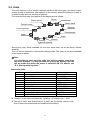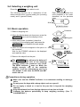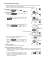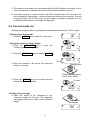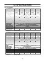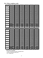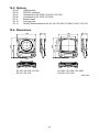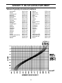
1
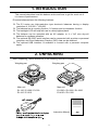
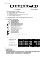
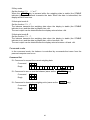
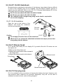
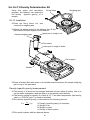
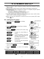
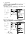
1WMPD4001917 This manual and Marks All safety messages are identified by the following, “WARNING” or “CAUTION”, of ANSI Z535.4 (American National Standard Institute: Product Safety Signs and Labels). The meanings are as follows: WARNING CAUTION A potentially hazardous situation which, if not avoided, could result in death or serious injury. A potentially hazardous situation which, if not avoided, may result in minor or moderate injury. This is a hazard alert mark. Note This manual is subject to change without notice at any time to improve the product. No part of this manual may be photocopied, reproduced, or translated into another language without the prior written consent of the A&D Company. Product specifications are subject to change without any obligation on the part of the manufacture. Compliance with FCC rules Please note that this equipment generates, uses and can radiate radio frequency energy. This equipment has been tested and has been found to comply with the limits of a Class A computing device pursuant to Subpart J of Part 15 of FCC rules. These rules are designed to provide reasonable protection against interference when this equipment is operated in a commercial environment. If this unit is operated in a residential area it might cause some interference and under these circumstances the user would be required to take, at his own expense, whatever measures are necessary to eliminate the interference. (FCC = Federal Communications Commission in the U.S.A.) Copyright 2009 CONTENTS 1. INTRODUCTION .............................................................................................................3 2. UNPACKING ...................................................................................................................3 3. PART NAMES AND FUNCTIONS ...................................................................................4 4. SETTING UP ...................................................................................................................5 4-1. Setting up your balance .................................................................................................................5 4-2. Power source.................................................................................................................................5 4-3. Breeze break .................................................................................................................................6 4-4. Storage ..........................................................................................................................................6 5. OPERATION....................................................................................................................7 5-1. Turn the power ON and OFF .........................................................................................................7 5-2. LCD backlight ................................................................................................................................7 5-3. Units ..............................................................................................................................................8 5-4. Selecting a weighing unit ...............................................................................................................9 5-5. Basic operation ..............................................................................................................................9 5-6. Counting mode (pcs) ...................................................................................................................10 5-7. Percent mode (%)........................................................................................................................11 6. COMPARATOR .............................................................................................................12 6-1. Setting example ...........................................................................................................................12 7. CALIBRATION ..............................................................................................................14 7-1. Calibration using a weight............................................................................................................14 7-2. Gravity acceleration correction ....................................................................................................16 8. FUNCTIONS..................................................................................................................17 8-1. Key operation ..............................................................................................................................17 8-2. Entering the function setting mode ..............................................................................................17 8-3. Setting example ...........................................................................................................................18 8-4. Storing weighing units..................................................................................................................19 8-5. Function list .................................................................................................................................20 9. OPTIONS.......................................................................................................................22 9-1. EJ-02 USB Interface ....................................................................................................................22 9-2. EJ-03 RS-232C serial interface ...................................................................................................22 9-3. EJ-07 / EJ-08 Underhook ............................................................................................................26 9-4. EJ-11 Breeze break .....................................................................................................................26 9-5. EJ-12 Carrying case ....................................................................................................................26 9-6. EJ-13 Density Determination Kit ..................................................................................................27 10. ID NUMBER AND GLP................................................................................................30 10-1. Setting the ID number................................................................................................................30 10-2. Output example .........................................................................................................................31 10-3. Calibration test using a weight ...................................................................................................32 1 11. MAINTENANCE ..........................................................................................................34 11-1. Notes on maintenance ...............................................................................................................34 11-2. Error codes ................................................................................................................................34 12. SPECIFICATIONS .......................................................................................................36 12-1. EJ series ....................................................................................................................................36 12-2. Other weighing units ..................................................................................................................37 12-3. Options ......................................................................................................................................38 12-4. Dimensions ................................................................................................................................38 GRAVITY ACCELERATION MAP .....................................................................................39 2 1. INTRODUCTION This manual describes how this balance works and how to get the most out of it in terms of performance. EJ series balances have the following features: The EJ series are high-resolution type electronic balances having a display resolution of 1/12,000 ~ 1/60,000. The balance has a counting function, % function and a comparator function. The backlight LCD will help with use in a dimly lighted place. The balance can be operated with an AC adapter, or 4 x “AA” size dry-cell batteries for cordless operation. The optional RS-232C serial interface can be connected with a printer or personal computer, and Good Laboratory Practice (GLP) data can be obtained. The optional USB interface is available to connect with a personal computer easily. 2. UNPACKING When unpacking, check whether all of the following items are included: Weighing pan Weighing pan Main unit Main unit EJ-120 / EJ-200 / EJ-300 EJ-410 / EJ-610 EJ-1500 / EJ-2000 / EJ-3000 EJ-4100 / EJ-6100 Instruction Manual 3 3. PART NAMES AND FUNCTIONS Battery indicator STABLE indicator NET indicator ZERO indicator ON:OFF ACAI indicator Comparator results STABLE Specific gravity Weighing units NET ZERO Weighing pan Round pan for key EJ-120 / EJ-200 / EJ-300 / EJ-410 / EJ-610. Spirit level LCD Leveling foot SAMPLE Calibration switch cover (bottom) PRINT UNITS RE-ZERO key key AC adapter jack key key EJ-02 / EJ-03 slot Battery cover Security slot (Use a security cable commercially available.) Turns the power on or off. Clears the display to zero (combined zero and tare). Held down to enter the function setting mode. Outputs the weight value to printer. pcs mode: Enters the sample unit weight storing mode. Stores a unit weight, 100% weight or other setting values to the balance. % mode: Enters the 100% weight storing mode. Switches the weighing units. 4 4. SETTING UP 4-1. Setting up your balance 1. Place the weighing pan on the main unit as shown in “2. UNPACKING”. 2. Adjust the level of the balance using the leveling feet. Use the spirit level to confirm. The bubble should be in the center of the circle. 3. Calibrate your balance before use. (See “7. CALIBRATION”) Balance location To measure correctly, to keep the balance in good condition, and to prevent hazards, observe the following: Do not install the balance in locations that are subject to excessive dust, breezes, vibration, large temperature fluctuations, condensation, or that may have magnetic fields. Do not install the balance on a surface that is soft or that may cause the balance level to shift. Do not install the balance in direct sunshine. Do not install the balance near heaters or air conditioners. Do not use an unstable AC power source. Do not install the balance in a place where combustible or corrosive gases may exist. Allow the balance to reach equilibrium with the ambient temperature before use. Switch the power ON at least half an hour before use so that the balance can warm up. When the balance is installed for the first time, or the balance has been moved, carry out calibration as described in “7. CALIBRATION” 4-2. Power source For the power source, the AC adapter or 4 x “AA” size dry-cell batteries can be used. When using the AC adapter AC adapter jack Use a stable power source. To use the AC adapter, insert the AC adapter plug into the AC adapter jack on the rear side of the EJ. When using the dry-cell batteries Prepare 4 x AA size (LR6 / R6P) dry cell batteries. The batteries are not included in the product, CAUTION Take great care of the polarity of batteries. The polarity marks are shown in the battery box. Replace used batteries with four new ones when “lb0” is displayed. Do not mix used and new batteries. Do not mix the battery type. It may cause damage to the batteries and the balance. The battery life depends on the ambient temperature, how to use and so on. 5 Remove batteries when the balance is not to be used for a long time. They may leak and cause damage to the balance. Damage due to battery leakage is not covered by the warranty. Installing batteries 1. Turn off the balance and disconnect the AC adapter if used. 2. Slide the battery cover off. 3. Push the battery box up to unhook and pull it out. 4. Insert new four batteries (LR6 / R6P / AA size) into the battery box, taking extreme care of the polarities. 5. Push the battery box into the balance as before. 6. Attach the battery cover. Battery cover Hook Battery box Hook Battery indicator turns on when the balance is operated by the batteries. It will change as the battery voltage decreases. New Æ Æ Æ Coming close to “lb0”. 4-3. Breeze break The optional breeze break is available. See “9-4. EJ-11 Breeze break”. 4-4. Storage The EJ series balance can stack on top of another when not in use. Do not stack more than 3 units. 6 5. OPERATION 5-1. Turn the power ON and OFF 1. Press the ON:OFF key to turn the power ON. STABLE Weighing units NET ZERO All of the symbols are displayed as shown above. (About units: Only the units available will be displayed.) The display turns off except for a weighing unit and the decimal point. The balance waits for the weighing data to become stable, and zero will be displayed with the ZERO indicator (power-on zero). The range for power-on zero is within ±10% of the weighing capacity around the calibrated zero point. If the power is switched ON while there is a load beyond this range, the balance will be tared to zero and the NET indicator and the ZERO indicator turn on. 2. Press the ON:OFF key again, and the power will be switched OFF. Auto-power off function It is possible to have the power automatically switched OFF, if zero is displayed for approximately 5 minutes. See “8-5. Function list” and set the function “poff”. 5-2. LCD backlight The LCD backlight will turn on when the weight value changes more than 4d (4 x min. display division) or any key operation is done. When the weight data becomes and stays stable for some moment, the backlight will automatically turn off. There is also a setting that the backlight is always on or off. For details, see the function setting “ltUp” of “Function list”. 7 5-3. Units The most common unit of weight used around the world is the gram, but there is often a need to shift to alternative units specific to the country where the balance is used or to select modes such as counting or percent. The units and the order they appear in the display are as follows: Pound Ounce (avoir) Metric carat Percent mode Momme Counting mode Pennyweight Gram Grain Newton Density (specific gravity) Among the units, those available for the user have been set at the factory before shipping. The unit can be selected in the function setting mode. The order of the units available is the same as above. Note It is possible to store only the units that will be actually used from the units available. It is also possible to specify the display unit that will be shown first when the power is switched ON. For details, see “8-4. Storing weighing units”. Conversion table Units oz lb ozt ct mom dwt GN t tl tl tl Name Ounce (avoir) Pound (UK) Troy ounce Metric carat momme Pennyweight Grain (UK) tola tael (Hong Kong general, Singapore) tael (Hong Kong jewelry) tael (Taiwan) Conversion to gram 28.349523125 g 453.59237 g 31.1034768 g 0.2 g 3.75 g 1.55517384 g 0.06479891 g 11.6638038 g 37.7994 g 37.4290 g 37.5 g “Newton” is the value calculated by “(g value) x (9.80665 m/s2) / 1000”. The unit “t (tola)” and three kinds of “tl (tael)” are for special versions only. One of them can be selected and installed at the factory. 8 5-4. Selecting a weighing unit Press the UNITS key to select a unit. The following sections are a description of the three common units: g (gram mode), pcs (counting mode), and % (percent mode). Each pressing switches the units available in the order described on the previous page. ZERO 0.0 STABLE indicator 5-5. Basic operation Container 1. Select a weighing unit. 2. When the display does not show zero, press the RE-ZERO key to set the display to zero. Weighing pan 3. When using a tare (container), place the container on the weighing pan, and press the RE-ZERO key to subtract the tare weight. NET 0.0 NET 150.3 4. Place the object to be weighed on the pan or in ZERO the container. Wait for the STABLE indicator to be displayed and read the value. 5. Remove the object from the pan. The RE-ZERO key will zero the balance if the weight is within ±2% of the weighing capacity around the power-on zero point. The ZERO indicator turns on. When the weight exceeds +2% of the weighing capacity, it will be subtracted to zero as a tare weight. In this case the ZERO and NET marks turn on. STABLE indicator Precautions during operation Make sure that the STABLE indicator is on whenever reading or storing a value. Do not press the keys with a sharp object such as a pencil. Do not apply a shock or a load to the pan that is beyond the weighing capacity. Keep the balance free from foreign objects such as dust or liquid. Calibrate the balance periodically to keep weighing accuracy. (See “7. CALIBRATION”.) 9 5-6. Counting mode (pcs) Weighs the sample pieces and calculate its unit weight. Using the sample unit weight, the scale counts the number of parts or items. As for the minimum unit weight acceptable, see the function setting “Umin”. Selecting the counting mode 1. Press the UNITS key to select 0 . ( :pieces) Storing the sample unit 2. Press the SAMPLE key to enter the sample unit weight storing mode. 10 - 3. To select the number of samples, press the 1SAMPLE key. It may be set to 5, 10, 25, 50, or 100. Each pressing switches the number of samples. 25 4. Place a tare container on the weighing pan, and press the RE-ZERO key. Confirm that the right side of the number of samples shows zero. Container Weighing pan Confirm the display ZERO 25 0 Samples (25 pcs) 5. Place the number of samples specified on the pan. In this example, 25 pieces. 6. Press the PRINT key to calculate and store the unit weight. Remove the sample. The balance is set to count objects with this unit weight. To store 25 Counting the objects 7. Place the objects to be counted on the pan. Counting mode using the ACAI function ACAITM (Automatic Counting Accuracy Improvement) is a function that improves the accuracy of the unit weight by increasing the number of samples as the counting process proceeds. ACAI indicator 8. If a few more samples are added, the ACAI indicator is displayed. (To prevent an error, add three or more. The ACAI indicator will not be displayed if overloaded.) 10 ACAI 25 9. The balance re-calculates the unit weight while the ACAI indicator is blinking. Do not touch the balance or samples on the pan until the ACAI indicator turns off. 10. Counting accuracy is improved when the ACAI indicator turns off. Each time the above operation is performed, a more accurate unit weight will be obtained. There is no definite upper limit of ACAI range for the number of samples exceeding 100. Try to add the similar number of samples as displayed. 5-7. Percent mode (%) Displays the weighing value in percentage compared to the reference (100%) weight. Selecting the percent mode 1. Press the UNITS key to select %. (%:percent) Storing the reference (100%) weight 2. Press the SAMPLE key to enter the reference weight storing mode. 3. Press the RE-ZERO 0.0 % 100 - % 100 0 % key to display 100 0%. 4. Place the sample to be set as the reference weight on the pan. ZERO Weighing pan Sample corresponding to the 100% weight 5. Press the PRINT key to store the reference weight. Remove the sample. To store 100.0 Reading the percentage 6. Place the object to be compared to the reference weight on the pan. The displayed percentage is based on 100% of the reference weight. Object to be compared 75.8 11 % % 6. COMPARATOR The results of the comparison are indicated by HI, OK or LO on the display. The comparison is as follows: LO < Lower limit value ≤ OK ≤ Upper limit value < HI Operating conditions (see the function setting “Cp”): No comparison (comparator function disabled). Compares all data. Compares all stable data. Compares plus data except those near zero (plus data greater than +4d). Compares stable plus data except those near zero (stable plus data greater than +4d). Compares all data except those near zero (all data greater than +4d or less than -4d). Compares stable data except those near zero (stable data greater than +4d or less than -4d). d = the smallest display division. e.g.: 4d = four display divisions The upper limit and lower limit numerical values are common to each of the weighing, counting and percent mode. The example for EJ-120/200/300/410/610 is as follows. Upper limit value “001010”: “10.10g” “1010pcs” “101.0%” Lower limit value “000990”: “9.90g” “990pcs” “99.0%” Press and hold 6-1. Setting example This example will be “Compares plus data except those near zero”. Selecting a comparison mode 1. Press and hold the SAMPLE key to display func . (If the comparison mode is already set, press the SAMPLE key to go to “Entering the upper and lower limit values”.) 2. Press the PRINT poff X . func poff 0 Press several times key, then the balance displays 3. Press the SAMPLE Cp X. 4. Press the RE-ZERO Cp 3. key several times to display Cp Press several times key several times to display 5. Press the PRINT key to store the settings. Cp Hi appears after end . 12 0 Cp 3 To store Entering the upper and lower limit values 6. With Cp Hi displayed, press the PRINT key. Enter the upper limit value using the following keys. SAMPLE RE-ZERO key key To select the digit blinking to change. To set the value of the digit selected. Hold down the key to switch the sign “+” and “-“. (“N” designates a negative value.) PRINT key To store the value and proceed to the next step. UNITS key To cancel the value and proceed to the next step. 7. With Cp lo displayed, press the PRINT key. Enter the lower limit value using the following keys. SAMPLE key Cp Hi HI 000000 Set using the relevant keys HI 001234 To store Cp lo To select the digit blinking to change. LO RE-ZERO key To set the value of the digit selected. Hold down the key to switch the sign “+” and “-“ (see step 6). PRINT key To store the value and proceed to the next step. UNITS key To cancel the value and proceed to the next step. 8. Press the PRINT end . key. Unit appears after 000000 Set using the relevant keys LO 001230 To store end Unit 9. Press the mode. UNITS key to return to the weighing Returns to the weighing mode 13 7. CALIBRATION This function adjusts the balance for accurate weighing. Perform a calibration in the following cases. Calibration (CAL) switch When the balance is first used. When the balance has been moved. For regular calibration. Calibration (CAL) switch cover 7-1. Calibration using a weight Prepare the calibration weight (sold separately) in advance. 1. Warm up the balance for at least half an hour with nothing on the pan. 2. Press and hold the calibration (CAL) switch until Cal appears, and release the switch. 3. The balance displays Cal 0 Press and hold the CAL switch. Cal Release the CAL switch. . To change the calibration weight value, proceed to step 4. Cal 0 To use the calibration weight value in the balance memory, proceed to step 5. 4. Press the SAMPLE key. The display shows the calibration weight value in “gram” that is stored in the balance. Use the following keys to change the value. SAMPLE RE-ZERO key key To select the digit blinking to change. To set the value of the digit selected. PRINT key To store the value and return to step 3. UNITS key To cancel the value and return to step 3. 14 06000.0 Set the weight using the relevant keys. Cal 0 5. At step 3, pressing the PRINT key to weigh the zero-point value. Do not touch the pan during weighing. With nothing on the pan To store Cal 0 5000.0 6. Place the calibration weight with the same value as displayed on the pan. Press the PRINT key to weigh it. Do not touch the pan during weighing. Calibration weight To store 5000.0 7. end appears. Remove the weight from the pan. When the GLP output (function setting “info 1” or “info 2”) is selected, glp is displayed. The calibration report is output and end appears again. Press the CAL switch or UNITS key to return to the weighing mode. 0end000 glp GLP output 0end000 Returns to the weighing mode Note The value set in step 4 is stored in memory even after the power is switched off. If the balance is to be moved to other places, set the gravity acceleration value of the area where the calibration using a weight is to be done, and calibrate the balance according to the procedure above. See the next section to set the value. 15 7-2. Gravity acceleration correction When the balance is first used or has been moved to a different place, it should be calibrated using a calibration weight. But if the calibration weight cannot be prepared, the gravity acceleration correction will compensate the balance. Change the gravity acceleration value of the balance to the value of the area where the balance will be used. See the gravity acceleration map appended to the end of this manual. Note Gravity acceleration correction is not required when the balance is calibrated using a calibration weight at the place where the balance is to be used. 1. Press and hold the calibration (CAL) switch until Cal appears, and release the switch. 2. The balance displays Cal 0 Press and hold the CAL switch. Cal . Release the CAL switch. 3. Press the RE-ZERO key. The display shows the gravity acceleration value stored in the balance. Use the following keys to change the value. SAMPLE RE-ZERO key key Cal 0 To select the digit blinking to change. To set the value of the digit selected. PRINT key To store the value and return to step 2. UNITS key To cancel the value and return to step 2. 4. After setting the value, press the Cal 0 is displayed again. PRINT key. 9.7985 Set the value using the relevant keys. To store Cal 0 5. If it is necessary to calibrate the balance using a calibration weight, go to step 4 of 7-1. To finish the setting, press UNITS key. 6. end appears and the balance returns to the weighing mode. 16 Returns to the weighing mode 8. FUNCTIONS 8-1. Key operation Cancels the operation and turns off the balance. Item key Selects a class and an item. In the weighing mode, press and hold the key to enter the function setting mode. Enter key Proceeds to the selected class. Stores the settings per class and goes to the next class. Parameter key Selects a parameter. Cancel key Cancels the operation, and goes to the next class or returns to the weighing mode. 8-2. Entering the function setting mode In the weighing mode, press and hold the SAMPLE key to enter the function setting mode and display func . Each time the SAMPLE key is pressed, the class appears one after another. Once the class is selected, the set items are available for selection. (See “Function list”.) Press and hold func Each pressing switches the class Cp Hi • • • Set using the relevant keys 17 8-3. Setting example To set auto power-off function to “Enabled”, and the ACAI function to “Disabled”. 1. Press and hold the func . SAMPLE key to display Press and hold func 2. Press the PRINT poff 0 . key. The balance displays poff 0 3. Press the RE-ZERO 4. Press the SAMPLE aCai 1 . Each pressing switches the parameter poff 1 . key to display key several times to display poff 1 To confirm aCai 1 5. Press the RE-ZERO key to select aCai 0 . 6. Press the PRINT key to store the parameters. Cp Hi appears after end . Each pressing switches the parameter aCai 0 To store end Cp Hi 7. Press the mode. UNITS key to return to the weighing Returns to the weighing mode 18 8-4. Storing weighing units It is possible to store the weighing units that will be actually used from the units available. For the units available, see “5-3. Units”. Select and store the weighing units as described below: 1. Press and hold the func . SAMPLE Press and hold key to display func 2. Press the SAMPLE Unit . Press several times key several times to display Unit 3. Press the PRINT key. Unit 4. Press the SAMPLE to be stored. key to display a weighing unit Each pressing switches the units available in the order described on 5-3. 5. Press the RE-ZERO key to select the weighing unit. The selected weighing unit is shown with the STABLE indicator. Unit At this stage, the weighing unit is not stored in memory. To select 6. Repeat steps 4. and 5. to store all weighing units to be used. To store 7. Press the PRINT key to store the selected weighing units in memory. id appears after end . end id 8. Press the mode. UNITS key to return to the weighing Note When the balance is switched on, it starts with the unit that was stored first at step 5. 19 Returns to the weighing mode 8-5. Function list Class func Item poff Auto power-off Cond Response st-b Stability band width trc Zero tracking pnt Decimal point Cp Comparator mode prt Data output mode pUse Data output pause info GLP output bps Baud rate btpr Data and parity ParamDescription eter 0 Auto power-off disabled Auto power-off enabled 1 Fast / sensitive 0 1 2 3 Slow / stable 4 Stable when within ± 0.5d/0.5s 0 1 Stable when within ± 1d/0.5s Stable when within ± 2d/0.5s 2 Disabled 0 1 Enabled 0 Point (.) Comma (,) 1 0 Comparator disabled Compares all data 1 Compares all stable data 2 Compares plus data > +4d 3 Compare stable plus data > +4d 4 Compares data > +4d or < -4d 5 Compares stable data > +4d or < -4d 6 Command and stream modes 0 1 Command and PRINT key Command, PRINT key and auto-print A 2 Command, PRINT key and auto-print B 3 Command mode only 4 0 No pause (general equipment) 1.6 seconds (for AD-8121) 1 0 No output AD-8121 format (*) 1 General format 2 0 2400 bps 4800 bps 1 9600 bps 2 1200 bps 3 0 7 bits, even parity 7 bits, odd parity 1 8 bits, non parity 2 Factory setting ( ) Automatically power off Software filtering Conditions to turn on the STABLE indicator Tracking zero shift Decimal separator Conditions to compare. d = the minimum display division Auto-print A: + data Auto-print B: +/- data Interval between continuous data GLP output format * When the AD-8121 format is selected, the interval between data is 1.6 seconds regardless of the setting “pUse”. 20 Class func Item aCai ACAI function Umin Parameter ACAI disabled 0 1 ACAI enabled 0 1 2 0 1 2 3 4 0 1 0 1 2 3 4 5 Description CpHi Cplo Unit Comparator upper limit Comparator lower limit Weighing units to be displayed 1d 1/10 d total sample weight ≥5d (**) 10 pcs 25 pcs 50 pcs 100 pcs 5 pcs Water temperature Liquid density Always off Turns off after 5 seconds Turns off after 10 seconds Turns off after 30 seconds Turns off after 60 seconds Always on Setting the upper limit value Setting the lower limit value Sets to display units id ID number for GLP output Sets the ID number Minimum unit weight smpl Sample number ldin Liquid density input ltUp LCD Backlight control If “0” is set, no additional samples required. d = the minimum display division The number of samples shown first when entered into the unit weight storing mode The way to input liquid density. To control how the LCD backlight turns off. Weight change or key operation will turn the backlight on. See “6. COMPARATOR” See “8-4. Storing weighing units” See “10. ID NUMBER AND GLP” Factory setting ( **) Even if the weight display is “5d”, the sample weight may not be accepted. This is because the weight display data is rounded off internally. 21 9. OPTIONS The following options are available for the EJ series: EJ-02 EJ-03 EJ-07 EJ-08 EJ-11 EJ-12 EJ-13 USB interface RS-232C serial interface Underhook for EJ-3000 / EJ-4100 / EJ-6100 Underhook for EJ-1500 / EJ-2000 Breeze break Carrying case Density Determination Kit for EJ-120 / EJ-200 / EJ-300 / EJ-410 / EJ-610 9-1. EJ-02 USB Interface EJ-02 cannot be used together with EJ-03. The EJ-02 is installed to the same slot as EJ-03 and see “9-2. EJ-03 RS-232C serial interface”. The EJ-02 will be used to transmit the weight data (numerical value only) uni-directionally to a personal computer via USB. The EJ-02 can transmit the weight data (numerical value only) directly to other application software such as Microsoft Excel, Word, memo pad, and so on. The driver is not necessary to install. The EJ-02 cannot be used for bidirectional communication. 9-2. EJ-03 RS-232C serial interface This interface allows the EJ series to be connected with a multifunction printer or a personal computer. EJ-03 cannot be used together with EJ-02. The RS-232C interface has the following four modes. Stream mode Outputs data continuously. Key mode Outputs data by pressing the PRINT key. Auto-print mode Outputs data which meets the conditions of auto-print. Command mode Controls the balance using commands from a computer. Set the parameters of the data format (bps and btpr) and data output mode (prt), as necessary. Use a D-sub 9 pin cable (straight type) to connect with a computer. Optional cable: AX-KO2466-200 D-Sub 9 pin / 9 pin cable with 2 m long. EJ-03 Installation 1. Turn off the balance and disconnect the AC adapter if used. 2. Remove the cover of the option slot on the rear by pressing and lowering it down. 3. Connect the connector in the slot to the EJ-03 unit and insert it into the slot. 22 Press and lower down the cover. Option slot for EJ-02 / EJ-03 4. Secure the EJ-02 with the screws supplied with the EJ-03. Connector inside the option slot. EJ-03 Interface specifications Transmission system Transmission form Data format EIA RS-232C Asynchronous, bi-directional, half-duplex Baud rate: 1200, 2400, 4800, 9600 bps Data: 7 bits + parity 1bit (even or odd) or 8 bits (non-parity) Start bit: 1 bit Stop bit: 1 bit Code: ACII Terminator: CRLF (CR: 0Dh, LF: 0Ah) LSB 0 1 2 3 4 5 1 (-15V~-5V) MSB 6 0 (5V~15V) Stop bit Parity bit Data bit Start bit Pin connections D-sub 9 pin male connector 1 N.C. 2 Transmit data 3 Receive data 4 N.C. 5 Signal ground 6 Data set ready 7 Request to send 8 Clear to send 9 N.C. Inside of the EJ The interface is designated as DCE (Data Communication Equipment). 23 Data format S T , + 0 0 0 Header 0 0 . 0 0 g CR LF Data Unit Terminator (“ ” shows a space.) Separator There are four types of headers: ST : Stable weighing data (including % data) QT : Stable counting data US : Unstable weighing data (including count and %) OL : Out of weighing range (Over) The data is normally 9 digits including a decimal point and a sign. There are 14 types of units: g : Weighing data “gram” P C : Counting data “pcs” % : Percentage data “%” o z : Weighing data “decimal ounce” l b : Weighing data “decimal pound” o z t : Weighing data “troy ounce” c t : Weighing data “carat” m o m : Weighing data “momme” d w t : Weighing data “penny weight” G N : Weighing data “grain” N : Force data “Newton” t l : Weighing data “tael” t : Weighing data “tola” DS : Calculated density (specific gravity) value The terminator is always CRLF. Example of output data: Weighing data “gram” S T , + 0 0 1 2 3 4 . 5 g CR LF Counting data Q T , + 0 0 0 1 2 3 4 5 P C CR LF Percentage data S T , + 0 0 0 1 2 3 . 4 % CR LF Out of range “gram” (+) O L , + 9 9 9 9 9 9 . 9 g CR LF Out of range “pcs” (-) O L , - 9 9 9 9 9 9 9 P C CR LF 9 Data output mode Stream mode Set the function “prt 0”. The balance outputs the current display data. The data-update rate is approximately 10 times per second. This rate is the same as the display-update. The balance does not output data while it is in the setting mode. 24 Key mode Set the function “prt 1, 2 or 3”. When the PRINT key is pressed while the weighing data is stable (the STABLE indicator is on), the balance transmits the data. When the data is transmitted, the display will blink one time. Auto-print mode A Set the function “prt 2”. The balance transmits the weighing data when the display is stable (the STABLE indicator is on) and the data is greater than +4d. The next output can be obtained after the display returns below +4d. Auto-print mode B Set the function “prt 3”. The balance transmits the weighing data when the display is stable (the STABLE indicator is on) and the data is greater than +4d or less than -4d. The next output can be obtained after the display returns between -4d and +4d. Command mode In the command mode, the balance is controlled by commands that come from the personal computer and so on. Command list Command to request the current weighing data. Command Q CR LF Reply S T , + 0 0 1 2 3 4 . Command to zero or tare the balance (same as the Command Z CR LF Reply Z CR LF Command to change the weighing units (same as the Command U CR LF Reply U CR LF 25 5 g CR LF RE-ZERO MODE key). key). 9-3. EJ-07 / EJ-08 Underhook By attaching the underhook to the bottom of the balance, large objects that are difficult to load on the weighing pan can be weighed, and the density (specific gravity) of objects may be measured. Refer to the “9-6. EJ-13 Density Determination Kit” for the information about the density measurement. EJ-07 is for use with the EJ-3000 / EJ-4100 / EJ-6100. EJ-08 is for use with the EJ-1500 / EJ-2000. The calibration with a weight being hung on the hook is required for an accurate weighing. EJ-07 / EJ-08 Installation Open the cap on the bottom of the balance, and screw the underhook into the mounting hole. Remove the cap. EJ-07 EJ-08 Caution Do not apply excessive force to the underhook. When not in use, remove the underhook and attach the cap to prevent dust from getting into the balance. 9-4. EJ-11 Breeze break EJ-11 will be used mainly for min. display 0.01 g models. But all of EJ series can use this option unit. Remove the fixing frame out. Attach the breeze break frame instead of the fixing frame. Attach the breeze break to the balance. Breeze break Fixing frame Breeze break frame 9-5. EJ-12 Carrying case EJ-12 is available for the convenience of carrying the balance by hand. However, note that because these balances are precision equipment, they will not be able to withstand excessive shock, such as being dropped. 26 9-6. EJ-13 Density Determination Kit Using this option and calculation program, the balance can determine the density (specific gravity) of a sample. Weighing pan Fixing frame EJ-13 Installation Push the fixing frame out, and remove the weighing pan. Attach the beaker stand to the balance and fit the pan stand to the pan support of the balance. Sample weighing pan Upper pan to weigh in air Pan stand Lower pan to weigh in water Pan support Beaker Place a beaker filled with water on the beaker stand and place the sample weighing pan on top of the pan stand. Density (specific gravity) measurement The density of a liquid can be changed and there are two ways of setting. One is to set the water temperature and the other is to set density value directly. The factory setting for density of a liquid is 25 °C as water temperature (the density value ρ = 0.99704 (g/cm3) is used to calculate). The density (specific gravity) is calculated by the following formula. S= A Xρ A-B S: Density (specific gravity) of a sample A: Weight in air B: Weight in liquid ρ: Density of liquid (water) The result is shown with two decimal places. 27 Change the function table Selecting a way to set the density of a liquid Select the liquid density input method from the function table below. The function table is available only when the density measurement mode is selected. Class func Parameter Item ldin Liquid density input 0 Water temperature Liquid density 1 Factory setting Setting the density of a liquid 1. Press the UNITS key to select 2. Press and hold the Description UNITS SG The way to input liquid density. SG indicator . HI SG 0.00 key to display liquid density input mode. SG ldin = 0: Water temperature This shows 25 °C. t---25 ldin = 1: Liquid density This shows ρ = 1.0000 (g/cm3). SG d1.0000 3. Using the RE-ZERO (to increment the value) and SAMPLE key (to shift the selected digit), set the value and press the PRINT key to store. To cancel the setting procedure and return to the density measuring mode, press the UNITS key. The input value is not stored. The relation between the water temperature and density is shown below. °C 0 10 20 30 40 50 60 70 80 90 +0 0.99984 0.99970 0.99820 0.99565 0.99222 0.98804 0.98320 0.97777 0.97180 0.96532 +1 0.99990 0.99961 0.99799 0.99534 0.99183 0.98758 0.98268 0.97720 0.97117 0.96465 +2 0.99994 0.99949 0.99777 0.99503 0.99144 0.98712 0.98216 0.97662 0.97054 0.96397 +3 0.99996 0.99938 0.99754 0.99470 0.99104 0.98665 0.98163 0.97603 0.96991 0.96328 +4 0.99997 0.99924 0.99730 0.99437 0.99063 0.98618 0.98110 0.97544 0.96927 0.96259 +5 0.99996 0.99910 0.99704 0.99403 0.99021 0.98570 0.98055 0.97485 0.96862 0.96190 +6 0.99994 0.99894 0.99678 0.99368 0.98979 0.98521 0.98001 0.97425 0.96797 0.96120 +7 0.99990 0.99877 0.99651 0.99333 0.98936 0.98471 0.97946 0.97364 0.96731 0.96050 +8 0.99985 0.99860 0.99623 0.99297 0.98893 0.98422 0.97890 0.97303 0.96665 0.95979 +9 0.99978 0.99841 0.99594 0.99259 0.98849 0.98371 0.97834 0.97242 0.96600 0.95906 Example of density measurement Selecting the SG measurement mode 1. Press the UNITS key to select SG . (The weight unit is “g”.) The weighing unit is “g”. The display shows that HI blinks and the balance is measuring weight in air. When the display does not show zero, press the display to zero. 28 Measuring weight in air. HI SG indicator SG 0.00 RE-ZERO key to set the 2. Place a sample on the upper pan. 3. Wait for the STABLE indicator to be displayed and press the SAMPLE key to store the weight in air. 4. The display shows that LO blinks and the balance starts to measure weight in water. 5. Place the sample on the lower pan in water. Adjust the amount of water so that the sample is about 10 mm below water surface. 6. Wait for the STABLE indicator to be displayed and press the SAMPLE key. Then the balance reads the weight in water and shows the density (specific gravity) of the sample. HI SG 20.00 Measuring weight in water. LO SG 20.00 LO SG 17.51 SG 88.01 The display shows the density. 7. To continue the specific gravity measurement, press the SAMPLE key again. To exit this measurement, press the UNITS key. To weigh in water. 29 To weigh in air. 10. ID NUMBER AND GLP The ID number is used to identify the balance when Good Laboratory Practice (GLP) is used. The ID number is held in memory even if power to the balance is switched off. The following GLP data is transmitted to a printer or a computer using the optional RS-232C interface. • The result of calibration (“Calibration report”) • The result of calibration test (“Calibration test report”) • The “Title block” and “End block” for GLP data The GLP output format includes the balance manufacturer name, model number, serial number, ID number and space for signature. When used with the AD-8121B, the date and time can be printed (GLP output format info = 1). 10-1. Setting the ID number 1. Press and hold the func . SAMPLE Press and hold key to display func 2. Press the SAMPLE id . 3. Press the PRINT the following keys. SAMPLE RE-ZERO key key key several times to display key. Enter the ID number using Press several times id To select the digit blinking to change. To set the character of the digit selected. See the table below for the “display character set”. 000000 PRINT key To store the value and proceed to the next step. Set using the relevant keys UNITS key To cancel the value and proceed to the next step. end id 4. When the above operation has completed, appears after end . 5. Press the mode. UNITS func key to return to the weighing Returns to the weighing mode Display character set 0 1 2 3 4 5 6 7 8 9 - func A B C D E F GH I J K L MNO P QR S T U VWX Y Z 0 1 2 3 4 5 6 7 8 9 - _ a b C d e f g H i j k l m n o p q r s t U v w x y z “ ” : Space 30 10-2. Output example To print the GLP report, set the function “info 1” and use MODE 3 of the printer AD-8121B. To output the GLP report to a personal computer, set the function “info 2”. Data format for “calibration report” Perform calibration using a weight. Then the balance will output a calibration report. See “7-1. Calibration using a weight” about the calibration. AD-8121 format “info 1” A & D MODEL EJ-300 S/N 1234567 ID ABCDEF DATE 09/03/21 02:53:21 PM CALIBRATED(EXT.) CAL.WEIGHT +300.00 g SIGNATURE General format “info 2” Manufacturer Model Serial number ID number Date Time Calibration executed Calibration weight Signature - - - - - - - - ~~~~~~~~~~~A~&~D<CRLF> MODEL~~~~~EJ-300<CRLF> S/N~~~~~~1234567<CRLF> ID~~~~~~~~ABCDEF<CRLF> DATE<CRLF> <CRLF> TIME<CRLF> <CRLF> CALIBRATED(EXT.)<CRLF> CAL.WEIGHT<CRLF> ~~~~~~+300.00~~g<CRLF> SIGNATURE<CRLF> <CRLF> <CRLF> -~-~-~-~-~-~-~-~<CRLF> <CRLF> <CRLF> Data format for “calibration test report” Perform calibration test using a weight. Then the balance will output a calibration test report. See “10-3. Calibration test using a weight ” about the calibration test. AD-8121 format “info 1” A & D MODEL EJ-300 S/N 1234567 ID ABCDEF DATE 09/03/21 03:15:40 PM CALIBRATED(EXT.) ACTUAL 0.00 g +299.99 g TARGET +300.00 g SIGNATURE General format “info 2” Manufacturer Model Serial number ID number Date Time Calibration test Zero value Weight value Target weight value Signature - - - - - - - - :Space, ASCII 20h CR :Carriage return, ASCII 0Dh LF :Line feed, ASCII 04Ah 31 ~~~~~~~~~~~A~&~D<CRLF> MODEL~~~~~EJ-300<CRLF> S/N~~~~~~1234567<CRLF> ID~~~~~~~~ABCDEF<CRLF> DATE<CRLF> <CRLF> TIME<CRLF> <CRLF> CAL.TEST(EXT.)<CRLF> ACTUAL<CRLF> ~~~~~~~~~0.00~~g<CRLF> ~~~~~~+229.99~~g<CRLF> TARGET<CRLF> ~~~~~~+300.00~~g<CRLF> SIGNATURE<CRLF> <CRLF> <CRLF> -~-~-~-~-~-~-~-~<CRLF> <CRLF> <CRLF> “Title block” and “End block” When a weight value is recorded as the GLP data, “Title block” and “End block” are added at a group of weight values in the GLP report. To output the GLP report to the printer AD-8121B , use MODE 3 of it. 1. With the weight data displayed, press and hold the PRINT key until start is displayed. Then, the balance outputs the “Title block”. 2. The balance can output the weighing data by pressing the PRINT key or selecting the auto-print mode. 3. Press and hold the PRINT key until recend is displayed. Then, the balance outputs the “End block” and shows end . 4. Press the UNITS key to return to the normal weighing mode. AD-8121 format “info 1” A & D MODEL EJ-300 S/N 1234567 ID ABCDEF DATE 09/03/22 01:23:45 PM WT WT WT WT +123.45 +213.43 +312.44 +321.42 g g g g END 01:23:56 PM SIGNATURE Title block General format “info 2” ~~~~~~~~~~~A~&~D<CRLF> MODEL~~~~~EJ-610<CRLF> S/N~~~~~~1234567<CRLF> ID~~~~~~~~ABCDEF<CRLF> DATE<CRLF> <CRLF> START<CRLF> TIME<CRLF> <CRLF> <CRLF> WT~~~~+123.45~~g<CRLF> WT~~~~+213.43~~g<CRLF> WT~~~~+312.44~~g<CRLF> WT~~~~+321.42~~g<CRLF> <CRLF> END<CRLF> TIME<CRLF> <CRLF> SIGNATURE<CRLF> <CRLF> <CRLF> -~-~-~-~-~-~-~-~<CRLF> <CRLF> <CRLF> Manufacturer Model Serial number ID number Date Start time Weight data End time Signature - - - - - - - - End block :Space, ASCII 20h CR :Carriage return, ASCII 0Dh LF :Line feed, ASCII 04Ah 10-3. Calibration test using a weight Calibration test is to confirm the weighing accuracy using a weight and output the results as GLP report. Set the function setting “info 1” or “info 2” to perform the calibration test. Calibration test does not perform actual calibration but is only to test. 1. Press and hold the calibration (CAL) switch. CC appears after Cal . Release the switch when CC is displayed. Pressing and holding the SAMPLE keys will also display CC . 32 and PRINT CC Release the CAL switch. 2. CC 0 CC 0 is displayed. 3. If necessary to change the weight value to check, press the change the weight value using the following keys. SAMPLE key RE-ZERO PRINT key key SAMPLE key and To select the digit blinking to change. To set the value of the digit selected. To store the value and return to step 2. 4. At step 2, press the PRINT key. The zero point is weighed and the weighed value is displayed for a few seconds. With nothing on the pan CC 0 The weighed data is shown with “g”. 5. Place the displayed weight on the pan and press the PRINT key to weigh it. The weighed value is displayed for a few seconds. 0.0 2000.0 Displayed weight 2000.0 The weighed data is shown with “g”. 6. end 7. glp output. 8. end appears again. Remove the weight and press the MODE key to return to the weighing mode. appears. 2000.0 end is displayed and calibration test report is glp GLP output end Returns to the weighing mode 33 11. MAINTENANCE 11-1. Notes on maintenance Do not disassemble the balance. Contact your local A&D dealer if your balance needs service or repair. Please use the original package for transportation. Do not use organic solvents to clean the balance. Use a warm lint free cloth dampened with a mild detergent. To clean around the pan support, refer to the drawings below. Raised portion Weighing pan Weighing pan Wind shield Raised portion Fixing frame Pan support Pan support EJ-120 / EJ-200 / EJ-300 EJ-410 / EJ-610 EJ-1500 / EJ-2000 / EJ-3000 EJ-4100 / EJ-6100 11-2. Error codes Overload error eeeeee Warning to indicate that an object beyond the balance capacity has been placed on the pan. Remove the object from the pan. Range over notice --e This will be shown if the weight sensor receives strong force upward. Check if there is anything sandwiched around the weighing pan. There is a possibility that the weight sensor itself may have a failure. Unit weight error lo The sample weight is too light to set the unit weight in the counting mode or 100% reference weight in the % mode. Sample quantity notice 10 25 - When sample weight is light and the counting error could become large, the balance will request you to use larger number of samples. Place the displayed number of samples on the pan and press the PRINT key to store 34 50 100 - the unit weight. Note: Pressing the PRINT key without adding samples may reduce counting accuracy. Starting from the 100 samples, 100 - may be displayed when the sample weight is light. This is for your notice and press the PRINT key without adding any samples. When “aCai 0” (ACAI disabled) or “Umin 2” is set, this notice is not shown. CAL errors Cal e -Cal e Warning to indicate that calibration has been canceled because the calibration weight is too heavy. Warning to indicate that calibration has been canceled because the calibration weight is too light. Check the weighing pan and the calibration weight. To return to the weighing mode, press the UNITS key. Battery error lb0 Hb0 Warning to show that the batteries are exhausted. Replace them with new one or use the AC adapter. Warning to show that the battery voltage is too high. Check the battery. AC adapter error Hb1 lb1 Warning to show that the output voltage of an AC adapter is too high. Check if the AC adapter is correct. Warning to show that the output voltage of an AC adapter is too low. Check if the AC adapter is correct. Stability error error1 Warning to indicate that the weight value is not stable and the balance cannot display it. Prevent vibration and drafts. Press the UNITS key to return to the weighing mode. If you cannot cancel an error or other errors occurred, request service from the store where you purchased the balance or from your local A&D dealer. 35 12. SPECIFICATIONS 12-1. EJ series MODEL Weight capacity Min. display “d” Repeatability (Std. deviation) Linearity Sensitivity drift No. of samples Max. count * Min. unit weight * Min. % display Min. 100 % weight Display Display update Operating temp. Power supply Battery operation Weighing pan size Weight Calibration weight (factory setting) EJ-120 120 g 0.01 g EJ-200 210 g 0.01 g EJ-300 310 g 0.01 g EJ-410 410 g 0.01 g EJ-610 610 g 0.01 g 0.01 g 0.01 g 0.01 g 0.01 g 0.01 g ±0.01 g ±0.01 g ±0.02 g ±0.02 g ±0.02 g ±20 ppm / °C (10°C~30°C / 50°F~86°F) 5, 10, 25, 50 or 100 pieces 12,000 pcs 21,000 pcs 31,000 pcs 41,000 pcs 61,000 pcs 0.01 g 0.1 % 1g 7 segment LCD display with backlight (Character height 16 mm) 10 time per second -10°C~40°C / 14°F~104°F, less than 85% R.H. (non-condensing) AC adapter or 4 x “AA” size dry-cell batteries Approximately 70 hours (backlight off, alkaline batteries) 110 mm ø Approximately 850 g 100 g 200 g 300 g 400 g 600 g EJ-1500 1500 g 0.1 g EJ-2000 2100 g 0.1 g EJ-3000 3100 g 0.1 g EJ-4100 4100 g 0.1 g EJ-6100 6100 g 0.1 g 0.1 g 0.1 g 0.1 g 0.1 g 0.1 g * In case of “Umin 0” (factory setting) MODEL Weight capacity Min. display “d” Repeatability (Std. deviation) Linearity Sensitivity drift No. of samples Max. count * Min. unit weight * Min. % display Min. 100 % weight Display Display update Operating temp. Power supply Battery operation Weighing pan size Weight Calibration weight (factory setting) ±0.1 g ±0.1 g ±0.2 g ±0.2 g ±0.2 g ±20 ppm / °C (10°C~30°C / 50°F~86°F) 5, 10, 25, 50 or 100 pieces 15,000 pcs 21,000 pcs 31,000 pcs 41,000 pcs 61,000 pcs 0.1 g 0.1 % 10 g 7 segment LCD display with backlight (Character height 16 mm) 10 time per second -10°C~40°C / 14°F~104°F, less than 85% R.H. (non-condensing) AC adapter or 4 x “AA” size dry-cell batteries Approximately 70 hours (backlight off, alkaline batteries) 127 mm x 140 mm Approximately 970 g 1500 g 2000 g * In case of “Umin 0” (factory setting) 36 3000 g 4000 g 6000 g 12-2. Other weighing units MODEL Capacity oz. Min. display Capacity lb Min. display Capacity ozt Min. display Capacity ct Min. display Capacity mom Min. display Capacity dwt Min. display Capacity GN Min. display Capacity tola Min. display Capacity tl (HG)** Min. display Capacity tl (HJ)** Min. display Capacity tl (T)** Min. display EJ-120 4.233 0.001 0.2646 0.0001 3.858 0.001 600.00 0.05 32.000 0.005 77.16 0.01 1851.8 0.2 10.288 0.001 3.1745 0.0005 3.2060 0.0005 3.2000 0.0005 EJ-200 7.408 0.001 0.4630 0.0001 6.752 0.001 1050.00 0.05 56.000 0.005 135.03 0.01 3240.8 0.2 18.004 0.001 5.5555 0.0005 5.6105 0.0005 5.6000 0.0005 EJ-300 10.935 0.001 0.6834 0.0001 9.967 0.001 1550.00 0.05 82.665 0.005 199.33 0.01 4784.0 0.2 26.578 0.001 8.2010 0.0005 8.2825 0.0005 8.2665 0.0005 EJ-410 14.462 0.001 0.9039 0.0001 13.182 0.001 2050.00 0.05 109.335 0.005 263.64 0.01 6327.2 0.2 35.151 0.001 10.8465 0.0005 10.9540 0.0005 10.9335 0.0005 EJ-610 21.517 0.001 1.3448 0.0001 19.612 0.001 3050.00 0.05 162.665 0.005 392.24 0.01 9413.8 0.2 52.299 0.001 16.1380 0.0005 16.2975 0.0005 16.2665 0.0005 MODEL Capacity oz. Min. display Capacity lb Min. display Capacity ozt Min. display Capacity mom Min. display Capacity dwt Min. display Capacity GN Min. display Capacity tola** Min. display Capacity tl (HG)** Min. display Capacity tl (HJ)** Min. display Capacity tl (T)** Min. display EJ-1500 52.91 0.01 3.307 0.001 48.23 0.01 400.00 0.05 964.5 0.1 23148 2 128.60 0.01 39.685 0.005 40.075 0.005 40.000 0.001 EJ-2000 74.08 0.01 4.630 0.001 67.52 0.01 560.00 0.05 1350.3 0.1 32408 2 180.04 0.01 55.555 0.005 56.105 0.005 56.000 0.005 EJ-3000 109.35 0.01 6.834 0.001 99.67 0.01 826.65 0.05 1993.3 0.1 47840 2 265.78 0.01 82.010 0.005 82.825 0.005 82.665 0.005 EJ-4100 144.62 0.01 9.039 0.001 131.82 0.01 1093.35 0.05 2636.4 0.1 63272 2 351.51 0.01 108.465 0.005 109.540 0.005 109.335 0.005 EJ-6100 215.17 0.01 13.448 0.001 196.12 0.01 1626.65 0.05 3922.4 0.1 94138 2 522.99 0.01 161.380 0.005 162.975 0.005 162.665 0.005 **The unit “tola” and three kinds of “tl” are for special versions only and one of them will be available. tl (HG): Hong Kong General / Singapore tael tl (HJ): Hong Kong Jewelry tael tl (T): Taiwan tael 37 12-3. Options EJ-02 EJ-03 EJ-07 EJ-08 EJ-11 EJ-12 EJ-13 USB interface RS-232C interface Underhook for EJ-3000 / EJ-4100 / EJ-6100 Underhook for EJ-1500 / EJ-2000 Breeze break Carrying case Density Determination Kit for EJ-120 / EJ-200 / EJ-300 / EJ-410 / EJ-610 12-4. Dimensions Min. 59 190 140 Min. 59 133 133 208 208 127 190 φ115 EJ-120 / EJ-200 / EJ-300 EJ-410 / EJ-610 EJ-1500 / EJ-2000 / EJ-3000 EJ-4100 / EJ-6100 Unit: mm 38 GRAVITY ACCELERATION MAP Values of gravity at various locations Amsterdam Athens Auckland NZ Bangkok Birmingham Brussels Buenos Aires Calcutta Cape Town Chicago Copenhagen Cyprus Djakarta Frankfurt Glasgow Havana Helsinki Kuwait Lisbon London (Greenwich) Los Angeles Madrid 9.813 m/s2 9.807 m/s2 9.799 m/s2 9.783 m/s2 9.813 m/s2 9.811 m/s2 9.797 m/s2 9.788 m/s2 9.796 m/s2 9.803 m/s2 9.815 m/s2 9.797 m/s2 9.781 m/s2 9.810 m/s2 9.816 m/s2 9.788 m/s2 9.819 m/s2 9.793 m/s2 9.801 m/s2 9.812 m/s2 9.796 m/s2 9.800 m/s2 Manila Melbourne Mexico City Milan New York Oslo Ottawa Paris Rio de Janeiro Rome San Francisco Singapore Stockholm Sydney Taichung Taiwan Taipei Tokyo Vancouver, BC Washington DC Wellington NZ Zurich 39 9.784 m/s2 9.800 m/s2 9.779 m/s2 9.806 m/s2 9.802 m/s2 9.819 m/s2 9.806 m/s2 9.809 m/s2 9.788 m/s2 9.803 m/s2 9.800 m/s2 9.781 m/s2 9.818 m/s2 9.797 m/s2 9.789 m/s2 9.788 m/s2 9.790 m/s2 9.798 m/s2 9.809 m/s2 9.801 m/s2 9.803 m/s2 9.807 m/s2 World map 40