1
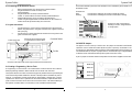
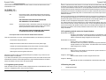
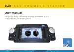
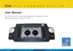
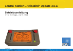
Dynamis ProBox
Dynamis ProBox
3.10 ECoSLink connection
Pro Box User Guide
Dynamis can be connected to an ESU ECoS using a ECoSLink connector (supplied
separately). Please refer to www.dynamisdcc.com for more information
1 Introduction
The icon indicates connection to ECoS.
This document describes how to use the Pro Box to expand the features of the E-Z Command
Dynamis DCC system. It covers how to connect it together, how to use the additional features
and how to add an additional handset (sold separately) to the entire system. Where necessary,
please refer to the E-Z Command Dynamis User Guide.
At the Pro level Dynamis remains an easy-to-use DCC system, however it is very important
that certain procedures are be carried correctly - please read and follow the instructions
carefully.
IR Receiver
IR Extension
3.11 Additional Dynamis Components
Further components in the Dynamis range are available to expand the operation of the system
Handset
item 36-507
Up to a total of 4 handsets may be used so that up to 4
trains are under separate control at once
IR receiver
item 36-509
Up to a total of 5 IR receivers may be connected to the
IR Expander to give IR coverage for a larger layout
www.dynamisdcc.com
Command station
(supplied in 36-505)
Pro Box
The term “Basestation” refers to either the Command Station or the Command Station and Pro
Box combination as appropriate.
2 Making the connections
2.1 Connecting the Pro Box
Printed in China
1
Switch off the handset
2
Power off the Dynamis Command Station
3
Attach the Pro Box to the Command Station by putting them together. The
Command Station fits on the top of the Pro Box. Any BASE ID jumpers to
allow more than one Dynamis system to be used in proximity are fitted to
the pins on top of the Pro Box (section 3.9)
Dynamis ProBox User Guide V02 Jan 09
8
1
Dynamis ProBox
Dynamis ProBox
2.2 Connecting the IR Extension module
1
2
3
4
Remove the IR Receiver from the top of the Command Station
Plug the IR Extension module on the top of the
Command Station
Plug the IR Receiver on the top of the IR Extension
module, or use the cable to connect to remotely located IR Receiver.
Additional IR Receivers can be connected to the IR Extension
module using the supplied cable. The IR Receivers can be mounted in a
location above the layout where they are in clear view.
A locomotive selected by more than one Handset at once is indicated by the ‘Controller’ icon on
the Handset screen.
Controller icon
Solid
Flashing
this Handset is viewing the locomotive controlled by another
this Handset is controlling the locomotive and another is viewing
A viewer can ‘steal’ a locomotive by
activating a function, change direction
or change speed.
2.3 Layout connections
1
2
Connect the Service Track to the track output terminal of the Command
Station using either wires to the green connector block supplied or the lead
with a jack plug
Connect the layout to the output terminal of the Pro Box using wires to the
green connector block supplied
Power supply input
Connect to Service Track with jack
or screw terminal connector block
Command Station
3.9 BASE ID Jumpers
PWR
Track
Pro Box
Track
ECoSLink
The jumpers are set on the top of the Pro Box. Set jumpers as indicated for the BaseID
required to avoid a conflict with another Dynamis system in proximity. All handsets in use
should also have their BaseID setting changed to match the Basestation before powering up.
The default BaseID of 0 requires no jumpers and it is recommended only to change the BaseID
if needed to avoid conflict with another Dynamis system used in the vicinity.
A pair of jumpers is included: standard components from electronics suppliers can be used.
Connect to main track of the layout using screw terminal connector block
BASE ID 0
2.4 Creating a Programming / Service Track
A ‘Programming’ or ‘Service Track’ is an isolated section of track to allow the use of Service
Mode programming methods to write to decoder CVs as well as ‘read’ from them.
The Dynamis Service Track does not need to be physically isolated from the layout although it
must be electrically double isolated from the rest of the layout with an insulated rail joiner in
each rail – for example it could be a track within an engine depot or storage yard. In normal
operations the Service Track is powered from the Command Station output with DCC track
power so that a locomotive can be driven into and out of the section. The internal switching in
the Dynamis unit means that it is not necessary to use an additional external switch.
2
BASE ID 1
BASE ID 2
BASE ID 3
7
Dynamis ProBox
Dynamis ProBox
“Factory Reset” in the “System Menu” of a Handset you will only reset the applicable
Handset. If it is in range of a Pro Box with the same BaseID, it will immediately
resynchronise to this Pro Box.
For example, the siding on this layout is set up to be the
Service Track.
The BaseID and RemoteID of the Handset will both be reset to 0 and may need
to be restored to appropriate values to operate correctly the particular system
in use.
2.
Connect siding to Command Station output
Insulated rail joiners in both rails
to fully separate the Service Track
Global Locomotive Roster reset in Pro Box and Handsets
Reset the locomotive roster of the Pro Box and all attached handsets, write in Service
Mode to CV=7, VALUE=151 using the “Programming Menu” of a Handset. The
BaseID, RemoteID and some other configuration data on the Handset won’t be
changed, but the configuration data of the Pro Box will be reset. Afterwards all
Handsets resynchronise to the Pro Box with a now empty locomotive roster.
MENU -> PROGRAM -> scroll ->PROGRAM ON SERVICE TRACK -> enter CV 7 ->v
VALUE 151 -> PROGRAM
Connect main layout to ProBox output
THE RAIL POLARITY OF THE SECTIONS (LEFT AND
RIGHT HAND RAILS) MUST BE THE SAME OTHERWISE
A SHORT CIRCUIT WILL RESULT WHEN A TRAIN IS RUN
BETWEEN THE TWO SECTIONS
3.6 Change name of Pro Box
3 Operation
MENU ->SYSTEM MENU -> SYSTEM INFO ->EDIT BASE NAME
3.1 Before powering on a Dynamis system, please ensure:
The Pro Box can be given a name of the user’s choice of up to 16 characters.
•
Eg
MY DYNAMIS
•
•
•
3.7 STOP mode behaviour
MENU -> SYSTEM MENU ->EDIT STOPMODE
•
•
The Pro Box jumpers and each handset in use have all been set the same Base ID:
the default is 0 which requires no jumpers and only should be changed if other
Dynamis systems are in operation in the vicinity.
Each Handset to be used has been set to a different Handset ID ( 0 to 3)
Changes should be made before the Basestation is powered up.
Power on the Basestation; then power on Handsets. Take note of the following
comments regarding the choice and synchronisation of roster that is to be used
Power down in reverse order. Handsets first, Pro Box last.
Units must not be switched off during data transmission.
Dynamis can be set to either
cut the power to the track so that all trains stop (recommended for beginners)
Set to POWER OFF
or
send an emergency stop instruction to the locomotive currently under the control of
the Handset. The power is cut from the track if the button is held down.
Set to ESTOP LOCOMOTIVE
3.2 Synchronisation of the locomotive roster
When using the Dynamis Command Station as a standalone unit, the locomotive roster is
handled on the Dynamis Handset. However, when using the Pro Box every unit in the system
(Pro Box and up to 4 Handsets) has a copy of the locomotive roster, which must be
synchronized.
3.8 Viewing, controlling and stealing of locomotives
Synchronization will normally automatically be done in the background and can last up to 1
minute per unit - indicated by the flashing of the yellow LED. The system can be used during
synchronisation with slightly reduced reactivity, but the locomotive roster should not be
modified. Handsets or Basestation must not be switched off during synchronization
When a locomotive or accessory is selected on more than one Handset in a network the screen
displays of all Handsets update to show the same information regarding speed and direction
and current function settings.
When the Pro Box detects a new Handset it has to determine which locomotive roster to use,
either the one the Pro Box already holds or the roster from the newly detected Handset. In
some cases the Pro Box will do this automatically.
6
3
Dynamis ProBox
Dynamis ProBox
If the Pro Box cannot determine which locomotive roster to use the user will be asked on the
Handset which to use:
OK TO RESET INT
LOCOMOTIVE LIST?
OK
the locomotive roster of the handset will be erased and the one
on the Pro Box will be used and automatically synchronized with
the handset.
USE THE ROSTER THAT EXISTS ON THE PRO BOX
AND TRANSFER IT TO THIS HANDSET
Cancel
the locomotive roster of the Pro Box and all other handsets in the
network will be erased and the locomotive roster of this handset
will be synchronized to all other units in the network.
USE THE ROSTER FROM THIS HANDSET AND TRANSFER
TO THE PRO BOX AND ALL OTHER HANDSETS
Do not press cancel on more than one Handset at the same time.
There are cases where you can lose synchronization between your handset and your Pro Box:
- Disconnection during transmission
- Editing the locomotive roster without connection to Pro Box (offline usage)
- Handset disconnected whilst editing the locomotive roster on another Handset
- Connecting the Handset to a different Command Station or Pro Box
- Switching the unit off during data transmission
A Service Track allows the values stored in a locomotive decoder to be determined (‘read’) and
all decoder CVs may have values set (‘written’) by this method. The Dynamis Handset allows a
choice of several methods to write to the CV: those appropriate to the decoder in use should
be determined from decoder instructions and the methods selected following the instructions in
the Dynamis User Guide. Do not attempt to read from more than one decoder at the same time.
During Service Track operation the power is cut from the Main Track, and the output current
threshold is reduced.
During a CV write operation the acknowledgement pulse from the decoder is evaluated and an
error message will be displayed if an error occurs in the write operation. Dynamis does not
abort the write operation which means that decoders without an acknowledge capability can still
be written. An error message will be displayed if faulty a read operation occurs.
The ‘Address Read’ item on the Handset menu is used to determine the address (long or short)
of the locomotive decoder currently on the Service Track . An error message will be displayed
in the event of a faulty read operation. If the Pro Box can successfully read the address from
the decoder, the address of the currently selected locomotive in the roster is changed to the
newly read address.
3.4 Programming methods used on the Dynamis Handset
Write address on Maintrack
Changes a short address to another short address on the Maintrack (If this
supported by the decoder - check with the decoder instructions). The initial
address of the decoder being changed from must be known.
Write address on Servicetrack
Use this option to set an address to a decoder
Overwrites a short or long address on the decoder. Dynamis handles all CV
changes needed to set a long address. The initial address of the decoder
being changed can be unknown.
Read address on Servicetrack
Reads a short or long address from the decoder. Dynamis reads all CV
needed to identify a long address
Merging of locomotive rosters is not possible although it is possible to copy a roster from one
Pro Box to another via a Handset.
Program on Servicetrack
Read and write decoder CV values using the Service Track
If you switch off a Handset or put it out of range from the Pro Box, the Pro Box will remove the
Handset after some time. If the Handset gets back in range it will automatically be connected
back to the network, but it may have to be resynchronised.
Program on Maintrack
Write decoder CV values on the Maintrack to the decoder under control
3.3 Programming track operation
3.5 Resetting the system
When used with a Pro Box, Dynamis can both change decoder CVs on the MainTrack and on a
‘Service’ or ‘Programming’ track, using a second connector.
1.
4
Resetting the handset
5