1
AWS-842TPB/SPB
Industrial Workstation (Version B)
with 10.4" Flat Panel Display
Copyright Notice
This document is copyrighted, June 1998, by Advantech Co., Ltd.
All rights are reserved. Advantech Co., Ltd. reserves the right to
make improvements to the products described in this manual at
any time without notice.
No part of this manual may be reproduced, copied, translated, or
transmitted in any form or by any means without the prior written
permission of Advantech Co., Ltd. Information provided in this
manual is intended to be accurate and reliable. However,
Advantech Co., Ltd. assumes no responsibility for its use; nor for
any infringements of the rights of third parties which may result
from its use.
Acknowledgments
AWS-842TPB, AWS-842TB, AWS-842SPB, AWS-842SB,
AWS-842TPB-T, AWS-842TB-T, AWS-842SPB-T and
AWS-842SB-T are all trademarks of Advantech Co., Ltd. IBM and
PC are trademarks of International Business Machines
Corporation. MS-DOS is a trademark of Microsoft Corporation.
All other brand and product names mentioned herein are
trademarks or registered trademarks of their respective holders.
Part No. 2002084200
1st Edition Printed in Taiwan July l998
ii
FCC Class A
This equipment has been tested and found to comply with the
limits for a Class A digital device, pursuant to Part 15 of the FCC
Rules. These limits are designed to provide reasonable protection
against harmful interference when the equipment is operated in a
commercial environment. This equipment generates, uses and can
radiate radio frequency energy. If not installed and used in
accordance with this user's manual, it may cause harmful
interference to radio communications. Operation of this equipment
in a residential area is likely to cause harmful interference, in
which case the user will be required to correct the interference at
his own expense.
iii
Packing List
Before you set up the AWS-842TPB/SPB, make sure that the
following materials have been included with the package, and that
this manual is in good condition. If anything is missing or
damaged, contact your dealer immediately:
• One AWS-842 Version B industrial workstation with 10.4" flat
panel display and VGA card (PCA-6653)
• One accessory box, including:
- Two power cords (USA type and French type)
- Diskettes for VGA driver
- One utility diskette for function key programming
- AWS-842TPB/SPB User's Manual
- PCA-6653 User's Manual
- Cable to link keyboard to CPU card
- Flat gray cable for 3.5" HDD and slim CD-ROM
- Cable to link external keyboard on backplane to CPU card
- Screw bag with screws
- CD-ROM disc with touchscreen manual and driver (optional)
- Diskettes for touchscreen driver (optional)
• CDR-842-0024 (optional)
The CD-ROM drive for the AWS-842TPB/SPB is packed in a
separate carton, to ensure that it is shipped safely and does not
deteriorate.
- One slim CD-ROM drive
- Screw bag with screws
If any of these items are missing or damaged, contact your
distributor or sales representative immediately.
iv
Additional Information And Assistance
1. Visit the Advantech web sites at www.advantech.com or
www.advantech.com.tw where you can find the latest
information about the product.
2. Contact your distributor, sales representative, or Advantech's
customer service center for technical support if you need
additional assistance. Please have the following information
ready before you call:
• Product name and serial number
• Description of your peripheral attachments
• Description of your software (operating system, version,
application software, etc.)
• A complete description of the problem
• The exact wording of any error messages
v
Safety Instructions
1. Read these safety instructions carefully.
2. Keep this User's Manual for later reference.
3. Disconnect this equipment from any AC outlet before cleaning. Use a damp cloth. Do
not use liquid or spray detergents for cleaning.
4. For plug-in equipment, the power outlet socket must be located near the equipment
and must be easily accessible.
5. Keep this equipment away from humidity.
6. Put this equipment on a reliable surface during installation. Dropping it or letting it
fall may cause damage.
7. The openings on the enclosure are for air convection. Protect the equipment from
overheating. DO NOT COVER THE OPENINGS.
8. Make sure the voltage of the power source is correct before connecting the equipment
to the power outlet.
9. Position the power cord so that people cannot step on it. Do not place anything over
the power cord.
10. All cautions and warnings on the equipment should be noted.
11. If the equipment is not used for a long time, disconnect it from the power source to
avoid damage by transient overvoltage.
12. Never pour any liquid into an opening. This may cause fire or electrical shock.
13. Never open the equipment. For safety reasons, the equipment should be opened only
by qualified service personnel.
14. If one of the following situations arises, get the equipment checked by service
personnel:
a. The power cord or plug is damaged.
b. Liquid has penetrated into the equipment.
c. The equipment has been exposed to moisture.
d. The equipment does not work well, or you cannot get it to work according to the
user's manual.
e. The equipment has been dropped and damaged.
f. The equipment has obvious signs of breakage.
15. DO NOT LEAVE THIS EQUIPMENT IN AN UNCONTROLLED
ENVIRONMENT WHERE THE STORAGE TEMPERATURE IS BELOW
-20° C (-4° F) OR ABOVE 60° C (140° F). THIS MAY DAMAGE THE
EQUIPMENT.
The sound pressure level at the operator's position according to IEC 704-1:1982 is no
more than 70dB(A).
DISCLAIMER: This set of instructions is given according to IEC 704-1. Advantech
disclaims all responsibility for the accuracy of any statements contained herein.
vi
Wichtige Sicherheishinweise
1. Bitte lesen sie Sich diese Hinweise sorgfältig durch.
2. Heben Sie diese Anleitung für den späteren Gebrauch auf.
3. Vor jedem Reinigen ist das Gerät vom Stromnetz zu trennen. Verwenden
Sie Keine Flüssig-oder Aerosolreiniger. Am besten dient ein
angefeuchtetes Tuch zur Reinigung.
4. Die NetzanschluBsteckdose soll nahe dem Gerät angebracht und leicht
zugänglich sein.
5. Das Gerät ist vor Feuchtigkeit zu schützen.
6. Bei der Aufstellung des Gerätes ist auf sicheren Stand zu achten. Ein
Kippen oder Fallen könnte Verletzungen hervorrufen.
7. Die Belüftungsöffnungen dienen zur Luftzirkulation die das Gerät vor
überhitzung schützt. Sorgen Sie dafür, daB diese Öffnungen nicht
abgedeckt werden.
8. Beachten Sie beim. AnschluB an das Stromnetz die AnschluBwerte.
9. Verlegen Sie die NetzanschluBleitung so, daB niemand darüber fallen
kann. Es sollte auch nichts auf der Leitung abgestellt werden.
10. Alle Hinweise und Warnungen die sich am Geräten befinden sind zu
beachten.
11. Wird das Gerät über einen längeren Zeitraum nicht benutzt, sollten Sie es
vom Stromnetz trennen. Somit wird im Falle einer Überspannung eine
Beschädigung vermieden.
12. Durch die Lüftungsöffnungen dürfen niemals Gegenstände oder
Flüssigkeiten in das Gerät gelangen. Dies könnte einen Brand bzw.
elektrischen Schlag auslösen.
13. Öffnen Sie niemals das Gerät. Das Gerät darf aus Gründen der
elektrischen Sicherheit nur von authorisiertem Servicepersonal geöffnet
werden.
14. Wenn folgende Situationen auftreten ist das Gerät vom Stromnetz zu
trennen und von einer qualifizierten Servicestelle zu überprüfen:
a - Netzkabel oder Netzstecker sind beschädigt.
b - Flüssigkeit ist in das Gerät eingedrungen.
c - Das Gerät war Feuchtigkeit ausgesetzt.
d - Wenn das Gerät nicht der Bedienungsanleitung entsprechend
funktioniert oder Sie mit Hilfe dieser Anleitung keine Verbesserung
erzielen.
e - Das Gerät ist gefallen und/oder das Gehäuse ist beschädigt.
f - Wenn das Gerät deutliche Anzeichen eines Defektes aufweist.
Der arbeitsplatzbezogene Schalldruckpegel nach DIN 45 635 Teil 1000 beträgt
70dB(A) oder weiger.
DISCLAIMER: This set of instructions is given according to IEC704-1. Advantech
disclaims all responsibility for the accuracy of any statements contained herein.
vii
Contents
Chapter 1 Introduction .......................................................1
1.1
1.2
1.3
1.4
1.5
1.6
Description ............................................................................... 2
Versatile backplane supply ....................................................... 2
Sealed-membrane tactile-response keypad ............................... 2
Accessible and secure control panel ......................................... 3
Specifications ........................................................................... 4
General ...................................................................................... 4
Touchscreen (optional) ............................................................. 4
Passive backplane ..................................................................... 5
Power supply options ................................................................ 5
LCD display .............................................................................. 6
Dimensions ............................................................................... 7
Complete Functionality .......................................................... 8
Front Accessible CD-ROM .................................................... 9
Front Control Panel .............................................................. 10
Chapter 2 System Setup ..................................................11
2.1
2.2
2.3
2.4
2.5
2.6
viii
General ................................................................................... 12
Opening The Top Panel And Rear Panel............................ 13
Adding Cards ......................................................................... 15
Installing Optional Drives .................................................... 16
Panel Mounting ..................................................................... 20
Rack Mounting ...................................................................... 21
Chapter 3 Macro Key Programming ...............................23
3.1
3.2
3.3
3.4
3.5
Introduction ........................................................................... 24
Macro Components ............................................................... 24
Macro keys .............................................................................. 24
Macro EEPROM ..................................................................... 24
Macro programming utility ..................................................... 24
Syntax ..................................................................................... 25
How To Use SFED842.COM ................................................ 27
Examples ................................................................................ 28
Chapter 4 Maintenance ....................................................31
4.1
4.2
4.3
4.4
4.5
4.6
Detaching The Backplane And Bracket .............................. 32
Power Supply ......................................................................... 33
LCD Maintenance ................................................................. 34
Keyboard Translator ............................................................ 36
LED Board ............................................................................. 39
Touchscreen Controller ........................................................ 39
ix
Appendix A Power Supply Specifications .....................41
A.1
A.2
A.3
260 Watt Power Supply ........................................................ 42
Specifications .......................................................................... 42
General features ...................................................................... 44
Environmental specifications .................................................. 44
International standards compliance ........................................ 45
-48 VDC Power Supply ........................................................... 46
Specifications .......................................................................... 46
Reliability ................................................................................ 49
Environmental specifications .................................................. 49
International standards compliance ........................................ 49
DC output wire list .................................................................. 50
24 VDC Power Supply ............................................................. 51
Specifications .......................................................................... 51
General features ...................................................................... 53
Environmental specifications .................................................. 53
International standards compliance ........................................ 53
Appendix B Touchscreen Driver Installation .................55
B.1
B.2
B.3
B.4
B.5
x
Introduction ........................................................................... 56
Windows 95 ............................................................................ 57
Windows 3.1 and DOS .......................................................... 60
Windows NT .......................................................................... 63
OS/2 (MonitorMouse) ........................................................... 65
CHAPTER
Introduction
• Description
• Specifications
• Dimensions
• Complete functionality
• Front accessible CD-ROM
• Front control panel
1
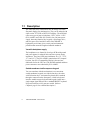
1.1 Description
The AWS-842 series workstations take advantage of modern
flat-panel displays for minimum size. They can be ordered with
either a color TFT LCD or DSTN LCD display. The AWS-842
offers two types of passive backplane, 3 PCI / 4 ISA / 1 CPU
(PCA-6108P3) and 8 ISA (PCA-6108) slots, 260 watt power
supply, data-entry/function-key keypads, a slim floppy drive,
and two spaces for a hard drive and a slim CD-ROM. A
high-quality steel frame gives security and environmental
protection that meets the toughest industrial standards.
Versatile backplane supply
The backplanes were formed by four-layer PCBs with ground
and power planes for reduced noise and lower power-supply
impedence. They have LED power indicators for +5 V, +12 V,
-5 V and -12 V. The PCA-6108P3 contains three PCI-compatible slots, four PC/AT-compatible (ISA-bus) slots and one
dedicated slot for the CPU card. The PICMG standard and three
power connectors were obtained by PCA-6108P3.
Sealed-membrane tactile-response keypad
You can enter data with the workstation’s two convenient
sealed-membrane keypads, one with 60 data keys, the other
with 20 function keys. An external keyboard can be attached
through a connector on the front panel. A built-in keyboard
interface module merges keyboard and keypad signals into a
single output signal that acts like a standard IBM AT keyboard.
No special software or I/O ports are needed. (Refer to
Chapter 4 page 36 for a detailed description.)
2
AWS-842TPB/SPB User's Manual
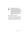
Note:
To use the keyboard and keypad
simultaneously, you must first connect the
keyboard connector on the backplane to the
keyboard connector on the CPU card, and then
connect the external keyboard jack to another
keyboard jack located next to the power supply.
If you connect the keyboard to the 5-pin DIN
connector on the CPU card, neither the
keyboard nor the keypad will work. The
keyboard must be connected to the jack behind
the front door.
Accessible and secure control panel
We have put all the workstation's controls at the front of the
unit for easy access. A door protects the controls from damage.
External controls are: power ON/OFF and reset switches, slim
floppy disk drive, slim CD-ROM drive and external KB port.
Two LEDs indicate power ON and HDD status. There is a
control to adjust the brightness or contrast of the LCD display.
Chapter 1 Introduction
3
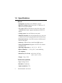
1.2 Specifications
General
• Front panel: Aluminum, meets NEMA 4 or IP 65
• Disk drive housing: Supports one slim 3.5" FDD, one 3.5"
HDD and one slim CD-ROM
• VGA card: CHIPS 65545 ISA-bus card (PCA-6653) with
1 MB DRAM on board, supports simultaneous CRT/LCD
display
• Cooling system: One 49 CFM fan on rear panel
• Membrane keypads: One with 60 data entry keys, one with
10 function keys and 10 programmable macro function keys
• Keyboard connector: 5-pin DIN connector with dust-proof
door on front panel
• Indicators: LEDs for Power On/Off and HDD activity
• Linear VR adjustment: Brightness for TFT LCD, contrast
for DSTN LCD
• Operating temperature: 0 ~ 50° C (32 ~ 122° F)
• Relative humidity: 5 ~ 85% @ 50° C, non-condensing
• CE compliant
• Dimensions (W x H x D): 482 x 266 x 307 mm
(19.0" x 10.5" x 12.1")
• Weight: 15 kg (33 lb)
Touchscreen (optional)
• Type: Analog resistive
• Resolution: Continuous
• Light transmission: 75%
4
AWS-842TPB/SPB User's Manual
• Controller: RS-232 interface
• Power consumption: +5 V @ 200 mA
• Software driver: Supports MS-DOS, Windows 3.1,
Windows 95, Windows NT and OS/2
Passive backplane
• PCA-6108P3: 4 ISA, 3 PCI, 1 CPU slot
• PCA-6108C: 8 ISA slot
Power supply options
AC input 260 W (standard offer)
• Input: 85 ~ 130 VAC or 180 ~ 260 VAC, switchable
• Output:
+5 V @ 25 A; +12 V @ 9 A; -5 V @ 0.5 A; -12 V @ 2.0 A
• MTBF: 100,000 hours
• Safety: UL/CSA/TUV
-48 VDC input 310 W
• Input: -38 ~ -58 VDC
• Output:
+5 V @ 25 A; +12 V @ 10 A; -5 V @ 1 A; -12 V @ 5 A
• MTBF: 100,000 hours
24 VDC input 250 W
• Input: 19 ~ 32 VDC
• Output:
+5 V @ 25 A; +12 V @ 10 A; -5 V @ 1 A; -12 V @ 1 A
• MTBF: 100,000 hours
Chapter 1 Introduction
5
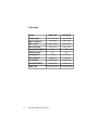
LCD display
Model
AWS-842T
AWS-842S
10.4" TFT color
10.4" DSTN
640 x 480
640 x 480
256 K colors
4096 colors
0.33 x 0.33
0.33 x 0.33
Luminance (cd/m2)
250
130
Viewing angle
90°
90°
Temperature
0 ~ 50° C
0 ~ 45° C
VR controller
Brightness
Contrast
LCD MTBF
50,000 hours
50,000 hours
Backlight MTBF
20,000 hours
25,000 hours
PCA-6653-842T
PCA-6653-842S
Display type
Max. resolution
Max. colors
Dot size (mm)
VGA card
6
AWS-842TPB/SPB User's Manual
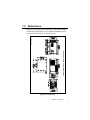
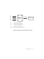
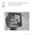
1.3 Dimensions
Cutout dimensions: 445 mm x 240 mm
Unit: mm
Before you rackmount or panelmount the AWS-842TPB/SPB,
use the following diagram to verify that the mounting screws
correspond with the holes in your panel/rack.
Figure 1-1: Dimensions
Chapter 1 Introduction
7
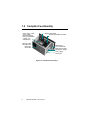
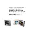
1.4 Complete Functionality
Keyboard translator
4 ISA / 3 PCI / 1 CPU
slot (or 8 ISA)
passive backplane
(Also accommodates
a ``Baby`` AT
motherboard)
VGA card (PCA-6653 included)
Cooling fan with
removable filter
Shielded 10.4``
TFT or CSTN LCD
Heavy-duty
steel frame
Keyboard connector
260 W power supply
Power supply
cooling fan
Figure 1-2: Complete functionality
8
AWS-842TPB/SPB User's Manual
1.5 Front Accessible CD-ROM
Figure 1-3: Front accessible CD-ROM
Chapter 1 Introduction
9
1.6 Front Control Panel
Figure 1-4: Front control panel
10
AWS-842TPB/SPB User's Manual
CHAPTER
2
System Setup
• General
• Opening the top panel and rear panel
• Adding cards
• Installing optional drives
• Panel mounting
• Rack mounting
2.1 General
Your AWS-842TPB/SPB is easy to use. All you have to do is
remove its cover, install your CPU card, display adapter card, an
optional hard disk drive, and whatever additional I/O cards that
your application requires, and you are ready to mount your
workstation into a 19-inch rack or panel.
Warning! Do not begin your installation until you are sure
there is no power flowing within the
AWS-842TPB/SPB. It must be switched off and
unplugged. Every time you access the inside of
the AWS-842TPB/SPB, you should switch it off
and unplug it.
12
AWS-842TPB/SPB User's Manual
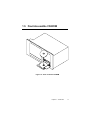
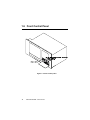
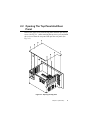
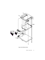
2.2 Opening The Top Panel And Rear
Panel
Remove the eight screws from the top panel and then open the top
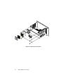
cover. (See Fig. 2-1.) After removing the top cover, you can detach
the six screws from the rear panel and open the rear panel. (See
Fig. 2-2.)
Figure 2-1: Opening the top panel
Chapter 2 System Setup
13
Figure 2-2: Opening the rear panel
14
AWS-842TPB/SPB User's Manual
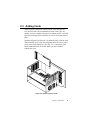
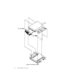
2.3 Adding Cards
The PCI passive backplane accepts both PCI-bus and ISA-bus
CPU and I/O cards. We recommend all-in-one cards. They are
durable, and save valuable slot space by bundling a CPU card with
hard disk and floppy disk controllers, as well as serial and parallel
ports.
Open the top panel (see Section 2.2) and then slowly slide the card
in and carefully press it into the backplane socket. Secure it with a
screw to the top mounting bar. (See Fig. 2-3). Connect the wires.
Install additional cards as needed. When you have finished,
reattach the cover.
Figure 2-3: Installing add-on cards
Chapter 2 System Setup
15
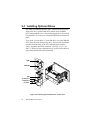
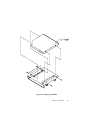
2.4 Installing Optional Drives
The AWS-842TPB/SPB provides space for three drives (one slim
floppy disk drive, one hard disk drive and one slim CD-ROM
drive) underneath the case. A front-facing floppy drive has already
been installed. You can access it from the FDD dust-resistant door
panel.
If you wish, you can add a 3.5" hard disk drive or a slim CD-ROM
drive above the front-facing floppy drive. Unscrew the drivemount
assembly from the body of the case, attach the drive with the
screws, and attach the ribbon connector. (See Figs. 2-4, 2-5, 2-6
and 2-7.) When you have added the drives, set the ribbon cables in
place and mount the drivemount assembly.
HDD
CD-ROM
FDD
To FDD port
To IDE port
To power
Figure 2-4: Installing optional disk drives - overall view
16
AWS-842TPB/SPB User's Manual
Figure 2-5: Installing an FDD
Chapter 2 System Setup
17
Figure 2-6: Installing an HDD
18
AWS-842TPB/SPB User's Manual
Figure 2-7: Installing a CD-ROM
Chapter 2 System Setup
19
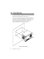
2.5 Panel Mounting
The AWS-842TPB/SPB will stand on a shelf or a table, and it may
be mounted within a panel. Dimensions for the case, the mounting
flange, and the mounting bolts are shown in Fig. 1-1.
Once you have added your cards, drives, and other equipment, you
should switch on the AWS-842TPB/SPB to confirm that it works.
Then set the case within your panel aperture so that your screw
holes line up with the mounting bolts on the flange of the
AWS-842TPB/SPB. Secure the bolts to the panel.
Figure 2-8: Panel mounting
20
AWS-842TPB/SPB User's Manual
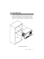
2.6 Rack Mounting
The AWS-842TPB/SPB can also be mounted in a 19" rack. Make
sure that all additional equipment has been installed correctly. Also
make sure that all cabling (such as the monitor signal cable, the
keyboard cable and the monitor power cable) has been reattached.
Attach the rack to the case using screws on both sides of the case.
Figure 2-9: Rack mounting
Chapter 2 System Setup
21
22
AWS-842TPB/SPB User's Manual
CHAPTER
Macro Key
Programming
• Introduction
• Macro components
• Syntax
• How to use SFED842.COM
• Examples
3
3.1 Introduction
Our workstations are equipped with programmable function keys
(macro keys) that greatly enhance the operator interface. Macros,
far more powerful than batch files, automate the most commonly
used input sequences. They extended their functional reach to
within application programs.
3.2 Macro Components
The following article explains how to use and program the
function keys. The complete macro function consists of the
following elements:
Macro keys
Ten programmable macro keys that are located under the monitor
screen of your workstation.
Macro EEPROM
Holds the key sequences that are activated when the corresponding
macro key is pushed.
Macro programming utility
On the disk you will find a program called SFED842.COM. The
SFED software provides an edit function to produce an ASCII file
that contains keystroke sequences for every macro key. After you
have finished editing the file, the program will ask you whether
you want to save the macro script and/or transmit it to the
EEPROM. Macros consist of keystroke sequences to automate the
most common procedures in your application. The way they
function is much like batch files (.BAT) under DOS, but there are
some differences. In a Macro you have to specify the ENTER key
explicitly. Macros give you the possibility to enter key sequences
in an application that was executed by the macro itself.
24
AWS-842TPB/SPB User's Manual
3.3 Syntax
Macro definitions consist of ASCII characters or character codes
for special characters such as ALT, ENTER, SHIFT, F1, SF2, and
so on. These codes are predefined, and SFED842.COM will
display them on the screen for you. They are easily recognizable,
appearing between the square brackets ‘[‘ and ‘]’.
For example :
ALT represents [26]
ENTER represents [33]
In your macro script, you can enter ordinary text (ASCII
characters) or the code(s) of the required special character(s).
For example :
CD\TOOLKIT[33] means CD\TOOLKIT [ENTER]
For combination keystrokes (ALT/SHIFT/CTRL + another key)
enter the codes of the special characters, followed by
[90] (RELEASE).
For example:
ALT-F1 represents [26][44][90]
CRTL-C represents [28]C[90]
SHIFT-B represents [27]B[90]
Chapter 3 Macro Key Programming
25
Please refer to the following examples:
ALT-X represents [26]X[90] or [26]x[90].
ALT-F1 represents [26][44][90]
SHIFT-X represents [27]X[90]
SHIFT-F1 represents [27][44][90]
CTRL-X represents [28]X[90]
CTRL-F represents [28][44][90]
CTRL-ALT-DEL represents [28][26][41][90] (reboot)
CTRL-ALT-A represents [28][26]A[90]
CTRL-SHIFT-1 represents [28][27]1[90]
Another useful function is the DELAY instruction. You can
instruct the macro program to wait before executing the next
keystroke. SFED842.COM displays the codes that you can use for
various delays.
For example:
[86] - Wait for 10 seconds before executing next keystroke
[88] - Wait for 1 minute before executing next keystroke.
[26]A[90][86][26]B[90] means ALT-A, wait 10 seconds, ALT-B
26
AWS-842TPB/SPB User's Manual
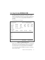
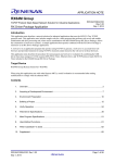
3.4 How To Use SFED842.COM
First, copy all the files to your hard disk and/or make a backup
disk. When starting the macro editor, you will have to specify
either an existing macro script file or a new macro script file. Here
we will create a new file by typing SFED842 NEWKEY.TXT
[ENTER].
The following screen will appear:
Advantech Workstation Special Function Key Edit Program
Rev. 11/16/1995
Table of Control Codes :
Example : SF5 =CD\WINDOWS[33]WIN[33]
TAB [24]
ALT [26]
SHIFT [27]
CTRL [28]
ENTER[33]
PRTSC[7E]
PAUSE[7F]
HOME [3C]
[ [30]
END [3D]
↑ [38]
PGUP [3E]
F1 [44]
PGDN [3F]
F5 [48]
INS [40]
F9 [4C]
DEL [41]
RELEASE [90]
SF1 to SF10 = [70] to [79]
] [31]
↓ [39]
F2 [45]
F6 [49]
F10 [4D]
BS [35]
← [3 A]
F3 [46]
F7 [4A]
F11 [4E]
ESC [36]
→ [3B]
F4 [47]
F8 [4B]
F12 [4F]
Key delay Mode :
0.1 Sec [80]
5 Sec [85]
SF1
SF2
SF3
SF4
SF5
SF6
SF7
SF8
SF9
SF10
0.5 Sec [81]
10 Sec [86]
1 Sec [82]
30 Sec [87]
2 Sec [83]
1 Min [88]
3 Sec [84]
1 Hour [89]
=
=
=
=
=
=
=
=
=
=
KBT ID:AD111695
ESC:Quit/Save/Transmit
Figure 3-1: The Macro Editor screen
When you have finished editing, press the ESC key. At the bottom
line of the screen you will be prompted to choose if you want to
save the file and/or if you want to transmit it to the EEPROM.
After confirmation with the ENTER key, the tasks are carried out
and you return to DOS.
Chapter 3 Macro Key Programming
27
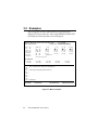
3.5 Examples
We will explain all macro functions that you can find in the
EX842.TXT macro script file. After typing SFED842 EX842.TXT
[ENTER], the following editor screen will appear:
Advantech Workstation Special Function Key Edit Program
Rev. 11/16/1995
Table of Control Codes :
Example : SF5 =CD\WINDOWS[33]WIN[33]
TAB [24]
ALT [26]
SHIFT [27]
CTRL [28]
ENTER[33]
PRTSC[7E]
PAUSE[7F]
[ [30]
HOME [3C]
END [3D]
↑ [38]
PGUP [3E]
F1 [44]
PGDN [3F]
F5 [48]
INS [40]
F9 [4C]
DEL [41]
RELEASE [90]
SF1 to SF10 = [70] to [79]
] [31]
↓ [39]
F2 [45]
F6 [49]
F10 [4D]
BS [35]
← [3 A]
F3 [46]
F7 [4A]
F11 [4E]
ESC[36]
→ [3 B]
F4 [47]
F8 [4B]
F12 [4F]
Key delay Mode :
0.1 Sec [80]
5 Sec [85]
SF1
SF2
SF3
SF4
SF5
SF6
SF7
SF8
SF9
SF10
=
=
=
=
=
=
=
=
=
=
0.5 Sec [81]
10 Sec [86]
1 Sec [82]
30 Sec [87]
2 Sec [83]
1 Min [88]
CD\TOOL[33]SFED842 EXAMPLE.TXT[33]
COPY C:\CONFIG.EMM C:\CONFIG.SYS[33]Y[33][85][79]
C:\WP51\WP[33][86][27][4D][90]REPORT.WP5[33]
[28][26][41][90]
Save(Y/N)?
Transmit(Y/N)?
KBT ID:AD111695
Figure 3-2: Macro examples
28
3 Sec [84]
1 Hour [89]
AWS-842TPB/SPB User's Manual
ESC:Quit/Save/Transmit
SF1 = CD\TOOL[33] SFED842 EXAMPLE.TXT[33]
This macro changes to the TOOL directory, then starts up
SFED842.COM with EXAMPLE.TXT.
SF2 = COPY C:\CONFIG.EMM C:\CONFlG.SYS[33]Y[33][85][79]
The configuration information is changed by copying
CONFIG.EMM to CONFIG.SYS. After a delay of 5 seconds, [85],
the macro, invokes macro function key SF10, [79], which was
defined to reset the system.
SF4 = C:\WP51\WP[33][86][27][4D][90]REPORT.WP5[33]
This example shows that after a macro executes, it is able to direct
the program to accomplish several tasks. WordPerfect is started.
After a delay of 10 seconds (time to load the program), the command Shift-F10, [27][4D], is issued to import a text file. The name
of the text file (REPORT.WP5) is inserted and finally ENTER,
[33], causes the text file to be loaded and appear on the screen.
SF10 = [28][26][41][90]
Restarts the computer (CTRL-ALT-DEL).
Chapter 3 Macro Key Programming
29
30
AWS-842TPB/SPB User's Manual
CHAPTER
4
Maintenance
• Detaching the backplane and bracket
• Power supply
• LCD maintenance
• Keyboard translator
• LED board
• Touchscreen controller
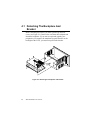
4.1 Detaching The Backplane And
Bracket
Before detaching the bracket, you must open the top and rear
covers (see Figure 2-1). Remove the card from the backplane and
detach the backplane. If you want to repair and upgrade your
peripherals (for example, the membrane keypad controller or the
backlight of the LCD), you must first pull out the bracket.
Figure 4-1: Detaching the backplane and bracket
32
AWS-842TPB/SPB User's Manual
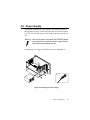
4.2 Power Supply
To repair or upgrade your power supply, first detach and remove
the top and rear covers. Unscrew the four screws on the side panel
(see Fig. 4-2), and disconnect all DC output connectors and the AC
line.
Warning: Shut off all power to the AWS-842TPB/SPB before
you commence to repair the power supply. Switch
off the power and unplug the unit.
For detailed power supply specifications, refer to Appendix A.
Figure 4-2: Installing the power supply
Chapter 4 Maintenance
33
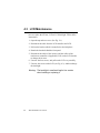
4.3 LCD Maintenance
In the normal working life of the AWS-842TPB/SPB, you may
have to replace the inverter, LCD or LCD backlight. Follow these
instructions:
1. Open the top and rear cover. (See Fig. 2-1.)
2. Disconnect the cable from the LCD controller and LCD.
3. Pull out the bracket which is located below the backplane.
4. Detach the bracket behind the front panel.
5. Disconnect the cables of the inverter, and the cables of the
touchscreen controller (if applicable). Pull out the LCD bracket
to change the inverter.
6. Unscrew the four screws, and pull out the LCD very carefully.
7. Unscrew the screws on the LCD (see Fig. 4-3), and then change
the backlight.
Warning: The backlight is small and fragile. Use caution
when handling or replacing it.
34
AWS-842TPB/SPB User's Manual
Figure 4-3: Installing the LCD backlight
Chapter 4 Maintenance
35
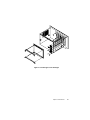
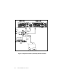
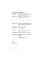
4.4 Keyboard Translator
The keyboard translator is an interface which switches the signal
from the membrane keypad to the standard AT keyboard. There
are six connectors on the board. On top of the board, there are two
connectors linking two flat cables with the larger membrane
keypad (as shown in Fig. 4-5). On the side of the board, there are
four connectors. For connection details, refer to Fig. 4-5.
When servicing the keyboard translator:
1. Switch off the power, and detach the main power cord.
2. Detach the work drawer and cover from the AWS-842TPB/SPB
unit. (See Fig. 2-1.)
3. Pull out the work drawer out as far as it will go.
4. Remove the keypad connector protective bracket.
5. Carefully detach all cables connected to the keyboard
translator. (See Fig. 4-5.)
6. Unscrew the four screws on the corners, pull out the keyboard
translator, and replace it.
36
AWS-842TPB/SPB User's Manual
(A)
(B)
(F)
Keyboard
translator
(C) to (C')
CPU card
(O)
(A)
Input from external keyboard (A)
(B)
Input from external keyboard (B)
(F)
Input from function keypad (F1, F2, ...)
(O)
Input from operation keypad (1, 2, 3, ...)
(C) to (C')
Output to CPU card's keyboard connector
Figure 4-4: Keyboard translator input/output (basic schematic)
Chapter 4 Maintenance
37
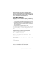
Figure 4-5: Keyboard translator input/output (detailed schematic)
38
AWS-842TPB/SPB User's Manual
4.5 LED Board
It is very unlikely that the LED board will have to be replaced.
There are two indicators in the LED board: HDD and power. You
do not need to remove the backplane and bracket to replace the
LED board. Simply detach the bays for the FDD, HDD and slim
CD-ROM drive, and then unscrew the three screws fixed into the
panel. Before removing the LED board, carefully detach the cables
by pulling them down.
4.6 Touchscreen Controller
To service or replace the touchscreen controller:
1. Open the top and rear cover. (See Fig. 2-1.)
2. Disconnect the cable from the LCD controller and LCD.
3. Pull out the bracket which is located below the backplane.
4. Detach the bracket behind the front panel.
5. Disconnect the cables of the inverter, and the cables of the
touchscreen controller.
6. Replace the touchscreen controller.
Caution: Do not bend the touchscreen tail which is attached
to the touchscreen sensor.
Chapter 4 Maintenance
39
40
AWS-842TPB/SPB User's Manual
APPENDIX
Power Supply
Specifications
• 260 watt power supply
• -48 VDC power supply
• 24 VDC power supply
A
A.1 260 Watt Power Supply
The AWS-842TPB/SPB off-line switching power supply is ideal
for use in workstations. It has been designed to meet UL, CSA and
TUV safety standards. It has been tested and found to comply with
the limits for a Class B digital device, pursuant to Part 15 of the
FCC Rules. These limits are designed to provide reasonable
protection against harmful interference when the equipment is
operated in a commercial environment.
Specifications
Input voltage:
85 ~ 130 VAC and 180 ~ 260 VAC
Input frequency:
47 ~ 63 Hz
Inrush current:
Not exceeding 35 A @ 115 VAC or 70 A @
230 VAC ; cold start @ 25° C
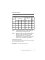
Output load range:
Table A-1: 260 watt power supply output load range
Output
No.
1
Output
+5 V
Min.
load
1.0 A
Rated
load
25 A
Peak
load
28 A
Voltage
accuracy
4.90 ~ 5.10 V
2
+12 V
0.1 A
9A
10 A
11.28 ~ 12.72 V
3
-12 V
0A
2.0 A
-
-11.40 ~ -12.60 V
4
-5 V
0A
0.5 A
-
-4.75 ~ -5.25 V
At the factory, the +12 V output was set at 40% of its rated load,
and other outputs were set at 60% of their respective rated loads.
The +5 V output was set between 5.00 and 5.10 V. The other
outputs were confirmed to be within their respective voltage
accuracy ranges.
42
AWS-842TPB/SPB User’s Manual
Output power:
Total DC continuous power does not exceed 260 W. Total DC
peak power does not exceed 280 W. When the input voltage is less
than 100 VAC, total DC continuous power should not exceed 220 W.
Ripple and noise:
Peak to peak ripple and noise for +12 V is less than 140 mV. Peak
to peak ripple and noise for other outputs is less than 1% of each
output’s respective voltage at the rated load (namely 115/230 VAC).
Measurements were performed with a 15 MHz bandwidth limited
oscilloscope, and each output was terminated with a 0.47 µF
capacitor.
Line regulation:
The output line regulation for +12 V is less than ±2%. The output
line regulation for other outputs is less than ±1%, when measured
at each output’s respective rated load and under ±10% changing
input voltage conditions.
Load regulation:
The values for each of the following output numbers were obtained
by changing each output load ±40% from the 60% rated load,
whilst simultaneously keeping all other outputs at 60% of their
respective rated loads.
Table A-2: 260 watt power supply load regulation
Output No.
1
Load regulation
±3%
2
±5%
3
±1%
4
±1%
Appendix A Power Supply Specifications
43
Hold up time:
14 ms typical @ 115 VAC
This figure was obtained from the last AC line charging pulse to
the point where +5 V dropped down to +4.75 V.
Power good signal:
When the power is turned on, the power good signal will activate
100 to 500 ms after all output DC voltages are operating within
thier respective regulation limits.
Power fail signal:
This will activate at least 0.5 ms before any of the output voltages
fall below their respective regulation limits.
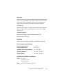
General features
Output protection:
If for some reason the power supply fails to control itself, the
built-in over-voltage protection circuit will shut down the outputs
to prevent damage to external circuits. The trip point of the
crowbar circuit is approximately 5.9 ~ 7.0 V. The power supply
will go into hiccup mode under short circuit or overload
conditions, and will recover automatically when such conditions
cease to exist.
Environmental specifications
Operating temperature: 0 ~ 50° C, input 104/244 V
Storage temperature:
44
-40 ~ 75° C
AWS-842TPB/SPB User’s Manual
International standards compliance
Safety: UL 1950, CSA 22.2 No. 234, TUV EN 60950
EMI:
Conductivity: FCC Docket 20780 (Curve B)
VCCI II, CISPR 22 Level B
Radiation:
FCC Docket 20780 (Curve B)
VCCI I, CISPR 22 Level A
EMS:
IEC-801-2:
IEC-801-3:
IEC-801-4:
Lifetime:
8 KV (air discharge), Criteria B
10 V/M unmodulated, Criteria A
2 KV, Criteria B
More than 3 years @ 70% load @ 25° C
Appendix A Power Supply Specifications
45
A.2 -48 VDC Power Supply
The following specifications describe the physical and electrical
characteristics of a 310 W, four output, DC to DC switching power
supply housed in a standard size PS/2 casing.
Specifications
46
Input voltage:
-38 ~ -58 VDC (continuous operation)
-48 VDC (normal operation)
Input current:
10 A max. @ -48 VDC input
Inrush current:
5 A max. @ -48 VDC input
Efficiency:
70% min. @ full load and normal line
voltage
AWS-842TPB/SPB User’s Manual
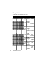
Output characteristics:
Table A-3: -48 VDC power supply output characteristics
Total regulation
tolerance
Loading current
Output
voltage
Noise
plus
ripple
Min.
Max.
Surge
Max.
Min.
Max.
+5 VDC
2A
25 A
30 A
+3%
-3%
50 mV
p-p
+12 VDC
0A
10 A
12 A
+3%
-3%
120 mV
p-p
-5 V DC
0.0 A
1.0 A
-
+5%
-5%
50 mV
p-p
-12 V DC
0.0 A
5A
-
+3%
-3%
120 mV
p-p
Note 1:
Total regulation tolerance includes temperature
change, warmup drift and dynamic load.
Note 2:
Ripple and noise were measured differentially at
the power supply using loads that were each
shunted by at least a 0.1 µF ceramic disc
capacitor and a 10 µF electrolytic capacitor, each
capacitor having a bandwidth up to 20 MHz.
Overshoot (resistive load):
Any output overshoot when the power is turned on does not exceed
10% of the nominal output voltage.
Output power: Maximum continuous: 310 W
Appendix A Power Supply Specifications
47
Power good and power fail signals (optional):
When the power is turned on, the power good signal will activate
100 to 500 ms after all output DC voltages are operating within
their respective regulation limits.
The power fail signal will activate at least 1 ms before the +5 V
output voltage falls below its regulation limit.
Short circuit protection:
A short circuit placed on any output to ground is shut down. When
the short circuit conditions have ceased to exist, power will then be
recycled to restart the power supply.
Over-current protection:
The power supply will shut down all the DC outputs when any
output is overloaded beyond its current limit or beyond its nominal
line voltage limit. When the over-current conditions have ceased to
exist, power will then be recycled to restart the power supply.
Current limit ranges:
5 V:
12 V:
-12 V:
-5 V:
32 ~ 45 A
13 ~ 20 A
6 ~ 12 A
1.5 ~ 3 A
Over-voltage protection:
The power supply will shut down all the DC outputs when any
output maximum voltage limit is exceeded. When the over-voltage
conditions have ceased to exist, power will then be recycled to
restart the power supply.
Voltage limit ranges:
48
5 V:
6.25 ±0.75 V
12 V: 14 ±1 V
-5 V: -6.25 ±0.75 V
-12 V: -14 ±1 V
AWS-842TPB/SPB User’s Manual
Reset time:
When the power supply has automatically shut down, and the short
circuit, over-current and/or over-voltage conditions have ceased to
exist, power will be automatically recycled to restart the power
supply within 3 seconds of such return to normal conditions.
No load start:
When the power supply is switched on but with no load connected,
the power supply does not get damaged, and it is still completely
safe for users.
Transient response:
Dynamic load change: ±50% of maximum rating load
Recovery time: 500 µs max.
Reliability
Mean time between failures (MTBF): 100,000 hours minimum
Environmental specifications
Operating temperature:
0 ~ 50° C
Storage temperature:
-40 ~ 60° C
Operating and storage humidity:
10 ~ 95% RH
Operating altitude:
sea level ~ 15,000 ft
Storage altitude:
sea level ~ 50,000 ft
International standards compliance
Safety: UL 1950
CSA 22.2 No. 234
TUV EN 60950
EMI:
FCC Part 15 Subpart J Class B
Appendix A Power Supply Specifications
49
DC output wire list
All DC output cables use UL 1007 type wires.
Table A-4: -48 V DC power supply DC output wire list
Connector Output Color
50
Wire Length
#AWG (mm)
P8-1
PG
Orange
18
P8-2
P8-3
+5 V
+12 V
Red
Yellow
18
18
P8-4
-12 V
Blue
18
P8-5
P8-6
COM
Black
18
COM
Black
18
P9-1
COM
Black
18
P9-2
COM
Black
18
P9-3
-5 V
White
18
P9-4
P9-5
+5 V
Red
18
+5 V
Red
18
P9-6
+5 V
Red
18
PE-1
+12 V
Yellow
18
PE-2
PE-3
COM
COM
Black
Black
18
18
PE-4
+5 V
Red
18
PF-1
+5 V
Red
20
PF-2
COM
Black
20
PF-3
PF-4
COM
+12 V
Black
Yellow
20
20
PA-1
+12 V
Yellow
18
PA-2
COM
Black
18
PA-3
COM
Black
18
PA-4
+5 V
Red
18
PB-1
+12 V
Yellow
18
PB-2
COM
Black
18
PB-3
COM
Black
18
PB-4
+5 V
Red
18
AWS-842TPB/SPB User’s Manual
Housing
Terminal
BURNDY
BURNDY
300
GTC 6P-1
DCK 18-2TR9
+30/-10
or
or equivalent
equivalent
BURNDY
BURNDY
300
GTC 6P-1
DCK 18-2TR9
+30/-10
or
or equivalent
equivalent
AMP
300
480424-0
+30/-10
or
equivalent
AMP
61314
or equivalent
AMP
150
171822-4
+30/-10
or
equivalent
AMP
170262-1 or
equivalent
AMP
300
480424-0
+30/-10
or
equivalent
AMP
61314
or equivalent
AMP
150
480424-0
+30/-10
or
equivalent
AMP
61314
or equivalent
A.3 24 VDC Power Supply
This is a DC to DC switching mode power supply with a 24 VDC
input.
Specifications
Input voltage:
+19 ~ +32 VDC (normal operation)
Input current:
16 A max. @ +24 VDC input
Inrush current:
10 A max. @ +24 VDC input
Output load range:
Table A-5: 24 VDC power supply output load range
Output
No.
1
Output
+5 V
Min.
load
1.0 A
Rated
load
25 A
Peak
load
30 A
Voltage
accuracy
4.90 ~ 5.10 V
2
+12 V
0A
10 A
12 A
11.28 ~ 12.72 V
3
-12 V
0A
1A
2A
-11.40 ~ -12.60 V
4
-5 V
0A
1A
2A
-4.75 ~ -5.25 V
At the factory, the +5 V output was set between 5.00 and 5.10 V,
while other outputs were simultaneously set at 60% of their
respective rated loads.
The -5 V and -12 V outputs can be used at their respective rated
loads. The +5 V output should carry a load of at least 4 A.
Output power:
Total DC continuous power does not exceed 250 W. Each output
should be able to operate continuously under its maximum load.
Ripple and noise:
Peak to peak ripple and noise for each output is less than 1% of
each output’s respective voltage. Measurements were performed
with a 15 MHz bandwidth limited oscilloscope, and each output
was terminated with a 0.47 µF capacitor.
Appendix A Power Supply Specifications
51
Line regulation:
The output line regulation for each output is less than ±1%, when
measured at each output’s respective rated load and under ±10%
changing input voltage conditions.
Load regulation:
The values for each of the following output numbers were obtained
by changing each output load ±40% from the 60% rated load,
whilst simultaneously keeping all other outputs at 60% of their
respective rated loads.
Table A-6: 24 VDC power supply load regulation
Output No.
1
Load regulation
±4%
2
±5%
3
±3%
4
±3%
Power good signal:
When the power is turned on, the power good signal will activate
100 to 500 ms after all output DC voltages are operating within
their respective regulation limits.
Power fail signal:
This will activate at least 0.5 ms before any of the output voltages
fall below their respective regulation limits.
52
AWS-842TPB/SPB User’s Manual
General features
Efficiency:
65% typical when measured at nominal input and rated load.
Input protection:
Protection against wrong polarity if the +24 V input voltage is
mistakenly reversed.
Output protection:
If for some reason the power supply fails to control itself, the
built-in over-voltage protection circuit will shut down the outputs
to prevent damage to external circuits. The trip point of the
crowbar circuit is approximately 5.7 ~ 7.0 V. The power supply
will go into hiccup mode under short circuit or overload
conditions, and will recover automatically when such conditions
cease to exist.
Environmental specifications
Operating temperature: 0 ~ 45° C
Storage temperature:
-40 ~ 75° C
International standards compliance
Safety: UL 1950 D3
CSA 234
TUV EN 60950
Appendix A Power Supply Specifications
53
54
AWS-842TPB/SPB User’s Manual
APPENDIX
Touchscreen Driver
Installation
• Introduction
• Windows 95
• Windows 3.1 and DOS
• Windows NT
• OS/2 (MonitorMouse)
B
B.1
Introduction
Before you attempt installation of the touchscreen driver, you should
carefully read the instructions in the relevant "read me" file stored in
the installation CD-ROM. The file path for the instructions in the
CD-ROM is:
D:\monmouse\
This is where you will find instructions for Win 95, DOS 3.1, Win
NT, and OS/2.
56
Note 1:
The touchscreen driver must be installed from the
CD-ROM supplied. The CD-ROM drive is designated
as "D" throughout this chapter.
Note 2:
The installation instructions assume that the
touchscreen is connected to COM1, and that the
mouse is connected to and set for COM2. Both of
these configurations are factory pre-settings.
Note 3:
The following illustrations of windows are examples
only. You must follow this manual's flowchart
instructions, and pay attention to the instructions
which then appear on your screen.
AWS-842TPB/SPB User's Manual
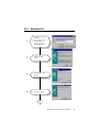
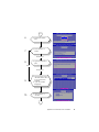
B.2
Windows 95
1.
a. Insert the ELO driver
CD disc.
b. Select "Start", "Run".
c. Type the path
eg. "d:\monmouse\
win95\setup.exe".
2.
a. Press the "Next"
button.
3.
a. Set the path of the
directory.
4.
a. Choose "Typical".
Appendix B Touchscreen Driver Installation
57
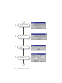
5.
a. Click "OK" to upgrade
the driver.
6.
a. Click "OK" to make a
backup copy.
7.
a. Click "OK" to start the
wizard.
8.
a. Click "OK" to accept
the default.
58
AWS-842TPB/SPB User's Manual
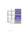
9.
a. Click "OK" but do not
reboot.
10.
a. Exit and reboot.
b. Select "Start",
"Settings", "Control
Panel".
c. Double click "Elo
touchscreen".
11.
a. Click "Calibrate".
END
Appendix B Touchscreen Driver Installation
59
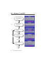
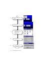
B.3
Windows 3.1 and DOS
1.
a. Execute "install.exe" in
the DOS environment.
b. Press <Enter> to
continue.
2.
a. Type the installing
path of the ELO
directory.
3.
a. Select "Dos.." or
"Windows..".
Windows 3.1
a. Follow the on-screen
instructions.
4.
DOS
Windows 3.1
5.
60
a. Choose the "Serial"
item.
AWS-842TPB/SPB User's Manual
6.
COM1
COM2
COM3
COM4
a. Select the "COM1"
item.
COM2
COM3
COM4
a. Press <Enter> to
install.
7.
Windows 3.1
a. Type the Windows 3.1
path.
8.
DOS
Windows 3.1
9.
10.
a. Add "nomouse.com" to
"autoexec.bat" if there
is no mouse driver
installed.
b. If yes, the window
disappears.
a. Press <Enter> to
continue.
Appendix B Touchscreen Driver Installation
61
11.
a. Choose "Overwrite...".
Windows 3.1
a. Press <Enter> to
continue.
12.
DOS
13.
Windows 3.1
a. Choose "Overwrite...".
Windows 3.1
14.
a. Type "go" to run
calibration.
b. Touch fix points to
calibrate.
END
62
AWS-842TPB/SPB User's Manual
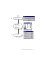
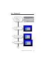
B.4
Windows NT
1.
a. Insert the ELO driver
CD disc.
b. Select "Start", "Run".
c. Type the path.
eg. "d:\monmouse\
winnt\setup.exe".
2.
a. Press the "Next"
button.
3.
a. Set the directory path.
4.
a. Choose "Typical".
Appendix B Touchscreen Driver Installation
63
5.
a. Press "OK" to accept the
default.
6.
a. Click "OK".
7.
a. Exit and reboot.
b. Select "Start", "Settings",
"Control Panel".
c. Double click "Elo
touchscreen".
8.
a. Click "Calibrate".
9.
a. Test the calibration.
END
64
AWS-842TPB/SPB User's Manual
B.5
OS/2 (MonitorMouse)
First, be sure OS/2 is installed and operating properly with your
mouse. We suggest that you prepare OS/2 installation disks or a
bootable DOS disk. By doing so, you can easily reboot from such
disks should an improper setting in CONFIG.SYS cause the system to
not work.
Five steps are required when installing MonitorMouse for OS/2:
Step 1 - Configure your Controller
Step 2 - Copy the Software
Step 3 - Modify CONFIG.SYS
Step 4 - Install the Touchscreen Control Panel
Step 5 - Calibrate the Touchscreen
STEP 1 - CONFIGURE YOUR CONTROLLER
Verify your controller configuration. Elo typically ships touchscreen
controllers preconfigured for use with Elo software, including
MonitorMouse for OS/2. Configuration requires setting switches
and/or installing jumpers that determine controller operating
parameters. You will need these parameters when you install the
MonitorMouse for OS/2 driver software. For controller installation
instructions, refer to the IntelliTouch Product Manual or the
AccuTouch Product Manual.
Appendix B Touchscreen Driver Installation
65
STEP 2 - COPY THE SOFTWARE
The following files are on the MonitorMouse for OS/2 disk:
!READ.ME!
Text file containing any additions or changes
made after this manual was printed.
MONMOU01.SYS Touchscreen driver for serial touchscreen
controllers on PC bus systems.
MONMOU02.SYS Touchscreen driver for serial touchscreen
controllers on Micro Channel systems.
MONMOU03.SYS Touchscreen driver for PC bus and Micro
Channel touchscreen controllers.
ELOCAL2.EXE
Touchscreen control panel software program
used to calibrate the touchscreen and to select
options.
ELOCAL2.DLL
Used by ELOCAL2.EXE.
ELOCAL2.HLP
Help file for ELOCAL.EXE.
ELO.BMP
Elo desktop wallpaper.
@6253.ADF
Description file for the E271-2202 Micro
Channel touchscreen controller.
COMDUMP.EXE
DOS program for testing serial touchscreen
controllers.
BUSSTAT.EXE
DOS program for testing PC bus touchscreen
controllers.
SAWDUMP.EXE
DOS program for testing IntelliTouch
touchscreen controllers.
Create a subdirectory on your hard disk and copy the files into it. For
example:
CD \
MD ELO
COPY A:*.* ELO
66
AWS-842TPB/SPB User's Manual
International versions of the touchscreen control panel software
program are included in subdirectories on the MonitorMouse for OS/2
disk. Replace ELOCAL2.DLL and ELOCAL2.HLP on your hard disk
with the versions from the appropriate subdirectory.
STEP 3 - MODIFY CONFIG.SYS
MonitorMouse for OS/2 is installed by commands in CONFIG.SYS.
Use your system editor to make these changes. In general, the changes
are as follows:
1. Comment-out the existing DEVICE command(s) for your mouse.
2. Add a DEVICE command for the appropriate MonitorMouse for
the OS/2 touchscreen driver immediately after the commented-out
DEVICE commands(s).
3. Add a new DEVICE command for MOUSE.SYS.
The order of the DEVICE commands is important. Other changes may
be required depending on your hardware configuration and version of
OS/2.
Serial Touchscreen Controller on PC Bus System
Change your CONFIG.SYS file as follows:
Rem C:/OS2\MOUSE.SYS {Flags}
Device=c:\elo\monmou01.sys <controller>, <COM
port>,<baud rate>
Device=c:\os2\mouse.sys stype=elomou$ {Flags - keep
same as above}
Where:
<controller> is:
2300 for the IntelliTouch E281-2300 serial controller.
4002 for the IntelliTouch E281{A}-4002 serial controller.
2210 for the AccuTouch E271-2210 serial controller.
140 for the AccuTouch E271-140 serial controller.
Appendix B Touchscreen Driver Installation
67
<COM port> is:
the number of the COM port where the serial output of the
touchscreen controller is connected.
<baud rate>
matches the switch or jumper settings on the controller.
Example MonitorMouse for OS/2 DEVICE command:
Device=c:\elo\monmou01.sys 2210,1,9600
No Mouse
If you do not wish to have a mouse connected, change the
“stype=elomou$” flag to “type=elomou$” on the
DEVICE=MOUSE.SYS command.
Disabling the COM Drivers
If your system COM ports are being used by the touchscreen and
mouse, REM out the DEVICE=COM.SYS and DEVICE=VCOM.SYS
commands (if present) in CONFIG.SYS. This prevents the COM
drivers from displaying amessage saying the COM port is unavailable.
If only the touchscreen is using a COM port, move the
DEVICE=COM.SYS and DEVICE=VCOM.SYS commands before
the DEVICE=MONMOU02.SYS command in CONFIG.SYS. Then
add the flag (<COM Port>,0,0) to COM.SYS, where <COM Port> is
the same as on the DEVICE=MONMOU01.SYS command. For
example:
Device=c:\os2\com.sys (1,0,0)
68
AWS-842TPB/SPB User's Manual
STEP 4 - INSTALL THE TOUCHSCREEN CONTROL PANEL
The touchscreen control panel software program, ELOCAL2.EXE, is
a presentation manager application for calibrating the touchscreen and
setting various options.
Add the \ELO\ELOCAL2.EXE program to the System Setup folder
and label the icon “Touchscreen”. This is accomplished as follows:
1. Open the OS/2 System folder, then System Setup.
2. Open the Templates folder.
3. Drag the Program template with the right mouse button into the
System Setup folder. A Settings notebook will be displayed.
4. Enter “C:\ELO\ELOCAL2.EXE” as the path and file name. Enter
“C:\ELO” as the working directory.
5. Select the "General" tab. Change the Title to “Touchscreen”.
6. Close the notebook.
See your OS/2 documentation for detailed instructions on installing
new applications.
STEP 5 - CALIBRATE THE TOUCHSCREEN
Double-click the Touchscreen icon with the mouse (as the
touchscreen may not be calibrated yet), or use the keyboard if the
mouse is not connected. You may also run ELOCAL2.EXE from an
OS/2 Window prompt.
Select "Calibrate" and follow the on-screen instructions. After
calibrating, the touchscreen will work like the mouse. The
DEVICE=MONMOUxx command in CONFIG.SYS is updated with
the new calibration points (-c flag). The calibration points are then set
automatically each time the system is started. Recalibration should
only be necessary after moving or resizing the video image, or after
changing either the touchscreen, controller, or monitor.
Close the touchscreen control panel.
Appendix B Touchscreen Driver Installation
69
70
AWS-842TPB/SPB User's Manual