1
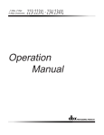
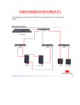
dB10
Owner’s
Manual
PASSIVE DIRECT BOX
®
8760 South Sandy Parkway • Sandy, Utah 84070
Phone: (801) 568-7660 • Fax (801) 568-7662
Int’l Fax: (801) 568-7583
E-mail us at: [email protected]
or visit us on the web at: www.dbxpro.com
Printed 3/2008
dB10 Owner’s Manual 18-XXXX-A
©2008 Harman International Industries, Incorporated, all rights reserved.
18-0555-A
DECLARATION OF CONFORMITY
For your protection, please read the following:
Important Safety Instructions
declares that the product:
Product name:
Product option:
1.
2.
3.
4.
5.
6.
dB10
None
conforms to the following Product Specifications:
Safety
EMC
IEC 60065 (7th ed. 2001) Not
applicable, SELV Device
EN 55013 (2001+A1)
7.
Not applicable, all passive components
EN 55020 (1998)
Not applicable, all passive components
8.
Supplementary Information:
The product herewith complies with the requirements of
the Low Voltage Directive 73/23/EEC and the EMC Directive
89/336/EEC as amended by Directive 93/68/EEC.
Director of Engineering - dbx 8760 S. Sandy Parkway
Sandy, Utah 84070, U.S.A.
Date: February 21, 2008
European
Contact:
Your local dbx Sales and Service Office or
Harman Music Group
8760 South Sandy Parkway
Sandy, Utah, 84070 U.S.A.
Ph: (801) 566-8800
Fax: (801) 568-7583
Introduction
Warning
Manufacturer’s Name: dbx Professional Products
Manufacturer’s Address: 8760 S. Sandy Parkway
Sandy, Utah 84070, U.S.A.
9.
10.
11.
12.
Read these instructions.
Keep these instructions.
Heed all warnings.
Do not use this apparatus near water.
Clean only with dry cloth.
Do not block any ventilation openings. Install in accordance with the manufacturer’s instructions.
Do not install near any heat sources such as radiators,
heat registers, stoves, or other apparatus (including
amplifiers) that produce heat.
Protect the power cord from being walked on or
pinched particularly at plugs, convenience receptacles,
and the point where they exit from the apparatus.
Unplug this apparatus during lightning storms or when
unused for long periods of time.
No user serviceable parts inside. Refer all servicing to
qualified service personnel. Servicing is required when
the apparatus has been damaged in any way, such as
power-supply cord or plug is damaged, liquid has been
spilled or objects have fallen into the apparatus, the
apparatus has been exposed to rain or moisture, does
not operate normally, or has been dropped.
WARNING: To reduce the risk of fire or electric shock,
do not expose this apparatus to rain or moisture.
Refer to labels on the unit, including bottom cover, or
other markings and pertinent information.
Congratulations on your purchase of the dB10 Passive Direct Box. The dB10 offers all
the benefits of a premium-quality Direct Box while preserving the sonic integrity and
true characteristics of the signal source with its custom dbx mu-metal-shielded audio
transformer, and high-quality Neutrik® connectors. The dB10 includes a pad switch for
instrument, line and even speaker level signals. And you can even take more control of
your sound by utilizing the polarity invert switch to set the phase relationship between
the direct and mic’d sound.
The dB10 Features
•
•
•
•
•
•
•
•
•
Premium Performance
Rugged Design
Stackable Chassis with
Durable Rubber Foot
Gold-plated Neutrik® XLR Connector
Premium Chrome Toggle Switches
Hi-Z ¼" Input Jack
Parallel ¼" Thru Jack
Transformer Isolated
Premium Shielded Custom dbx Transformer
•
•
•
•
•
Balanced XLR Lo-Z Output
3-Way 0/20/40 dB Pad Switch
Flat/High-Cut Filter Switch
Output Polarity Invert Switch
Ground Lift Switch
Front Panel
Front Panel
INPUT
THRU
PAD
0dB
20dB
40dB
1 2
1.
INPUT
Connect your signal source to this 1/4” unbalanced TS connector.
2.
PAD
Select a 0dB, 20dB, or 40dB pad with this switch. Allows connection to a wide range of
input signal levels.
3.
THRU
Connect your onstage amplifier here (optional). This 1/4” unbalanced TS connector is directly
connected to the Input jack.
3
Rear Panel
Rear Panel
1.
PIN 1 (LIFT/GND)
By switching to the LIFT position, the internal connection to the output pin 1 is removed,
isolating the dB10’s grounding system from the rest of the system. This eliminates many
“hum” or “buzz” problems due to ground loops.
2.
OUTPUT
Connect this balanced XLR connector to an XLR input on your mixer.
3.
POLARITY (INVERT/NORMAL)
When in the INVERT position, this switch swaps pin 2 and pin 3 of the XLR jack, making pin
3 hot.
4.
FILTER (
/ FLAT)
When in the “
” (filter) position (and the PAD switch is set to 40 dB), this switch applies
a high cut filter to roll off high frequencies (commonly used in conjunction with the 40 dB
pad on an amplifier output signal to roughly duplicate the sound of a mic’d speaker).
OUTPUT
POLARITY FILTER
PIN 1
LIFT
INVERT
GND
NORMAL
1
2
FLAT
3 4
What Does a Direct Box Do?
Example Setup 1: Guitar signal sent to amp and PA/Mixer
First, a direct box converts the audio signal originating from an unbalanced device (like a guitar)
to a balanced audio signal for transmission over a longer distance than is recommended for an
unbalanced signal to travel. As audio industry people know, the advantage of a balanced signal
is realized at the receiving end (audio input) of the balanced cable, typically in the form of a
mic pre-amp input on a mixing console. The mic pre input circuitry consists of a “differential
amplifier” whose job it is to “accept” the audio portion of input signal and “reject” the noise
portion of the signal. The noise portion happens to be roughly equivalent on (or “common to”)
both the “+” and “-” balanced conductors in the mic cable, since external electromagnetic fields
are induced onto both conductors in a roughly similar fashion. Since the conductors are always
in a “twisted pair” configuration, they “see” the same noise field. Thus, this is known as “common-mode noise”. Another type of common-mode noise somewhat evenly-induced onto both
conductors is due to the inherent physics of connecting two pieces of equipment together and the
resulting flow of electrons due to noise voltages present at each piece of equipment. The ability
of a balanced input to reject common-mode noise is measured in dB and called its “common-mode
rejection ratio”, or CMRR.
4
6
4
2
0
6
4
6
4
0
0 +1
Mute
Mute
L/R
L/R
+5
0
0
-5
-5
Pan
Mute
L/R
0
-5
-10
-10
-10
-10
-10
-20
-20
-20
-20
-20
-30
-
-30
-
-30
-
-30
-
3
-30
-
4
-30
-
5
+5
+5
-10
-20
2
Pan
+10
-10
-20
-30
-
+2
+3
-10
1
0 +1
+4
-5
+5
-20
-30
-
Aux 2 10
-1
-2
+3 -3
+10
+5
0
-5
8
0
+2
+4 -4
-5
+5
Mute
L/R
+10
+5
0
-5
6
8 2
0 +1
-2
+3 -3
Mute
+10
+5
0
-5
Aux 1 10
4
Aux 2 10
-1
+2
Pan
6
8
0
6
+4 -4
-5
+5
0
0 +1
-2
+3 -3
L/R
+10
+5
0
-5
4
Aux 1 10
4
Aux 2 10
-1
+2
Pan
Mute
L/R
+10
+5
0
-5
0
0 +1
+4 -4
-5
+5
6
8 2
0
6
8 2
Aux 2 10
-1
-2
+3 -3
Pan
4
Aux 1 10
4
8 2
0
+2
+4 -4
-5
+5
6
8 2
0
6
8 2
0 +1
-2
+3 -3
Mute
L/R
+10
+5
4
Aux 1 10
4
Aux 2 10
-1
+2
Pan
6
8 2
0
6
+4 -4
-5
+5
0
0 +1
-2
+3 -3
Pan
4
Aux 1 10
4
Aux 2 10
-1
+2
+4 -4
-5
Mute
L/R
+10
0
0 +1
-2
+3 -3
+4 -4
+5
6
8 2
0
6
8 2
Aux 2 10
-1
+2
Pan
4
Aux 1 10
4
8 2
Aux 2 10
-1
-5
0
6
8 2
0
-2
6
8 2
Aux 1 10
4
2
-4
INPUT
0
6
-3
From
OUTPUT
on Rear Panel
4
8 2
Aux 1 10
4
Guitar
6
8 2
0
6
Mixer
THRU
PAD
0dB
20dB
40dB
4
0
6
4
4
8
L/R
+3
+10
+10
+5
+5
+5
+5
+5
+5
+5
+5
0
0
0
0
0
0
0
0
-5
-5
-5
-5
-5
-5
-5
-5
-10
-10
-20
-20
-30
-
-30
-
-10
-20
From
OUTPUT
on Rear Panel
-10
-20
-30
-
-10
-20
-30
-
2
-10
-20
-30
-
3
-20
-30
-
4
-30
-
5
+5
L/R
+10
-10
+2
Pan
Mute
+10
1
0 +1
+4
-5
+5
+10
-30
-
Aux 2 10
-1
-2
+3 -3
Pan
+10
-20
6
8
0
+2
+4 -4
-5
+5
Mute
L/R
6
Aux 1 10
4
8 2
0 +1
-2
+3 -3
Pan
Mute
0
6
Aux 2 10
-1
+2
+4 -4
-5
+5
0
0 +1
-2
+3 -3
L/R
6
Aux 1 10
4
Aux 2 10
-1
+2
Pan
Mute
0
6
8 2
0
0 +1
+4 -4
-5
+5
8 2
Aux 1 10
4
8 2
Aux 2 10
-1
-2
+3 -3
L/R
6
8 2
Aux 1 10
4
0
+2
Pan
Mute
L/R
6
8 2
0
8 2
0 +1
+4 -4
-5
+5
+10
6
Mixer
THRU
PAD
0dB
20dB
40dB
dB10
Direct Box
Amplifier
Third, at the heart of the direct box is an isolation transformer that allows complete “galvanic”
isolation, if desired, between the equipment plugged into either end. This eliminates the hum
and buzz present in the system due to ground loops.
2
4
8 2
6
Aux 2 10
-2
+3 -3
Pan
Mute
L/R
6
Aux 1 10
4
-1
+2
+4 -4
-5
+5
0
0 +1
-2
+3 -3
Pan
+10
-10
The second function of a direct box is to convert from a high-impedance output – on an instrument such as electric guitar with passive pickups, for instance – to a low-impedance output. A
cable driven by a high-impedance output is more susceptible to signal loss and noise pickup than
a cable driven by a low-impedance output. Thus, using a direct box again improves, for a different reason, the ability to run longer distances due to the impedance conversion from high to
low-impedance.
Example Setup 2: Direct guitar signal and amped signal on two mixer channels
4
Aux 2 10
-1
+2
+4 -4
-5
Mute
0
6
8 2
0
0 +1
-2
+3 -3
+4 -4
+5
L/R
6
Aux 1 10
4
Aux 2 10
-1
+2
0
6
8 2
0
0 +1
Pan
8 2
Aux 1 10
4
8 2
Aux 2 10
-1
-5
Mute
INPUT
4
8 2
Aux 1 10
4
0
-2
-4
Guitar
6
8 2
0
2
-3
Special Functions
Polarity Invert
The polarity function is used in situations where the direct box is used as a splitter, and two
“sort-of parallel” signals are fed to two mixer channels to be perhaps panned left and right for
a nice stereo sound. Flipping the Polarity Invert function will change the phase relationship
between the two signals and will typically result in significantly different-sounding results.
A typical example would be to plug a guitar into the input of the direct box, then feed the signal
directly back out the Thru jack and into the guitar amp. Then the guitar amp would either be
mic’d and sent to one mixer input channel, or a direct output on the guitar amp would be sent to
the mixer channel. The output of the direct box would be fed into a second mixer input channel, and the Polarity Invert switch position would then be selected based on preference on how
it sounds. In the situation where the amp is mic’d, the position of the mic away from the guitar
amp speaker also affects the exact phase relationship between the two guitar signals as well.
Filter
dB10
Direct Box
Amplifier
Mic
When a guitar amp is mic’d, not only does the guitar amp speaker not reproduce high frequencies,
but the mic typically does not reproduce high frequencies well either at these loud levels. Thus,
a mic’d guitar amp has significantly subdued “high-end”. Since the 0 / 20 / 40 dB pad feature
allows input connection directly from the speaker output of a guitar amp or power amp* when
switched to the 40 dB pad position, the Hi-Cut filter is used in conjunction with the 40 dB pad on
an amplifier output signal to roughly duplicate the sound of a mic’d speaker. Otherwise the signal
would have much more high frequency content and would sound “tinny” in comparison.
NOTE: The Filter switch only works when the Pad switch is set to 40 dB.
* See the maximum input level specification.
Technical Support
Specifications
If you require technical support, contact dbx Customer Service. Be prepared to accurately describe
the problem. Know the serial number of your unit - this is printed on a sticker attached to the
bottom panel. If you have not already taken the time to fill out your warranty registration card
and send it in, please do so now.
Circuit Type:
Passive
Input:
Number of Connectors:
Connection:
Type:
Attenuation Pad:
Filter:
Max Input Level (0 dB Pad):
(20 dB Pad):
(40 dB Pad):
Input Impedance (0dB):
(-20dB):
(-40dB):
1
1/4” TS (Tip Hot, Sleeve Ground)
Unbalanced, RF Filtered
Switchable: 0, 20, 40 dB
Switchable: Low Pass @ 6 kHz (40 dB pad position only)
+33 dBu
+33 dBu
+33 dBu
80 kΩ with 600 Ω load, 270 kΩ with 2 kΩ load, 13 MΩ with 100 kΩ load
65 kΩ Typical
70 kΩ Typical
Outputs:
Number of Connectors:
Main Output:
THRU Output:
Main Output Impedance:
Main Output CMRR (60 Hz):
(1 kHz):
(10 kHz)
Output Polarity:
2
Male XLR, Balanced, Pin 2 hot
1/4” Unbalanced TS (Tip Hot, Sleeve GND)
600 Ω typical, balanced
128 dB typical @ 60 Hz
104 dB typical @ 1 kHz
98 dB typical @ 10 kHz
Switchable: Normal / Invert
Performance:
Bandwidth:
20 Hz to 20 kHz +/-0.1 dB typical
Frequency Response:
<10 Hz to 80 kHz, -3 dB
Before you return a product to the factory for service, we recommend you refer to the manual.
Make sure you have correctly followed installation steps and operation procedures. If you are
still unable to solve a problem, contact our Customer Service Department at (801) 568-7660 for
consultation. If you need to return a product to the factory for service, you MUST first contact
Customer Service to obtain a Return Authorization Number.
No returned products will be accepted at the factory without a Return Authorization Number.
Please refer to the Warranty information on the following page, which extends to the first enduser. After expiration of the warranty, a reasonable charge will be made for parts, labor, and packing if you choose to use the factory service facility. In all cases, you are responsible for transportation charges to the factory. dbx will pay return shipping if the unit is still under warranty.
Use the original packing material if it is available. Mark the package with the name of the shipper
and with these words in red: DELICATE INSTRUMENT, FRAGILE! Insure the package properly. Ship
prepaid, not collect. Do not ship parcel post.
Warranty
Phase Deviation (Input ð Output): +1 deg @ 20 Hz, -5 deg @ 20 kHz into 2 kΩ load
Insertion Loss:
21 dB typical
Harmonic Distortion (THD+N):
0.003% typical @ 50 Hz, 0 dBu
0.002% typical @ 1 kHz, 0 dBu
0.002% typical @ 10 kHz, 0 dBu
This warranty is valid only for the original purchaser and only in the United States.
Noise Floor:
Dynamic Range:
-120 dBu, 22 Hz to 22 kHz, unweighted
153 dB, 22 Hz to 22 kHz, unweighted
1. The warranty registration card that accompanies this product must be mailed within 30 days
after purchase date to validate this warranty. Proof-of-purchase is considered to be the burden of
the consumer.
Power Supply:
Voltage:
Current:
Ground:
N/A
N/A
Switchable: Ground / Lift
2. dbx warrants this product, when bought and used solely within the U.S., to be free from defects in materials and workmanship under normal use and service.
Physical:
Size (L x W x H):
Weight:
Construction:
Finish:
5.82” X 5.44” X 2.20”
1.5 lbs. (0.68 kg)
Metal Casting
Powder Coat
3. dbx liability under this warranty is limited to repairing or, at our discretion, replacing defective
materials that show evidence of defect that are not due to normal wear and tear and/or improper
handling by the user, provided the product is returned to dbx WITH RETURN AUTHORIZATION from
the factory, where all parts and labor will be covered up to a period of four years. A Return Authorization number must first be obtained from dbx by telephone. The company shall not be liable for
any consequential damage as a result of the product’s use in any circuit or assembly.
4. dbx reserves the right to make changes in design or make additions to or improvements upon
this product without incurring any obligation to install the same additions or improvements on
products previously manufactured.
5. The foregoing is in lieu of all other warranties, expressed or implied, and dbx neither assumes
nor authorizes any person to assume on its behalf any obligation or liability in connection with
the sale of this product. In no event shall dbx or its dealers be liable for special or consequential damages or from any delay in the performance of this warranty due to causes beyond their
control.
If you want to dispose this product, do not mix it with general household waste. There is a
separate collection system for used electronic products in accordance with legislation that
requires proper treatment, recovery and recycling.
Private household in the 25 member states of the EU, in Switzerland and Norway may return their used
electronic products free of charge to designated collection facilities or to a retailer (if you purchase a similar
new one).
For Countries not mentioned above, please contact your local authorities for a correct method of disposal.
By doing so you will ensure that your disposed product undergoes the necessary treatment, recovery and
recycling and thus prevent potential negative effects on the environment and human health.