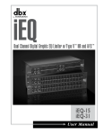
1
®
iEQ
Dual Channel Digital Graphic EQ/Limiter w/Type V™ NR and AFS ™
iEQ-15
iEQ-31
User Manual
IMPORTANT SAFETY INSTRUCTIONS
WARNING FOR YOUR PROTECTION
READ THESE INSTRUCTIONS:
CAUTION
RISK OF ELECTRIC SHOCK
DO NOT OPEN
A T T E N T I O N : RISQUE DE CHOC ELECTRIQUE - NE PAS OUVRIR
W A R N I N G : TO REDUCE THE RISK OF FIRE OR ELECTRIC
KEEP THESE INSTRUCTIONS
The symbols shown above are internationally accepted
symbols that warn of potential hazards with electrical
products. The lightning flash with arrowpoint in an equilateral triangle means that there are dangerous voltages
present within the unit. The exclamation point in an equilateral triangle indicates that it is necessary for the user to
refer to the owner’s manual.
FOLLOW ALL INSTRUCTIONS
SHOCK DO NOT EXPOSE THIS EQUIPMENT TO RAIN OR MOISTURE
These symbols warn that there are no user serviceable
parts inside the unit. Do not open the unit. Do not
attempt to service the unit yourself. Refer all servicing to
qualified personnel. Opening the chassis for any reason
will void the manufacturer’s warranty. Do not get the unit
wet. If liquid is spilled on the unit, shut it off immediately
and take it to a dealer for service. Disconnect the unit
during storms to prevent damage.
HEED ALL WARNINGS
DO NOT USE THIS APPARATUS NEAR WATER
CLEAN ONLY WITH A DRY CLOTH.
DO NOT BLOCK ANY OF THE VENTILATION OPENINGS. INSTALL IN ACCORDANCE WITH
THE MANUFACTURER’S INSTRUCTIONS.
DO NOT INSTALL NEAR ANY HEAT SOURCES SUCH AS RADIATORS, HEAT REGISTERS,
STOVES, OR OTHER APPARATUS (INCLUDING AMPLIFIERS) THAT PRODUCE HEAT.
ONLY USE ATTACHMENTS/ACCESSORIES SPECIFIED BY THE MANUFACTURER.
UNPLUG THIS APPARATUS DURING LIGHTNING STORMS OR WHEN UNUSED FOR LONG
PERIODS OF TIME.
Do not defeat the safety purpose of the polarized or grounding-type plug. A polarized plug has two blades with one wider than the other. A grounding type plug has
two blades and a third grounding prong. The wide blade or third prong are provided for your safety. If the provided plug does not fit your outlet, consult an electrician for replacement of the obsolete outlet.
Protect the power cord from being walked on or pinched particularly at plugs, convenience receptacles, and the point where they exit from the apparatus.
SAFETY INSTRUCTIONS
NOTICE FOR CUSTOMERS IF YOUR UNIT IS EQUIPPED
WITH A POWER CORD.
Use only with the cart stand, tripod bracket, or table specified by the manufacture,
or sold with the apparatus. When a cart is used, use caution when moving the
cart/apparatus combination to avoid injury from tip-over.
WARNING: THIS APPLIANCE MUST BE EARTHED.
The cores in the mains lead are coloured in accordance with
the following code:
GREEN andYELLOW - Earth
BLUE - Neutral
BROWN - Live
As colours of the cores in the mains lead of this appliance may
not correspond with the coloured markings identifying the terminals in your plug, proceed as follows:
• The core which is coloured green and yellow must
be connected to the terminal in the plug marked
with the letter E, or with the earth symbol, or
coloured green, or green and yellow.
• The core which is coloured blue must be connected to the terminal marked N or coloured black.
• The core which is coloured brown must be connected to the terminal marked L or coloured red.
This equipment may require the use of a different line cord,
attachment plug, or both, depending on the available power
source at installation. If the attachment plug needs to be
changed, refer servicing to qualified service personnel who
should refer to the table below. The green/yellow wire shall be
connected directly to the units chassis.
CONDUCTOR
WIRE COLOR
Normal
Alt
L
LIVE
BROWN
BLACK
N
NEUTRAL
BLUE
WHITE
E EARTH GND GREEN/YEL
GREEN
WARNING: If the ground is defeated, certain fault conditions in
the unit or in the system to which it is connected can result in
full line voltage between chassis and earth ground. Severe injury
or death can then result if the chassis and earth ground are
touched simultaneously.
Refer all servicing to to qualified service personnel. Servicing is required when
the apparatus has been damaged in any way, such as power-supply cord or plug is
damaged, liquid has been spilled or objects have fallen into the apparatus, the apparatus has been exposed to rain or moisture, does not operate normally, or has been
dropped.
POWER ON/OFF SWITCH: For products provided with a power switch, the power
switch DOES NOT break the connection from the mains.
MAINS DISCONNECT: The plug shall remain readily operable. For rack-mount or
installation where plug is not accessible, an all-pole mains switch with a contact
separation of at least 3 mm in each pole shall be incorporated into the electrical
installation of the rack or building.
FOR UNITS EQUIPPED WITH EXTERNALLY ACCESSIBLE FUSE RECEPTACLE: Replace fuse
with same type and rating only.
MULTIPLE-INPUT VOLTAGE: This equipment may require the use of a different line
cord, attachment plug, or both, depending on the available power source at installation. Connect this equipment only to the power source indicated on the equipment
rear panel. To reduce the risk of fire or electric shock, refer servicing to qualified
service personnel or equivalent.
This Equipment is intended for rack mount use only.
IMPORTANT SAFETY INSTRUCTIONS
U.K. MAINS PLUG WARNING
ELECTROMAGNETIC
COMPATIBILITY
This unit conforms to the Product
Specifications noted on the Declaration
of Conformity. Operation is subject to
the following two conditions:
• this device may not cause harmful
interference, and
• this device must accept any interference received, including interference
that may cause undesired operation.
Operation of this unit within significant
electromagnetic fields should be avoided.
• use only shielded interconnecting
cables.
A molded mains plug that has been cut off from the cord is unsafe.
Discard the mains plug at a suitable disposal facility. NEVER UNDER
ANY CIRCUMSTANCES SHOULD YOU INSERT A DAMAGED OR CUT
MAINS PLUG INTO A 13 AMP POWER SOCKET. Do not use the
mains plug without the fuse cover in place. Replacement fuse covers
can be obtained from your local retailer. Replacement fuses are 13
amps and MUST be ASTA approved to BS1362.
DECLARATION OF
CONFORMITY
Manufacturer’s Name:
Manufacturer’s Address:
dbx Professional Products
8760 S. Sandy Parkway
Sandy, Utah 84070, USA
declares that the product:
Product name:
Note:
Product option:
dbx iEQ 15 & dbx iEQ31
Product name may be suffixed by the
letters-EU.
None
conforms to the following Product Specifications:
Safety:
IEC 60065 (1998)
EMC:
EN 55013 (1990)
EN 55020 (1991)
Supplementary Information:
The product herewith complies with the requirements of the Low
Voltage Directive 72/23/EEC and the EMC Directive 89/336/EEC as
amended by Directive 93/68/EEC.
Vice-President of Engineering
8760 S. Sandy Parkway
Sandy, Utah 84070, USA
Date: March 26, 2003
European Contact:
Your local dbx Sales and Service Office or
Harman Music Group
8760 South Sandy Parkway
Sandy, Utah
84070 USA
Ph: (801) 566-8800
Fax: (801) 568-7583
iEQ
Table of Contents
Table of Contents
Defining the iEQ .....................................................i
Service Contact Info ...............................................ii
Warranty ..................................................................ii
Installation Recommendations...............................1
Power Up Quick Key Options ..............................1
Rear Panel Connections .........................................3
Front Panel Connections........................................3
Basic Connection....................................................6
Block Diagram ........................................................7
Specifications ..........................................................8
Table of Contents
®
iEQ User Manual
iEQ
iEQ Operation
®
iEQ
Introduction
INTRODUCTION
Congratulations on your purchase of the dbx Professional Products iEQ Series Graphic
Equalizer/Limiter with Type V™ noise reduction and AFS™. With an EQ heritage that has produced countless industry standard patents and dates back more than 30 years, the dbx iEQ 15
and iEQ 31 easily live up to the dbx legacy of uncompromised sonic integrity. In addition to
unsurpassed equalization specs, the iEQ series also offer built-in necessities which include
AFS™ Feedback Suppression, Type V™ Noise reduction and PeakStopPlus® limiting. Besides
including two 15-Band channels, 2/3 octave (iEQ 15) and two 31-band channels (iEQ 31) of
1/3-octave equalization, the iEQ 15 and iEQ 31 also offer +12 dB input gain range; switchable
+6 or +15 dB boost/cut range, 40mm faders, XLR, 1/4'' and Euroblock inputs and outputs, nonconductive nylon sliders; and an intuitive user interface with comprehensive output and gain
reduction metering. As always, the inevitable result of our meticulous attention to detail and
top-quality componentry is exceptional sound, performance, and reliability.
This manual will be your guide to understanding the full functionality of the powerful iEQ
series. After you have become familiar with the unit, we encourage you to experiment and find
creative ways that the iEQ series can help you optimize your specific application.
Defining the iEQ
The dbx iEQ Series Graphic Equalizer provide the user with the following features:
• Advanced Feedback Suppression (AFS™)
• Type V™ Noise Reduction
• PeakStopPlus® Limiting
• 1/3 & 2/3-octave Constant Q frequency bands
• Switchable boost/cut ranges of ±6 or ±15 dB
• 18 dB per octave 40Hz low-cut filter
• ±12 dB input gain range
• XLR,TRS and Euroblock Inputs and Outputs
• Internal Toroidal Transformer
• Dynamic range of greater than 113dB
• User Power Up Features
• Relay Bypass for Power Failure System Protection
i
®
iEQ User Manual
iEQ
Introduction
Service Contact Info
If you require technical support, contact dbx Customer Service. Be prepared to accurately
describe the problem. Know the serial number of your unit - this is printed on a sticker attached
to the top panel. If you have not already taken the time to fill out your warranty registration
card and send it in, please do so now.
Before you return a product to the factory for service, we recommend you refer to the manual. Make sure you have correctly followed installation steps and operation procedures. If you
are still unable to solve a problem, contact our Customer Service Department at (801) 568-7660
for consultation. If you need to return a product to the factory for service, you MUST contact
Customer Service to obtain a Return Authorization Number.
No returned products will be accepted at the factory without a Return Authorization Number.
Please refer to the Warranty information on the following page, which extends to the first enduser. After expiration of the warranty, a reasonable charge will be made for parts, labor, and
packing if you choose to use the factory service facility. In all cases, you are responsible for
transportation charges to the factory. dbx will pay return shipping if the unit is still under warranty.
Use the original packing material if it is available. Mark the package with the name of the shipper and with these words in red: DELICATE INSTRUMENT, FRAGILE! Insure the package properly. Ship prepaid, not collect. Do not ship parcel post.
Warranty
This warranty is valid only for the original purchaser and only in the United States.
1. The warranty registration card that accompanies this product must be mailed within 30 days
after purchase date to validate this warranty. Proof-of-purchase is considered to be the burden of the consumer.
2. dbx warrants this product, when bought and used solely within the U.S., to be free from
defects in materials and workmanship under normal use and service.
3. dbx liability under this warranty is limited to repairing or, at our discretion, replacing defective materials that show evidence of defect, provided the product is returned to dbx WITH
RETURN AUTHORIZATION from the factory, where all parts and labor will be covered up to
a period of two years. A Return Authorization number must be obtained from dbx by telephone. The company shall not be liable for any consequential damage as a result of the product's use in any circuit or assembly.
4. dbx reserves the right to make changes in design or make additions to or improvements upon
this product without incurring any obligation to install the same additions or improvements
on products previously manufactured.
5. The foregoing is in lieu of all other warranties, expressed or implied, and dbx neither assumes
nor authorizes any person to assume on its behalf any obligation or liability in connection
with the sale of this product. In no event shall dbx or its dealers be liable for special or consequential damages or from any delay in the performance of this warranty due to causes
beyond their control.
®
iEQ User Manual
ii
Operation
iEQ
Installation / User Power-Up Modes
Installation Recommendations
FOR RACK MOUNT USE ONLY - Install the iEQ in your rack with the provided rack screws.
When installed in a rack, the unit should be positioned with enough room (at least one 1U
above the and 1U below the unit) to allow proper ventilation. The iEQ should not be mounted above or below anything that generates excessive heat. Ambient temperatures should not
exceed 1130F (450C) when equipment is in use. Although the unit is shielded against radio frequency and electromagnetic interference, extremely high fields of RF and EMI should be avoided where possible.
User Power-Up Modes
Unlike conventional graphic equalizers of the past, the iEQ Series EQs offer you the ability to
lockout access to frequency slider manipulation and reset AFS filter settings. The procedure for
these functions are as follows:
1. Entry
While applying power, press and hold the <AFS> button on CHANNEL 1 until the following
LED display sequence pattern on Ch1 Meters briefly appears:
Power Up Prompt
Channel 1
2. Menus
Sy
ste
Liv m L
e F ock
ou
il
AF ter L t
S
i
f
tT
6-F No
im
ixe rma
e
d/6 l v
s
-L .
ive
To select any one of the three available option (which are: 1. System Lockout 2. Live Filter Lift
Time Menu, and 3. AFS Normal vs. 6-Fixed/6-Live Menu), press the <AFS> button on CHANNEL 1 to select through 1 of 3 menus. The meter LEDs appear as follow:
CHANNEL
Power Up Menu
3. Selections
Sy
ste
Sy m U
ste nlo
c
m
Lo ked
ck
ed
System Lockout - Press the <AFS> button on CHANNEL 2 to select through selections within menus. The selections for System Lockout are : System Unlocked and System Locked and
will be represented by a lit LED once selected. The following illustration show the selections
and the corresponding LEDs indicators:
System Lockout Menu
1
CHANNEL 2
®
iEQ User Manual
iEQ
User Power-Up Modes Cont’d
Operation
Liv
eF
Liv
Liv
eF
ilte
r
L
ilte ift O
r L ff
eF
if
ilte t Sh
or
rL
t
ift
Lo
ng
Live Filter Lift Time Menu - Press the <AFS> button on CHANNEL 2 to select through selections
within menus. The selections for System Lockout are: Live Filter Lift Off, Live Filter Lift Short and
Live Filter Lift Long, and will be represented by a lit LED once selected. The following illustration show the selections and the corresponding LEDs indicators:
CHANNEL 2
Live Filter Lift Time Menu
AFS Normal vs. 6-Fixed/6-Live Menu
ixe
6-F
AF
S
Mo
rm
a
d/6 l (Al
l
-L
ive Live
Mo FIl
de ters
)
AFS Normal vs. 6-Fixed/6-Live - Press the <AFS> button on CHANNEL 2 to select through selections within menus. The selections for System Lockout are: AFS Normal Mode (All 12 filters are
live) and AFS Normal vs 6-Fixed/6-Live Menu, and will be represented by a lit LED once selected. The Fixed filters stay closed until cleared, and live filters continuously update in the order
that they were set. The following illustration show the selections and the corresponding LEDs
indicators:
CHANNEL 2
4. Exit
Once your selections have been made, press and hold the <AFS> button on CHANNEL 1 until
Filter Clear LED Sequence on CH1 Meters appears to exit.
®
iEQ User Manual
2
Operation
iEQ
Rear Panel Connections
Rear Panel Connections
iEQ15 - dual channel 15 band graphic equalizer
iEQ31 - dual channel 31 band graphic equalizer
Power Cord Receptacle: Connects AC power to the equalizer.
Power Switch: Switches the power on and off. Always make audio connections with the power
switch in the off position.
Input Connectors: Three types of input connectors are provided for input connections: female
locking XLR type connectors, 1/4” tip-ring-sleeve phone jack connectors, and Euroblock. The
maximum input level that the equalizer can accept is +20dBu (ref: 0.775Vrms).
Output Connectors: Three types of output connectors are provided for output connections:
male XLR type connectors, 1/4” tip-ring-sleeve phone jack connectors and Euroblock.
Front Panel Connections
iEQ15 - dual channel 15 band graphic equalizer
3
®
iEQ User Manual
iEQ
Front Panel Connections
Operation
iEQ31 - dual channel 31 band graphic equalizer
Input Gain Control: This control sets the signal level to the equalizer. It is capable of -12dB
to +12dB of gain. Its effect is apparent by viewing the OUTPUT LEVEL BAR GRAPH.
EQ Bypass: This switch removes the graphic equalizer section from the signal path. The
BYPASS switch does not, however, affect the INPUT GAIN, AFS, or LOW CUT filters. This button lights red when the EQ is in bypass mode
Boost/Cut Range Selection Switch: This switch selects which of the two boost/cut ranges the
equalizer will use, either ±6dB or ±15dB. The button lights red when the ±15dB range is selected.
Output Level Bar Graph: These four LEDs indicate output level of the equalizer. It monitors
the level at the output of the equalizer after all other processing, including the limiter.
Clip LED: This LED lights whenever any internal signal level reaches 1dB below clipping which
may occur when any of the following happen: 1) the input signal is “hotter” than +20dBu, 2)
excessive gain is applied by the input gain control, or 3) excessive boost is applied using the
frequency sliders.
Gain Reduction Meter: These four LEDs indicate the amount of gain reduction being induced
by the setting of the PeakStopPlus® LIMITER THRESHOLD control as the signal level from the
graphic EQ section exceeds this limiter threshold setting.
PeakStopPlus® Limiter Threshold Control: This control engages the PeakStopPlus™ limiter.
It sets the threshold level at which :1 gain reduction will begin to occur. It is capable of a
range of 0dBu through “OFF” (+20dBu). When the threshold control is set to “OFF”, the limiter
is effectively disabled, and no gain reduction will occur.
AFS™ (Advanced Feedback Suppression) Switch: This control engages the AFS function of
the iEQ 15 and 31 If AFS is Off, the filters are bypassed, and the algorithm is halted (the filters
are not updated). If AFS is On, the filters are activeThe AFS modes are as follows:
AFS Mode:
AFS Button LED Color:
Off
Off
Music Low
Green
Music Medium
Yellow
Music High
Red
Lift times are set up at power-up:
Off
Short 10 Minutes
Long
60 Minutes
Bandwidth:
Q:
1/10 Octave
1/20 Octave
1/80 Octave
14.5
29
116
®
iEQ User Manual
4
Operation
iEQ
Front Panel Connections Cont’d
The iEQ 15 and 31 offer the exclusive patent pending AFS (Advanced Feedback Suppression)
feedback elimination module. The AFS uses Precision Frequency Detection and state-of-the-art
processing to determine the exact portions of a given frequency of your feedback that need to
be removed (instead of taking out large sections of your sound). For more detailed information regarding AFS, please visit the AFS white paper section at www.dbxpro.com.
The AFS module of the iEQ 15 and 31 allow the user to optimize the elimination of feedback.
In the past, graphic equalizers were used to eliminate feedback from a system. This was an
acceptable method for eliminating feedback, but when this method was precision tested, the
result clearly showed that a single 1/3 octave EQ slider was removing approximately half of the
signal power. With the AFS, the module removes the feedback automatically and the proprietary, precision AFS filters remove only a fraction of the frequency spectrum. The following
diagram shows AFS as opposed to competing, competitive feedback eliminators and conventional
graphic EQs:
dbx AFS™
Competitor’s
Feedback
Elimination
1/3 Octave EQ
dbx Type V™ Noise Reduction: This button engages (when lit) the dbx Type V™ Noise
Reduction circuit within the EQ. Typically, graphic equalizers raise the noise floor within the
signal path, and dbx’s proprietary Type V™ noise reduction will reduce the apparent noise floor
through its simultaneous encode/decode process (shown below). The button lights when the
dbx Type V™ Noise Reduction circuit is activated.
Simultaneous Encode/Decode Control
Type V™
Encode
Audio
EQ
Audio
Type V™
Decode
Frequency Band Slider Controls: Each one of these slider potentiometers will boost or cut at
its noted frequency by ±6dB or ±15dB, depending upon the position of the BOOST/CUT
RANGE switch. When all the sliders are in the center detented position the output of the equalizer is flat. The frequency band centers of the iEQ-31 are marked at 1/3rd of an octave intervals on ISO standard spacings, while the frequency band centers of the iEQ-15 are marked at
2/3rds of an octave intervals on ISO standard spacings.
Low Cut Enable: The LOW-CUT button inserts (when lit) or removes the 18dB/octave 40Hz
Bessel low-cut filter from the signal path. When the LOW-CUT switch is pushed in, the LOWCUT filter is IN the audio path.
5
3iEQ User Manual
®
iEQ
Basic Connection
Operation
Basic Connection of the iEQ
The iEQ Series Equalizers have balanced inputs and outputs that can be used with any balanced
or unbalanced line-level device.
To connect the equalizer to your sound system refer to the following steps:
• Turn off all equipment before making connections.
• Mount equalizer in a standard-width rack.
Install the EQs in a rack with the rack screws provided. It can be mounted above or below
anything that does not generate excessive heat. Ambient temperatures should not exceed
113° F (45°C) when equipment is in use. Although the unit’s chassis is shielded against radio
frequency and electromagnetic interference, extremely high fields of RF and EMI should be
avoided.
• Make audio connections via XLR, 1/4” TRS jacks or Euroblock connectors according to application needs. All three types of connectors for the inputs and outputs can be used for balanced
or unbalanced connections. The use of more than one connector at a time for the inputs could
unbalance balanced lines, cause phase cancellation, short a conductor to ground, or cause damage to other equipment connected to the equalizer. More than one output may be used simultaneously as long as the combined parallel load is greater than 600 .
• Select the operating range with the boost/Cut range selection switch
Note: Be sure to reduce audio levels at the power amplifiers when changing the setting of this
switch as it may generate an audible transient.
• Apply power to the equalizer. Connect the AC power cord to the AC power receptacle on the
back of the equalizer. Route the AC power cord to a convenient power outlet away from audio
lines. The unit may be turned on and off from the rear panel power switch or a master equipment power switch. Since the iEQ Series Equalizers consume a relatively small amount of power,
the units may be left on continuously.
®
iEQ User Manual
6
Inputs
RF Filter
Input
Input
Gain
TYPE IV™
Front
Panel
Slide Pots
Limiter
A/D
A/D
CLIP Detect
Type V™ NR
EQ Bypass
Low Cut
Range
Relay
Bypass
DSP
Micro
Processor
D/A
AFS (Red LED)
Gain Reduction
Output meter
RF
Filter
Outputs
dbx iEQ 15 and 31 Graphic Equalizer
Block Diagram
Programmable
Logic
AFS (Green LED)
®
7
iEQ User Manual
iEQ
Block Diagram
Operation
Block diagram
...
iEQ
Operation
Specifications
Specifications
Inputs
Connectors:
Type:
Impedance:
Max Input Level:
CMRR:
1/4” TRS, female XLR (pin 2 hot), and Euroblock
Electronically balanced/unbalanced, RF filtered
Balanced 40k , unbalanced 20k
+22dBu balanced or unbalanced
>40dB, typically >55dB at 1kHz
Outputs
Connectors:
Type:
Impedance:
Max Output Level:
1/4” TRS, male XLR (pin 2 hot), and Euroblock
Balanced/unbalanced, RF filtered
Balanced 120 , unbalanced 60
+20dBu balanced/unbalanced into 2k or greater
System Performance
Frequency Response:
Dynamic Range:
THD+Noise:
Interchannel Crosstalk:
Noise Reduction:
Digital Resolution:
Sample Frequency:
Latency:
20Hz to 20kHz, +0.5/-0.25dB
>113dB, “A” weighted
0.003% typical at +4dBu, 1kHz
<-80dB, 20Hz to 20kHz
Up to 10dB of dynamic broadband noise reduction
24 bits
48kHz
2msec
Function Switches
AFS™:
TYPE V™ NR:
EQ Bypass:
Low Cut:
Range:
Activates dbx AFS™ Advanced Feedback Suppression
Activates dbx Type V™ Noise Reduction
Bypasses the graphic equalizer section in the signal path
Activates the 40Hz 18dB/octave Bessel high-pass filter Range
Selects either +/- 6dB or +/- 15dB slider boost/cut range
Indicators
Output Level:
Gain Reduction:
Type V™ NR:
EQ Bypass:
Clip:
Low Cut:
+/-15dB:
4-LED bar graph (Green, Green, Yellow, Red) at -10, 0, +10, and +18dBu
4-LED bar graph (all Red) at 0, 3, 6, and 10dB
1 LED: yellow, green or red
1 LED: red
1 LED: red
1 LED: red
1 LED: red
Power Supply
Operating Voltage:
Power Consumption:
Mains Connection:
120VAC 60Hz, 220-240VAC 50/60Hz
17 Watts
IEC receptacle
Physical
Dimensions:
iEQ15:
3.5” H X 19” W X 7.9” D (8.9cm x 48.3cm x 20.1cm)
iEQ31:
5.25” H X 19” W X 7.9” D (13.4cm x 48.3cm x 20.1cm)
Dimensions (h x l x p):
Weight:
iEQ15:
7.5 lbs.
iEQ31:
9.25 lbs.
Shipping Weight:
iEQ 15:
8.5 lbs.
iEQ 31:
10.25 lbs.
Note: Specifications subject to change.
®
iEQ User Manual
8
®
A Harman International Company
8760 South Sandy Pkwy.
Sandy, Utah 84070
Phone: (801) 568-7660
Fax: (801) 568-7662
Questions or comments?
E•mail us at: [email protected]
or visit our World Wide Web home page at:
www.dbxpro.com
18-1904-A