1
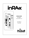
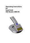
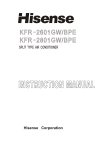
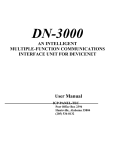
Manual
Compact Reader ARE I2
Installation Guide
for Systems with a
Serial Interface (RS 232)
Manual
Page 2 / 33- Revision 01
ARE I2 / RS 232 – Installation Guide
Contents
1
INTRODUCTION
5
2
SYSTEM OVERVIEW
5
3
START-UP PROCEDURE
6
4
INSTALLATION
7
4.1
Mounting of the Housing
7
4.2
Grounding of the Reader
7
4.3
Assemblage of the Line Connectors
4.3.1
Allowed Diameter of the Used Cables
4.3.2
Assembling of the Cable Pipe
4.3.3
Mounting of the Power Supply Cable
Assembling of the Power Supply and Data Cable (Single Cable Pipe)
4.3.5
Final Assembly of the Cable Pipe
4.3.6
Plug in of the SAB Cab
4.3.7
Using the Service Cable ID 70213
4.3.8
Using the Power Supply and Data Cable ID 70212
7
8
8
9
10
11
11
12
13
4.4
13
Power Supply
5
VISUAL SIGNAL LAMPS
14
6
SETTINGS OF THE READER / MOST IMPORTANT PARAMETERS
15
6.1
General
15
6.2
Error Codes
16
6.3
CID – Suppression of ID Codes
16
6.4
CN – Suppression of No Reads
17
6.5
NID- Failure Protection
17
6.6
EC- Echo
19
AEG
Identifikationssysteme GmbH
Söflinger Straße 100
D-89077 Ulm
Tel. ++49(0)731-933-1340/1877
Fax ++49(0)731-933-1855
e-mail: [email protected]
Manual
Page 3 / 33- Revision 01
ARE I2 / RS 232 – Installation Guide
6.7
BD- Baudrate
19
6.8
TOR – Maximum Reading Time
20
6.9
VS- Show Parameter
20
6.10
VSAVE – Save Parameter
20
7
21
OPERATING MODES OF THE READER
7.1
Mode 2 – Triggered by an Software Command
7.1.1
Settings of the Reader / Most Used Parameters
7.1.2
Basic Data Exchange Process
7.1.3
ReadOnly-Transponder
7.1.4
R / W –Transponder
7.1.4.1
Standard Read Process / Serial Number of the Transponder
7.1.4.2
Selective Read RD
7.1.4.3
Writing Process WD
GT
7.2
Operating Mode 0 - Continuous Reading
7.2.1
Settings of the Reader / Most Used Parameters
8
21
22
23
23
23
23
24
24
26
26
28
INSTRUCTIONS
8.1
General Instructions
28
8.2
Special Instructions for Using a Read / Write System
29
9
30
HOTLINE
10
REFERENCE DOCUMENTATION
30
11
REVISIONS
30
12
APPENDIX
31
12.1
Best Orientation for an F-Type -Reader
31
12.2
Best Orientation for an L-Type -Reader
32
12.3
Assembling of the SAB Cab
33
AEG
Identifikationssysteme GmbH
Söflinger Straße 100
D-89077 Ulm
Tel. ++49(0)731-933-1340/1877
Fax ++49(0)731-933-1855
e-mail: [email protected]
Manual
Page 4 / 33- Revision 01
ARE I2 / RS 232 – Installation Guide
AEG
Identifikationssysteme GmbH
Söflinger Straße 100
D-89077 Ulm
Tel. ++49(0)731-933-1340/1877
Fax ++49(0)731-933-1855
e-mail: [email protected]
Manual
Page 5 / 33- Revision 01
ARE I2 / RS 232 – Installation Guide
1
Introduction
This document will describe the components of the Compact Reader System ARE I2 / RS 232
and the procedure how to do the first set up of the reader.
The main features of the reader are listed below:
• the antenna is placed inside of the housing (base version)
• there are algorithm available to read nearly all 125 kHz-transponders on market
• the serial RS 232-Interface is placed inside of the housing, allowed baud rate are up to
19200 Bit/s
• the allowed supply voltage is 9 to 30VDC
• low power consumption of reader < 1.2 Watt
• high reliability for reading and writing within an industrial environment.
• compact housing of the reader with multiple ways for mounting.
• the cabling concept of the reader is optimised to service demands.
• the protection class of the housing is IP65
• there is a set of external antennas available to meet special application demands ( X-tended
version)
2
System Overview
In the base version all electronic components of the reader is placed inside of a small plastic
housing.
24VDC
Transponder
Reader with
Integrated Antenna
(9-Pin SubD)
RS232
ARE I2
Figure 2-1: Concept of the Reading System
AEG
Identifikationssysteme GmbH
Söflinger Straße 100
D-89077 Ulm
Tel. ++49(0)731-933-1340/1877
Fax ++49(0)731-933-1855
e-mail: [email protected]
Manual
Page 6 / 33- Revision 01
ARE I2 / RS 232 – Installation Guide
The connection of the cables (power supply and data transfer) is done inside of the connection
cab (SAB Cab). Together with an sealing element a protection classification of IP 65 is guaranteed.
By means of the integrated antenna the reader generates an alternating magnetic field, which
powers the transponder. Coded signals sent back from the transponder are received and decoded by the reader
The reader is fully controlled by an Master with RS 232 data port, while using the integrated
serial RS 232 Interface of the reader.
The side of the housing showing the antenna symbol must not be brought next to a metal surface. This could lead to a significant change of the properties of the antenna circuit, which in
turn reduces the reading range considerably.
Environmental electromagnetic noise may also reduce the specified reading performance.
Special hints to overcome these problems are documented in Chapter 8.
3
Start-up Procedure
The start-up procedure of the reader system is split up to following steps:
• mounting of the reader and pin connection (cabling), see Chapter 4
• operational instructions, see Chapter 7
To get a feeling how the IdentSystem will work, first start the reader controlled by the serial interface (RS 232) of an isolated PC.
The next step is to integrate the reader to the operating network.
AEG
Identifikationssysteme GmbH
Söflinger Straße 100
D-89077 Ulm
Tel. ++49(0)731-933-1340/1877
Fax ++49(0)731-933-1855
e-mail: [email protected]
Manual
Page 7 / 33- Revision 01
ARE I2 / RS 232 – Installation Guide
4
Installation
To get the specified reading performance it is necessary to do the installation carefully step by
step as it is described in the following Chapters. All the work must be done by well educated
people.
4.1
Mounting of the Housing
The reader can be mounted to any other mechanic construction. It is recommended to protect
the housing against heavy mechanical interactions.
Attention!
The side of the housing showing the antenna symbol must not be brought next to a metal
surface. This could lead to a significant change of the properties of the antenna circuit,
which in turn reduces the reading range considerably.
With the help of the plastic bars, the reader can mounted or screwed on to the most fastening
elements without open the housing of the device.
4.2
Grounding of the Reader
To get reliable reading results, the reader must be grounded. The connector is place at the side
of the housing (6.35 mm flat contact).
To avoid EMV-problems, the cable to ground ought to be very short with low impedance.
Attention! The topology of the ground wires must be done in the right way (according state of
art).
4.3
Assemblage of the Line Connectors
The connection of the power supply and data transfer cables are done by using the connectors
of the SAB Cab. The Assemblage inside of the SAB Cab is described in Chapter 4.3.1 to
4.3.7.
AEG
Identifikationssysteme GmbH
Söflinger Straße 100
D-89077 Ulm
Tel. ++49(0)731-933-1340/1877
Fax ++49(0)731-933-1855
e-mail: [email protected]
Manual
Page 8 / 33- Revision 01
ARE I2 / RS 232 – Installation Guide
Inside of the SAB Cap there are the pins of following connections:
• power supply
• data link to the serial interface RS232
The codes to order the SAB Cabs and preassembled cables are listed below:
ID 70212
ID 70213
ID 70221
ID 70215
ID 70219
SAB-Cab incl. one PG9 cable pipe and 5 wire cable (standard cable)
SAB-Cab incl. one PG9 cable pipe and 5 wire cable / Sub D 9 Connector
(Service Cable)
SAB-Cab incl. one PG9 cable pipe
SAB-Cab incl. two PG9 cable pipes
SAB Cab without any cable pipe. The cabling is done by the customer himself.
4.3.1 Allowed Diameter of the Used Cables
The allowed diameters of the cables used for data link and power supply must be in the range
from ∅3,5 to ∅8mm. For this case, IP 65 is reached.
4.3.2 Assembling of the Cable Pipe
If no preassembled SAB Cab are used (Best-Nr. ID 70214), the assembling must be done in
following way:
• Breakthrough the prepared areas at the surface of the SAB Cabs. There are two prepared
areas seen at the SAB Cab: central and at one side of the cab.
• The sealing must be done in the correct way O-Ring (3) at the cable pipe (4) (see also
Figure 4-1.
2
4
3
1
Figure 4-1:Assembling oft the Cable Pipe
• Bring the nut (2) of the cable pipe inside of the SAB Cab (1).
• To fasten the nut please use the right tool (17mm)..
AEG
Identifikationssysteme GmbH
Söflinger Straße 100
D-89077 Ulm
Tel. ++49(0)731-933-1340/1877
Fax ++49(0)731-933-1855
e-mail: [email protected]
Manual
Page 9 / 33- Revision 01
ARE I2 / RS 232 – Installation Guide
4.3.3 Mounting of the Power Supply Cable
The power supply cable must be mounted in following steps:
• Remove all inner parts from the cable pipe at the SAB Cab (1) ( nut (5), pipe(4) and cable
fastener (3)) (see Figure 4-2)
• Put all the removed parts ( nut (5), pipe (4), cable fastener (3)) and the cable pipe of the
SAB Cab as well (1 to 4) to the cable.
5
4
3
Cable
6
1
7
Figure 4-2: Arranged Parts for Mounting
• Remove the outer isolation of the cable at a length of 6cm .
• Remove the isolation of the wires at a length of 6 [mm] and stick a covering hull to the litz
wire.
• Put the cable to the cable pipe. The length of the cable coming out the SAB Cab must long
enough to do all further installation steps in an easy way.
• Stick the pipe (4) into the cable fastener (3).
• Stick the cable fastener (3) into the cable pipe.
• Connect the power supply cable into the right places of the MINI-COMBICON-Connector
(see Figure 4-2 Part (6)).
• The pin assignment is shown in the figure below.
AEG
Identifikationssysteme GmbH
Söflinger Straße 100
D-89077 Ulm
Tel. ++49(0)731-933-1340/1877
Fax ++49(0)731-933-1855
e-mail: [email protected]
Manual
Page 10 / 33- Revision 01
ARE I2 / RS 232 – Installation Guide
green
black
B
NC
A
+US
RXD
C
-
-US
TXD
L
GND (0V)
+
UL
+9..30VDC
D
E
V+DC
shielding
NC
ARE I2
4.3.4 Assembling of the Power Supply and Data Cable (Single Cable Pipe)
The connection of the cable is also done inside of the SAB Cab. Instead of an 2-wire power
supply cable there is now an 5-wire data cable needed. The diameter of the inner wires must
be big enough to keep the voltage drop in the specified range.
The steps to mount the cable is decried in Chapter 4.3.3.
green
black
shielding
RxD (reader)
TxD (reader)
GND
B
+US
RXD
D
-
-U S
TXD
L
GND (0V)
+
UL
+9..30VDC
C
E
V+DC
NC
A
shielding
NC
ARE I2
AEG
Identifikationssysteme GmbH
Söflinger Straße 100
D-89077 Ulm
Tel. ++49(0)731-933-1340/1877
Fax ++49(0)731-933-1855
e-mail: [email protected]
Manual
Page 11 / 33- Revision 01
ARE I2 / RS 232 – Installation Guide
4.3.5 Final Assembly of the Cable Pipe
• Pull by and by all the cable back, until the isolation of the cables are near to beginning of
the cable pipes.
• Fasten nuts (5) of the cable pipes with the right tool (17mm).
• Do this carefully, to ensure the tightness of the protection class of IP 65..
• Plug the finished assembled MINI-COMBICON-Connector to the SAB Cab. Take care of
the correct coding ((7) in Figure 4-2) of the connectors.
4.3.6 Plug in of the SAB Cab
Attention:
Before plugging the SAB Cab to the connectors of the reader, make sure that the
grounding of the device is well done. Otherwise the electronic may be destroyed by electrostatic discharge (ESD).
1
B
A
2
Figure 4-3: Plug on the SAB Cab
•
•
•
•
Put on the sealing 2 to the SAB Cab (A).
Plug in the SAB Cab to the connector at the bottom of the reader device (B).
There is only one way to plug in the SAB Cab to the connector rim of the reader.
Fasten the SAB Cab with the help of the screws.
AEG
Identifikationssysteme GmbH
Söflinger Straße 100
D-89077 Ulm
Tel. ++49(0)731-933-1340/1877
Fax ++49(0)731-933-1855
e-mail: [email protected]
Manual
Page 12 / 33- Revision 01
ARE I2 / RS 232 – Installation Guide
4.3.7 Using the Service Cable ID 70213
Using the Service Cable, no special assembly work inside of the SAB Cab has be done by the
customer. After making the link to a power supply and plug in the Sub D 9 Connector to the
Com Data Port of an PC, the reader is ready to work.
:
power supply:
brown =
+ 9 ...30 Volt
white =
Ground
RS232
( 9 Pins Sub-D female)
1
2
3
RXD
TxD (reader)
shielding
TXD
GND (0V)
RxD (reader)
V+ (+24V)
4
5
ARE I2
GND
6
7
green
8
black
B
9
A
+US1
D
-US1
C
+US2
E
-US2
V+DC
AEG
Identifikationssysteme GmbH
Söflinger Straße 100
D-89077 Ulm
Tel. ++49(0)731-933-1340/1877
Fax ++49(0)731-933-1855
e-mail: [email protected]
Manual
Page 13 / 33- Revision 01
ARE I2 / RS 232 – Installation Guide
4.3.8 Using the Power Supply and Data Cable ID 70212
Using the Power Supply and Data Cable, no special assembly work inside of the SAB Cab has
be done by the customer. After making the link to a power supply and to the connector block
of Serial Data Port, the reader is ready to work.
4.4
power supply:
brown =
white =
+ 9 ...30 Volt
Ground
serial Interface:
RS 232
green =
yellow =
grey =
RxD ( reader receives data‘s )
TxD ( reader sends data‘s )
ground
Power Supply
The device is designed for DC Current with an voltage in the range between 9. to .30VDC. The
minimum power of the power supply is 1.2 Watt. There no need to use special cable to supply
the device.
Attention!
The minimum voltage at the at the readers input mustn’t be lower then 9V.
AEG
Identifikationssysteme GmbH
Söflinger Straße 100
D-89077 Ulm
Tel. ++49(0)731-933-1340/1877
Fax ++49(0)731-933-1855
e-mail: [email protected]
Manual
Page 14 / 33- Revision 01
ARE I2 / RS 232 – Installation Guide
5
Visual Signal Lamps
To show the operational state or results there are 5 LED at the
side of the housing.
BFH
ID
Moderne elektronische
Objekterkennung und Verfolgung
L1:
twinkles, if the processor works.
L2:
lit, if the latest reading process was successful
L3:
lit, if the latest reading process was a NoRead
L4:
lit, if the reader receives data’s at the serial data
port ( Rx )
L5:
lit, if the reader sends data’s at the serial data port
( Tx )
ARE I2
L1
L2
L3
L4
L5
AEG
Identifikationssysteme GmbH
Söflinger Straße 100
D-89077 Ulm
Tel. ++49(0)731-933-1340/1877
Fax ++49(0)731-933-1855
e-mail: [email protected]
Manual
Page 15 / 33- Revision 01
ARE I2 / RS 232 – Installation Guide
6
Settings of the Reader / Most Important Parameters
The default value of the operating mode parameter is 2..
• MD 2
• MD 0
6.1
triggered by an software command – default value
continuos mode
General
The command set described below defines the transfer of data on the serial interface.
The commands consist of a command code and optionally of a parameter value. Commands
are terminated by the control character <CR> (13h). The control character serves as command line terminator.
Command codes and parameters, that means all letters and numerical values, are principally transmitted as a sequence of ASCII characters (the value 255 (decimal) consequently
as 32H, 35H, 35H; the command RST as 52H, 53H, 54H).
The protocol format is as follows
command <SP> parameter <CR>
The space character <SP> separates commands from parameters and the <CR> character
acts as command line terminator.
For commands without parameter values (e.g. GT ) the <SP> character and parameter values are omitted. The command line is as short as this:
command <CR>.
Generally, every input terminated by <CR> is acknowledged by the reader. The following
response protocols are different:
Generally, every input terminated by <CR> is acknowledged by the reader. The following
response protocols are different:
AEG
Identifikationssysteme GmbH
Söflinger Straße 100
D-89077 Ulm
Tel. ++49(0)731-933-1340/1877
Fax ++49(0)731-933-1855
e-mail: [email protected]
Manual
Page 16 / 33- Revision 01
ARE I2 / RS 232 – Installation Guide
After entering a valid command together with a parameter value, the system answers by
sending the parameter value and <CR>. Example:
Command:
Output:
MD <SP> 2 <CR>
2 <CR>
After entering an invalid parameter value, the system answers with the corresponding error
code
Parameter settings can be queried by sending the command without adding an parameter
value. Example:
Command:
Output:
MD <CR>
1 <CR>
If a single <CR> is input, the reader answers with a single <CR>. Example:
Command:
Output:
<CR>
<CR>
Please note: If echo mode is active, a single <CR> forces the reader to output <CR> <CR>
(echo plus output).
6.2
Error Codes
If a command is not entered correctly, the reader sends one of the following error codes:
Wrong command:
Wrong parameter:
6.3
<NAK> #00 <CR>
<NAK> #02 <CR>
CID – Suppression of ID Codes
With CID=1 only the first of in succession identical transponder numbers is output on the
serial interface. The possibly following identical transponder numbers are suppressed, as
long as no new valid transponder number is received, processed and output. NoReads do
not influence the data filtering.
AEG
Identifikationssysteme GmbH
Söflinger Straße 100
D-89077 Ulm
Tel. ++49(0)731-933-1340/1877
Fax ++49(0)731-933-1855
e-mail: [email protected]
Manual
Page 17 / 33- Revision 01
ARE I2 / RS 232 – Installation Guide
Input format:
CID <SP> parameter <CR>
Parameter:
Value
0
1
Function
no filter function , (default value)
suppression of repeatedly read IDs
Please note: The CID parameter is only active, if the GT-Command is applied or the reader is
in the Continuos Reading Mode. In the MD 2 anyway a <CR> is sent to the master.
6.4
CN – Suppression of No Reads
Through the setting CN=1 all NoRead results are suppressed on the serial interface..
Input format:
CN <SP> parameter <CR>
Parameter:
Value
Function
0
issue NoReads on serial interface; (default value)
1
suppress NoReads on interface
Output (example): 0 <CR>
Please note: The CN parameter is only active, if the GT-Command is applied or the reader is in
the Continuos Reading Mode. In the MD 2 any way a <CR> is sent to the master.
6.5
NID- Failure Protection
NID specifies the number of identical transponder numbers, which have to appear for the
result “successful reading“ within a reading cycle. In the setting NID = 1, two successive
readings have to show the same transponder number.
Input format:
NID <SP> parameter <CR>
Parameter:
Value
Function
AEG
Identifikationssysteme GmbH
Söflinger Straße 100
D-89077 Ulm
Tel. ++49(0)731-933-1340/1877
Fax ++49(0)731-933-1855
e-mail: [email protected]
Manual
Page 18 / 33- Revision 01
ARE I2 / RS 232 – Installation Guide
0
1
Output (example):
one out of one (no effect)
two out of two ; (default value)
1 <CR>
Sequence of readings
Length of the reading cycle
NoRead
1 reading
0000125ED1, 0000125ED1
2 readings
0000125ED1, 0000126ED1
2 readings
Schedule 6-: example for a reading cycle with NID=1
Result of the reading cycle
NoRead
0000125ED1
NoRead
Example: A, B, C are specific different transponder numbers, N is NoRead:
Sequence of reading cycles
Output sequence after
filtering with CN=0 and
CID=1
N, N, ......,N, A, A, A, ....A, N,N, .........
N, N, ......,N, A, N, N,
.......
N. N, N, A, A, A, N, A, A, B, A, C, C, C, ....... N. N, N, A, N, B, A, C,
.....
N, N, B, B, B, B, B, N, N, N, B, B, B, B, N,
N, N, B, N, N, N, N, N,...
N,...
N, N, N, B, B, B, B, B, N, B, B, B, B, N, N, N, N, N, N, B, N, N, N, N,
....
....
Table 6-: example for the effect of the CID function
Output sequence after
filtering with CN=1 and
CID=1
A
A, B, A, C
B
B
Annotation:
The internal reference number is deleted in the following conditions:
• after a cold start
• after a warm start
• after entering the command line CID <SP> 1 <CR>
This causes that the next transponder code is output definitely.
Caution:
The filter function CID picks up the results of the complete reading
cycles, while the parameter NID proceeds from the results of single
readings! The filter function CID has effect on the serial interface
only.
AEG
Identifikationssysteme GmbH
Söflinger Straße 100
D-89077 Ulm
Tel. ++49(0)731-933-1340/1877
Fax ++49(0)731-933-1855
e-mail: [email protected]
Manual
Page 19 / 33- Revision 01
ARE I2 / RS 232 – Installation Guide
6.6
EC- Echo
The command EC changes of the echo function setting.
Input format:
EC <SP> parameter <CR>
Parameter:
v
0
1
6.7
Function
echo on
echo off
Output (example):
0 <CR>
Note:
The default value of the parameter EC depends on the particular
reader.
BD- Baudrate
The command BD enables the change of the baud rate. The settings are effective after a warm
start using the RST command.
Input format:
BD <SP> parameter <CR>
Parameter:
Parameter
Function
0
1
2
4800 baud
9600 baud
19200 baud
Output (example):
2 <CR>
AEG
Identifikationssysteme GmbH
Söflinger Straße 100
D-89077 Ulm
Tel. ++49(0)731-933-1340/1877
Fax ++49(0)731-933-1855
e-mail: [email protected]
Manual
Page 20 / 33- Revision 01
ARE I2 / RS 232 – Installation Guide
6.8
TOR – Maximum Reading Time
Timeout for the reader. TOR is used in operation mode 2 as maximum gating time for a
reading process . The length of the maximum gating time results from the equation gating_time = TOR * TB.
The time constant TB (Time Base) has always the default value 100ms.
Input format:
TOR <SP> parameter <CR>
Parameter:
Function
0
limits the reading process duration to exactly one reading cycle
1
limits the reading process duration to maximum 1 times TB
2
limits the reading process duration to maximum 2 times TB
...
255
limits the reading process duration to maximum 256 times TB
Output (example):
2 <CR>
6.9
VS- Show Parameter
The command VS lists all current parameter settings.
Input format:
VS <CR>
Output (example):
EC <SP> 0 <CR>
BD <SP> 2 <CR>
MD <SP> 2 <CR>
6.10 VSAVE – Save Parameter
All operating parameters temporarily stored are saved permanently using VSAVE.
Input format:
VSAVE <CR>
Output:
ok <CR>
AEG
Identifikationssysteme GmbH
Söflinger Straße 100
D-89077 Ulm
Tel. ++49(0)731-933-1340/1877
Fax ++49(0)731-933-1855
e-mail: [email protected]
Manual
Page 21 / 33- Revision 01
ARE I2 / RS 232 – Installation Guide
7
Operating Modes of the Reader
There are two operational modes defined:
• Mode 2
The reading process is triggered by an software command coming
from the serial interface.
• Mode 0
Continuos read.
If there is an read/write transponder used, the serial number of
the transponder is always read.
.
7.1
Mode 2 – Triggered by an Software Command
In operating mode 2, the exciter is always turned off. Triggered by the software command
(GT; RD ; WD), the exciter is activated. After successful reading or writing of a transponder
number the exciter is turned off automatically.
exciter
reading cycle
processor
interface
GT
ID
Figure 7.1.1- Software triggered reading operation
If the first reading cycle yields no result (NoRead), the on-time of the exciter is limited by
the parameter TOR (time out reader): Reading cycles are continuously started until either a
transponder is read successfully or the time span corresponding to the value of the parameter TOR has expired. The reader will not interrupt the last running readout cycle. If no
transponder number has been read, a NoRead is output.
AEG
Identifikationssysteme GmbH
Söflinger Straße 100
D-89077 Ulm
Tel. ++49(0)731-933-1340/1877
Fax ++49(0)731-933-1855
e-mail: [email protected]
Manual
Page 22 / 33- Revision 01
ARE I2 / RS 232 – Installation Guide
TOR
exciter
processor
interface
reading cycle
reading cycle
reading cycle
GT
NoRead
reading process
Figure 7.1.2 : Software triggered reading operation with TOR>0
Please note: The TOR parameter is only active, if the GT-Command is applied. Within the
time span defined by the value of TOR no NoRead will be output on the interface!
7.1.1 Settings of the Reader / Most Used Parameters
The default operation mode is changed by sending a software command to the reader.
In combination with an R / W transponder, the serial number of the transponder device is read
out only.
MD 2 -
triggerd by an software command
most used parameters.
•
CID 0 -
no suppression of repeatedly read Ids
•
CN 0 -
no suppression of NoReads
•
NID 1
failure protection.; selection guide 2 out 2 transponder codes
•
TOR XYZ
maximum reading time after the standard read command
is applied to the reader. The chosen value must match the
timing demands of the production process.
Default value
TOR 5
AEG
Identifikationssysteme GmbH
Söflinger Straße 100
D-89077 Ulm
Tel. ++49(0)731-933-1340/1877
Fax ++49(0)731-933-1855
e-mail: [email protected]
Manual
Page 23 / 33- Revision 01
ARE I2 / RS 232 – Installation Guide
7.1.2 Basic Data Exchange Process
The master has to send an software command to start an read or write process of the reader.
After doing all the necessary work at the readers site, the result of the reading or writing process or an failure code is sent back to the master.
If there is used an read/write transponder, only the serial number of the transponder will be
read if the basic read command „Get Tag“ („GT <CR>“) is applied.
The data exchange of the whole memory can only be done, if the reader is set to the Mode 2 (
„selective Read (RD) “ and „write (WD)“).
7.1.3 ReadOnly-Transponder
• Start the reader with the command GT (plus <CR>)
• Wait for the answer( max. time to wait is given by the value of TOR Parameter)
• Analyse the received answer:10 characters plus <CR>
The reading result may also been judged according the LED’s.
•
LED L2 lit, if there was a successful read.
•
LED L3 lit, if there was a No Read.
7.1.4 R / W –Transponder
7.1.4.1
Standard Read Process / Serial Number of the Transponder GT
• Start the reader with the command GT (plus <CR>)
• Wait for the answer( max. time to wait is given by the value of TOR Parameter)
• Analyse the received answer: 8 characters plus <CR>
The reading result may also been judged according the LED’s.
•
LED L2 lit, if there was a successful read.
•
LED L3 lit, if there was a No Read.
AEG
Identifikationssysteme GmbH
Söflinger Straße 100
D-89077 Ulm
Tel. ++49(0)731-933-1340/1877
Fax ++49(0)731-933-1855
e-mail: [email protected]
Manual
Page 24 / 33- Revision 01
ARE I2 / RS 232 – Installation Guide
7.1.4.2 Selective Read RD
•
•
•
Start the reader with the command RD plus Parameters ( plus <CR>). see example
below.
- You can read out one block of the transponders memory, if the address of only one
. block is sent to the reader.
– You can read out several blocks, if the first and the last block to read is sent to the
reader. So it’s also possible to read out the whole memory of the transponder.
Wait for the answer
Analyse the received answer: 8 characters plus <CR>. Allowed characters 0 to F.
The NoRead Code is set to ( „XXXXXXXX“) ..
The result of the reading process may also be seen at the LED’s.
•
LED L2 lit, if there was a successful read.
•
LED L3 lit, if there was a No Read.
Example
RD <SP> 20 <CR>
read block 20
RD <SP> 16 <SP> 33 <CR>
read all blocks from 16 to 33
Allowed Values (block numbers of the transponder IC):
ALGO 9 (1kBit Memory)
Serial Number
ALGO 6 (2kBit Memory)
Serial Number
3 .... 33
block 32
16 ... 63
block 1
7.1.4.3 Writing Process WD
The memory of the transponder is organised in blocks, containing 32 bits. The data’s of every
single block must be changed separately.
•
Start the reader with the command WD plus Parameters ( plus <CR>). See also example
below.
The sent parameter consists of the block address and writing data’s (8 ASCII characters).
Note! There must be a blank between the block address and the writing data’s..
AEG
Identifikationssysteme GmbH
Söflinger Straße 100
D-89077 Ulm
Tel. ++49(0)731-933-1340/1877
Fax ++49(0)731-933-1855
e-mail: [email protected]
Manual
Page 25 / 33- Revision 01
ARE I2 / RS 232 – Installation Guide
•
Wait for the answer
•
Analyse the received answer: 3 characters plus <CR>.
<ACK> <CR>
Writing process was successful
<NAK> <CR>
Writing process was not successful.
<NOT> <CR>
The response of the transponder was not readable.
The result of the writing process may also seen at the LED’s.
•
LED L2 lit, if there was a successful write
•
LED L3 lit, if there was no successful write.
Example
WD <SP> 20 <SP> < 0 1 2 7 A C D F > <CR>
Write to block 20
Allowed Values (block numbers of the transponder IC):
ALGO 9 (1kBit Memory)
3 .... 31
ALGO 6 (2kBit Memory)
16 ... 63
AEG
Identifikationssysteme GmbH
Söflinger Straße 100
D-89077 Ulm
Tel. ++49(0)731-933-1340/1877
Fax ++49(0)731-933-1855
e-mail: [email protected]
Manual
Page 26 / 33- Revision 01
ARE I2 / RS 232 – Installation Guide
7.2
Operating Mode 0 - Continuous Reading
When operating continuously the exciter is switched on permanently. The reading cycles
are initiated periodically.
After an accomplished reading cycle the reading information is evaluated. After that data (either transponder number or NoRead code) is output to the serial interface
exciter
processor
reading cycle
interface
reading cycle
ID
reading cycle
ID
ID
Figure 7.2: continuous operation
7.2.1 Settings of the Reader / Most Used Parameters
The default operation mode is changed by sending a software command to the reader.
In combination with an R / W transponder, the serial number of the transponder device is read
out only.
MD 0 -
continuos read
most used parameters.
•
CID 0 -
no suppression of repeatedly read Ids
•
CN 0 -
no suppression of NoReads
AEG
Identifikationssysteme GmbH
Söflinger Straße 100
D-89077 Ulm
Tel. ++49(0)731-933-1340/1877
Fax ++49(0)731-933-1855
e-mail: [email protected]
Manual
Page 27 / 33- Revision 01
ARE I2 / RS 232 – Installation Guide
•
NID 1
failure protection.; selection guide 2 out 2 transponder codes
The result of the reading process may also seen at the LED’s.
•
LED L2 lit, if there was a successful read
•
LED L3 lit, if there was an NoRead
AEG
Identifikationssysteme GmbH
Söflinger Straße 100
D-89077 Ulm
Tel. ++49(0)731-933-1340/1877
Fax ++49(0)731-933-1855
e-mail: [email protected]
Manual
Page 28 / 33- Revision 01
ARE I2 / RS 232 – Installation Guide
8
Instructions
8.1
General Instructions
To avoid any reduction of the reading distance of the reader, the housing must not be brought
next to a metal surface. This could lead to a significant change of the properties of the antenna
circuit, which in turn reduces the reading range considerably!
To get reliable readings, the distance between reader and transponder must be within the specified reading volume.
The reading characteristic in front of the reader is not isotropic. It depends also strongly on the
orientation between Reader and Transponder. To get the maximum reading distance, the orientation between reader and transponder must be well suited. The best orientation depends on
the type of antenna inside of the housing ( ferrite – type or plane coil type) and the applied
transponder (disc or glass transponder)
To get a reliable readings or writings, the time of transponder while crossing the sensitive area
of the antenna must be co-ordinated to the data transfer characteristics of transponder
In general the time depends on the speed of the transponder, the size of the transponder and
the way the transponder is mounted on the vehicle and must be verified by field tests.
Environmental electromagnetic noise may also reduce the read and write range considerably.
Arrangement to eliminate such troubles must be done specific to the application by the help of
engineers of the manufacturer.
AEG
Identifikationssysteme GmbH
Söflinger Straße 100
D-89077 Ulm
Tel. ++49(0)731-933-1340/1877
Fax ++49(0)731-933-1855
e-mail: [email protected]
Manual
Page 29 / 33- Revision 01
ARE I2 / RS 232 – Installation Guide
8.2
Special Instructions for Using a Read / Write System
To transfer the data to the transponder or to control the selective read process, all standard
transponder types uses a 100%-pulse-gap-modulation technique.
The modulation of the magnetic field comming from the transponder and the write pattern done by the base station, shows a lot of similarities. Therefore, read write systems may interfere
each other.
The minimum distance between two antennas mounted next to each other and the size of the
interference must be determined for each application itself.
Below there are listed several parameters that will influence the size of the interaction:
•
size of the antennas
•
orientation of the antennas (f.e. parallel or rectangular to each other)
•
size of transponder; distance between transponder and antenna
•
the chronological orders for reading or writing.
AEG
Identifikationssysteme GmbH
Söflinger Straße 100
D-89077 Ulm
Tel. ++49(0)731-933-1340/1877
Fax ++49(0)731-933-1855
e-mail: [email protected]
Manual
Page 30 / 33- Revision 01
ARE I2 / RS 232 – Installation Guide
9
Hotline
If there are questions or suggestions please be so free an phone:
10
Fax:
++49 (0)731-933-1855
e-mail:
[email protected]
http:\
www.aegid.de
Reference Documentation
[1]:
11
Manual: ASB 1.0 (AEG ID standard operating system)
Revisions
The initial English Edition is based on Revision 1 of the German Manual
Edition Nr
date
Revision
Changes:
19.12.2001
00
09.09.03
01
02
03
Rev. 00 Initial Edition.
Rev. 01 Chapter 8.2 added
AEG
Identifikationssysteme GmbH
Söflinger Straße 100
D-89077 Ulm
Tel. ++49(0)731-933-1340/1877
Fax ++49(0)731-933-1855
e-mail: [email protected]
Manual
Page 31 / 33- Revision 01
ARE I2 / RS 232 – Installation Guide
12
Appendix
12.1 Best Orientation for an F-Type -Reader
30
1
5
0
5
1
0
25
0
3
0
2
0
1
0
1
0
2
0
3
2
Rod
Transponder
0
8
F-Typ-Reading CoilBest Orientation
Disc
Transponder
Compact Reader ARE I2
Internal Antenna F-Typ
1
AEG
Identifikationssysteme GmbH
Söflinger Straße 100
D-89077 Ulm
Tel. ++49(0)731-933-1340/1877
Fax ++49(0)731-933-1855
e-mail: [email protected]
Manual
Page 32 / 33- Revision 01
ARE I2 / RS 232 – Installation Guide
12.2 Best Orientation for an L-Type -Reader
30
25
0
3
0
2
0
1
0
1
0
2
0
3
0
8
L-Typ-Reader CoilBest Orientation
5
2
1
0
5
1
0
DiscTransponder
Rod Transponder
Bauteilname
Compact Reader ARE I2
Internal Antenna L-Typ
1
AEG
Identifikationssysteme GmbH
Söflinger Straße 100
D-89077 Ulm
Tel. ++49(0)731-933-1340/1877
Fax ++49(0)731-933-1855
e-mail: [email protected]
Manual
Page 33 / 33- Revision 01
ARE I2 / RS 232 – Installation Guide
12.3
Assembling of the SAB Cab
AEG
Identifikationssysteme GmbH
Söflinger Straße 100
D-89077 Ulm
Tel. ++49(0)731-933-1340/1877
Fax ++49(0)731-933-1855
e-mail: [email protected]