1
•
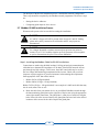
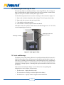
Connect the inverter’s Ethernet port to a hub or router. Ethernet cables must meet the
T-568B wiring standard and must be less than 300 feet in length.
•
Provide DHCP server access to the inverter. The inverter requires DHCP to establish
its IP address.
•
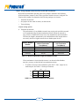
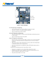
Provide a path to the Internet for https (port 443) from the inverter. The MAC address for the inverter can be found on the side of the communications PCB. To see the
MAC address the communications PCB must be removed from the card cage assembly.
•
Verify connectivity using the following information:
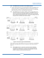
1. Check the status light. It should be in a solid on state.
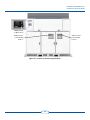
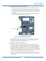
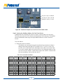
The status light is located on the front of the Comm X PCB in the right side of
the upper compartment in the Data Monitoring Section.
2. Verify the inverter’s MAC address has been assigned an IP address by the network.
3. Register the inverter at www.mypvpower.com.
Most connectivity problems relate to wiring issues or corporate security settings blocking
the inverter from accessing the Internet. Wiring problems are usually the result of a poor
crimp, wire that exceeds 320 ft., or pinched wires somewhere between the inverter and
the hub or router.
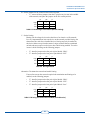
PV Powered recommends using pre-made cables whenever possible. If a cable must
be hand-crimped, we recommend testing the cable with a cable tester such as a Fluke
LinkRunner™ Pro Network Multimeter (LPRO1000). Verify the cable’s integrity by
connecting a laptop to the cable at the inverter and verify is has access to the Internet.
Corporate network problems will require support from your corporate IT department
where the inverter is installed. The most common problem is the inverter has not been
provided with DHCP server access using port 443.
Troubleshooting communications issues can also be accomplished using the four
LED lights on the communications PCB. For detailed LED communications light
troubleshooting see section 7.6 Communication PCB Status Light Operation.
Modbus via RS-485
For instructions on how to use the Modbus network option, refer to Chapter 5, Modbus
Network Installation.
46