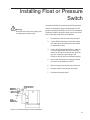
1
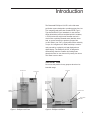
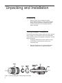
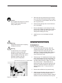
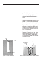
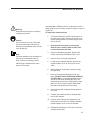
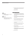
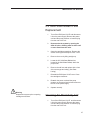
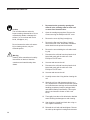
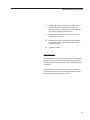
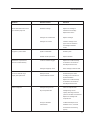
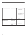
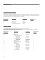
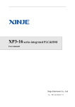
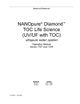
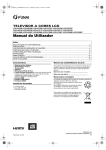
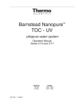
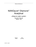
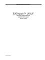
BARNSTEAD|THERMOLYNE CORPORATION
EASYpure™ UV/UF
OPERATION MANUAL
AND PARTS LIST
Series 1056
LT1056X2• 9/24/98
1
Table of Contents
Safety Information .............................................................................................................................................. 3
Alert Signals ....................................................................................................................................................... 3
Warnings ............................................................................................................................................................ 3
Introduction ........................................................................................................................................................ 5
General Use ....................................................................................................................................................... 5
General Specifications ....................................................................................................................................... 6
Dimensions and Clearance Requirements. ........................................................................................................ 6
Feedwater Requirements ................................................................................................................................... 6
Product Water .................................................................................................................................................... 6
Electrical Requirements ..................................................................................................................................... 7
Environmental Conditions .................................................................................................................................. 7
Declaration of Conformity ................................................................................................................................... 7
Installation .......................................................................................................................................................... 8
Unpacking and Installation ................................................................................................................................. 8
Tubing Adapter Installation ................................................................................................................................. 8
Ultrafilter and UV Lamp Installation .................................................................................................................... 9
Bench Mounting ............................................................................................................................................... 11
Wall Mounting (Optional) .................................................................................................................................. 12
Water Connections ........................................................................................................................................... 12
Controls ............................................................................................................................................................ 14
Main Power Switch ........................................................................................................................................... 14
Control Panel ................................................................................................................................................... 14
Switches ........................................................................................................................................................... 14
Display ............................................................................................................................................................. 15
Operational Modes ........................................................................................................................................... 16
Run Mode ......................................................................................................................................................... 16
Standby Mode .................................................................................................................................................. 16
Automatic Flush ............................................................................................................................................... 16
Initial Operation ................................................................................................................................................ 17
Initial Sanitization ............................................................................................................................................. 17
Cartridge Installation and Rinse Up ................................................................................................................. 18
Normal Operation ............................................................................................................................................. 20
Water Draw Off ................................................................................................................................................. 20
Use of Standby Modes ..................................................................................................................................... 20
Installing Float or Pressure Switch ................................................................................................................... 21
Maintenance and Servicing .............................................................................................................................. 22
System Sanitization and Cartridge Replacement ............................................................................................. 22
General Cleaning ............................................................................................................................................. 23
0.2 Micron Filter Replacement ......................................................................................................................... 23
Ultrafilter Replacement ..................................................................................................................................... 24
UV Lamp Replacement .................................................................................................................................... 24
Fuse Replacement ........................................................................................................................................... 26
UV Solid State Ballast Fuse Replacement ....................................................................................................... 27
Cleaning the Resistivity Cell ............................................................................................................................. 27
Shutdown ......................................................................................................................................................... 29
Troubleshooting ............................................................................................................................................... 30
Replacement Parts ........................................................................................................................................... 32
Wiring Diagrams ............................................................................................................................................... 35
Exploded Views ................................................................................................................................................ 38
Ordering Procedures ........................................................................................................................................ 40
Warranty ........................................................................................................................................................... 41
2
Safety Information
Alert Signals
Warning
Warnings alert you to a possibility of
personal injury.
Caution
Cautions alert you to a possibility of
damage to the equipment.
Note
Notes alert you to pertinent facts and
conditions.
Your Barnstead EASYpure™ UV/UF has been designed
with function, reliability, and safety in mind. It is your
responsibility to install it in conformance with local
electrical codes. This manual contains important operating and safety information. You must carefully read and
understand the contents of this manual prior to the use of
this equipment. For safe operation, please pay attention
to the alert indicators throughout this manual.
Water purification technology employs one or more of the
following: chemicals, electrical devices, mercury vapor
lamps, steam and heated vessels. Care should be taken
when installing, operating or servicing Barnstead products. The specific safety notes pertinent to this Barnstead
product are listed below.
Warnings
To avoid electrical shock, always:
1.
Use a properly grounded electrical outlet of
correct voltage and current handling capacity.
2.
Do not locate the EASYpure UV/UF directly
over equipment that requires electrical service. Routine maintenance of this unit may
involve water spillage and subsequent electrical shock hazard if improperly located.
3.
Replace fuses with those of the same type
and rating.
4.
Disconnect from the power supply prior to
maintenance and servicing.
To avoid personal injury:
1. Do not use in the presence of flammable or
combustible materials; fire or explosion may
result. This device contains components
which may ignite such materials.
3
SAFETY INFORMATION
2.
This device is to be used with water feeds only.
Sanitizing/cleaning agents must be used in
compliance with instructions in this manual.
Failure to comply with the above could result in
explosion and personal injury.
3.
Avoid splashing disinfecting solutions on clothing
or skin.
4.
Ensure all piping connections are tight to avoid
chemical leakage.
5.
Ensure adequate ventilation.
6.
Carefully follow manufacturer’s safety instructions on labels of chemical containers and
material safety data sheets.
7.
Depressurize system prior to opening cartridge
access door.
8.
This unit is equipped with an ultraviolet lamp.
Ultraviolet radiation may be harmful to the eyes
and skin. Do not attempt to observe the lamp
directly.
9.
A small amount of 2.0% hydrogen peroxide is
used to preserve the ultrafilter during storage.
When removing the ultrafilter from the bag,
ensure adequate ventilation and wear protective
gloves and glasses.
10. Refer servicing to qualified personnel.
4
Introduction
The Barnstead EASYpure UV/UF is a line-fed water
purification system designed to provide pyrogen-free, low
TOC reagent grade water that exceeds ASTM, Type I,
Type A and NCCLS Type I standards. It uses a threestage deionization process combined with UV oxidation,
a 10,000 molecular weight cutoff ultrafilter and a 0.2
micron filter to polish pretreated water (distilled, deionized, or reverse osmosis) to produce pyrogen-free
(<0.005 EU/ml), low TOC (<2 ppb) water with a resistivity
of up to 18.3 megohms-cm. Water resistivity is continuously sensed by a resistivity cell and displayed on a
digital display. The EASYpure UV/UF is designed to
automatically clean the ultrafilter by flushing water
through the filter for one minute every twenty-four hours.
This water is sent to drain.
General Use
Do not use this product for any purpose other than its
intended usage.
Drawoff Lever
Door Latch
Control Panel
Pump Interlock/
Pump Protector
Receptacle
Filter/Bell
Assembly
Main Power
Switch
Feedwater Inlet
Reject Water
Outlet
Power Cord
Receptacle
Figure 1: EASYpure UV Front
Figure 2: EASYpure UV Back
5
General Specifications
Dimensions and Clearance Requirements
EASYpure UV/UF dimensions: 12 " W X 19" D X 17 1/8" H (30.5 cm X 48.3 cm X 43.5 cm).
Clearances:
Sides: 4" (10.2 cm) minimum to allow air flow.
Above: 12" (30.5 cm) minimum for removal of the top cover.
Cartridge replacement requires that you be able to access the back of the unit and open the cartridge access
door (total depth, unit + open door, = 34" (86.4 cm)).
Electrical Requirements
The EASYpure UV/UF is equipped with a power cord to be plugged into an electrical outlet of the appropriate
voltage.
Model D8611 - 120 VAC ±5%, -10%, 47-63 Hz.
Model D8612 - 240 VAC ±5%, -10%, 47-63 Hz.
Model D8612-33 - 230 VAC ±10%, 47-63 Hz.
Model D8613 - 100 VAC ±5%, -10%, 47-63 Hz.
Feedwater Requirements
The EASYpure UV/UF requires water pretreated by either distillation, deionization or reverse osmosis meeting
the following criteria.
TOC: Less than 1.0 ppm.
Turbidity: 1.0 N.T.U. maximum
Temperature: 40°F - 120°F (4.4°C - 48.8°C)
Resistivity (Minimum):
Distilled - 300,000 Ohms
Deionized - 1.0 Megohms
Reverse osmosis - 50,000 Ohms
Product Water
Quality:
Resistivity: ASTM Type I
TOC: Less than 2.0 ppb
Endotoxin: Less than 0.005 EU/ML
Flow rate:1.5 LPM maximum at minimum inlet feedwater pressure of 30 PSIG at 60 HZ and with a new final
filter.
6
GENERAL SPECIFICATIONS
Environmental Conditions
Operating:
4°C - 49°C; 20% - 80% relative humidity,
non-condensing. Installation Category II
(over-voltage) in accordance with IEC 664.
Pollution Degree 2 in accordance with IEC
664. Altitude limit: 5,000 meters.
Storage: -25°C - 65°C; 20% to 80% relative humidity.
Declaration of Conformity
Barnstead|Thermolyne hereby declares under its sole
responsibility that this product conforms with the technical
requirements of the following standards (applies to -33
model(s) only):
EMC:
EN 50081-1
EN 50082-1
Generic Emission Standard;
Generic Immunity Standard.
Safety: IEC 1010-1-92 Safety requirements for electrical
equipment for measurement, control and laboratory use;
Part I: General Requirements
per the provisions of the Electromagnetic Compatability
Directive 89/336/EEC, as amended by 92/31/EEC and 93/
68/EEC, and per the provisions of the Low Voltage Directive
73/23/EEC, as amended by 93/68/EEC.
The authorized representative located within the European
Community is:
Electrothermal Engineering, Ltd.
419 Sutton Road
Southend On Sea
Essex SS2 5PH
United Kingdom
Copies of the Declaration of Conformity are available upon
request.
7
Unpacking and Installation
Unpacking
1.
Remove the unit from its shipping container.
Ensure that the ultrafilter, UV lamp, feed and reject
tubing, final filter, sanitization cartridge and power
cord are removed form the packaging materials
before discarding.
Tubing Adapter Installation
The following instructions will apply when you need to attach a
piece of tubing to your EASYpure UV/UF during installation,
unless otherwise noted in the installation instructions. To make
tubing connections:
1. Completely disassemble the fitting. Refer to Figure
3 to familiarize yourself with the names of the
component parts.
2.
Make sure the tubing is cut off reasonably square
and that no plastic burrs or ridges are present.
Figure 3: Typical Polypropylene Tubing Adapter Installation
8
INSTALLATION
Caution
Do not tighten tube fitting hex nut with a
wrench. Tight connections can be
easily made by hand.
Warning
Depressurize system prior to opening
cartridge access door.
Warning
A small amount of 2.0% hydrogen
peroxide is used to preserve the
ultrafilter during storage. When removing the ultrafilter from the bag, ensure
adequate ventilation and wear
protective gloves and glasses.
3.
Place the grab ring and back-up ring in the hex
nut in the order and orientation shown in Figure
3. Thread the nut onto the adapter. DO NOT use
the o-ring at this time.
4.
Push the tubing through the nut until it bottoms
out in the adapter.
5.
Remove the adapter nut and tubing. Place the
o-ring over the tubing. Be careful not to push the
back-up ring or grab ring further back on the
tubing when installing the o-ring.
6.
Install the hex nut on the adapter and hand
tighten.
Ultrafilter and UV Lamp
Installation
Install the ultrafilter as follows:
1. Remove the pump interlock plug. Open the
cartridge access door in the rear of the unit by
sliding the latch down and pulling the door
toward you. The door will swing down. Remove
the screws securing the EASYpure UV/UF’s
cover. Remove the cover.
2.
Disconnect tubing from this “T” to install ultrafilter
There are two “T’s” installed in the interior water
lines of the EASYpure UV/UF. One of these “T’s”
is connected to water lines which have identifying labels attached to them (“Reject” and “Product”). Remove this “T”. Ensure that the nut,
stainless-steel grab ring, backup ring and o-ring
from each connection remain on each piece of
tubing. Dispose of the “T” once you have removed it.
3.
Remove the ultrafilter from its protective bag.
4.
Identify the feed, product and reject connectors
on the ultrafilter. The feed connector is the
solitary one on one end of the ultrafilter. Hold the
ultrafilter so the feed connectors on the top face
Figure 4: “T” Removal
9
INSTALLATION
you. Viewed this way, the product connector is
the one on the left. The reject connector is the
one on the right. (See Figure 5) Remove the nut,
stainless steel grab-ring, backup ring and o-ring
from each of the ultrafilter connections and
discard.
5.
The three pieces of tubing that you disconnected
from the “T” in step 2 are the Feed, Reject and
Product lines for the ultrafilter. The Reject and
Product tubing nuts are labeled; the unlabeled
one is the Feed line. Connect the ultrafilter Feed,
Reject and Product lines to the appropriate
connectors on the ultrafilter, identified in step 4.
Ensure that the stainless-steel grab ring, backup
ring and o-ring from each connector remain on
each piece of tubing. Tighten the connectors by
hand; do not use a wrench.
6.
Press the ultrafilter into the ultrafilter securing
clips inside the EASYpure UV/UF case. Ensure
that you maintain the proper orientation of the
ultrafilter during installation, with the feed connection on the bottom and the reject and product
connections on the top.
Product
Reject
Black Plasitc Cap on
UV Chamber
Proper Installation of
Ultrafilter
Feed
Figure 5: Ultrafilter Connections
10
Figure 6: Ultrafilter Orientation and UV Chamber Location
INSTALLATION
Caution
Do not unscrew the cover, as this will
loosen the water tight seal and thus
damage the UV lamp.
Caution
Do not touch the glass portion of the
UV lamp. We recommend that you
wear lint-free gloves when handling the
lamp. The glass portion must be free of
fingerprints, perspiration, etc. Even a
single fingerprint will reduce the effectiveness of the lamp. If you accidentally
touch the glass portion of the lamp,
clean the lamp with a lint-free cloth; use
isopropyl alcohol if required.
Note
The UV lamp and receptacle fit together one way. If they do not readily
match holes to prongs, rotate the lamp
90° and try again.
7.
Locate the UV chamber. Carefully remove the
black plastic cover from the UV chamber by
pulling the cover straight up. Do not pull on
the cable.
8.
Remove the UV lamp from the packaging. Do
not touch the glass portion of the lamp!
9.
Clean the UV lamp with isopropyl alcohol and
a lint free cloth.
10. Carefully insert and hold the UV lamp partially
into the UV chamber.
11. Connect the UV lamp to the receptacle in the
black plastic cover of the UV chamber.
Replace the black plastic cover on the UV
chamber.
12. Replace the EASYpure UV/UF cover and
secure the cover with the screws removed in
step 1. Close the cartridge access door.
Replace the pump interlock plug. If you are
bench mounting the unit, go to Bench Mounting. If you are wall mounting the EASYpure
UV/UF, go to Wall Mounting .
Bench Mounting
1.
Warning
Do not locate the EASYpure UV/UF
directly over the equipment that
requires electrical service. Routine
maintenance of this unit may involve
water spillage and subsequent electrical shock hazard if improperly located.
Place the EASYpure UV/UF on a bench top
that is accessible to water, electricity and an
atmospherically vented drain, and that is
convenient to your work area, noting the
Clearance Requirements.
Do not use in the presence of flammable or combustible materials; fire or
explosion may result. The device
contains components which may ignite
such materials.
11
INSTALLATION
Wall Mounting (Optional)
Note
The outlet of a gravity feed storage
reservoir must be above or at the
same level as the inlet of the
EASYpure UV/UF.
Caution
Wall composition, condition and construction, as well as fastener type, must
be considered when mounting this unit.
The mounting surface and fasteners
selected must be capable of supporting
a minimum of 120 lbs. Inadequate
support and/or fasteners may result in
damage to mounting surface and/or
equipment. If you are unsure of mounting surface composition, condition and
construction or correct fasteners,
consult your building maintenance
group or contractor.
12
Install the optional wall bracket on the wall in a location that
is accessible to water, electricity and an atmospherically
vented drain, and that is convenient to use. A minimum of 4
fasteners must be used.
1. Remove the four feet from the EASYpure UV/UF
and retain the screws.
2.
Place the EASYpure UV/UF on the wall bracket
swivel base so the screw holes where the feet
were attached line up with the holes in the wall
bracket. There are guides on the wall bracket
that will mate with the EASYpure UV/UF. See
Figure 7.
3.
Reinstall the four screws removed in step 1
through the bottom of the wall bracket and into
the EASYpure UV/UF.
Water Connections
Feedwater Connection
1.
Locate the length of 3/8” O.D. tubing provided
with a quick disconnect insert on one end and a
3/8” O.D. X 1/4 NPT tubing adapter on the other.
2.
Install the tubing adapter onto your incoming
water line. We recommend a customer supplied
shut off valve be installed in your feed water line.
Do not connect the feedwater to your EASYpure
UV/UF until you are told to do so. (See Initial
Operation.)
INSTALLATION
Reject Water Connection
When the EASYpure UV/UF flushes its membrane, the
water used is sent to drain through this connection. To
install:
1. Locate the reject water tubing. This is the
piece of 1/4” O.D. tubing that has an adapter
on one end and no connector on the other
end. Remove the nut, grab ring, backup ring
and o-ring from the reject water fitting located
at the lower right of the unit. (See Figure 3 for
part identification and Figure 8 for fitting
location.)
Figure 7: Orientation of Swivel Base
2.
Follow instructions under Tubing Adapter
Installation and connect the reject water
tubing to the reject connection on the
EASYpure UV/UF.
3.
Route the other end of the reject water tubing
(the end with the adapter installed) to an
atmospherically vented drain. Ensure there
are no kinks in the tubing and that it proceeds
in a downward plane. If possible, use the
tubing adapter to permanently install the reject
water tubing in the drain.
Door Latch
Pump Interlock
Plug
Main Power
Switch
Power Entry
Module
Feedwater Inlet
Connection
Reject Water
Connection
Figure 8: EASYpure UV/UF Connections
13
Controls
Main Power Switch
The main power switch on the EASYpure UV/UF is located on
the back right of the unit (as you face the front of the unit),
directly above the power cord receptacle.
Control Panel
The EASYpure UV/UF is controlled through a control panel
which incorporates three switches, three indicating LED’s and
a digital display.
Switches
When the main power switch (on the back of the unit) is on,
the three switches on the control panel function as follows:
Start/Stop
When the unit is in the Off Mode, pressing
the START/STOP switch will put the unit in the run mode,
starting the pump and energizing the display. When the
EASYpure UV/UF is in the Standby Mode, pressing the
START/STOP switch will return the unit to run mode.
When the unit is in the run mode, pressing the START/STOP
switch will put the unit into the Off Mode.
Standby
Pressing the Standby switch will place the unit in Standby
Mode from either the Run Mode or the Off Mode. Pressing the
Standby switch while the unit is in Standby Mode has no
further effect.
Flush
Pressing the Flush switch once will initiate a one minute flush
of the ultrafilter. During this one minute flush, water is sent to
drain through the reject tubing, the Manual/Extended Flush
LED will be lit, and the display will be dark.
14
CONTROLS
Pressing the Flush switch twice will initiate a five minute
flush of the ultrafilter. During this five minute flush, water
is sent to drain through the reject tubing, the Manual/
Extended Flush LED will flash, and the display will be
dark. After the timed flush has ended, the EASYpure UV/
UF will return to the Mode (Off, Run or Standby) it was in
when you initiated the flush. We recommend that you
initiate a one minute manual flush when starting up the
EASYpure UV/UF prior to your day’s work.
Display
When the EASYpure UV/UF is in run mode, the display
indicates the purity (in megohms-cm) of the water
available for draw off. When the EASYpure UV/UF is in
Standby mode, the display will be dark and the Standby
LED will be lit. When the EASYpure UV/UF is in a Flush
mode, the display will be dark and the Manual/Extended
Flush LED will be either lit (indicating a one-minute flush)
or flashing (indicating a five-minute flush). During an
Automatic Flush, the Automatic Flush LED will be lit. If
the display indicates anything else, see the Troubleshooting section of this manual.
15
Operational Modes
Run Mode
Since not all qualities of permissible feedwater will reach
maximum resistivity after one pass through the unit’s
cartridges (especially as the cartridges near exhaustion),
the EASYpure UV/UF has two operational modes.
In the run mode, the UV lamp shines continuously and the
pump continuously recirculates water through the cartridges, the UV chamber and the ultrafilter. It is recommended that the EASYpure UV/UF be left in the run mode
during the day. In the run mode, the purity meter display
indicates the resistivity of the water available for draw off.
Standby Mode
Note
Do not turn off the EASYpure UV/UF
during non-work hours. Doing so will
allow bacterial growth and other
contamination of the water in the
system. As a result, the system will
require a lengthy rinse-up period at the
beginning of the work day to achieve
high-quality product water.
In Standby Mode, the UV lamp shines and the pump runs
for ten minutes out of every hour (i.e 10 minutes on, 50
minutes off). This will allow the unit to produce high quality
water quickly upon being placed in the run mode. It is
recommended that the EASYpure UV/UF be placed in the
Standby mode during non-work hours.
Automatic Flush
In both the run and Standby modes, the EASYpure UV/UF
will initiate a one minute automatic flush of the ultrafilter
once every twenty-four hours of operation. This prevents
bacterial buildup on the ultrafilter. A solid-state timer in the
EASYpure UV/UF counts the hours power is applied to the
unit. When the timer reaches twenty-four hours, the
EASYpure UV/UF initiates a one minute flush, the Automatic Flush LED is illuminated. The timer will reset to zero
when the one minute automatic flush is completed.
16
Initial Operation
Initial Sanitization
Warning
Avoid splashing disinfecting solutions
on clothing or skin.
Ensure all piping connections are tight
to avoid chemical leakage.
Ensure adequate ventilation.
Carefully follow manufacturer’s safety
instructions on labels of chemical
containers and material safety data
sheets.
This device is to be used with water
feeds only.
Sanitizing/cleaning agents must be
used in compliance with instructions in
this manual. Failure to comply with the
above could result in explosion and
personal injury.
Use of a properly grounded electrical
outlet of correct voltage and current
handling capacity.
Your EASYpure UV/UF has been shipped with a sanitization cartridge (Catalog Number D50245) and two empty
cartridges to allow you to sanitize your EASYpure UV/UF
prior to using it for the first time. To sanitize your
EASYpure UV/UF:
1. Open the cartridge access door. Install the
supplied D50245 sanitization cartridge in the
empty cartridge position. Press the upper end
cap into the upper right position until it bottoms
out. Then, lower the cartridge and insert the
lower end cap into the lower socket until it is
firmly seated. The empty cartridges have been
installed for you at the factory. Close and latch
the cartridge access door.
2.
Insert the quick disconnect insert on the
feedwater line into the feedwater inlet quick
disconnect on the back of the EASYpure UV/
UF.
3.
Plug the power cord into the unit’s power entry
module and plug into a live outlet. Place the
main power switch to the on position. Place a
suitable container under the outlet valve.
Depress the draw-off lever to open the outlet
valve. Press the “Flush” button twice to begin
an extended flush.
4.
Close the draw-off valve when solution exits
the system.
5.
When the extended flush stops (5 minutes),
open the draw-off valve. Press the START/
STOP button to start. Draw off 2.0 liters of
solution through the draw-off valve. Close the
draw-off valve. Discard the solution.
6.
Recirculate the disinfectant solution for
approximately 30-45 minutes.
7.
Press the START/STOP button to stop.
Sanitization Cartridge
D50245
Empty Cartridges
Figure 9: Preparing To Sanitize
17
INITIAL OPERATION
Warning
Depressurize system prior to
opening cartridge access door.
Note
If the EASYpure UV/UF is wall
mounted, rotate the EASYpure UV/UF
until the cartridge access door faces
forward and the EASYpure UV/UF
locks into place.
The EASYpure UV/UF’s cartridges
must be installed in the proper order.
If you have just sanitized your
EASYpure UV/UF, retain the empty
cartridges shipped with your unit for
use when you sanitize it in the future,
discard the D50245 sanitization
cartridge.
The cartridges will still contain water
when removed. Therefore, you will
want to have a sink, bucket or other
waterproof container available to place
them in after removal.
The upper end cap is the one with the
right-angle turn and the two flanges.
The lower end cap extends straight
out from the cartridge.
The two flanges on the end cap
should be able to slide down on each
side of the keyway wall.
18
8.
Open the draw-off valve to depressurize the
system. Leave valve open until solution
completely stops flowing, draining as much
of the system as possible.
9.
Proceed to Cartridge Installation and Rinse Up.
Cartridge Installation and Rinse
Up (Refer to Figure 10)
1.
Open cartridge access door in the rear of the unit
by pushing the door latch down.
2.
Remove the cartridge in the right-hand cartridge
position by pulling t first up and then out. Used
cartridges can be recycled; see the P.U.R.E.
information packed with your new cartridges.
3.
Remove a new Pretreatment cartridge (Catalog
No. D50230) from its plastic bag.
4.
Wet the o-rings on both end caps.
5.
Press the upper end cap into the upper right
position until it bottoms out.
6.
Lower the cartridge and insert the lower end cap
into the lower socket until it is firmly seated.
7.
Repeat steps 2 - 6 with the EASYpure
ULTRApure (Catalog No. D50233) cartridge,
placing it in the center position. Do not install the
High Purity/Low TOC (Catalog No. D50229)
cartridge or the 0.2 micron filter and bell assembly at this time.
8.
Close cartridge access door.
9.
Place a suitable container under the outlet valve.
Depress the draw-off lever to open the draw-off
valve.
INITIAL OPERATION
Pretreatment Cartridge
D50230
10. Press the “Flush” button twice to begin an
extended flush. When water begins exiting the
system, close the draw-off valve.
11. When the extended flush ends, press the
START/STOP button to stop and depressurULTRApure Cartridge
ize the system by opening the draw-off
D50233
valve and allowing water to drain from the
unit until draining ceases. Close the drawoff valve. Open the cartridge access door and
repeat steps 2 - 6 with the EASYpure High
Purity/Low TOC (Catalog No. D50229)
cartridge, placing it in the left-hand position.
Do not install the 0.2 micron filter and bell
assembly at this time.
High Purity/Low TOC Cartridge
D50229
Figure 10: Proper Cartridge Position and Order
Warning
Use properly grounded electrical outlet
of correct voltage and current handling
capacity.
12. Close the cartridge access door. Press the
“Flush” button twice again to begin another
extended flush. When the extended flush
ends, open the draw-off valve and press the
START/STOP button. Rinse 10-15 liters of
water through the draw-off valve to drain.
Close the draw-off valve.
13. Remove a new 0.2 micron filter and bell
assembly from its bag and insert it into the
Luer fitting on the draw-off valve. Gently turn it
clockwise until it is fully seated in the Luer
fitting.
14. Remove the protective cap from the filter bell.
Open the draw-off valve and flush 10-15 liters
of water through the 0.2 micron filter.
Caution
Do not allow EASYpure UV/UF to
operate unless water is available to
unit.
Note
For more demanding applications
where low TOC water is required, a
rinse of 15-20 liters through the cartridges and filter may be necessary.
19
Normal Operation
Note
On initial start-up, the purity meter may
display “ERR”. This is caused by air in
the cell and should be replaced by a
resistivity reading almost immediately.
If “ERR” does not go out after the
pump has run for a minute or if it
appears any time while the EASYpure
UV/UF is in operation, refer to the
Problem Solving section of this
manual.
Note
For low organic and pyrogen applications, draw off 50 to 100 ml of water
from system and discard prior to
drawing water for each use.
Note
Do not turn off the EASYpure UV/UF
during non-work hours. Doing so will
allow bacterial growth and other
contamination of the water in the
system. As a result, the system will
require a lengthy rinse-up period at the
beginning of the work day to achieve
high-quality product water.
20
1.
Press the START/STOP button to start. The
EASYpure UV/UF’s pump will begin to run and
the Purity meter will display the resistivity of the
water in megohm-cm.
2.
Allow the water’s resistivity to rise to the desired
purity before drawing off water.
3.
The system should be left on during the work
day. (See use of Standby mode.)
Water Draw Off
1.
Remove the protective cap from the filter bell.
2.
Depress the draw-off lever.
3.
When draw off is complete, lift the draw-off lever
and replace the protective cap on the filter bell.
Use of Standby Mode
At the end of the work day, press the Standby switch on the
front of the EASYpure UV/UF to place the unit in Standby
mode for the night.
Installing Float or Pressure
Switch
Warning
Disconnect from the power supply prior
to maintenance and servicing.
Accessories D0606 (float switch) and D2706 (pressure
switch) are designed to protect the EASYpure UV/UF
pump by alerting the EASYpure UV/UF of an inadequate
feedwater condition so that the pump can be shut down.
Use the following instructions for installation.
1.
Disconnect the unit from the electrical power.
2.
If using D0606 float switch, follow the installation instructions included with the float switch
for installation to tank.
3.
If using D2706 low pressure switch, install the
PVC tee (supplied with D2706) in incoming
water line. Screw the switch into the top of the
tee, then connect the inlet tubing to the
EASYpure UV/UF with the remaining opening.
4.
Route cable from float or low pressure switch
to the rear of the EASYpure UV/UF.
5.
Remove jumper plug and save for future use.
6.
Plug the cable into the jumper plug outlet.
7.
Reconnect electrical power.
Figure 11: Float and Pressure Switch Installation
21
Maintenance and Servicing
System Sanitization and Cartridge
Replacement
The frequency with which you will need to clean your unit and
replace cartridges is dependent on your feedwater’s characteristics, your purity requirements and your usage. Sanitize
your EASYpure UV/UF and replace the cartridges when the
product water purity drops below acceptable levels of resistivity, when organic levels become too high, or if a new 0.2
micron filter was installed. To sanitize the EASYpure UV/UF,
Note
the purification cartridges must be replaced with a sanitization
The cartridges will still contain water
cartridge and the two empty cartridges supplied with your unit.
when removed. Therefore, you will
The simple-to-use sanitization cartridge is available from
want to have a sink, bucket or other
Barnstead|Thermolyne (Catalog No. D50245). This is used in
waterproof container available to place addition to the empty cartridges included with this unit to effect
them in after removal.
a complete sanitization.
Warning
Disconnect from the power supply prior
to maintenance and servicing. Refer
servicing to qualified personnel.
Warning
Depressurize system prior to opening
cartridge access door.
Note
If the EASYpure UV/UF is wall
mounted, remove the power cord and
rotate the EASYpure UV/UF until the
cartridge access door faces forward
and the EASYpure UV/UF locks into
place.
Note
The two flanges on the end cap should
be able to slide down on each side of
the keyway wall.
22
1.
Turn unit off.
2.
Disconnect the unit from the power supply. Disconnect the unit from the water supply.
3.
Depressurize system by opening the draw-off
valve.
4.
Open the cartridge access door in the rear of the
unit by sliding the latch down and pulling the door
toward you. The door will swing down.
5.
Remove the exhausted cartridge in the right-hand
position by pulling it first up and then out. Used
cartridges can be recycled; see the P.U.R.E.
information packed with your new cartridges.
6.
Remove a D50245 sanitization cartridge from its
packaging. Press the upper end of the D50245
sanitization cartridge into the upper right position
until it bottoms out.
7.
Lower the cartridge and insert the lower end cap
into the lower socket until it is firmly seated.
MAINTENANCE AND SERVICING
Note
Used cartridges may be recycled. See
P.U.R.E. information packed with new
cartridges.
8.
Repeat steps 2 - 6 with the two empty cartridges supplied with your EASYpure UV/UF,
placing them in the center and left-hand
positions.
9.
Close the cartridge access door. Remove the
0.2 micron filter and bell assembly.
10. Sanitize, install new cartridges and rinse
according to the instructions for Initial Sanitization and Cartridge Installation in the Initial
Operation section.
General Cleaning Instructions
Wipe exterior surfaces with lightly dampened cloth
containing mild soap solution.
0.2 Micron Filter Replacement
Caution
Do not overtighten the 0.2 micron filter
assembly onto the Luer fitting or use
excessive force in seating it. The filter
and/or Luer fitting can be damaged by
overtightening or excessive force.
Note
If a newly installed 0.2 micron filter
clogs rapidly after installation, the
EASYpure UV/UF may need to be
sanitized to remove bacterial contaminants. See System Sanitization.
Replace the 0.2 micron filter whenever any of the following conditions occur: every 30 days, the product water
flow rate is reduced or bacteria break through. The 0.2
micron filter is shipped assembled with a bell. To replace
the 0.2 micron filter assembly:
1.
Remove the old 0.2 micron filter assembly by
turning it counterclockwise until it is free from
the Luer fitting.
2.
Remove the new 0.2 micron filter assembly
from its bag and insert it into the Luer fitting.
Gently turn it clockwise until it is fully seated in
the Luer fitting.
3.
Rinse 10-15 liters of water through the filter to
drain prior to using the product water.
23
MAINTENANCE AND SERVICING
Ultrafilter Replacement
The length of your ultrafilter’s life will depend to some
extent on conditions and use in your lab. When you are
unable to completely sanitize your system (i.e. you can no
longer get pyrogen-free water even after sanitizing the
system), replace the ultrafilter as follows:
1.
Turn off the EASYpure UV/UF and disconnect it
from the power supply.
Note
Some water will drain from the ultrafilter when you disconnect it. Have a
container ready to hold the ultrafilter
and catch the water while it drains.
Water will also drain from the tubing of
the EASYpure UV/UF onto your bench
or floor. To avoid slipping and falling,
clean up all spills.
2.
Depressurize the system by opening the draw-off
valve, allowing water to drain until no more water
flows from the valve.
3.
Follow the instructions for ultrafilter installation
found under Ultrafilter Installation, removing the old
ultrafilter in the same way that the instructions
describe removing the “T”.
4.
Sanitize the EASYpure UV/UF according to the
instructions on page 24.
UV Lamp Replacement
Warning
Depressurize system prior to opening
cartridge access door.
Warning
This unit is equipped with an ultraviolet
lamp. Ultraviolet radiation is harmful to
the eyes and skin. Do not attempt to
observe the lamp directly.
Note
The UV Solid State Ballast in the
EASYpure UV/UF cabinet has a green
light that will be lit if the lamp is illuminated. Also, an audible sound will alert
you if the lamp is not lit or is
disconnected.
24
The ultraviolet lamp requires changing every 90-120 days.
Lamp life will vary according to the number of times the
EASYpure UV/UF unit is turned on and off ( the START/
STOP mode). This estimated lamp life is based on the
EASYpure UV/UF being operated in the RUN mode during
normal working hours (assumed to be 9 hours/day, 5 days/
week) and then placed in the STANDBY mode during off
hours (15 hours/day), weekends and holidays. Since the
lamp turns on 10 minutes/hour during the STANDBY mode,
this amounts to 15 START/STOP cycles per working day. If
the EASYpure UV/UF is cycled between the RUN and
STANDBY modes during the work day, this will result in a
shorter lamp life. Therefore, it is recommended that the
EASYpure UV/UF be left in the RUN position during normal
working hours. Leaving the unit in the STOP mode at night
and on weekends will lengthen UV bulb life but will compromise water quality. Higher rates of bacterial growth, as well
as ionic and organic purity degradation, will occur,
MAINTENANCE AND SERVICING
Warning
Depressurize system prior to opening
cartridge access door.
Caution
Do not unscrew the cover, as this will
loosen the water tight seal and may
damage the replacement lamp. Pull the
cover straight up.
Note
Pay close attention to the orientation of
the plug as it is attached to the UV
lamp. It will be necessary to ensure
that the plug is installed in the same
manner as removed.
necessitating the EASYpure UV/UF be placed in a recirculating mode for up to one hour to achieve organic content of
2 ppb TOC.
To replace the ultraviolet lamp:
1.
Turn off the EASYpure UV/UF and disconnect it
from the power supply. Remove the power cord
and the pump protector or interlock plug from the
rear or the unit.
2.
Depressurize the system by opening the
draw-off valve, allowing water to drain until
no more flows from the valve.
3.
Open the cartridge access door. Remove the
screws securing the EASYpure UV/UF cover.
4.
Remove the cover by lifting straight up.
5.
Locate the UV oxidation chamber and pull the
top black plastic cover off. Do not pull on the
cable.
6.
While holding on to the lamp, remove the plug
from the lamp.
7.
Remove the replacement lamp from its container. DO NOT TOUCH THE GLASS PORTION
OF THE LAMP. It is recommended that lint free
gloves be worn when handling the lamp. The
glass portion must be free of fingerprints, perspiration, etc. Even a light coating of perspiration
will reduce the effectiveness of the lamp.
8.
Clean the lamp with isopropyl alcohol and a lint
free cloth.
9.
Carefully insert and hold the UV lamp partially
into the UV chamber.
10. Connect the UV lamp to the receptacle in the
black plastic cover of the UV chamber. Replace
the black plastic cover on the UV chamber.
11. Reinstall the EASYpure UV/UF cover. Close the
cartridge access door.
25
MAINTENANCE AND SERVICING
12. Reattach the power cord and the pump protector
or the pump interlock and reconnect the unit to
the power supply.
13. Operate normally.
Fuse Replacement
Warning
1.
Turn off the EASYpure UV/UF and disconnect it
from the power supply. Remove the power cord
and the pump protector or interlock plug from the
rear of the unit.
2.
Depressurize the system by opening the draw-off
valve, allowing water to drain until no more flows
from the valve.
3.
Open the cartridge access door. Remove the
screws securing the EASYpure UV/UF cover.
4.
Remove the cover by lifting straight up.
5.
Pull out the fuse drawer located in the power
entry module.
6.
Remove old fuses and replace with fuses of the
same type and rating. (See Parts Listing.)
7.
Replace fuse drawer.
8.
Reinstall the EASYpure UV/UF cover. Close the
cartridge access door.
9.
Reattach the power cord and the pump protector
or the pump interlock and reconnect the unit to
the power supply.
Depressurize system prior to opening
cartridge access door.
Warning
Replace fuses with those of the same
type and rating. Fuse Type 5 x 20 mm,
Time Lag (T) 250V 1.0 Amp.
10. Operate normally.
26
MAINTENANCE AND SERVICING
UV Solid State Ballast Fuse
Replacement
Warning
Depressurize system prior to opening
cartridge access door.
1.
Turn off the EASYpure UV/UF and disconnect
it from the power supply. Remove the power
cord and the pump protector or interlock plug
from the rear of the unit.
2.
Depressurize the system by opening the
draw-off valve, allowing water to drain until
no more flows from the valve.
3.
Open the cartridge access door. Remove the
screws securing the EASYpure UV/UF cover.
4.
Remove the cover by lifting straight up.
5.
Locate the UV Solid State Ballast fuse,
located in the Solid State Ballast, above the
pump motor.
6.
Remove the old fuse and replace with a fuse
of the same type and rating. (See Parts
Listing.)
7.
Reinstall the EASYpure UV/UF cover. Close
the cartridge access door.
8.
Reattach the power cord and the pump
protector or the pump interlock and reconnect
the unit to the power supply.
9.
Operate normally.
Cleaning the Resistivity Cell
1.
Turn off the EASYpure UV/UF and disconnect
it from the power supply. Remove the power
cord and the pump protector or interlock plug
from the rear of the unit.
27
MAINTENANCE AND SERVICING
Caution
The cell electrodes are etched to
improve wetting characteristics. Do not
mechanically abrade or damage this
surface (i.e. do not clean with a wire
brush, sandpaper, etc.).
Do not immerse the entire cell assembly in cleaning solution, only the
electrode portion.
Warning
Carefully follow manufacturer’s safety
instructions on labels of chemical
containers and material safety data
sheets.
2.
Depressurize the system by opening the
draw-off valve, allowing water to drain until
no more flows from the valve.
3.
Open the cartridge access door. Remove the
screws securing the EASYpure UV/UF cover.
4.
Remove the cover by lifting it straight up.
5.
Remove the filter and Luer fitting. Carefully
remove the front cover. Disconnect membrane
switch lead from the printed circuit board.
6.
Remove the screw holding the cell-cable retaining clip.
7.
Disconnect the cell lead from the printed circuit
board and gently pull the cable out of the
EASYpure UV/UF frame.
8.
Unscrew and remove the cell.
9.
Disconnect the cell lead from the printed circuit
board and gently pull the cable out of the
EASYpure UV/UF frame.
10. Unscrew and remove the cell.
11. Carefully remove the O-ring before cleaning the
cell.
12. Wash the cell in a mild detergent solution or a
10% Hydrochloric or Sulfuric acid solution (follow
acid manufacturers warnings and recommended
handling procedures found on package labels
and Material Safety Data Sheets). This may be
done in an ultrasonic cleaner or with a soft
brush.
13. Thoroughly rinse the cell in deionized or distilled
water following the detergent or acid cleaning.
14. After cleaning, reinstall and check the o-ring on
cell; replace if necessary.
15. Reinstall the cell well and hand tighten. Reroute
the cable up through the housing and reconnect.
28
MAINTENANCE AND SERVICING
16. Reinstall the screw holding the cell-cable retaining clip. Reinstall membrane switch lead. Replace the front cover. Replace the Luer fitting with
new Teflon® tape and reinstall fitting.
17. Reinstall the EASYpure UV/UF cover. Close the
cartridge access door.
18. Reattach the power cord and the pump protector
or the pump interlock and reconnect the unit to
the power supply.
19
Operate normally.
Shutdown
If the EASYpure UV/UF is to be shut down for an extended
period of time, the unit should be completely drained and
the cartridges and ultrafilter removed to prevent the growth
of bacteria.
If the system has remained inactive and full of water for
more than 96 hours, the unit should be drained, sanitized
and new cartridges installed prior to use.
29
Troubleshooting
Problem
Possible Causes
Solutions
EASYpure UV/UF completely
No electrical power to
Ensure that the EASYpure
inactive. (Pump not operating,
EASYpure UV/UF.
UV/UF power cord is
control panel not lit, etc.)
connected to a live power
source and completely
plugged into electrical outlet.
Membrane Switch leads not
Disconnect unit from power.
connected.
Check and reconnect.
Main Power Switch off.
Place to On Position.
Connector from Main PCB to
Disconnect unit from power.
Display PCB not connected.
Check and reconnect.
Fuses blown.
Replace the fuses as
indicated in the Fuse
Replacement section.
Pump runs, but no display (no
Resistivity Monitor PCB and
Disconnect unit from power.
digital display).
Display PCB not connected.
Check and reconnect boards.
Pump does not run. Display lit.
Low water in feedwater tank or
Replenish feedwater. Check
low inlet water pressure.
inlet water line for
constrictions, blockages or
closed valves.
Jumper or devices not installed
Install.
in pump interlock.
Pump worn out or defective.
Replace pump.
Display reads “Err” when
Resistivity cell lead
Check resistivity cell lead.
checking resistivity.
disconnected.
Air in system.
Purge air from system by
drawing off water according to
the instructions in the
Operation section.
30
Resistivity cell defective.
Replace resistivity cell.
Resistivity cell dirty.
Clean cell and reinstall.
TROUBLESHOOTING
Problem
Possible Causes
Solutions
Recirculated water will not rinse
Exhausted cartridge
Replace the cartridge as
up to desired purity level.
indicated in the Cartridge
Replacement section.
Cartridges are contaminated.
Replace cartridges.
Cartridges out of order.
Install the cartridges in the
proper order as indicated in
the Cartridge Installation
section.
Pyrogens in product water.
Reduced or no product flow
System contaminated.
Sanitize system.
Ultrafilter needs replacement.
Replace Ultrafilter.
0.2 micron final filter clogged.
Replace the 0.2 filter assembly
from the 0.2 filter assembly.
as indicated in the 0.2 Micron
Filter Replacement section.
Cartridges improperly rinsed.
Rinse cartridges; install new filter.
0.2 micron final filter clogs
EASYpure UV/UF
Sanitize EASYpure UV/UF
rapidly after replacement.
contaminated with bacteria.
according to the instructions in
System Sanitization.
Replace the 0.2 filter assembly
as indicated in the 0.2 Micron
Filter Replacement section.
Short cartridge life.
Cartridges being used are
beyond expiration date.
Check the expiration date.
Cartridges begin to lose
capacity after being stored two
years from the date of manufacture.
Replace the cartridges with
unexpired ones.
Change in feedwater
If a Barnstead ROpure is the
characteristics.
feedwater source, check that
the membrane is functioning
properly.
31
TROUBLESHOOTING
Problem
Possible Causes
Solutions
If a Barnstead Still is the
Short cartridge life (cont.)
feedwater source, ensure that the
membrane is functioning properly.
If feedwater is from a central
water purification system, verify
water quality and proper
functioning of the system.
Water leakage inside
Loose connections.
Tighten connections.
Missing or defective cartridge
Install or replace cartridge
O-rings.
O-rings.
Green light on UV Solid State
UV lamp not plugged into
Plug UV lamp into UV Ballast.
Ballast not lit and audible alarm
UV Solid State Ballast.
EASYpure UV/UF.
sounds.
UV lamp burnt out.
Replace UV lamp.
UV lamp not connected to
Recheck/reconnect.
connector or improper
connection.
32
Replacement Parts
Consumables
Consumable parts are those required to support the day-to-day operation of this equipment.
Barnstead|Thermolyne establishes two types of consumables; those items that must periodically be replaced to
maintain performance (filters, resin cartridges, etc.) and other items of limited life (indicator lights, fuses, etc.)
that you can expect to replace on a more or less random basis. Where practical, Barnstead|Thermolyne
recommends the frequency of replacement, or provides information on life expectancy from which you may
calculate a replacement interval compatible with your usage pattern.
The replacement of consumable parts is discussed in the MAINTENANCE AND SERVICING section to assist
you in accomplishing your own service.Consumables may be ordered separately and in some cases, as an
expendables kit. Check with your Barnstead|Thermolyne representative for additional information on the
expendables kit.
Exploded View
Key Number
Not Shown
Not Shown
Not Shown
Not Shown
1
Not Shown
Not Shown
2
Not Shown
Not Shown
Description
Pretreatment Cartridge DI Feed
EASYpure High Purity/Low TOC Cartridge
Ultrapure Mixed Bed Cartridge
0.2 Micron Filter and Bell Assembly
Fuse, Power Entry
100-120 Volt
230 Volt (5X20mm, Time Lag (T),
250V, 1.0 Amps)
240 Volt
Empty Cartridges for sanitization (set of 2)
O-rings, cartridges
Ultraviolet lamp
Fuse - Solid State Ballast
Ultrafilter
Catalog No.
Recommended
Quantity
D50230
D50229
D50233
FL703X2
1
1
1
2
04455
2
5120-0025
FZX37
D7034
06162
LMX13
FZX47
FL550X1
2
2
1
12
1
1
1
33
REPLACEMENT PARTS
General Maintenance
General maintenance parts are defined as laboratory level repair parts which do not require great expertise or
special tools for installation. Barnstead|Thermolyne recommends that you stock the general maintenance parts
as an aid to ensuring the continued operation of this equipment.
Exploded View
Key Number
Description
Catalog No.
Recommended
Quantity
3
4
5
Check Valve
Luer Fitting
Pressure Regulating Valve
02214
PM703X3
02280
1
1
1
Safety Stock
For critical applications where performance with minimum downtime is required,
Barnstead|Thermolyne recommends that you maintain a local stock of those parts listed in the GENERAL
MAINTENANCE PARTS and SAFETY STOCK sections.
Exploded View
Key Number
Description
Catalog No.
Recommended
Quantity
6
7
Display PCB
Resistivity Monitor PCB
100-120 Volt
230-240 Volt
Pump and Motor Ass’y.
100-120 Volt
230-240 Volt
Resistivity Cell
Draw-Off Valve Ass’y.
Main PCB
Solenoid Valve
100-120 Volt
230-240 Volt
UV Power Supply
100V & 120V
230-240V
Solid State Ballast
PC741X1A
1
PC741X2
PC741X4
1
1
PU1056X2A
PU1056X1A
E703X1A
PM741X1A
PC741X3A
1
1
1
1
1
RY631X1A
RY631X3A
1
1
1
1
1
1
8
9
10
11
12
13
14
34
PC733X1B
PC733X3A
PC733X2
GROUND
LINE
RETURN
POWER
CORD
1
3.0 A
3.0 A
BLACK
WHITE
RED
2
3
MOTOR
4
RED
BLACK
PUMP INTERLOCK
WITH JUMPER PLUG
FOR USE WITH
OPTIONAL PRESSURE
OR FLOAT SWITCH.
1
REJECT/FLUSH
SOLENOID
YELLOW
PUMP
FEEDWATER
SOLENOID
BLUE
POWER ENTRY MODULE
WITH LINE FILTER
DPST SWITCH AND
FUSE DRAW
ORANGE
LINE
FILTER
PROD
FEED
PUMP
PUMP
FEED
PROD
GND
L1
L2
NANO
NANO
J1
4
BLACK
P2
PCB
Easypure U.F.
1
2
3
-
+
SUPPLY
PCB
POWER
U.V.
YELLOW
GREEN
ORANGE
BLACK
RED
SOLID
STATE
PCB
BALLAST
LAMP
U.V.
SWITCH
DISPLAY PCB'S
MEMBRANE
MONITOR AND
P3
EASYPURE U.F.
RESISTIVITY
CELL
2
4
CAT. NO. D0603
OPTIONAL FLOAT
SWITCH
2
3
CAT. NO. D2706
SWITCH
OPTIONAL PRESSURE
CR
1
3
4
Wiring Diagrams
100 Volt Wiring Schematic
35
TRANSFORMER
100/120 VAC
100 VAC, 50/60 Hz
120 VAC, 50/60 Hz
GROUND
LINE
RETURN
POWER
CORD
1
3.0 A
3.0 A
POWER ENTRY MODULE
WITH LINE FILTER
DPST SWITCH AND
FUSE DRAW
LINE
FILTER
36
3
2
4
MOTOR
RED
BLACK
PUMP INTERLOCK
WITH JUMPER PLUG
FOR USE WITH
OPTIONAL PRESSURE
OR FLOAT SWITCH.
1
REJECT/FLUSH
SOLENOID
YELLOW
PUMP
FEEDWATER
SOLENOID
BLUE
120 Volt Wiring Schematic
ORANGE
PROD
FEED
PUMP
PUMP
FEED
PROD
GND
L1
L2
NANO
NANO
J1
PCB
Easypure U.F.
DISPLAY PCB'S
RESISTIVITY
MONITOR AND
EASYPURE U.F.
CELL
4
1
2
3
BLACK
ORANGE
+
-
SUPPLY
PCB
U.V.
POWER
YELLOW
GREEN
P2
BLACK
RED
P3
BALLAST
PCB
SOLID
STATE
U.V.
LAMP
SWITCH
MEMBRANE
CR
1
4
3
3
OPTIONAL PRESSURE
SWITCH
CAT. NO. D2706
2
OPTIONAL FLOAT
SWITCH
CAT. NO. D0603
2
4
WIRING DIAGRAMS
240 VAC, 50/60 Hz
GROUND
LINE
RETURN
CORD
POWER
2.0 A
2.0 A
POWER ENTRY MODULE
WITH LINE FILTER
DPST SWITCH AND
FUSE DRAW
2
3
4
MOTOR
PUMP
RED
BLUE
BLACK
PUMP INTERLOCK
WITH JUMPER PLUG
FOR USE WITH
OPTIONAL PRESSURE
OR FLOAT SWITCH.
1
REJECT/FLUSH
SOLENOID
FEEDWATER
SOLENOID
YELLOW
LINE
FILTER
230 - 240 Volt Wiring Schematic
ORANGE
PROD
FEED
PUMP
PUMP
FEED
PROD
GND
L1
L2
NANO
NANO
J1
PCB
Easypure U.F.
DISPLAY PCB'S
RESISTIVITY
MONITOR AND
EASYPURE U.F.
CELL
1
2
3
4
U.V.
-
+
PCB
POWER
SUPPLY
YELLOW
ORANGE
GREEN
BLACK
P2
BLACK
RED
P3
BALLAST
PCB
SOLID
STATE
U.V.
LAMP
MEMBRANE
SWITCH
CR
1
4
CAT. NO. D2706
OPTIONAL PRESSURE
SWITCH
2
CAT. NO. D0606
SWITCH
OPTIONAL FLOAT
2
3
3
4
WIRING DIAGRAMS
37
Exploded Views
38
EXPLODED VIEWS
39
Ordering Procedures
Please refer to the Specification Plate for the complete model number, serial number, and series number when
requesting service, replacement parts or in any correspondence concerning this unit.
All parts listed herein may be ordered from the Barnstead Thermolyne dealer from whom you purchased this
unit or can be obtained promptly from the factory. When service or replacement parts are needed we ask that
you check first with your dealer. If the dealer cannot handle your request, then contact our Customer Service
Department at 319-556-2241 or 800-553-0039.
Prior to returning any materials to Barnstead Thermolyne Corp., please contact our Customer Service
Department for a “Return Goods Authorization” number (RGA). Material Returned without an RGA number will
be returned.
40
One Year Limited Warranty
Barnstead|Thermolyne Corporation warrants that if a product manufactured by Barnstead|Thermolyne and
sold by it within the continental United States or Canada proves to be defective in material or construction, it
will provide you, without charge, for a period of ninety (90) days, the labor, and a period of one (1) year, the
parts, necessary to remedy any such defect. Outside the continental United States and Canada, the warranty
provides, for one (1) year, the parts necessary to remedy any such defect. The warranty period shall
commence either six (6) months following the date the product is sold by Barnstead|Thermolyne or on the
date it is purchased by the original retail consumer, whichever date occurs first.
All warranty inspections and repairs must be performed by and parts obtained from an authorized
Barnstead|Thermolyne dealer or Barnstead|Thermolyne (at its own discretion). Heating elements, however,
because of their susceptibility to overheating and contamination, must be returned to our factory, and if, upon
inspection, it is concluded that failure is not due to excessive high temperature or contamination, warranty
replacement will be provided by Barnstead|Thermolyne. The name of the authorized Barnstead|Thermolyne
dealer nearest you may be obtained by calling 1-800-446-6060 (319-556-2241) or writing to:
Barnstead|Thermolyne
P.O. Box 797
2555 Kerper Boulevard
Dubuque, IA 52004-0797
USA
FAX: (319) 589-0516
E-MAIL ADDRESS: [email protected]
Barnstead|Thermolyne’s sole obligation with respect to its product shall be to repair or (at its own discretion)
replace the product. Under no circumstances shall it be liable for incidental or consequential damage.
THE WARRANTY STATED HEREIN IS THE SOLE WARRANTY APPLICABLE TO Barnstead|Thermolyne
PRODUCTS. Barnstead|Thermolyne EXPRESSLY DISCLAIMS ANY AND ALL OTHER WARRANTIES,
EXPRESSED OR IMPLIED, INCLUDING WARRANTIES OF MERCHANTABILITY OR FITNESS FOR USE.
41
42
43
Barnstead|Thermolyne
2555 Kerper Blvd.
P.O. Box 797
Dubuque, IA 52004-2241
Phone: 319-556-2241 800-553-0039
Fax: 319-589-0516
E-Mail Address: [email protected]
44
ISO
9001
REGISTERED