1
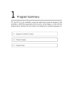
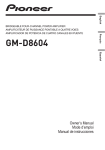
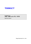
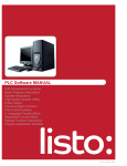
XCC Series PLC User Manual XINJE Electronic Co.Ltd. Number: PC02 20100825 3.2 Xinje Electronic Table of Contents Preface XCC ———————————————————— Series PLC XCC Series PLC Summary 1 ———————————————————— User Manual Power Supply Circuit Specification, 2 I/O Specification and External Wiring ———————————————————— Soft Components, HSC, External 3 Input, Interruption ———————————————————— 4 Instruction List Appendix ———————————————————— The first Version Number: PC02 20100825 3.2 This manual includes some basic precautions which you should follow to keep you safe and protect the products. These precautions are underlined with warning triangles in the manual. About other manuals that we do not mention, please follow basic electric operating rules. Precautions Correct Application Please follow the precautions. If not, it may lead the controlsystem incorrect or abnormal, even cause fortune lose. The models could only be used according to the manual, and an only be used along with the peripheral equipments recognized or recommended by Xinje Electronic. They could only work normally in the condition of be transported, kept and installed correctly, also please operate and maintain them according to the recommendation. Xinje Electronic Co., Ltd. Copyright reserved Without exact paper file allowance, copy, translate or using the manual is not allowed. Disobey this, people should take the responsibility of loss. We reserve all the right of expansions and their design patent. Duty Declare We have checked the manual, its content fits the hardware and software of the products.As mistakes are unavoidable, we couldn’t promise all correct. However, we would check the data in the manual frequently, and in the next edition, we will correct the necessary information. Your recommendation would be highly appreciated Dec.2010 XCC Series PLC User Manual CATALOG PREFACE ............................................................................................................................................... 2 1.SUMMARY OF XCC SERIES PLC............................................................................................... 3 1-1.INTERNAL SPECIFICATIONS ........................................................................................................ 21 1-2.EXTERNAL DIMENSION.............................................................................................................. 23 1-3.TERMINAL ARRANGEMENT ....................................................................................................... 23 1-4.COM PORT ................................................................................................................................ 24 2. POWER SUPPLY SPECIFICATION, INPUT/OUTPUT SPECIFICATION, EXTERNAL WIRING ......................................................................................................................... 25 2-1.POWER SUPPLY SPECIFICATION ................................................................................................. 26 2-2.AC POWER SUPPLY, DC INPUT TYPE .......................................................................................... 27 2-3.INPUT SPECIFICATION ................................................................................................................ 21 2-4.DC INPUT SIGNAL’S DISPOSAL (AC POWER TYPE) ................................................................... 22 2-5.OUTPUT SPECIFICATION& OUTPUT CIRCUIT DISPOSAL ............................................................. 24 3.SOFT COMPONENTS、HSC、EXTERNAL INPUT INTERRUPTION............................... 26 3-1.SOFT COMPONENTS LIST ........................................................................................................... 27 3-2.HSC ASSIGNMENT ..................................................................................................................... 29 3-3.EXTERNAL INPUT ASSIGNMENT................................................................................................. 29 4.INSTRUCTION LIST ................................................................................................................... 30 4-1.BASIC INSTRUCTIONS ................................................................................................................ 31 4-2.APPLICATION INSTRUCTIONS ..................................................................................................... 32 4-3.MOTION CONTROL INSTRUCTION LIST ...................................................................................... 35 4-4.SPECIAL INSTRUCTIONS LIST..................................................................................................... 35 APPENDIX ........................................................................................................................................... 37 APPENDIX 1.SPECIAL AUXILIARY RELAY LIST................................................................................. 38 APPENDIX 2.LIST OF SPECIAL MEMORY AND SPECIAL DATA REGISTER ............................................. 45 APPENDIX 3. SPECIAL FLASH REGISTER LIST ..................................................................................... 51 1 XCC Series PLC User Manual Preface Specification of XCC series PLC XCC Series PLC has following Specifications: High Dispose Speed XCC series PLC has faster operation speed, equals 3-times of XC series PLC; behaved on floating operation speed. Support 5CH Pulse Output XCC series PLC has 5CH high speed pulse output function, the frequency can reach 200 KHz, fulfill customer’s requirements at maximum level; Support 5CH AB phase count XCC series PLC has 5CH AB phase HSC function, the frequency can reach 80KHz Can expand XC Series Digital I/O expansion、Analogue module and BD cards Same with XC series PLC, XCC series can also expand with expansions and BD cards Support Basic Motion Control Instructions Can realize 2-axis linkage, interpolation, follow-up, coordinate convert functions; Compatible with XC series PLC basic functions Besides the above advantages, XCC series PLC also compatible with XC series PLC basic functions, including high speed pulse、high speed counter、interruption、PID control etc (except frequency testing function) XCC Series Model List: XCC-32T-E Supplement explanation: The instruction noted in this manual is motion control function instruction, for the rest instructions belong to XC series, such as generic order control, application or special function instruction, please see <<XC series PLC user manua>>. Version Requirement: Please use XCPPro V3.2 and above; 2 XCC Series PLC User Manual 1.Summary of XCC Series PLC In this Chapter we mainly introduce the general specifications, external size, terminal arrangement and communication interface of XCC series PLC; 2-1.Specifications and Parameters 2-2.External Dimension 2-3.Terminals Arrangement 2-4.Communication Interface 3 XCC Series PLC User Manual 1-1.Internal Specifications General Specifications Items Specifications Isolate Voltage Above DC 500V 2M ohm Anti-noise Noise voltage 1000Vp-p 1uS pulse per minute Ambient Temperature 0℃~60℃ Ambient Humidity 5%~95% (no dew) COM1 RS-232, connect with the host machine, HMI to program or debug COM2 RS-232/RS-485, connect with net or intelligent instruments, inverters etc. COM3 RS-232C/RS-485 expanded by BD card ※5 Installation Use M3 screws or DIN to fix Grounding The third type grounding (grounding is forbidden with the strong power ※ system) 6 Performance Specifications Items 32I/O Program Executing Form Programming Form Dispose Speed scanning loop form Instruction、Ladder , C-Function block 0.3 us Power Off Retentive ※1 User's program space I/O points Use FlashROM and Li Battery 256K 18 DI/ 14DO Internal Coils Nr. Points Timer (T) 8768 640 Spec. 100mS timer: set time 0.1~3276.7sec. 10mS timer: set time 0.01~327.67sec. 1mS timer: set time 0.001~32.767sec. Points 640 Spec. 16 bits counter: set value K0 ~32,767 32 bits counter: set valueK0 ~+2147483647 Counter (C) Data Register (D) 9024words Flash ROM Register (FD) 1024 words Expansion’s internal registers (ED) 36864 words High Speed Dispose Ability HSC, pulse output, external interruption Time scan interval setting Password Protection 0~99mS 6 bits ASCII 21 XCC Series PLC User Manual Self-diagnose Function Power on self-check、Timer monitor、grammar check Note: the “User’s program memory” refers to the maximum memory in the form of “Secrete Download” 22 XCC Series PLC User Manual 1-2.External Dimension External Dimension (Unit: mm) XCC- 32 CPU Unit 139 131 FG COM COM X1 X0 X3 X2 73.3 X4 X5 X6 X7 X10 X11 X12 X13 X14 X15 X16 X17 X20 X21 110 102 94 PORT2 PWR RUN ERR Y 0 1 2 3 4 5 6 7 24V 0V A B COM0 Y0 COM1 Y1 COM2 Y2 Y3 Y4 Y5 COM3 Y6 Y7 Y10 TYPE:XCM-32T-E DATE:20060410 SN:0067032266 X XCM-32T-E PORT1 Xinje Electronic Co.,Ltd 0 1 2 3 4 5 6 7 COM4 Y13 Y15 Y11 Y12 Y14 3.5 1-3.Terminal Arrangement CPU Models 1 2 3 12 FG COM COM X0 X1 X3 X2 X4 X5 X6 X7 X10 X11 X13 X12 X14 X15 X16 X17 X20 X21 0 1 2 3 4 5 6 7 4 5 6 7 8 19 13 14 C0 AO0 PORT2 18 PWR PWR RUN AI ERR Y AO1 VO1 AO X XC3-32R-E PORT1 C1 VO0 0 1 2 3 4 5 6 7 0V 24V A COM0 B Y0 COM1 COM2 Y1 Y3 Y2 Y4 Y5 COM3 Y6 Y7 Y10 COM4 Y13 Y15 Y11 Y12 Y14 9 10 VI0 C0 AI1 C1 AI0 VI1 VI2 C2 C3 AI2 17 AI3 VI3 15 11 16 Each part's name is listed below: Number Name Number Name 1 Input & power supply terminals 11 Installation holes (2) 2 Input terminal label 12 Screws to install/remove the terminals 3 Port to install BD card 13 Input LED 4 COM2 14 Action LED: PWR (power); RUN (RUN); ERR (Error) 5 COM1 15 Expansion cable 6 Cover plate for COM port 16 Output terminals 7 Output terminal label 17 Action LED: PWR (power); 8 Output& 24V power terminals 18 Port to connect with expansion 23 XCC Series PLC User Manual 9 Output LED 19 10 Port to connect with expansion Input&power supply terminals XCC-32CPU 18 digital inputs/14 digital outputs FG 24V 0V A COM B COM X0 X1 X2 CAN- Y0 CAN+ COM0 Y1 X3 X4 Y2 Y3 X5 Y4 X6 X7 X10 X11 X12 X13 X14 X15 X16 X17 X20 X21 Y5 Y10 Y12 Y13 Y15 Y7 COM1 Y6 COM2 Y11 COM3 Y14 1-4.COM Port COM1: Pin Definition of COM1: 1 2 3 4 6 5 8 7 2: PRG 4: RxD 5: TxD 6: VCC 8: GND Mini 8Pin female COM2: Pin Definition of COM2: 1 2 3 4 6 5 7 8 4: RxD 5: TxD 8: GND Mini 8Pin female Programmable Cable: Programmable Cable: 5 2 1 5 43 8 6 7 Mini 8Pin Male 1 9 6 DB9 Female 24 XCC Series PLC User Manual 2.Power Supply Specification, Input/Output Specification, External Wiring In this chapter, we tell the structure, specification and external wiring of XCC series PLC. 2-1.Power Supply Specification 2-2.AC Power Supply、DC Input Type 2-3.Input Specification 2-4.DC Input Signal’s Disposal (AC Power Supply type) 2-5.Output Specification And Output Circuit’s Disposal 25 XCC Series PLC User Manual 2-1.Power Supply Specification For the power specification of XCC Series PLC basic units, please see the following table: AC power type: Rated voltage AC100V~240V Voltage allow bound AC90V~265V Rated frequency 50/60Hz Allow momentary power-cut time Interrupt time≤0.5 AC cycle,alternation≥1 sec Impact current Max 40A 5mS below/AC100V max 60A 5mS below /AC200V Max power consumption 12W Power for sensor use 24VDC±10% max 400mA To avoid voltage decrease, please use the power cable thicker than 2mm2 Even appear power cut within 10ms,PLC can still go on working. But if long time power cut or abnormal power decrease, PLC will stop working, output will also appear OFF status,when recover power supply, the PLC will auto start to work. Connect the grounding terminals of basic units and extend modules together, then ground DC power type: Rated voltage DC24V Voltage allow bound DC21.6V~26.4V Input current (Only basic unit) 120mA DC24V Allow momentary power-cut time 10mS DC24V Impact current 10A DC26.4V Max power consumption 12W Power for sensor use 24VDC±10% Max 400mA 26 XCC Series PLC User Manual 2-2.AC power supply, DC input type Constitution and Connection: · The power is connected between L and N terminals. 24+ and COM terminals can be used as power 400mA/DC24V which supply sensor. Besides, this terminal can’t be given power from outside. · terminal is vacant terminal,please don’t go on exterior connection or use it as relay terminal. Please connect the basic unit with extend module’s COM terminal. 27 XCC Series PLC User Manual 2-3.Input specification Basic Units: Input signal’s voltage DC24V±10% Input signal’s current 7mA/DC24V Input ON current Up to 4.5mA Input OFF current Low than 1.5mA Input response time About 10ms Input signal’s format Contact input or NPN open collector transistor Circuit insulation Optical-coupled insulation Input action’s display LED light when input ON Expansions: Input signal’s voltage DC24V±10% Input signal’s current 7mA/DC24V Input ON current Up to 4.5mA Input OFF current Below 1.5mA Input response time About 10ms Input signal’s format Contacts input or NPN open collector transistor Circuit insulation Optical-coupled insulation Input action’s display LED light when input ON. 21 XCC Series PLC User Manual 2-4.DC Input Signal’s Disposal (AC Power Type) DC input signal: Input terminal When connect input terminal and COM terminal with contacts without voltage or NPN open collector transistor, if input is ON,LED lamp lights, which indicates input。 There are many COM terminals to connect in PLC. Input circuit Use optical coupling instrument to insulate the input once circuit and twice circuit, There’s a C-R filter in the twice circuit。It is set to avoid wrong operation caused by vibration of input contacts or noise along with input signal. As the preceding reason, for the changing of input ON→OFF,OFF→ON,in PLC, the response time delays about 10ms。There’s a digital filter inside X000~X015。This kind of filter can very from 0~15ms according to the special register (D8020). Input sensitive The PLC’s input current is DC24V 7mA,but to be safe,it needs current up to 3.5mA when it’s ON,lower than 1.5mA when it’s OFF. 22 XCC Series PLC User Manual Exterior circuit used by sensors: XCC series PLC’s input power is supplied by its interior 24V power,so if use exterior power to drive optocoupler sensor etc., this exterior power should be DC24V±4V,please use NPN open collector type for sensor’s output transistor Input Wiring: 23 XCC Series PLC User Manual 2-5.Output Specification& Output circuit disposal To XCC series motion control type PLC, all output are transistor type; and among these transistors, they have high-speed pulse output and normal transistor two types; High speed pulse output: Model XCC-32T-E High speed pulse output bit Y0~Y4 External power Below DC5~30V Action denote LED indicate lamp Maximum current The maximum pulse output frequency 50mA 200KHZ Note: (1) Y0 can’t use together wiht X7 on XCC-32T-E (2) Y4 can’t use together with BD Generic transistor output: Model XCC-32T-E Transistor output bit External power Circuit insulation Action denote Maximum load Y5~Y15 Below DC5~30V Optical-coupled insulation LED indicate lamp Resistant load 0.8A Induce load 12W/DC24V Lamp load 1.5W/DC24V Minimum load DC5V 2mA Response time OFF→ON Below 0.2ms ON→OFF Below 0.2ms Generic transistor output circuit: Output terminal The transistor of basic units has 1~4 public-end output. External power Please use DC5~30V steady-voltage to drive load. Circuit insulation Use the optocoupler to insulate the PLC internal circuit and output transistor. Beside, every public block is separated. Action denote When driving optical-coupling, LED lights, output transistor is ON. Response time From optocoupler device drive (or cut) to transistor ON (or OFF), the time PLC uses is below 0.2ms. 24 XCC Series PLC User Manual Output current The current is 0.5A per point。But as restrict of temperature rising, the current is 0.8A every four points. Open circuit current Below 0.1mA. (Note: When connecting the optical-couple point to connect with the power load, please use Y5~Y15) Connect with servo driver The following figure is a connection example of RT type PLC and servo driver. PLC side Servo driver 2KΩ PUL- Y0 脉冲 pulse PUL+ DC24V 2KΩ DIR- Y4 方向 Direction DIR+ DC24V (If external power supply is DC5V, then no need to connect 2KΩresistance.) 25 XCC Series PLC User Manual 3. Soft Components, HSC, External Input Interruption In this chapter we tell the motion control instructions, parameters, special registers and auxiliary register; at the end of the chapter we also give two samples for your reference; 3-1.Soft Components List 3-2.HSC Assignment 3-3.External Input Interruption Assignment 3-4.Application Examples 26 XCC Series PLC User Manual 3-1.Soft Components List XCC Series Soft Components ID List: For the I/O Expansions, please refer to the operation manual; Bound Point 32 Points 32 Points Input Point X000~X021 (octal) 18 Points Output Point Y000~Y015 (octal) .. ID Name X Y M S Internal Relay M0~M2999【M3000~M7999】 For Special Usage: 14 Points ※1 ※2 M8000~M8767 S0~S511 ※ 【S512~S1023】 1 Flow 8000 768 1024 T0~T99:100ms Not Accumulation T100~T199:100ms Accumulation T200~T299:10ms Not Accumulation T Timer T300~T399:10ms Accumulation 640 T400~T499:1ms Not Accumulation T500~T599:1ms Accumulation T600~T639:1ms Precise Time C0~C299:16bits clockwise counter C Counter C300~C599:32bits clockwise/anti-clockwise counter 640 C600~C639:High Speed Counter D D0~D3999 ※ 【D4000~D7999】 1 Data Register ※ FD FlashROM Register ED Expansion’s Internal Register 8000 For Special Usage: 2D8000~D9023 1024 FD0~FD1023 1024 ※2 For Special Usage: FD8000~FD9023 1024 ED0~ED36863 36864 Note: ※1: Memory Area in 【 】 is default Power-Off Retentive Area; via setting D、M、S、T、C to change the Power-Off Retentive Area ※2: For Special Usage, refer the registers that are occupied by the system; they can’t be used for other functions; for details, please refer to《XC series PLC【Instruction Part】 》 Appendix 1. 27 XCC Series PLC User Manual Note: ※1. Memory Area in 【 】 is default power-off memory area; via setting D、M、S、T、C to change the power-off memory area; below are the setting table; ※2. No need to set the power-off Retentive Area of FlashROM, the data inside won’t lose in the term of no power-supply (no battery); ※3. Input coil, output relays are Octal, other register’s are decimal; Setting the “Power-Off Retentive Area” ID SETTING AREA FUNCTION Default Value Power-off Retentive Bound D FD8202 Start Tag of D Power-off Retentive Area 4000 D4000~D7999 M FD8203 Start Tag of M Power-off Retentive Area 3000 M3000~M7999 T FD8204 Start Tag of T Power-off Retentive Area 620 Not Setting C FD8205 Start Tag of C Power-off Retentive Area 320 C320~C639 S FD8206 Start Tag of S Power-off Retentive Area 512 S512~S1023 ED FD8207 Start Tag of ED Power-off Retentive Area 0 ED0~ED36863 28 XCC Series PLC User Manual 3-2.HSC Assignment XCC-32T-E Increment Mode AB-Phase Mode C600C602C604 C606C608 C610C612 C614C616 C618 C630C632 C634C636 C638 Max. Frequency 80K 80K 80K 10K 10K 80K 80K 80K 10K 10K 4-times √ √ √ √ √ √ √ √ √ √ Frequency Counter √ √ √ √ √ Interruption X000 U A X001 X002 B U A X003 X004 B U A X005 B X006 U A X007 B X010 U A X011 B 3-3.External Input Assignment XCC-24T-E: Pointer ID Rising Interruption Falling Interruption Forbidden Interruption Instruction X14 I0000 I0001 M8050 X15 I0100 I0101 M8051 Input Terminals XCC-32T-E: Pointer ID Rising Interruption Falling Interruption Forbidden Interruption Instruction X14 I0000 I0001 M8050 X15 I0100 I0101 M8051 X16 I0200 I0201 M8052 X17 I0300 I0301 M8053 Input Terminals 29 XCC Series PLC User Manual 4.Instruction List In this chapter, we provide the basic instructions, application instructions, motion control instructions and some special instructions of XCC series PLC; please use XCPPro V3.2 and above for program; 4-1.Basic Instructions 4-2.Application Instructions 4-3.Motion Control Instructions 4-4.Special Instructions 30 XCC Series PLC User Manual 4-1.Basic Instructions Mnemonic Function Soft Components LD Initial logical operation contact type NO (normally open) X、Y、M、S、T、C、Dn.m、FDn.m LDD Read the status from the contact directly X LDI Initial logical operation contact type NC (normally closed) X、Y、M、S、T、C、Dn.m、FDn.m LDDI Read the normally closed contact directly X LDP Initial logical operation-Rising edge pulse X、Y、M、S、T、C、Dn.m、FDn.m LDF Initial logical operation-Falling /trailing edge pulse X、Y、M、S、T、C、Dn.m、FDn.m AND Serial connection of NO (normally open) contacts X、Y、M、S、T、C、Dn.m、FDn.m ANDD Read the status from the contact directly X ANI Serial connection of NC (normally closed) contacts X、Y、M、S、T、C、Dn.m、FDn.m ANDDI Read the normally closed contact directly X ANDP Serial connection of rising edge pulse X、Y、M、S、T、C、Dn.m、FDn.m ANDF Serial connection of falling/trailing edge pulse X、Y、M、S、T、C、Dn.m、FDn.m OR Parallel connection of NO (normally open) contacts X、Y、M、S、T、C、Dn.m、FDn.m ORD Read the status from the contact directly X ORI Parallel connection of NC (normally closed) contacts X、Y、M、S、T、C、Dn.m、FDn.m ORDI Read the normally closed contact directly X ORP Parallel connection of rising edge pulse X、Y、M、S、T、C、Dn.m、FDn.m ORF Parallel connection of falling/trailing edge pulse X、Y、M、S、T、C、Dn.m、FDn.m ANB Serial connection of multiply parallel circuits none ORB Parallel connection of multiply parallel circuits none 31 XCC Series PLC User Manual OUT Final logic operation type coil drive Y、M、S、T、C、Dn.m OUTD Output to the contact directly Y SET Set a bit device permanently ON Y、M、S、T、C、Dn.m RST Reset a bit device permanently OFF Y、M、S、T、C、Dn.m PLS Rising edge pulse X、Y、M、S、T、C、Dn.m PLF Falling/trailing edge pulse X、Y、M、S、T、C、Dn.m MCS Connect the public serial contacts none MCR Clear the public serial contacts none ALT The status of the assigned device is inverted on every operation of the instruction X、Y、M、S、T、C、Dn.m TMR Force the current program scan to end T END Group none GROUP Group End none GROUPE Initial logical operation contact type NO (normally open) none Note: For details, please refer to《XC series PLC user manual【Software Part】》。 4-2.Application Instructions Type Program Flow Data Compare Mnemonic Function CJ Condition jump CALL Call subroutine SRET Subroutine return STL Flow start STLE Flow end SET Open the assigned flow, close the current flow ST Open the assigned flow, not close the current flow FOR Start a FOR-NEXT loop NEXT End of a FOR-NEXT loop FEND Main program END END Program END LD= LD activates if (S1) = (S2) LD> LD activates if (S1) > (S2) LD< LD activates if (S1) =< (S2) LD<> LD activates if(S1)≠(S2) LD<= LD activates if(S1)≤(S2) LD>= LD activates if(S1)≥(S2) AND= AND activates if(S1)=(S2) AND> AND activates if(S1)>(S2) AND< AND activates if(S1)<(S2) 32 XCC Series PLC User Manual Data Operation Data Operation Data Shift AND<> AND activates if(S1)≠(S2) AND<= AND activates if(S1)≤(S2) AND>= AND activates if(S1)≥(S2) OR= OR activates if(S1)=(S2) OR> OR activates if(S1)>(S2) OR< OR activates if(S1)<(S2) OR<> OR activates if(S1)≠(S2) OR<= OR activates if(S1)≤(S2) OR>= OR activates if(S1)≥(S2) CMP Compare the data ZCP Compare the data in certain area MOV Move BMOV Block move PMOV Transfer the Data block FMOV Multi-points repeat move EMOV Flash ROM written FWRT Zone set MSET Zone reset ZRST Swap the high and low byte SWAP Exchange two values XCH Compare the data ADD Addition SUB Subtraction MUL Multiplication DIV Division INC Increment DEC Decrement MEAN Mean WAND Word And WOR Word OR WXOR Word exclusive OR CML Compliment NEG Negative SHL Arithmetic Shift Left SHR Arithmetic Shift Right LSL Logic shift left LSR Logic shift right ROL Rotation shift left ROR Rotation shift right SFTL Bit shift left SFTR Bit shift right WSFL Word shift left 33 XCC Series PLC User Manual Data Convert Float Point Operation Clock Operation WSFR Word shift right WTD Single word integer converts to double word integer FLT 16 bits integer converts to float point FLTD 32 bits integer converts to float point INT 64 bits integer converts to float point BIN Float point converts to integer BCD BCD converts to binary ASCI Binary converts to BCD HEX Hex. converts to ASCII DECO ASCII converts to Hex. ENCO Coding ENCOL High bit coding GBY Low bit coding GBIN Single word integer converts to double word integer ECMP Float compare EZCP Float Zone compare EADD Float Add ESUB Float Subtract EMUL Float Multiplication EDIV Float division ESQR Float Square Root SIN Sine COS Cosine TAN Tangent ASIN Floating Sine ACOS Floating Cosine ATAN Floating Tangent TRD Read RTC data TWR Write RTC data Note: For details, please refer to《XC series PLC user manual【Software Part】》。 34 XCC Series PLC User Manual 4-3.Motion Control Instruction List DRV High speed positioning LIN Linear Interpolation Positioning CW Circular clockwise interpolation CCW Circular anticlockwise interpolation DRVZ Machine zero return CHK Servo end check DRVR Electrical zero return SETR Electrical zero settings TIM Delayed time ABS Absolute address INC Incremental address SETP Set reference frame PLAN Plane selection FOLLOW Following movement instruction Note: For details, please refer to 《XCM series PLC user manual》 4-4.Special Instructions List Type Mnemonic Function PLSY Single segment accelerate/decelerate PLSR Single/multiple segment, with accelerate/decelerate, single/double way pulse output PLSF Variable frequency pulse output PLSA Absolute Position Multi-pulse Control PLSNEXT/PLSNT Pulse segment switch PLSMV Save pulse number into register STOP Pulse stop ZRN Zero point return DRVA Absolute position DRVI Opposite position PTO Relative Multi-pulse Output PTOA Absolute Multi-pulse Output PSTOP Pulse Stop PTF Variable Frequency Pulse Output HSCR 32bits Read HSC HSCW 32bits Write HSC Modbus COLR Modbus Coil Read Communication INPR Modbus Input coil read Pulse Output HSC pulse output without 35 XCC Series PLC User Manual COLW Modbus Single coil write MCLW Modbus Multi-coil write REGR Modbus Register read INRR Modbus Input register read REGW Modbus Single register write MRGW Modbus Multi-register write SEND Send data Communication RCV Receive data Precise Time STR Precise Time STRR Read Register of Precise Time STRS Stop Precise Time EI Enable Interruption DI Disable Interruption IRET Interruption Return SBSTOP Pause BLOCK Execution SBGOON Continue BLOCK Execution PID PID Operation Control NAME_C C Language Function Block FRQM Frequency Testing PWM Pulse Width Modulation Free Interruption BLOCK Others 36 XCC Series PLC User Manual Appendix Here we mainly introduce the functions of special soft device, data register and FlashROM, and introduce the address of expansion. Users can scan fast. Appendix 1.Special Auxiliary Relay List Appendix 2.Special Data Register List Appendix 3.Special Flash Register List 37 XCC Series PLC User Manual Appendix 1.Special Auxiliary Relay List PC Status (M8000-M8003) ID Function Description M8000 Normally ON coil when running M8000 keeps being ON status when PLC is running M8001 Normally OFF coil when running M8001 keeps being OFF status when PLC is running M8002 Initial positive pulse coil M8002 be ON in first scan cycle M8003 Initial negative pulse coil M8003 be OFF in first scan cycle Clock (M8011-M8014) ID Function Description 5ms M8011 Shake with the cycle of 10ms 5ms 50ms M8012 Shake with the cycle of 100ms 50ms 0.5s M8013 Shake with the cycle of 10sec 0.5s 30s M8014 Shake with the cycle of 1min 30s 38 XCC Series PLC User Manual Flag (M8020-M8029) ID Function Description M8020 Zero The plus/minus operation result is 0 M8021 Borrow “borrow” occurs in minus operation M8022 Carry When carry occurs in plus operation or overflow occurs in bit shift operation M8023 M8026 RAMP Mode M8029 PC Mode (M8030-M8038) ID Function Description M8030 PLC initializing M8031 Non-retentive register reset M8032 Retentive register reset M8033 Registers keep stopping When PLC changes from RUN to STOP, leave all content in mapping registers and data registers M8034 All output forbidden Set PC’s all external contacts to be OFF status M8038 Parameter setting Set communication parameters flag When driving this M, ON/OFF mapping memory of Y, M, S, TC and the current values of T, C, D are all reset to be 0 Stepping Ladder (M8041-M8046) ID Function Description M8041 M8045 All output reset forbidden When shifting the mode, functions are forbidden all outputs reset M8046 STL status activate When M8047 activating, act when any device of S0~S999 turns to be ON 39 XCC Series PLC User Manual Interruption (M8050-M8059) ID Function M8050 Description Forbid the input interruption 0 I000□ M8051 Forbid the input interruption 1 I010□ M8052 Forbid the input interruption 2 I020□ M8053 Forbid the input interruption 3 I030□ M8054 After executing EI instruction, even the interruption is allowed, but if M acts at this time, the correspond input interruption couldn’t act separately E.g.:when M8050 is ON, interrupt I000□ is forbidden Forbid the input interruption 4 I040□ M8055 Forbid the input interruption 5 I050□ M8056 Forbid the time interruption 2 After executing EI instruction, even the interruption is allowed, but if M acts at this time, the correspond time interruption couldn’t act separately Forbid the interruption Forbid all interruption Forbid the time interruption 0 I40□□ M8057 Forbid the time interruption 1 I41□□ M8058 I42□□ M8059 Error Testing (M8067-M8072) ID Function Description M8067 Operation error happen when calculating M8070 Scan time out M8071 No user program Internal codes parity error M8072 User program error execution codes or configure table parity error Communication (M8120-M8148) ID Function Description M8120 COM1 M8121 Waiting to send via RS232 M8122 “sending by RS232” flag M8123 “RS232 receiving finish” flag M8124 RS232 receiving flag M8125 “Receive incomplete” flag M8126 Global signal M8127 “Accept error” flag acceptance ends normally, but the accepted data number is less than the required number 40 XCC Series PLC User Manual M8128 “ Accept correct” flag M8129 M8130 COM2 M8131 Waiting to send via RS232 M8132 “sending by RS232” flag M8133 “RS232 receiving finish” flag M8134 RS232 receiving flag M8135 “Receive incomplete” flag M8136 Global signal M8137 “Accept error” flag M8138 “ Accept correct” flag acceptance ends normally, but the accepted data number is less than the required number M8139 M8140 COM3 M8141 Waiting to send via RS232 M8142 “sending by RS232” flag M8143 “RS232 receiving finish” flag M8144 RS232 receiving flag M8145 “Receive incomplete” flag M8146 Global signal M8147 “Accept error” flag M8148 “ Accept correct” flag acceptance ends normally, but the accepted data number is less than the required number M8149 “High Speed Counter Interruption Finished” Flag (M8150-M 8169) ID Counter ID Function Description M8150 C600 “Count Interruption Finished” Flag Set flag ON when count interruption finish M8151 C602 “Count Interruption Finished” Flag Set flag ON when count interruption finish M8152 C604 “Count Interruption Finished” Flag Set flag ON when count interruption finish M8153 C606 “Count Interruption Finished” Flag Set flag ON when count interruption finish M8154 C608 “Count Interruption Finished” Flag Set flag ON when count interruption finish M8155 C610 “Count Interruption Finished” Flag Set flag ON when count interruption finish M8156 C612 “Count Interruption Finished” Flag Set flag ON when count interruption finish M8157 C614 “Count Interruption Finished” Flag Set flag ON when count interruption finish M8158 C616 “Count Interruption Finished” Flag Set flag ON when count interruption finish M8159 C618 “Count Interruption Finished” Flag Set flag ON when count interruption finish M8160 C620 “Count Interruption Finished” Flag Set flag ON when count interruption finish 41 XCC Series PLC User Manual M8161 C622 “Count Interruption Finished” Flag Set flag ON when count interruption finish M8162 C624 “Count Interruption Finished” Flag Set flag ON when count interruption finish M8163 C626 “Count Interruption Finished” Flag Set flag ON when count interruption finish M8164 C628 “Count Interruption Finished” Flag Set flag ON when count interruption finish M8165 C630 “Count Interruption Finished” Flag Set flag ON when count interruption finish M8166 C632 “Count Interruption Finished” Flag Set flag ON when count interruption finish M8167 C634 “Count Interruption Finished” Flag Set flag ON when count interruption finish M8168 C636 “Count Interruption Finished” Flag Set flag ON when count interruption finish M8169 C638 “Count Interruption Finished” Flag Set flag ON when count interruption finish Pulse output (M8170~M8238) ID Pulse ID M8170 PULSE_1 Function specification “sending pulse” flag Being ON when sending the pulse, M8171 overflow flag of “32 bits pulse sending” When overflow, Flag is on M8172 Direction flag 1 is positive direction, the correspond direction port is on “sending pulse” flag Being ON when sending the pulse, M8174 overflow flag of “32 bits pulse sending” When overflow, Flag is on M8175 Direction flag 1 is positive direction, the correspond direction port is on “sending pulse” flag Being ON when sending the pulse, M8177 overflow flag of “32 bits pulse sending” When overflow, Flag is on M8178 Direction flag 1 is positive direction, the correspond direction port is on “sending pulse” flag Being ON when sending the pulse, M8180 overflow flag of “32 bits pulse sending” When overflow, Flag is on M8181 Direction flag 1 is positive direction, the correspond direction port is on M8173 M8176 M8179 PULSE_2 PULSE_3 PULSE_4 Absolute, relative bit: ID function specification M8190 C600 (24 segments) 1 is absolute, 0 is relative M8191 C602 (24 segments) 1 is absolute, 0 is relative M8192 C604 (24 segments) 1 is absolute, 0 is relative M8193 C606 (24 segments) 1 is absolute, 0 is relative M8194 C608 (24 segments) 1 is absolute, 0 is relative M8195 C610 (24 segments) …… 42 XCC Series PLC User Manual M8196 C612 (24 segments) M8197 C614 (24 segments) M8198 C616 (24 segments) M8199 C618 (24 segments) M8200 C620 (24 segments) M8201 C622 (24 segments) M8202 C624 (24 segments) M8203 C626 (24 segments) M8204 C628 (24 segments) M8205 C630 (24 segments) M8206 C632 (24 segments) M8207 C634 (24 segments) M8208 C636 (24 segments) M8209 C638 (24 segments) Pulse alarm flag (frequency change M8210 suddenly) 1 is alarm, 0 is correct PULSE_1 M8211 When flag is 1, stop sending alarm PULSE_1 Pulse alarm flag (frequency change M8212 suddenly) 1 is alarm, 0 is correct PULSE_2 M8213 Neglect the alarm or not When flag is 1, stop sending alarm PULSE_2 Pulse alarm flag (frequency change M8214 suddenly) 1 is alarm, 0 is correct PULSE_3 M8215 Neglect the alarm or not When flag is 1, stop sending alarm PULSE_3 Pulse alarm flag (frequency change M8216 suddenly) 1 is alarm, 0 is correct PULSE_4 M8217 Neglect the alarm or not When flag is 1, stop sending alarm PULSE_4 Pulse alarm flag (frequency change M8218 suddenly) 1 is alarm, 0 is correct PULSE_5 M8219 Neglect the alarm or not When flag is 1, stop sending alarm PULSE_5 Neglect the alarm or not Positive/negative count ID M8238 Counter Nr. C300~C498 Function Positive/negative control Specification counter 0 is increment counter, 1 is decrement counter, default is 0 43 XCC Series PLC User Manual 24 segments HSC interruption loop (M8270~M8289) ID Counter ID Specification M8270 24 segments HSC interruption loop (C600) if set it to be 1, then loop executing the interruption; or else execute only one time interruption; M8271 24 segments HSC interruption loop (C602) M8272 24 segments HSC interruption loop (C604) M8273 24 segments HSC interruption loop (C606) M8274 24 segments HSC interruption loop (C608) M8275 24 segments HSC interruption loop (C610) M8276 24 segments HSC interruption loop (C612) M8277 24 segments HSC interruption loop (C614) …… …… M8279 24 segments HSC interruption loop (C618) M8280 24 segments HSC interruption loop (C620) M8281 24 segments HSC interruption loop (C622) …… …… M8284 24 segments HSC interruption loop (C628) M8285 24 segments HSC interruption loop (C630) …… …… M8289 24 segments HSC interruption loop (C638) if set it to be 1, then loop executing the interruption; or else execute only one time interruption; if set it to be 1, then loop executing the interruption; or else execute only one time interruption; 44 XCC Series PLC User Manual Read &Write the Expansions (M8340~M8341) ID Function Specification M8340 Read the expansion error flag (read instruction) M8341 Write the expansion error flag (write instruction) BLOCK Execution (M8630~M8730) ID Function Specification M8630 M8631 BLOCK1 is running flag M8632 BLOCK2 is running flag …… …… …… …… …… …… …… …… …… M8730 BLOCK100 is running flag Appendix 2.List of special memory and special data register Clock (D8010-D8019) ID Function Specification D8010 The current scan cycle Unit:0.1ms D8011 The min. scan time Unit:0.1ms D8012 The max. scan time Unit:0.1ms D8013 Second (clock) 0~59 (BCD code) D8014 minute (clock) 0~59 (BCD code) D8015 hour (clock) 0~23 (BCD code) D8016 day (clock) 0~31 (BCD code) D8017 month (clock) 0~12 (BCD code) D8018 year (clock) 2000~2099 (BCD code) D8019 week (clock) 0 (Sunday)~6 (Saturday) (BCD code) 45 XCC Series PLC User Manual Flag (D8021-D8029) ID D8021 D8022 D8023 Function Specification Model Low byte Series number High byte Compatible system’s version number Low byte System’s version number High byte Compatible model’s version number Low byte Model’s version number High byte D8024 D8025 Model’s information D8026 Max 5 characters +“\0” D8027 D8028 Suitable program software version D8029 Error check(D8067-D8098) ID Function Specification D8067 Operation error code’s Nr. The error of divide zero D8068 lock the Nr. of error code D8069 D8070 exceeded scan time Unit 1ms D8074 Nr. of offset registers D D8097 D8098 Communication (D8120-D8149) ID Function specification D8120 D8121 Com 1 D8122 the left data RS232 should send D8123 Data number RS232 received D8126 D8127 Communication error code 7: hardware error 8: CRC Parity error 9: station number error 10: no start code 11: no end code 12: communication time out 46 XCC Series PLC User Manual D8128 Modbus communication error (the replied message from slaves when the master send errors) 0: correct 1: don’t support function ID 2: address error (overrun address) 3: Data error (the number of data) 8: saving data error (rewrite Flash) D8129 D8130 D8131 D8132 the left data RS232 should send D8133 Data number RS232 received D8136 Com2 D8137 Communication error code 7: hardware error 8: CRC check error 9: station number error 10: no start sign 11: no end sign 12: communication time out D8138 Modbus communication error (the replied message from slaves when the master send errors) 0:correct 1: don’t support function ID 2: address error(overrun address) 3: Data error ( the number of data) 8:saving data error ( rewrite Flash) D8139 D8140 D8141 D8142 the left data RS232 should send D8143 Data number RS232 received D8146 Com 3 D8147 D8148 Communication error code 7: hardware error 8: CRC check error 9: station number error 10: no start sign 11: no end sign 12: communication time out Modbus communication error (the replied message from slaves when the master send errors) 0:correct 1: don’t support function ID 2: address error(overrun address) 3: Data error ( the number of data) 8:saving data error ( rewrite Flash) D8149 47 XCC Series PLC User Manual HSC Interruption Station (D8150-D8169) ID Counter ID function D8150 C600 The current segment (No.n segment) D8151 C602 The current segment D8152 C604 The current segment D8153 C606 The current segment D8154 C608 The current segment D8155 C610 The current segment D8156 C612 The current segment D8157 C614 The current segment D8158 C616 The current segment D8159 C618 The current segment D8160 C620 The current segment D8161 C622 The current segment D8162 C624 The current segment D8163 C626 The current segment D8164 C628 The current segment D8165 C630 The current segment D8166 C632 The current segment D8167 C634 The current segment D8168 C636 The current segment D8169 C638 The current segment specification Pulse output (D8170-D8220) ID Pulse ID D8170 PULSE_1 function The low 16 bits of accumulated pulse number D8171 The high 16 bits of accumulated pulse number D8172 The current segment (means Nr.n segment) D8173 PULSE_2 The low 16 bits of accumulated pulse number D8174 The high 16 bits of accumulated pulse number D8175 The current segment (means Nr.n segment) D8176 PULSE_3 The low 16 bits of accumulated pulse number D8177 The high 16 bits of accumulated pulse number D8178 The current segment (means Nr.n segment) D8179 D8180 PULSE_4 specification The low 16 bits of accumulated pulse number Only XC5-32RT-E (4PLS) model has The high 16 bits of accumulated pulse number 48 XCC Series PLC User Manual D8181 D8190 The current segment (means Nr.n segment) The low 16 bits of the current accumulated current pulse number PULSE_1 The high 16 bits of the current accumulated current pulse number D8191 D8192 The low 16 bits of the current accumulated current pulse number PULSE_2 The high 16 bits of the current accumulated current pulse number D8193 D8194 The low 16 bits of the current accumulated current pulse number PULSE_3 The high 16 bits of the current accumulated current pulse number D8195 D8196 The low 16 bits of the current accumulated current pulse number PULSE_4 The high 16 bits of the current accumulated current pulse number D8197 ID Only XC5-32RT-E (4PLS) model has Pulse ID Function Description D8210 PULSE_1 Error segment number PULSE_1 D8212 PULSE_2 Error segment number PULSE_2 D8214 PULSE_3 Error segment number PULSE_3 D8216 PULSE_4 Error segment number PULSE_4 D8218 PULSE_5 Error segment number PULSE_5 D8220 Frequency Testing Precision indicate the bit Nr. Behind the decimal dot, 1 means *10, 2 means *100 Absolute Positioning/Relative Positioning/the Origin Return (D8230-D8239) ID D8230 D8231 D8232 D8233 D8234 D8235 Pulse PULSE_1 PULSE_2 PULSE_3 Function Description Rising time of the absolute/relation position instruction (Y0) Falling time of the origin return instruction (Y0) Rising time of the absolute/relation position instruction (Y1) Falling time of the origin return instruction (Y1) Rising time of the absolute/relation position instruction (Y2) Falling time of the origin return instruction (Y2) 49 XCC Series PLC User Manual D8236 D8237 D8238 D8239 Rising time of the absolute/relation position instruction (Y3) PULSE_4 Falling time of the origin return instruction (Y3) Rising time of the absolute/relation position instruction PULSE_5 Falling time of the origin return instruction Read/Write the Expansion (D8315-D8316) ID Function D8315 Read the expansion’s error type D8316 Write the expansion’s error type Description Sequential Function Block (D8630-D8730) ID Function Description D8630 The current executing instruction of D8631 The value is used when BLOCK is monitoring BLOCK1 The current executing instruction of D8632 BLOCK2 The value is used when BLOCK is monitoring …… …… …… …… …… …… …… …… …… D8730 The current executing instruction of BLOCK100 The value is used when BLOCK is monitoring Error information of the Expansions (D8600-D8627) ID Function D8600 Read the expansion’s error times D8601 Read the expansion’s error D8602 specification expansion’s CRC parity error expansion’s address error expansion’s accepted data length error expansion’s accept buffer zone overflow 5. expansion’s timeout error 6. CRC parity error when PLC is accepting data 7. unknown error Expansion ID 1. 2. 3. 4. Expansion 1 write the expansion’s error 50 XCC Series PLC User Manual times D8603 write the expansion’s error …… D8604 Read the expansion’s times D8605 Read the expansion’s error D8606 write the expansion’s error times D8607 write the expansion’s error D8608 Read the expansion’s times D8609 Read the expansion’s error D8610 write the expansion’s error times D8611 write the expansion’s error D8612 Read the expansion’s times D8613 Read the expansion’s error D8614 write the expansion’s error times D8615 write the expansion’s error …… …… …… …… …… …… …… …… …… D8624 Read the expansion’s times D8625 Read the expansion’s error D8626 write the expansion’s error times D8627 write the expansion’s error …… Expansion 2 …… …… Expansion 3 …… …… Expansion 4 …… Expansion 7 …… Appendix 3. Special Flash Register List 1. I filter ID Function FD8000 input filter time of X port Initial Value Description 10 Unit: ms FD8002 0 FD8003 0 …… 0 FD8009 0 2. I mapping ID Function Initial value Description FD8010 X00 corresponds with I** 0 X0 corresponds with number of input image I** FD8011 X01 corresponds with I** 1 Initial values are all decimal FD8012 X02 corresponds with I** 2 51 XCC Series PLC User Manual …… …… FD8073 X77 corresponds with I** 63 3. O mapping ID Function Initial value Description FD8074 Y00 corresponds with I** 0 Y0 corresponds with the number of output image O** FD8075 Y01 corresponds with I** 1 Initial value are all decimal FD8076 Y02 corresponds with I** 2 …… …… FD8137 Y77 corresponds with I** 63 4. I property ID function Initial value Description FD8138 X00 property all be 0 0: positive logic; others: negative logic FD8139 X01 property FD8140 X02 property …… …… FD8201 X77 property 5. power-off retentive area of soft components ID Function Initial Value FD8202 Start tag of D power off retentive area 4000 FD8203 Start tag of M power off retentive area 3000 FD8204 Start tag of T power off retentive area 640 FD8205 Start tag of C power off retentive area 320 FD8206 Start tag of S power off retentive area 512 FD8207 Start tag of ED power off retentive area 0 FD8209 Pulse director and pulse delay time setting 50ms 6. Communication COM1 ID Function Initial Description FD8210 Communicate Mode (station number) 1 255 (FF) is free mode, 1~254 is modbus station number FD8211 Communicate format 8710 Baud rate, Data bit, stop bit, parity FD8212 Judgment timeout time of ASC 3 Unit ms, if set to be 0, it means no timeout waiting FD8213 Judgment timeout time of reply 300 Unit ms, if set to be 0, it means no timeout waiting FD8214 Start ASC 0 High 8 bits invalid FD8215 End ASC 0 High 8 bits invalid 52 XCC Series PLC User Manual COM2 COM3 FD8216 Free format setting 0 8/16 bits buffer; With/without start bit, With/without stop bit FD8220 Communicate Mode (station number) 8710 255 (FF) is free mode, 1~254 is modbus station number FD8221 Communicate format 3 Baud rate, Data bit, stop bit, parity FD8222 Judgment timeout time of ASC 300 Unit ms, if set to be 0, it means no timeout waiting FD8223 Judgment timeout time of reply 0 Unit ms, if set to be 0, it means no timeout waiting FD8224 Start ASC 0 High 8 bits invalid FD8225 End ASC 0 High 8 bits invalid FD8226 Free format setting 8710 8/16 bits buffer; With/without start bit, With/without stop bit FD8230 Communicate Mode (station number) 8710 255 (FF) is free mode, 1~254 is modbus station number FD8231 Communicate format 3 Baud rate, Data bit, stop bit, parity FD8232 Judgment timeout time of ASC 300 Unit ms, if set to be 0, it means no timeout waiting FD8233 Judgment timeout time of reply 0 Unit ms, if set to be 0, it means no timeout waiting FD8234 Start ASC 0 High 8 bits invalid FD8235 End ASC 0 High 8 bits invalid FD8236 Free format setting 8710 8/16 bits buffer; With/without start bit, With/without stop bit ※1: If you change special FLASH memory, it will take into effect after restart the PLC; ※2: If changing communication parameters of COM1 leads the PLC to be Offline, please try “Stop PLC when Reboot” Operation; 53 XCC Series PLC User Manual 无锡市信捷科技电子有限公司 Xinje Electronic Co., Ltd. 江苏省无锡市蠡园开发区 4th Floor Building 7,Orignality Industry park, Liyuan 创意产业园 7 号楼四楼 Development Zone, Wuxi City, Jiangsu Province 邮编: 214072 214072 电话: (0510) 85166657 Tel: (510) 85166657 传真: (0510) 85111290 Fax: (510) 85111290 54