1
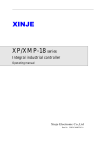
XP3-16 series integrated PLC&HMI User manual Xinje Electronic Co., Ltd No. PH C 04 20101217 3.3 This manual includes some basic precautions which you should follow to keep you safe and protect the products. These precautions are underlined with warning triangles in the manual. About other manuals that we do not mention please follow basic electric operating rules. Precautions Correct Application Please follow the precautions. If not, it may lead the control system incorrect or abnormal, even cause fortune lose. The models could only be used according to the manual, and an only be used along with the peripheral equipments recognized or recommended by Xinje Electronic. They could only work normally in the condition of be transported, kept and installed correctly, also please operate and maintain them according to the recommendation. Xinje Electronic Co., Ltd. Copyright reserved Without exact paper file allowance, copy, translate or using the manual is not allowed. Disobey this, people should take the responsibility of loss. We reserve all the right of expansions and their design patent. Duty Declare We have checked the manual, its content fits the hardware and software of the products. As mistakes are unavoidable, we couldn’t promise all correct. However, we would check the data in the manual frequently, and in the next edition, we will correct the necessary information. Your recommendation would be highly appreciated. Catalog 1 XP3-16 SERIES INTRODUCTION ......................................................................................... 1 1-1. INTRODUCTION ................................................................................................................... 1 1-1-1. Characteristics ........................................................................................................... 1 1-1-2. Name rule................................................................................................................... 1 1-2. GENERAL SPECIFICATION ..................................................................................................... 2 1-2-1. Product specification ........................................................................................................ 2 1-2-2. Special function ................................................................................................................ 4 1-3. PART INTRODUCTION ........................................................................................................... 5 1-3-1. Structure........................................................................................................................... 5 1-3-2. Function buttons............................................................................................................... 6 1-3-3. Terminals ......................................................................................................................... 6 1-3-4. Download and communication port .................................................................................. 7 1-4. DIMENSION ......................................................................................................................... 7 2 I/O AND WIRING ......................................................................................................................... 9 2-1. INPUT SPEC............................................................................................................................... 9 2-2. RELAY OUTPUT ....................................................................................................................... 11 2-3. TRANSISTOR OUTPUT .............................................................................................................. 13 3 PLC AND HMI PROGRAMMING.......................................................................................... 14 3-1. PLC PROGRAMMING ............................................................................................................... 14 3-2. INSTRUCTIONS........................................................................................................................ 15 3-2-1. basic instructions............................................................................................................ 15 3-2-2. Application instructions .................................................................................................. 17 3-2-3. Special instructions ........................................................................................................ 21 3-3. HMI PROGRAMMING............................................................................................................... 23 3-3-1. Make a project................................................................................................................ 23 3-3-2. Tools and parts ............................................................................................................... 25 APPENDIX 1 SPECIAL AUXILIARY REGISTER ..................................................................................... 27 APPENDIX 2 SPECIAL DATA REGISTER ............................................................................................. 35 APPENDIX 3 SPECIAL FLASH REGISTER ........................................................................................... 41 Preface Thank you for purchasing Xinje XP3-16 series integral industrial controller, please read the manual before operating. Manual purpose This manual provides user with the guide of using and operating our product, it includes the product characteristics, spec explanation, using method, etc. This manual contains product summarization, exterior layout, PLC program, and HMI editing. The details please refer to XC series PLC manual and TH series HMI manual. Summarization: introduce the product characteristics, specs, dimension, installation. Exterior layout: introduce the product power spec, in-out layout. PLC program: introduce how to program in PLC. HMI picture: introduce how to edit picture in TH. Exterior extension: introduce extension ability of the product. Suitable people This manual aims to below users: Terminal user Debugging person Technology support person Make sure you have read the safety notice before operating. Scope This manual applies to the XP3-16 series integral industrial controller. Tele-document Xinje provides user with press document and tele-document: User CD Contained software, manual and application examples Xinje website Welcome to www.xinje.com download center to find electronic document. Contact us If you have any questions, please contact us. Tel: 86-0510-85134136 Fax: 86-0510-85111290 Address: 4th Floor, Building 7, Originality Industrial Park, Liyuan Development Zone, Wuxi City, Jiangsu province, China Safety notes Read the manual carefully before operating. Be aware of the safety and correct operation. The content below is focus on XP3-16 series products only. Please safekeeping the manual, put in somewhere easy to get and read and give the manual to final user. ◎ Notice items ◎ ATTENTION ● Do not put the wire close to cable, keep 10cm distance at least. ● Do not change the inside module of product or it may cause fault, error action, loss, fire. ● When it smelly or noisy, cut the power immediately (short tweet after power on is normal). ● Do not press the screen with pen, screwdriver or other sharp tools, it may cause screen break or error. ● For installing the product, tighten the screws to avoid loose. ● Transport, install, store, assemble and maintain the product accurately to avoid breaking. DANGEROUSNESS ● Confirm the power voltage and wire connection before turn on the power in order to avoid breaking ● Do not touch the connection point to avoid getting an electric shock ● Do not open the back cover board ● Cut all the power before installation and take-down to avoid error and fault ● Please use in the surrounding the manual stated to avoid accident ● Do not use the product under the condition of high frequency radiation, strong magnetic field to avoid interference XP3-16 series manual 1 XP3-16 series introduction 1-1. Introduction 1-1-1. Characteristics Integrated logical control, analog I/O, HMI in one unit Digital input: 8 points, optical isolation, first 2 channels are high speed opto-isolator, others are general opto-isolator Digital output: 8 points, the first channel is transistor output (NPN open collector), others are relay output Analog extension: enable to expand 2 BD boards, the types includes XP3 -3AD2DA-BD2, XP3 -3AD3PT-BD2, XP3 -3PT-P-BD2, XP3-4AD2DA-BD2, XP3-3TC-P-BD2 LCD: 192*64 pixels, 3.7 inches, monochrome, use life up to 20000 hours Up to 26 function buttons, can be set freely, flexible and accurate Support high speed count, high speed pulse, external interruption Multi-functional download port: download PLC and HMI program with the same cable Compact design, save the space of control cabinet 1-1-2. Name rule 1: Series name XP3: monochrome LCD 2: PLC type 3: XC3 series 3: I/O points 16: 8 input, 8 output 4: Output type R: relay output T: transistor output RT: mixed transistor and relay output Extension BD 1 XP3-16 series manual Type Explanation XP3-3AD2DA-BD2 3 channels 0~10V analog input, 14-bit precision; 2 channels 0~20mA/0~10V analog output, 10-bit precision XP3-3AD3PT-BD2 3 channels 0~10V analog input, 14-bit precision; 3 channels PT100 thermal resistor input, resolution is 0.1℃, temperature range -100~350℃ XP3-3PT-P-BD2 3 channels PT100 input, PID inside, resolution is 0.1℃, temperature range -100~350℃ XP3-3TC-P-BD2 3 channels K-type thermocouple input, PID inside, resolution is 0.1℃, temperature range 0-970℃ XP-4AD2DA-BD2 4 channels 0~10V analog input, 2 channels 0~20mA/0~10V analog output 1-2. General specification 1-2-1. Product specification Electrical spec Item Electrical Environment Structure Interface HMI spec Spec Input voltage AC100V~240V Rated frequency 50/60Hz Allowable momentary power failure time Time ≤ 0.5 AC period, interval ≥1s Withstanding voltage AC1000V-10mA 1 minute (signal and ground) Insulation resistor About 10MΩ, DC500V (signal and ground) Operation temperature 0~50℃ Storage temperature –10~60℃ Ambient humidity 20~85% (no condensation) Vibration resistance 10~25Hz (X, Y, Z each direction is 30 minutes 2G) Interference immunity Voltage noise: 1000Vp-p Ambient air No corrosive gas Protection IP20 Cooling Natural air cooling Dimension 172.0*121.0*56.5 mm Installation dimension 164.0*113.0 mm Download port RS-232 Communication port RS-485 XP3-16 series manual Item Screen Memory Spec Type Yellow-green color LCD LCD size 3.7 inches Use life 20000 hours, 24 hours run under the ambient temperature 25℃ Display area 192*64 Contrast Adjust by potentiometer Language Chinese, English, Spanish, Korean and so on Font Lattice font, vector font Touch mode Untouchable Screen 64KB FlashROM Data 4KB SRAM PLC spec Item Program execution mode Cyclic scan Programming mode Instruction, ladder chart, visual C Operation speed 0.3µs Latched Spec FlashROM and Li-battery ※1 User program capacity 128K I/O points Input 8 points; output 8 points Internal coil (M) 8768 points Flow (S) 1024 Timer (T) Counter (C) Points 640 points Spec 100ms timer: 0.1~3276.7 s 10ms timer: 0.01~327.67 s 1ms timer: 0.001~32.767 s Points 640 points Spec 16-bit counter: 0~32767 32-bit counter: -2147483648~+2147483647 Data register (D) 9024 words FlashROM register (FD) 2048 words High speed functions High speed count, pulse output, external interruption Scheduled scan time 0~99ms Password protection 6-bit ASCII Self diagnosis Power-on self test, monitoring timer, grammar check ※1: the max capacity in encrypting download mode 3 XP3-16 series manual 1-2-2. Special function 1. High speed count XP3-16 series Incremental mode Pulse + direction mode AB phase mode C600C602 C604 C606 C608 C610 C612 C614 C616 C618 C620C622 C624 C626 C628 C630 C632 C634 Max frequency 10K 10K 10K 10K 10K 10K 5K 4-time frequency 5K √ Count interruption √ X000 U √ √ √ √ X001 X002 U A Dir B U X003 X004 √ U A Dir B U X005 U 2. High speed pulse XP3-16T: Y0, max speed is 200 kHz XP3-16RT: Y0, max speed is 200 kHz XP3-16R: not support 3. External interruption Input Pointer Suppress interruption Rising interruption Falling interruption X7 I0100 I0101 M8051 X6 I0200 I0201 M8052 4. Frequency measurement Type Input XP3-16 series X4、X5 Notes: the details please refer to XC series PLC manual. √ XP3-16 series manual 1-3. Part introduction 1-3-1. Structure Display area Numeric buttons Function buttons Download port Power supply Output RS485 port Input 5 XP3-16 series manual 1-3-2. Function buttons Button Function Return to initial screen whatever the screen state. Initial screen can be set by user, default is screen 1. Front page Next page Press it to change the register value. Press it again to cancel before pressing [ENT]. Write the changed data into the register, and continue to change next register. Alarm list button. Press it to see the alarm list. Clear the data when setting the register Set the positive /negative of data Numeric button (0~9) Function button (F1~F8) Notes: All the buttons in the above table can be set to other functions including set ON, set OFF, reverse, instant ON. 1-3-3. Terminals 1. Power supply terminals AC 220V L N FG 2. I/O terminals XP3-16 series manual 1-3-4. Download and communication port 1. Download port This port accords with RS232 standard and has double-download function. It can download both PLC and HMI program. The pin description: Pin Function Pin1 CTS Pin4 RXD Pin5 TXD Pin6 VCC Pin8 GND Mini Din 8 pins Notes: (1) Please use the cable supplied by XINJE company (2) Do not change the communication parameters (FD8210~8219) of download port, otherwise it cannot download program. 2. Communication port This port is the RS485 port (terminal A and B) of PLC. It supports Modbus-RTU protocol. 1-4. Dimension Product dimension (unit: mm) 56.5 1 2 3 4 5 6 7 8 6 7 8 9 2 3 4 5 1 0 121 172 111 162 7 XP3-16 series manual Open hole dimension (unit: mm) 164 113 XP3-16 series manual 2 I/O and wiring 2-1. Input spec Basic unit Input signal voltage DC24V±10% Input signal current 7mA/DC24V Input ON current Above 4.5mA Input OFF current Below 1.5mA Input response time About 10ms Input signal format Point input or NPN collector open transistor Circuit insulation Optical coupling insulation Input action display DC power supply COM R2 R1 X*0 R4 R3 X*7 LED is ON when input ON Input wiring The input current of XP3-16 series is supplied by internal 24V power supply. If using external power supply to drive the optical-electricity sensor, the supplier should be DC24V±4V. The output transistor of sensor should be NPN open collector. 9 XP3-16 series manual DC power supply +5V COM R2 R1 R6 R5 X*0 LED I=7mA R4 power supply DC24V R3 X*7 sensor Input points Connect input point and com point with non-voltage point or NPN open collector transistor to turn on the input. Input loop The first loop and the second loop are insulated by optical coupler, the second loop has C-R filter which can prevent wrong action caused by industry noise or input points oscillation. As the result, there will be a response delay for 10ms to the input points. There is digital filter in the input points. Input sensitivity Input current is DC 24V 7mA. To make the input reliable, the ON current should be above 3.5mA, the OFF current should be below 1.5mA. Typical wiring XP3-16 series manual 2-2. Relay output Relay output spec Power supply Below AC250V, DC30V Circuit insulation Machinery insulation Max loader Resistance load 3A Inductance load 80VA Lamp load 100W Min loader Response time DC5V 2mA OFF→ON 10ms ON→OFF 10ms Relay output circuit Output points Relay output has two common points. Different units can drive the loader of different power-voltage systems. Loop insulation It is electric insulated between relay output point and outside load circuit. Action indication Relay output coil produces close sound when it is on. Response time The response time is about 10ms transferring the ON or OFF signal from relay output coil to the output connection. Output current Output current is 3A per point to drive resistance load for voltage below AC250V. Inductance load is below 80VA (AC100V or AC200V) and lamp load is below 100W (AC100V or AC200V). Open leakage current There is no leakage current when output point is OFF, it can drive neon light. Use life of relay output point The standard life of inductance load such as contactor, solenoid valve: according to our experiment results, 20VA load is about 3 million times, 35VA load is about 1 million times, 80VA load is about 0.2 million times. However, the life will extend if parallel connect surge absorber with the load. 11 XP3-16 series manual Typical output wiring +24V relay drive circuit Y*0 To avoid burning PLC basic circuit set a fuse every 4 points 5A~10A AC power Load ~ supply <AC250V Y*1 Y*2 M Y*3 Relay output Note: T type has no relay output, do not connect AC220V, or the product will be broken. Output circuit construction ◆ ◆ For DC inductance load, please parallel connect with commutate diode. If not connect with the commutate diode, the point’s life will be decreased greatly. Please choose the commutate diode which allow inverse voltage endurance up to 5~10 times of the load’s voltage, ordinal current exceeds load current. Parallel connect AC inductance load with surge absorber can reduce noise and extend useful life of the points. DC load AC load XP3-16 series manual 2-3. Transistor output High speed pulse output Y*4 To avoid burning PLC basic circuit use suitable fuse for the load 1A DC power Load supply DC5~30V photo-electricity drive circuit Load Y*5 Load Y*6 Load Y*7 Wiring of pulse output and servo XP3-16 servo drive Make sure the current of servo drive optical coupling input is 8~15mA. 13 XP3-16 series manual 3 PLC and HMI programming 3-1. PLC programming 1. Please use XCPpro version 3.3 and above. 2. Please change the PLC type to XP3-16 when configure the BD board. If XP3-16 doesn’t not connect to BD board, it no need to change the PLC type, the system will indentify the type when downloading the program. After changing the PLC type, click PLC config/BD, it will show 2 BD boards configuration window: XP3-16 series manual 3. XP3-16 series use XP3-xxx-BD2 series BD board. Please distinguish it with other BD boards: (1) XC-xxx-BD: for XC series PLC (2) XP3-xxx-BD: for XP3-18 series integrated PLC&HMI (3) XP3-xxx-BD2: for XP3-16 series integrated PLC&HMI 4. XP3-4AD2DA-BD2 can only install on the left extension place of XP3-16. Others can install on both places. The details please refer to XP3 series extension BD2 board manual. Notes: for the detailed information of PLC, please refer to XC series PLC manual. 3-2. Instructions 3-2-1. basic instructions Instruction Function LD Initial logic normally open contactor LDI Initial logic normally close contactor AND Serial connection normally open contactor ANI Serial connection normally close contactor 15 XP3-16 series manual OR Parallel connection normally open contactor ORI Parallel connection normally close contactor LDP Initial logic rising-edge of pulse LDF Initial logic falling-edge of pulse ANDP Serial connection rising-edge of pulse ANDF Serial connection falling-edge of pulse ORP Parallel connection rising-edge of pulse ORF Parallel connection falling-edge of pulse LDD Read normally open contactor LDDI Read normally close contactor ANDD Read normally open contactor, serial connection ANDDI Read normally close contactor, serial connection ORD Read normally open contactor, parallel connection ORDI Read normally close contactor, parallel connection OUT Coil drive OUTD Output to the contactor ORB Parallel connection of serial circuit block ANB Serial connection of parallel circuit block MCS New generatrix start MCR Generatrix reset ALT Negate the coil PLS ON for one scanning period at rising-edge of pulse PLF ON for one scanning period at falling-edge of pulse SET Keep the coil ON XP3-16 series manual RST Clear the coil-ON state TMR Timer drive OUT Counter drive RST Reset the contactor, clear the current value END Operate output/input and return to step 0 GROUP Block folding start GROUPE Block folding end 3-2-2. Application instructions Type Instruction Process CJ Condition jump CALL Call the subprogram SRET Subprogram return STL Process start STLE Process end SET Open assigned process, close current process ST Data Function Open assigned process, not close current process FOR Cycle start NEXT Cycle end FEND Main program end LD= Initial logic ON when (S1)=(S2) LD> Initial logic ON when (S1)>(S2) LD< Initial logic ON when (S1)<(S2) LD<> Initial logic ON when (S1)≠(S2) comparison 17 XP3-16 series manual Data LD>= Initial logic ON when (S1)≥(S2) LD<= Initial logic ON when (S1)≤(S2) AND= Serial connection ON when (S1)=(S2) AND> Serial connection ON when (S1)>(S2) AND< Serial connection ON when (S1)<(S2) AND<> Serial connection ON when (S1)≠(S2) AND>= Serial connection ON when (S1)≥(S2) AND<= Serial connection ON when (S1)≤(S2) OR= Parallel connection ON when (S1)=(S2) OR> Parallel connection ON when (S1)>(S2) OR< Parallel connection ON when (S1)<(S2) OR<> Parallel connection ON when (S1)≠(S2) OR>= Parallel connection ON when (S1)≥(S2) OR<= Parallel connection ON when (S1)≤(S2) CMP Data comparison ZCP Data zone comparison MOV Data transmission transmission BMOV Data block transmission FMOV Multi-point repeat transmission EMOV Float transmission FWRT Write into FlashROM MSET Multi-set ZRST Multi-reset SWAP Exchange the high byte and low byte on XP3-16 series manual Data XCH Exchange two values ADD Addition SUB Subtraction MUL Multiplication DIV Division INC Plus one DEC Minus one calculation Type Instruction Function Data MEAN Get the mean value WAND Logic and calculation Data shift WOR Logic or WXOR Logic xor CML Negate NEG Negative SHL Arithmetic shift left SHR Arithmetic shift right LSL Logic shift left LSR Logic shift right ROL Rotate left ROR Rotate right SFTL Bit shift left SFTR Bit shift right WSFL Word shift left 19 XP3-16 series manual Data WSFR Word shift right WTD Word convert to double word FLT 16-bit integer convert to float FLTD 64-bit integer convert to float conversion Float INT Float convert to integer BIN BCD convert to binary BCD Binary convert to BCD ASCI Hex convert to ASCII HEX ASCII convert to hex DECO Decoding ENCO High-bit encoding ENCOL Low-bit encoding GRY Binary convert to gray code GBIN Gray code convert to binary ECMP Float comparison EZCP Float zone comparison EADD Float addition ESUB Float subtraction EMUL Float multiplication EDIV Float division ESQR Float square calculation SIN Float sine COS Float cosine TAN Float tangent XP3-16 series manual Clock ASIN Float arcsine ACOS Float arccosine ATAN Float arctangent TRD Read clock data TWR Write clock data 3-2-3. Special instructions Type Instruction Function High-speed HSCR Read 32-bit high-speed counter HSCW Write 32-bit high-speed counter count MODBUS OUT 24-segment high-speed count interruption RST High-speed count reset COLR MODBUS read coil INPR MODBUS read input coil communication Free format COLW MODBUS write single coil MCLW MODBUS write multi-coil REGR MODBUS read register INRR MODBUS read input register REGW MODBUS write single register MRGW MODBUS write multi-register SEND Free format send data RCV Free format receive data communication CANBUS CCOLR CANBUS read coil 21 XP3-16 series manual communication CCOLW CANBUS write coil CREGR CANBUS read register CREGW CANBUS write register CSEND CAN send CRECV CAN receive Type Instruction Precise timing STR Interruption Read &write Precise timing STRR Read precise timing register STRS Stop precise timing EI Enable the interruption DI Disable the interruption IRET Sequence block Function Interruption return SBLOCK Block start SBLOCKE Block end BSTOP Stop the block BGOON Continue running the stop block WAIT Wait FROM Read the module TO Write the module module Others FRQM Frequency measurement PWM Pulse width modulation PID NAME_C PID control C block The details please refer to XC series instruction manual. XP3-16 series manual 3-3. HMI programming The HMI program is edited in OP20 software. Please use the OP20 version 8.0 and above. OP20 is easy to learn and edit. The following we will introduce the programming method. 3-3-1. Make a project Build a new project 1. Build a project Open OP20 software, click file/new project or 2. Select the HMI type Select OP330 (XP) for XP3-16 series. . 3. Select the PLC type Select XINJE XC series PLC for XP3-16. 4. Edit the screen Below is the editing screen. The edit methods please refer to OP series manual. 23 XP3-16 series manual Screen download 1. Select the communication port Click file/select comm port to select the PC serial port. If select the wrong port, it will show below window: 2. Download Connect PC serial port to XP3-16 with downloading cable. Click to download. After finishing the download, it will show download successful window. Notes: (1) Do not cut the power when downloading, or you have to repower on and download again. (2) It is the same cable to download PLC and HMI program. XP3-16 series manual (3) Do not open XCPpro and OP20 software at the same time when downloading!! 3-3-2. Tools and parts Tools list Button Function Build a new project Open a project Save the project Make a new screen The property of the screen Copy screen Delete the screen Alarm list Set the initial screen, password and control properties Set the function button Download the program Part list Button Function Input text, support multi-language Dynamic text, show different text according to the machine state Vector text, enable to set the font and size Dynamic text, enable to set 254 kinds of states Lamp 25 XP3-16 series manual Data register input or monitor Set the function button Insert bmp picture Bar diagram, to show the analog quantity such as flow, pressure, liquid level Broken line diagram, fit for the data which change slowly Appendix 1 special auxiliary register PC status (M8000-M8003) ID Function Description M8000 Normally ON coil when running M8000 keeps being ON status when PLC is running M8001 Normally OFF coil when running M8001 keeps being OFF status when PLC is running M8002 Initial positive pulse coil M8002 be ON in first scan cycle M8003 Initial negative pulse coil M8003 be OFF in first scan cycle RTC (M8011-M8014) ID Function Description 5ms M8011 Shake with the cycle of 10ms 5ms 50ms M8012 Shake with the cycle of 100ms 50ms 0.5s M8013 Shake with the cycle of 10sec 0.5s 30s M8014 Shake with the cycle of 1min 30s 27 Flag (M8020-M8029) ID Function Description M8020 Zero The plus/minus operation result is 0 M8021 Borrow “borrow” occurs in minus operation M8022 Carry When carry occurs in plus operation or overflow occurs in bit shift operation M8023 M8026 RAMP Mode M8029 PC mode (M8030-M8038) ID Function Description M8030 PLC initializing M8031 Non-retentive register reset M8032 Retentive register reset M8033 Registers keep stopping When PLC changes from RUN to STOP, leave all content in mapping registers and data registers M8034 All output forbidden Set PC’s all external contacts to be OFF status M8038 Parameter setting Set communication parameters flag When driving this M, ON/OFF mapping memory of Y, M, S, TC and the current values of T, C, D are all reset to be 0 Stepper ladder (M8041-M8046) ID Function Description M8041 M8045 All output reset forbidden When shifting the mode, functions are forbidden all outputs reset M8046 STL status activate When M8047 activating, act when any device of S0~S999 turns to be ON Interruption (M8050-M8059) ID M8050 I000□ Function Description Forbid the input interruption 0 M8051 I010□ Forbid the input interruption 1 M8052 I020□ M8053 I030□ M8054 I040□ Forbid the input interruption 2 Forbid the input interruption 3 After executing EI instruction, even the interruption is allowed, but if M acts at this time, the correspond input interruption couldn’t act separately E.g.:when M8050 is ON, interrupt I000□ is forbidden Forbid the input interruption 4 M8055 I050□ M8056 I40□□ Forbid the input interruption 5 Forbid the time interruption 2 After executing EI instruction, even the interruption is allowed, but if M acts at this time, the correspond time interruption couldn’t act separately Forbid the interruption Forbid all interruption Forbid the time interruption 0 M8057 I41□□ M8058 I42□□ M8059 Forbid the time interruption 1 Error test (M8067-M8072) ID Function Description M8067 Operation error happen when calculating M8070 Scan time out M8071 No user program Internal codes parity error M8072 User program error execution codes or configure table parity error 29 Communication (M8120-M8148) ID Function Description M8120 M8121 Waiting to send via RS232 M8122 “sending by RS232” flag M8123 “RS232 receiving finish” flag M8124 RS232 receiving flag COM1 M8125 “Receive incomplete” flag M8126 Global signal M8127 “Accept error” flag M8128 “ Accept correct” flag acceptance ends normally, but the accepted data number is less than the required number M8129 M8130 COM2 M8131 Waiting to send via RS232 M8132 “sending by RS232” flag M8133 “RS232 receiving finish” flag M8134 RS232 receiving flag M8135 “Receive incomplete” flag M8136 Global signal M8137 “Accept error” flag M8138 “ Accept correct” flag acceptance ends normally, but the accepted data number is less than the required number M8139 M8140 COM3 M8141 Waiting to send via RS232 M8142 “sending by RS232” flag M8143 “RS232 receiving finish” flag M8144 RS232 receiving flag M8145 “Receive incomplete” flag M8146 Global signal M8147 “Accept error” flag M8148 “ Accept correct” flag M8149 acceptance ends normally, but the accepted data number is less than the required number High speed count interruption finished flag (M8150-M 8169) ID Counter ID Function Description M8150 C600 “Count Interruption Finished” Flag Set flag ON when count interruption finish M8151 C602 “Count Interruption Finished” Flag Set flag ON when count interruption finish M8152 C604 “Count Interruption Finished” Flag Set flag ON when count interruption finish M8153 C606 “Count Interruption Finished” Flag Set flag ON when count interruption finish M8154 C608 “Count Interruption Finished” Flag Set flag ON when count interruption finish M8155 C610 “Count Interruption Finished” Flag Set flag ON when count interruption finish M8156 C612 “Count Interruption Finished” Flag Set flag ON when count interruption finish M8157 C614 “Count Interruption Finished” Flag Set flag ON when count interruption finish M8158 C616 “Count Interruption Finished” Flag Set flag ON when count interruption finish M8159 C618 “Count Interruption Finished” Flag Set flag ON when count interruption finish M8160 C620 “Count Interruption Finished” Flag Set flag ON when count interruption finish M8161 C622 “Count Interruption Finished” Flag Set flag ON when count interruption finish M8162 C624 “Count Interruption Finished” Flag Set flag ON when count interruption finish M8163 C626 “Count Interruption Finished” Flag Set flag ON when count interruption finish M8164 C628 “Count Interruption Finished” Flag Set flag ON when count interruption finish M8165 C630 “Count Interruption Finished” Flag Set flag ON when count interruption finish M8166 C632 “Count Interruption Finished” Flag Set flag ON when count interruption finish M8167 C634 “Count Interruption Finished” Flag Set flag ON when count interruption finish M8168 C636 “Count Interruption Finished” Flag Set flag ON when count interruption finish M8169 C638 “Count Interruption Finished” Flag Set flag ON when count interruption finish Pulse output (M8170~M8238) ID Pulse ID M8170 PULSE_1 Function specification “sending pulse” flag Being ON when sending the pulse, M8171 overflow flag of “32 bits pulse sending” When overflow, Flag is on M8172 Direction flag 1 is positive direction, the correspond direction port is on “sending pulse” flag Being ON when sending the pulse, M8174 overflow flag of “32 bits pulse sending” When overflow, Flag is on M8175 Direction flag 1 is positive direction, the correspond direction port is on “sending pulse” flag Being ON when sending the pulse, overflow flag of “32 bits pulse sending” When overflow, Flag is on M8173 M8176 M8177 PULSE_2 PULSE_3 31 Direction flag 1 is positive direction, the correspond direction port is on “sending pulse” flag Being ON when sending the pulse, M8180 overflow flag of “32 bits pulse sending” When overflow, Flag is on M8181 Direction flag 1 is positive direction, the correspond direction port is on M8178 M8179 PULSE_4 Absolute, relative bit: ID function specification M8190 C600 (24 segments) 1 is absolute, 0 is relative M8191 C602 (24 segments) 1 is absolute, 0 is relative M8192 C604 (24 segments) 1 is absolute, 0 is relative M8193 C606 (24 segments) 1 is absolute, 0 is relative M8194 C608 (24 segments) 1 is absolute, 0 is relative M8195 C610 (24 segments) …… M8196 C612 (24 segments) M8197 C614 (24 segments) M8198 C616 (24 segments) M8199 C618 (24 segments) M8200 C620 (24 segments) M8201 C622 (24 segments) M8202 C624 (24 segments) M8203 C626 (24 segments) M8204 C628 (24 segments) M8205 C630 (24 segments) M8206 C632 (24 segments) M8207 C634 (24 segments) M8208 C636 (24 segments) M8209 C638 (24 segments) Pulse alarm flag (frequency change M8210 suddenly) 1 is alarm, 0 is correct PULSE_1 M8211 When flag is 1, stop sending alarm PULSE_1 Pulse alarm flag (frequency change M8212 suddenly) 1 is alarm, 0 is correct PULSE_2 M8213 Neglect the alarm or not When flag is 1, stop sending alarm PULSE_2 Pulse alarm flag (frequency change M8214 suddenly) 1 is alarm, 0 is correct PULSE_3 M8215 Neglect the alarm or not When flag is 1, stop sending alarm PULSE_3 Pulse alarm flag (frequency change M8216 suddenly) 1 is alarm, 0 is correct PULSE_4 M8217 Neglect the alarm or not When flag is 1, stop sending alarm PULSE_4 Neglect the alarm or not Pulse alarm flag (frequency change M8218 suddenly) 1 is alarm, 0 is correct PULSE_5 M8219 Neglect the alarm or not When flag is 1, stop sending alarm PULSE_5 Forward/reverse count ID M8238 Function Counter Nr. Positive/negative control C300~C498 Specification counter 0 is increment counter, 1 is decrement counter, default is 0 24 segments HSC interruption loop (M8270~M8289) ID Counter ID Specification M8270 24 segments HSC interruption loop (C600) if set it to be 1, then loop executing the interruption; or else execute only one time interruption; M8271 24 segments HSC interruption loop (C602) M8272 24 segments HSC interruption loop (C604) M8273 24 segments HSC interruption loop (C606) M8274 24 segments HSC interruption loop (C608) M8275 24 segments HSC interruption loop (C610) M8276 24 segments HSC interruption loop (C612) M8277 24 segments HSC interruption loop (C614) …… …… M8279 24 segments HSC interruption loop (C618) M8280 24 segments HSC interruption loop (C620) M8281 24 segments HSC interruption loop (C622) …… …… if set it to be 1, then loop executing the interruption; or else execute only one time interruption; 33 24 segments HSC interruption loop (C628) M8284 M8285 24 segments HSC interruption loop (C630) …… …… M8289 24 segments HSC interruption loop (C638) if set it to be 1, then loop executing the interruption; or else execute only one time interruption; Read & write the module (M8340~M8341) ID Function M8340 Read the expansion error flag (read instruction) M8341 Write the expansion error flag (write instruction) Specification BLOCK execution (M8630~M8730) ID Function Specification M8630 M8631 BLOCK1 is running flag M8632 BLOCK2 is running flag …… …… …… …… …… …… …… …… …… M8730 BLOCK100 is running flag Appendix 2 Special data register RTC (D8010-D8019) ID Function Specification D8010 The current scan cycle Unit:0.1ms D8011 The min. scan time Unit:0.1ms D8012 The max. scan time Unit:0.1ms D8013 Second (clock) 0~59 (BCD code) D8014 minute (clock) 0~59 (BCD code) D8015 hour (clock) 0~23 (BCD code) D8016 day (clock) 0~31 (BCD code) D8017 month (clock) 0~12 (BCD code) D8018 year (clock) 2000~2099 (BCD code) D8019 week (clock) 0 (Sunday)~6 (Saturday) (BCD code) Error check (D8067-D8098) ID Function Specification D8067 Operation error code’s Nr. The error of divide zero D8068 lock the Nr. of error code D8069 D8070 exceeded scan time D8074 Nr. of offset registers D Unit 1ms D8097 D8098 35 Communication (D8120-D8149) ID Function specification D8120 D8121 D8122 the left data RS232 should send D8123 Data number RS232 received D8126 Com 1 D8127 D8128 Communication error code 7: hardware error 8: CRC Parity error 9: station number error 10: no start code 11: no end code 12: communication time out Modbus communication error (the replied message from slaves when the master send errors) 0: correct 1: don’t support function ID 2: address error (overrun address) 3: Data error (the number of data) 8: saving data error (rewrite Flash) D8129 D8130 D8131 D8132 the left data RS232 should send D8133 Data number RS232 received D8136 Com2 D8137 D8138 Communication error code 7: hardware error 8: CRC check error 9: station number error 10: no start sign 11: no end sign 12: communication time out Modbus communication error (the replied message from slaves when the master send errors) 0:correct 1: don’t support function ID 2: address error(overrun address) 3: Data error ( the number of data) 8:saving data error ( rewrite Flash) D8139 D8140 D8141 Com 3 D8142 the left data RS232 should send D8143 Data number RS232 received D8146 D8147 D8148 Communication error code 7: hardware error 8: CRC check error 9: station number error 10: no start sign 11: no end sign 12: communication time out Modbus communication error (the replied message from slaves when the master send errors) 0:correct 1: don’t support function ID 2: address error(overrun address) 3: Data error ( the number of data) 8:saving data error ( rewrite Flash) D8149 HSC interruption state (D8150-D8169) ID Counter ID function D8150 C600 The current segment (No.n segment) D8151 C602 The current segment D8152 C604 The current segment D8153 C606 The current segment D8154 C608 The current segment D8155 C610 The current segment D8156 C612 The current segment D8157 C614 The current segment D8158 C616 The current segment D8159 C618 The current segment D8160 C620 The current segment D8161 C622 The current segment D8162 C624 The current segment D8163 C626 The current segment D8164 C628 The current segment D8165 C630 The current segment D8166 C632 The current segment D8167 C634 The current segment D8168 C636 The current segment D8169 C638 The current segment specification 37 Pulse output (D8170-D8220) ID Pulse ID D8170 PULSE_1 function specification The low 16 bits of accumulated pulse number D8171 The high 16 bits of accumulated pulse number D8172 The current segment (means Nr.n segment) D8173 PULSE_2 The low 16 bits of accumulated pulse number D8174 The high 16 bits of accumulated pulse number D8175 The current segment (means Nr.n segment) D8176 PULSE_3 The low 16 bits of accumulated pulse number D8177 The high 16 bits of accumulated pulse number D8178 The current segment (means Nr.n segment) D8179 PULSE_4 The low 16 bits of accumulated pulse number D8180 The high 16 bits of accumulated pulse number D8181 The current segment (means Nr.n segment) D8190 PULSE_1 PULSE_2 PULSE_3 PULSE_4 The low 16 bits of the current accumulated current pulse number Only XC5-32RT-E (4PLS) model has The high 16 bits of the current accumulated current pulse number D8197 ID The low 16 bits of the current accumulated current pulse number The high 16 bits of the current accumulated current pulse number D8195 D8196 The low 16 bits of the current accumulated current pulse number The high 16 bits of the current accumulated current pulse number D8193 D8194 The low 16 bits of the current accumulated current pulse number The high 16 bits of the current accumulated current pulse number D8191 D8192 Only XC5-32RT-E (4PLS) model has Pulse ID Function Description D8210 PULSE_1 Error segment number PULSE_1 D8212 PULSE_2 Error segment number PULSE_2 D8214 PULSE_3 Error segment number PULSE_3 D8216 PULSE_4 Error segment number PULSE_4 D8218 PULSE_5 Error segment number PULSE_5 D8220 Frequency Testing Precision indicate the bit Nr. Behind the decimal dot, 1 means *10, 2 means *100 Absolute positioning/relative positioning/origin returning (D8230-D8239) ID D8230 D8231 D8232 D8233 D8234 D8235 D8236 D8237 D8238 D8239 Pulse PULSE_1 PULSE_2 PULSE_3 PULSE_4 PULSE_5 Function Description Rising time of the absolute/relation position instruction (Y0) Falling time of the origin return instruction (Y0) Rising time of the absolute/relation position instruction (Y1) Falling time of the origin return instruction (Y1) Rising time of the absolute/relation position instruction (Y2) Falling time of the origin return instruction (Y2) Rising time of the absolute/relation position instruction (Y3) Falling time of the origin return instruction (Y3) Rising time of the absolute/relation position instruction Falling time of the origin return instruction Read & write the module (D8315-D8316) ID Function D8315 Read the expansion’s error type D8316 Write the expansion’s error type Description Sequential function BLOCK (D8630-D8730) ID Function Description D8630 D8631 The current executing instruction of BLOCK1 The value is used when BLOCK is monitoring D8632 The current executing instruction of BLOCK2 The value is used when BLOCK is monitoring …… …… …… 39 …… …… …… …… …… …… D8730 The current executing instruction of BLOCK100 The value is used when BLOCK is monitoring Error message of module (D8600-D8627) ID Function D8600 Read the expansion’s error times D8601 Read the expansion’s error specification expansion’s CRC parity error expansion’s address error expansion’s accepted data length error expansion’s accept buffer zone overflow 5. expansion’s timeout error 6. CRC parity error when PLC is accepting data 7. unknown error Expansion ID 1. 2. 3. 4. Expansion 1 D8602 write the expansion’s error times D8603 write the expansion’s error D8604 Read the expansion’s times D8605 Read the expansion’s error D8606 write the expansion’s error times D8607 write the expansion’s error D8608 Read the expansion’s times D8609 Read the expansion’s error D8610 write the expansion’s error times D8611 write the expansion’s error D8612 Read the expansion’s times D8613 Read the expansion’s error D8614 write the expansion’s error times D8615 write the expansion’s error …… …… …… …… …… …… …… …… …… D8624 Read the expansion’s times D8625 Read the expansion’s error D8626 write the expansion’s error times …… …… Expansion 2 …… …… Expansion 3 …… …… Expansion 4 …… Expansion 7 D8627 write the expansion’s error …… Appendix 3 Special Flash register 1. I filter ID Function FD8000 input filter time of X port Initial Value Description 10 Unit: ms FD8002 0 FD8003 0 …… 0 FD8009 0 2. I mapping ID Function Initial value Description FD8010 X00 corresponds with I** 0 X0 corresponds with number of input image I** FD8011 X01 corresponds with I** 1 Initial values are all decimal FD8012 X02 corresponds with I** 2 …… …… FD8073 X77 corresponds with I** 63 3. O mapping ID Function Initial value Description FD8074 Y00 corresponds with I** 0 Y0 corresponds with the number of output image O** FD8075 Y01 corresponds with I** 1 Initial value are all decimal FD8076 Y02 corresponds with I** 2 …… …… FD8137 Y77 corresponds with I** 63 4. I property ID function Initial value Description FD8138 X00 property all be 0 0: positive logic; others: negative logic FD8139 X01 property FD8140 X02 property …… …… FD8201 X77 property 41 5. power-off retentive area of soft components ID Function Initial Value FD8202 Start tag of D power off retentive area 4000 FD8203 Start tag of M power off retentive area 3000 FD8204 Start tag of T power off retentive area 640 FD8205 Start tag of C power off retentive area 320 FD8206 Start tag of S power off retentive area 512 FD8207 Start tag of ED power off retentive area 0 FD8209 Pulse director and pulse delay time setting 50ms 6. Communication ID Function Initial Description FD8210 Communicate Mode (station number) 1 255 (FF) is free mode, 1~254 is modbus station number FD8211 Communicate format 8710 Baud rate, Data bit, stop bit, parity FD8212 Judgment timeout time of ASC 3 Unit ms, if set to be 0, it means no timeout waiting FD8213 Judgment timeout time of reply 300 Unit ms, if set to be 0, it means no timeout waiting FD8214 Start ASC 0 High 8 bits invalid FD8215 End ASC 0 High 8 bits invalid FD8216 Free format setting 0 8/16 bits buffer; With/without start bit, With/without stop bit FD8220 Communicate Mode (station number) 8710 255 (FF) is free mode, 1~254 is modbus station number FD8221 Communicate format 3 Baud rate, Data bit, stop bit, parity FD8222 Judgment timeout time of ASC 300 Unit ms, if set to be 0, it means no timeout waiting FD8223 Judgment timeout time of reply 0 Unit ms, if set to be 0, it means no timeout waiting FD8224 Start ASC 0 High 8 bits invalid FD8225 End ASC 0 High 8 bits invalid FD8226 Free format setting 8710 8/16 bits buffer; With/without start bit, With/without stop bit FD8230 Communicate Mode (station number) 8710 255 (FF) is free mode, 1~254 is modbus station number FD8231 Communicate format 3 Baud rate, Data bit, stop bit, parity COM1 COM2 COM3 FD8232 Judgment timeout time of ASC FD8233 Judgment timeout time of reply FD8234 FD8235 FD8236 300 Unit ms, if set to be 0, it means no timeout waiting 0 Unit ms, if set to be 0, it means no timeout waiting Start ASC 0 High 8 bits invalid End ASC 0 High 8 bits invalid 8710 8/16 bits buffer; With/without start bit, With/without stop bit Free format setting 7. Subsection Power-off Retentive Zone of Timer T Nr. Function FD8323 Set the retentive zone’s start tag of 100ms non-accumulation timer FD8324 Set the retentive zone’s start tag of 100ms accumulation timer FD8325 Set the retentive zone’s start tag of 10ms non-accumulation timer FD8326 Set the retentive zone’s start tag of 10ms accumulation timer FD8327 Set the retentive zone’s start tag of 1ms non-accumulation timer FD8328 Set the retentive zone’s start tag of 1ms accumulation timer FD8329 Set the retentive zone’s start tag of 1ms precise timer Initial Value 8. Subsection power-off retentive zone of counter C Nr. Function FD8330 Set the retentive zone’s start tag of 16 bits positive counter FD8331 Set the retentive zone’s start tag of 32 bits positive/negative counter FD8332 Set the retentive zone’s start tag of single-phase HSC FD8333 Set the retentive zone’s start tag of dual-phase HSC FD8334 Set the retentive zone’s start tag of AB-phase HSC Initial Value ※1:If you change special FLASH memory, it will take into effect after restart the PLC 43 Xinje Electronic Co., Ltd. 4th Floor Building 7,Orignality Industry park, Liyuan Development Zone, Wuxi City, Jiangsu Province 214072 Tel: (510) 85134136 Fax: (510) 85111290 www.xinje.com