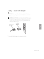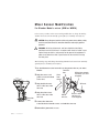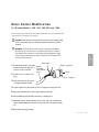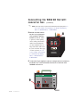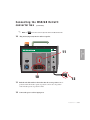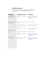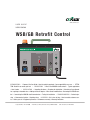
1
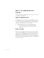
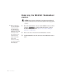
www.conairnet.com
USER GUIDE
UGB013/0506
WSB/GB Retrofit Control
Feeder Selection
Power
Feeder
Fuse
Feeders
3&4
Ethernet
Solenoid Valves
Main
Fuse
230V
Feeders
5&6
On
Off
Feeder Power
INTRODUCTION • Purpose of the User Guide • How the guide is organized • Your responsibilities as a user • ATTENTION: Read this so no one gets hurt
• How it works
•
• DESCRIPTION • What is the WSB/GB retrofit control? • Typical applications
INSTALLATION • Unpacking the boxes • Preparing for installation • Determining if your blender
has a pulsing or standard valve • Adding a load cell adapter • Mixer sensor modifications • Removing the WSB/GB control • Connecting the WSB/GB retrofit convertor box • Testing the installation • TROUBLESHOOTING • Before beginning • A few words of caution • Replacing fuses • APPENDIX • We’re here to help • How to contact customer service • Before you call • Equipment guarantee • Performance warranty • Warranty limitations
Corporate Office: 412.312.6000 l Instant Access 24/7 (Parts and Service): 800.458.1960 l Parts and Service: 814.437.6861
Please record your equipment’s
model and serial number(s) and
the date you received it in the
spaces provided.
It’s a good idea to record the model and serial number(s) of your equipment and
the date you received it in the User Guide. Our service department uses this information, along with the manual number, to provide help for the specific equipment
you installed.
Please keep this User Guide and all manuals, engineering prints and parts lists
together for documentation of your equipment.
Date:
Manual Number: UGB013/0506
Serial Number(s):
Model Number(s):
DISCLAIMER: The Conair Group, Inc., shall not be liable for errors contained in this User Guide or
for incidental, consequential damages in connection with the furnishing, performance or use of
this information. Conair makes no warranty of any kind with regard to this information, including,
but not limited to the implied warranties of merchantability and fitness for a particular purpose.
Copyright 2006 l The Conair Group l All rights reserved
Ta b l e o f C o n t e n t s
1-1 I n t r o d u c t i o n
Purpose of the user guide . . . . . . . . . . . . . . . . . . . . . . . . . . . . . . . . 1-2
How the guide is organized . . . . . . . . . . . . . . . . . . . . . . . . . . . . . . 1-2
Your responsibilities as a user . . . . . . . . . . . . . . . . . . . . . . . . . . . . . 1-3
ATTENTION: Read this so no one gets hurt . . . . . . . . . . . . . . . . . . . 1-4
2-1 D e s c r i p t i o n
What is the WSB/GB retrofit control? . . . . . . . . . . . . . . . . . . . . . . . .2-2
Typical applications . . . . . . . . . . . . . . . . . . . . . . . . . . . . . . . . . . . . .2-2
How it works . . . . . . . . . . . . . . . . . . . . . . . . . . . . . . . . . . . . . . . . . .2-2
3-1 I n s t a l l a t i o n
Unpacking the boxes . . . . . . . . . . . . . . . . . . . . . . . . . . . . . . . . . . . 3-2
Preparing for installation . . . . . . . . . . . . . . . . . . . . . . . . . . . . . . . . . 3-3
Determining if your Blender has pulsing or standard valves . . . . . . 3-4
Adding a load cell adapter (GBM and WSBM) . . . . . . . . . . . . . . . . . 3-5
Mixer sensor modifications (GBM and WSBM) . . . . . . . . . . . . . . . . . 3-6
Mixer sensor modifications (100-1800). . . . . . . . . . . . . . . . . . . . . . 3-7
Removing the WSB/GB control . . . . . . . . . . . . . . . . . . . . . . . . . . . . 3-8
Connecting the WSB/GB retrofit converter box. . . . . . . . . . . . . . . . . 3-9
Testing the installation . . . . . . . . . . . . . . . . . . . . . . . . . . . . . . . . . 3-14
4-1 Tr o u b l e s h o o t i n g
Troubleshooting. . . . . . . . . . . . . . . . . . . . . . . . . . . . . . . . . . . . . . . . 4-2
Replacing fuses . . . . . . . . . . . . . . . . . . . . . . . . . . . . . . . . . . . . . . 4-3
Ta b l e o f C o n t e n t s l i
A Appendix
We’re here to help . . . . . . . . . . . . . . . . . . . . . . . . . . . . . . . . . . . . . A-1
How to contact customer service . . . . . . . . . . . . . . . . . . . . . . . . . . A-1
Before you call... . . . . . . . . . . . . . . . . . . . . . . . . . . . . . . . . . . . . . . A-1
Equipment guarantee . . . . . . . . . . . . . . . . . . . . . . . . . . . . . . . . . . A-2
Performance warranty . . . . . . . . . . . . . . . . . . . . . . . . . . . . . . . . . . A-2
Warranty limitations . . . . . . . . . . . . . . . . . . . . . . . . . . . . . . . . . . . . A-2
i i l Ta b l e o f C o n t e n t s
SECTION
1
Purpose of the user guide . . . . . . . . . . . . . . 1-2
How the guide is organized . . . . . . . . . . . . . 1-2
Yo u r r e s p o n s i b i l i t i e s a s a u s e r . . . . . . . . . . . 1 - 3
AT T E N T I O N :
Read this so no one gets hurt . . . . . . . . 1-4
Introduction l 1-1
1
Introduction
Introduction
Purpose of the User Guide
This User Guide describes the Conair WSB/GB Retrofit Control and
explains step-by-step how to install the control.
Before installing this product, please take a few moments to read the User
Guide and review the diagrams and safety information in the instruction
packet. You also should review manuals covering associated equipment in
your system. This review won’t take long, and it could save you valuable
installation and operating time later.
How the Guide is Organized
Symbols have been used to help organize the User Guide and call your
attention to important information regarding safe installation and operation.
Symbols within triangles warn of conditions that could be hazardous to users or
could damage equipment. Read and take precautions before proceeding.
1
Numbers indicate tasks or steps to be performed by the user.
◆
A diamond indicates the equipment’s response to an action performed by the user.
❒
An open box marks items in a checklist.
•
A circle marks items in a list.
✒
✐
1-2 l Introduction
Indicates a tip. A tip is used to provide you with a suggestion that will help you with
the maintenance and the operation of this equipment.
Indicates a note. A note is used to provide additional information about the steps
you are following throughout the manual.
Yo u r R e s p o n s i b i l i t y a s a U s e r
• Thorough review of this User Guide, paying particular attention
to hazard warnings, appendices and related diagrams.
• Thorough review of the equipment itself, with careful attention
to voltage sources, intended use and warning labels.
• Thorough review of instruction manuals for associated equipment.
• Step-by-step adherence to instructions outlined in this User Guide.
Introduction l 1-3
1
Introduction
You must be familiar with all safety procedures concerning installation, operation and maintenance of this equipment. Responsible safety procedures include:
AT T E N T I O N :
Read this so no one gets hurt
We design equipment with the user’s safety in mind. You can avoid the potential
hazards identified on this machine by following the procedures outlined below and
elsewhere in the User Guide.
WA R N I N G : I m p r o p e r i n s t a l l a t i o n , o p e r a t i o n , o r
servicing may result in equipment damage or
p e r s o n a l i n j u r y.
This equipment should be installed, adjusted, and serviced by qualified
technical personnel who are familiar with the construction, operation,
and potential hazards of this type of machine.
All wiring, disconnects, and fuses should be installed by qualified electrical technicians in accordance with electrical codes in your region.
Always maintain a safe ground. Do not operate the equipment at power
levels other than what is specified on the machine serial tag and data
plate.
WA R N I N G : Vo l t a g e h a z a r d
This equipment is powered by single-phase alternating current,
as specified on the machine serial tag and data plate.
Always disconnect and lock out the incoming main power source before
opening the electrical enclosure or performing non-standard operating
procedures, such as routine maintenance. Only qualified personnel
should perform troubleshooting procedures that require access to the
electrical enclosure while power is on.
1-4 l Introduction
SECTION
2
What is the WSB/GB retrofit control? . . . . . . 2-2
Ty p i c a l a p p l i c a t i o n s . . . . . . . . . . . . . . . . . . 2 - 2
How it works . . . . . . . . . . . . . . . . . . . . . . 2-2
Description
l 2-1
2
Description
Description
What is the WSB/GB Retrofit
Control?
The retrofit control converts the WSB/GB thumbwheel controller to the new touch
screen TrueBlend control technology.
Ty p i c a l A p p l i c a t i o n s
The WSB/GB Retrofit Control is used with existing WSB/GB blenders of all sizes
to convert the blender’s existing thumbwheel controller to the TrueBlend touch
screen control technology. Both four component and twelve component blender
configurations are supported with a six component limitation.
✐
NOTE: The WSB/GB retrofit can only be used on existing WSB/GB controllers
with 17-pin amphenol connectors and 24 volt DC solenoids. The WSB/GB
retrofit control is not available with older 8-pin or 14-pin models with 120
volt AC solenoids.
How it works
This will convert your thumbwheel blender control used to operate your blender
to the new touch screen TrueBlend control. You will follow the steps later in this
manual to remove your WSB/GB thumbwheel controller and replace it with the
WSB/GB retrofit control and a TrueBlend touch screen operator panel. Once you
have installed the touch screen control it will operate exactly as the TrueBlend control operates. You will use the TrueBlend manual as a guide to navigate through the
screens on your new control.
2-2 l Description
SECTION
3
Installation
Unpacking the boxes . . . . . . . . . . . . . . . . . 3-2
Preparing for installation . . . . . . . . . . . . . . 3-3
or standard valves . . . . . . . . . . . . . . . . 3-4
Adding a load cell adapter . . . . . . . . . . . . . 3-5
Mixer sensor modification (GBM and WSBM). . 3-6
Mixer sensor modification (100 -1800) . . . . . 3-7
Removing the WSB/GB thumbwheel control . . 3-8
Connecting the WSB/GB convertor box . . . . . 3-9
Te s t i n g t h e i n s t a l l a t i o n . . . . . . . . . . . . . . . 3 - 1 4
Installation l 3-1
3
Installation
Determining if your blender has pulsing
Unpacking the Boxes
The WSB/GB retrofit control comes in two boxes. The boxes should include:
1
WSB/GB converter box
2
6 M cable for TB operator interface
3
TrueBlend touch screen operator panel
4
Load cell adapter (if the retrofit control is to be
placed on the WSBM/GBM or WSB/GB100 model.)
4 Load cell
adapter
2 6 M cable for TB
operator interface
1
WSB/GB Retrofit Control
3 TrueBlend touch
screen operator
panel
1 Carefully remove the control and components from their shipping containers,
and set upright.
2 Remove all packing material, protective paper, tape, and plastic.
3 Carefully inspect all components to make sure no damage occurred during
shipping, and that you have all the necessary hardware.
4 Take a moment to record serial numbers and electrical power specifications
in the blanks provided on the back of the the User Guide’s title page. The information will be helpful if you ever need service or parts.
3-2 l Installation
5 You are now ready to begin installation.
Preparing for Installation
The WSB/GB retrofit control is easy to install if you plan the location and prepare
the unit properly.
1 Before you plug in the WSB/GB converter box:
WARNING: The load cell adapter must be placed between the existing
load cell cable and the load cell connection on the retrofit kit before the
control is powered up. If the adapter is not in place and the unit is
powered up the WSB/GB retrofit box will be damaged.
❒ On all models it will be necessary to make a mixer sensor wiring modification to change the mixing chamber level sensor from normally
opened (N.O.) to normally closed (N. C.) . See the section entitled “Mixing
Chamber Level Sensor Modification,” later in this section for instructions on
modifying the wiring on the level sensor. You will need to complete this
before you plug in your WSB/GB retrofit control.
Installation l 3-3
3
Installation
❒ IMPORTANT: GBM and WSBM micro and 100 model blenders require
a load cell adapter to be placed between the existing load cell cable and
the load cell connection on the retrofit control. If you ordered the
WSB/GB retrofit kit to be placed on a model GBM/WSBM micro blender or
WSB/GB 100 model you should have received the load cell adapter with
your blender and it should be installed on the appropriate connection. If you
move the retrofit control kit from another larger blender at your facility to a
smaller micro or 100 model blender See the section entitled, “Adding a Load
Cell Adapter,” later in this section for instructions on adding a load cell
adapter. Contact Conair Parts 1 800-458-1960 if you need to purchase the
adapter.
Determining if your blender has
p u l s i n g va l v e s o r s t a n d a r d va l v e s
1. Listen as the blender with your original control connected operates. If you
hear a rapid pulsing sound you have pulsing valves. If you still are not sure
proceed to step 2.
CAUTION: Always disconnect and lock out the main power sources before accessing any
part of the blender. Moving parts and electrical power can cause severe personal injury.
2. Visually inspect the valves.
Standard Vertical
Valve
Vertical Pulse
Valve - shorter
and has a visible
cutaway in the
cylinder
Standard
Horizontal Valve
Horizontal Pulse
Valve - has a
white nylon piece
in the center of
the valve
3. Push the red slide switches into the correct position for Valve position 3
and Valve Position 4. Slide the switch to pulse if you have pulsing valves on
bin positions three and/or four and standard if you have standard valves on bin
position three and/or four.
3-4 l Installation
Adding a Load Cell Adapter
IMPORTANT!
WSB/GB micro blenders and 100 model blenders require a load cell adapter to be
placed between the existing load cell cable and the load cell connections on the
retrofit convertor box.
WARNING: Models GBM/WSBM micro blenders and 100 model blenders require a
load cell adapter to be placed between the existing load cell cable and the load cell
connections on the retrofit control before the control is powered up. If the
adapter is not in place and the unit is powered up the WSB/GB retrofit
convertor box will be damaged.
1 Connect the load cell adapter to the existing load cell cable.
Installation l 3-5
3
Installation
Existing Load
Cell Cable
Load Cell
Adapter
Mixer Sensor Modification
For Blender Models: micro (GBM or WSBM)
It is necessary to make a mixer sensor wiring modification to change the mixing
chamber level sensor from normally opened (N.O.) to normally closed (N. C.).
CAUTION: Always disconnect and lock out the main power sources before making
electrical connections. Electrical connections should be made only by qualified
personnel.
WARNING: All wiring, disconnects, and fuses should be installed by
qualified electrical technicians in accordance with electrical codes in your
region. Always maintain a safe ground. Do not operate the equipment at
power levels other than what is specified on the the machine serial tag
and data plate.
The following steps will change the mixing chamber level sensor from normally
opened (N.O.) to normally closed (N.C.).
1 See the illustration to the left and locate the junction box on your micro
blender.
2 Strip the sensor cord
jacket to locate the black
sensor wire.
Junction
box
Cord
from
sensor
White from remote
connector (cut and
stripped)
3 Strip the black sensor
Wire nut
wire to allow use of the
wire nut.
4 Strip the white sensor
wire to allow use of the
wire nut.
Junction
box
White
wire cut
Black in from
sensor (cut
and stripped)
5 Connect the white wire
to the black wire from the sensor cord with the wire nut.
6 Reinstall the junction box cover.
3-6 l Installation
Mixer Sensor Modification
For Blender Models: 100, 200, 400, 900 and 1800
The following steps will change the mixing chamber level sensor from normally
opened (N.O.) to normally closed (N.C.).
CAUTION: Always disconnect and lock out the main power sources before making
electrical connections. Electrical connections should be made only by qualified
personnel.
White wire
1 See the illustration to the right Mixing
and locate the male plug that
connects to the controller.
Brown- small pin
Chamber
Level Sensor
Cord
Black
2 Cut the sensor cord near the
plug.
Blue - large pin
3 Strip the jacket on the sensor
cord approximately 1 inch.
4 Cut the white wire off near the sensor cord jacket and tape the end.
5 Strip the remaining three wires approximately 1/2 inch.
6 Disassemble the plug housing and remove existing wires.
7 Install the brown, black and blue wires on the respective terminals as
shown. Terminating the wires incorrectly will cause circuit board damage.
8 Reassemble the plug housing.
Installation l 3-7
3
Installation
WARNING: All wiring, disconnects, and fuses should be installed by
qualified electrical technicians in accordance with electrical codes in
your region. Always maintain a safe ground. Do not operate the equip
ment at power levels other than what is specified on the the machine
serial tag and data plate.
Removing the WSB/GB Thumbwheel
control
CAUTION: Always disconnect and lock out the main power sources before making electrical connections. Electrical connections should be made only by qualified
personnel.
✒
TIP: It may help you to
know that, the WSB/GB
1
Record the model number and series of the WSB/GB control you will be
removing. IMPORTANT you will need this information to set up the
TrueBlend touch screen control. See the section entitled, “Testing the
Installation,” in this section.
2
Remove all of the connections from the thumbwheel controller.
3
Lift the thumbwheel controller and remove it from the blender control
shelf.
retrofit control has the
same input/output connections as the WSB/GB
thumbwheel control. It will
be necessary to make
these connections to the
retrofit control box to
operate the new touch
screen control.
Instructions for making
the connections appear on
the following pages.
3-8 l Installation
Connecting the WSB/GB Retrofit
converter box
CAUTION: Always disconnect and lock out the main power sources before making
electrical connections. Electrical connections should be made only by qualified
personnel.
The retrofit converter box has the same input/output connections as the WSB/GB
thumbwheel control. It will be necessary to make these connections to the retrofit
converter box to operate the new touch screen control.
1 Lift the WSB/GB converter box and position it onto the blender control
shelf. Your new box is the same size as the thumbwheel control.
230V
230V
Pulse
Valve
Standard
Valve
Mixer Fuse
Feeder Selection
Power
Feeder
Fuse
Standard
Valve
Feeders
3&4
Load Cells
Ethernet
Main
Fuse
230V
Mixer Level Sensor
Touch Screen
Solenoid Valves
Feeders
5&6
On
Off
Feeder Power
3
2 Visually inspect the front, left side and right side of the converter box to
familiarize yourself with the connections.
3 Make sure that the toggle switch is in the “off” position.
Installation l 3-9
3
Valve
Position
4
Installation
Valve
Position
3
Pulse
Valve
Connecting the WSB/GB Retrofit
c o n v e r t e r b o x (continued)
CAUTION: Always disconnect and lock out the main power sources before making
electrical connections. Electrical connections should be made only by qualified
personnel.
4 Connect the level sensor cable from the mix chamber to the receptacle
labeled “Mixer Level Sensor” on the control box. The cable is a threeprong, twist lock connector. Before you make this connection make sure
that you have followed the instructions for making the level sensor modifications, See the sections entitled “Preparing for Installation” and “Mixer
Sensor Modifications,” in this manual.
Mixer Fuse
Mixer Level Sensor
Alarm Horn
4
5 Plug the output power into the WSB/GB mix motor.
3-10 l Installation
5
Connecting the WSB/GB Retrofit
c o n v e r t e r b o x (continued)
Valve
Position
3
Valve
Position
4
Pulse
Valve
Pulse
Valve
230V
230V
Standard
Valve
✐
NOTE: This area of the control will only
be seen on WSB/GB retrofit converter boxes that have been
ordered to be placed on a blender
that has pulsed valves.
Touch Screen
6
7
WARNING: Models GBM and WSBM micro blenders require a load
cell adapter to be placed between the existing load cell cable and
the load cell connection on the retrofit control before the control is
powered up. If the adapter is not in place and the unit is powered
up the WSB/GB retrofit box will be damaged. See the section entitled,
“Adding a Load Cell Adapter,” in this section.
6 Connect the load cell cable, a DB25 connector. This will supply the voltage for the load cell and collect the weight signal.
7 Choose a location for the TrueBlend touch screen operator panel to
be remote mounted. Mount the TrueBlend touch screen panel. (See the
TrueBlend user guide for mounting instructions for the touch screen control.) Connect the touch screen to the DB25 connector on the
WSB/GB retrofit converter box.
Installation l 3-11
3
Load Cells
Installation
Standard
Valve
Connecting the WSB/GB Retrofit
c o n v e r t e r b o x (continued)
✐
NOTE: Step 8 only needs to be performed on blenders that have pulsing valves. See
the section entitled, “Determining if your Blender has Pulsing
Valves or Standard Valves,” in this manual.
8 Push the red slide switches
into the correct position for
Valve position 3 and Valve
Position 4. Slide the switch
to pulse if you have pulsing
valves on bin positions three
and/or four and standard if
you have standard valves on
bin position three and/or four.
If you do not know what types
of valves you have, See, the
section entitled, “Determining
if your Blender has Pulsing
Valves or Standard Valves”
in this manual.
8
Valve
Position
3
Valve
Position
4
230V
230V
Pulse
Valve
Pulse
Valve
Standard
Valve
Standard
Valve
Load Cells
Touch Screen
9 Connect the 17-pin amphenol connector coming from the air solenoid on
the blender tray to the item labeled solenoid valve on the front of the
WSB/GB converter box.
Feeder Selection
Power
Feeder
Fuse
9
Feeders
3&4
Ethernet
Solenoid Valves
Main
Fuse
230V
Feeders
5&6
On
Off
Feeder Power
3-12 l Installation
Connecting the WSB/GB Retrofit
c o n v e r t e r b o x (continued)
✐
10
NOTE: You cannot control more than six components with the TrueBlend Retrofit Kit.
Plug feeders (if present) into the outlet receptacles.
11
Power
Feeder
Fuse
Feeders
3&4
Ethernet
Solenoid Valves
Main
Fuse
230V
Feeders
5&6
On
Off
Feeder Power
10
12
11 Push the red slide switch for the feeders into the correct position. On a 4position control the feeders operate as position 3 and 4. On a 12-position
control feeders operate as position 5 and 6.
12 Connect the power cord for input power.
Installation l 3-13
3
Installation
Feeder Selection
Te s t i n g t h e I n s t a l l a t i o n
You have completed the installation. Now it’s time to make sure everything works.
1 Make sure the bins are full of material.
2 Turn on the main power to the blender
3 Flip the toggle switch on the front of the WSB/GB Retrofit Converter Box
to the ON position.
4 Set up the TrueBlend touch screen operator panel for the appropriate
model, as recorded earlier. See the chart below. To access the screen on the
TrueBlend to make this selection see the TrueBlend Manual.
5 Set up each of the material bins and feeders (if present) on your TB touch
screen control. See the TrueBlend manual.
6 Operate the blender in manual mode. For instructions on operating the
blender in manual mode see the TrueBlend manual. Once you are operating in
manual mode make sure that the control is operating correctly at each position,
by manually actuating each position.
7 Follow the steps in the TrueBlend manual to perform a material calibration.
8 Operate as normal.
WSB/GB Blender Model TrueBlend Blender Model
3-14 l Installation
WSB/GB Micro
TB45-4
WSB/GB 100
TB100-4
WSB/GB 220/240
TB250-4 and TB250-6
WSB/GB 420/440
TB500-4 and TB500-6
WSB/GB 900
TB900-4 and TB900-6
WSB/GB 1800
TB1800-4 and TB1800-6
SECTION
4
Tr o u b l e s h o o t i n g
DIAGNOSTICS
Tr o u b l e s h o o t i n g . . . . . . . . . . . . . . . . . . . . 4 - 2
R E PA I R
Replacing fuses . . . . . . . . . . . . . . . . . . . . 4-3
4
Troubleshooting
Tr o u b l e s h o o t i n g l 4 - 1
Tr o u b l e s h o o t i n g
The troubleshooting information contained in this section applies to the WSB/GB retrofit
control. You may also need to refer to your WSB/GB Blender manual and your
TrueBlend Manual for more detailed troubleshooting pertaining to the blender or the
touch screen control.
Problem
Possible cause
Solution
The WSB/ GB retrofit control
will not power up.
The main fuse on the WSB/GB retrofit
has blown.
Replace the fuse labeled main. See
Troubleshooting section entitled,
Replacing Fuses.
The WSB/ GB material positions will not operate.
The front door on the blender chassis is
not shut.
Shut the door completely.
One of the safety interlocks on the
blender material bin cleanout doors is
open.
Make sure that the safety interlock in
each bin is securely fastened.
The flow control valve is not in place.
Make sure that the flow control valve
is in its correct position.
The front door on the blender chassis is
not shut.
Shut the door completely.
The mixer fuse on the WSB/GB has
blown.
Replace the fuse labeled mixer. See
Troubleshooting section entitled,
Replacing Fuses
The feeder fuse on the WSB/GB retrofit control had blown.
Replace the fuse labeled feeder. See
Troubleshooting section entitled,
Replacing Fuses.
The WSB/ GB mixer does not
operate
The WSB/ GB feeder(s)
do/does not operate
4 - 2 l Tr o u b l e s h o o t i n g
Replacing Fuses
1 Disconnect and lockout the main power supply.
2 Check the fuse. If necessary, pull the fuse out and replace it with a fuse of the
same type and rating.
4
Troubleshooting
Tr o u b l e s h o o t i n g l 4 - 3
Additional manuals and prints for
your Conair equipment may be
ordered through the Customer
Service or Parts Department for a
nominal fee. Most Conair manuals is also available on line at
www.conairnet.com, visit the
product section and the archive
manual section of the Conair web
site.
We ’ r e H e r e t o H e l p
Conair has made the largest investment in customer support in the plastics industry. Our service experts are available to help with any problem you might have
installing and operating your equipment. Your Conair sales representative also
can help analyze the nature of your problem, assuring that it did not result from
misapplication or improper use.
How to Contact Customer Service
To contact Customer Service personnel, call:
✐
NOTE: Normal operating hours are 8:00 AM - 5:00 PM. After hours emergency
service is available at the same phone number.
From outside the United States, call: 814-437-6861
You can commission Conair service personnel to provide on-site service by contacting the Customer Service Department. Standard rates include an on-site hourly
rate, with a one-day minimum plus expenses.
B e f o r e Yo u C a l l . . .
If you do have a problem, please complete the following checklist before
calling Conair:
❒ Make sure you have all model, control type from the serial tag, and parts list
numbers for your particular equipment. Service personnel will need this information to assist you.
❒ Make sure power is supplied to the equipment.
❒ Make sure that all connectors and wires within and between control systems
and related components have been installed correctly.
❒ Check the troubleshooting guide of this manual for a solution.
❒ Thoroughly examine the instruction manual(s) for associated equipment, especially controls. Each manual may have its own troubleshooting guide to help you.
❒ Check that the equipment has been operated as described in this manual.
A-1 l Appendix
❒ Check accompanying schematic drawings for information on special considerations.
Equipment Guarantee
Conair guarantees the machinery and equipment on this order, for a period as
defined in the quotation from date of shipment, against defects in material and
workmanship under the normal use and service for which it was recommended
(except for parts that are typically replaced after normal usage, such as filters,
liner plates, etc.). Conair’s guarantee is limited to replacing, at our option, the part
or parts determined by us to be defective after examination. The customer assumes
the cost of transportation of the part or parts to and from the factory.
Pe r f o r m a n c e Wa r r a n t y
Conair warrants that this equipment will perform at or above the ratings stated in
specific quotations covering the equipment or as detailed in engineering specifications, provided the equipment is applied, installed, operated and maintained in the
recommended manner as outlined in our quotation or specifications.
Should performance not meet warranted levels, Conair at its discretion will
exercise one of the following options:
• Inspect the equipment and perform alterations or adjustments to satisfy
performance claims. (Charges for such inspections and corrections will be
waived unless failure to meet warranty is due to misapplication, improper
installation, poor maintenance practices or improper operation.)
• Replace the original equipment with other Conair equipment that will meet
original performance claims at no extra cost to the customer.
• Refund the invoiced cost to the customer. Credit is subject to prior notice by the
customer at which time a Return Goods Authorization Number (RGA) will be
issued by Conair’s Service Department. Returned equipment must be well crated
and in proper operating condition, including all parts. Returns must be prepaid.
Purchaser must notify Conair in writing of any claim and provide a customer receipt
and other evidence that a claim is being made.
Wa r r a n t y L i m i t a t i o n s
Except for the Equipment Guarantee and Performance Warranty stated
above, Conair disclaims all other warranties with respect to the equipment,
express or implied, arising by operation of law, course of dealing, usage of
trade or otherwise, including but not limited to the implied warranties of
merchantability and fitness for a particular purpose.
Appendix l A-2