1
www.conairgroup.com
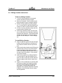
USER GUIDE
UGB011-0208
TrueBlend ™
Gravimetric Blender
Software Version V2.9.1
USER INSTRUCTIONS • About this operating manual • Warranty and liability • Layout of the manual • Meaning of safety
information Display conventions • Pictograms for safety and information Abbreviations • SAFETY • General • Designated
use • Sources of danger • Safety devices • Warning symbols on the unit • Information for the operator • Information for
operating and maintenance personnel • TECHNICAL SPECIFICATIONS • Manufacturer • Specifications • TRANSPORT AND
SETUP • Unpacking • Lifting • Setup • Positioning controller • Making connections • Stowing discharge chute
STRUCTURE AND FUNCTION • Structure of the unit • Brief description of the functional units • Layout of the material
hoppers • Operating modes • Gravimetric mode • Volumetric mode • Combined mode • COMMISSIONING • OPERATION
Switching on • Menu structure • Navigation • Starting and stopping the metering and mixing process • Switching off
Logging in/logging out • Commissioning • Mixing process • Component setup • GRAVICOLOR Setup • Working with recipes
Changing material for a component (also valid for all other components) • Checking total throughout • Creating reports
Co rpo r a te O f fic e : 72 4.584. 550 0 | I n s t ant Acc es s 2 4/7 ( Pa r ts an d Se rv ice ): 800 . 458. 196 0 | P a rts and Se rvic es : 814 .43 7.6 861
Copyright
© 2008 Conair
The information contained in these operating instructions, including any translation thereof, is the property of Conair and may not be reproduced or transmitted in
any form or by any means (electronic, mechanical, photocopying, recording or
otherwise, nor stored in any retrieval system of any nature for any purpose) without the express written authority of Conair
• To every person concerned with commissioning of the devices/systems it is
recommended to read thoroughly these operating instructions.
Conair accepts no responsibility or liability for damage or malfunction of the
equipment arising from non-observance of these operating instructions.
• To avoid errors and to ensure trouble-free operation, it is essential that
these operating instructions are read and understood by all personnel who
are to use the equipment.
• Should you have problems or difficulties with the equipment, please contact
your local Conair partner (see list attached).
• These operating instructions only apply to the equipment described below.
Manufacturing address:
The Conair Group, Inc.
455 Allegheny Blvd.
Franklin, PA 16323
USA
Conair Headquarters:
CE
The Conair Group, Inc.
Phone:
724.584.5500
200 West Kensinger Drive
Fax:
724.584.5299
Cranberry Township, PA 16066
www.conairgroup.com
Contents
TrueBlend™
Contents
1.0 User instructions................................................................................................ 7
1.1
1.2
1.3
1.4
1.5
About this operating manual.................................................................................... 7
Layout of the manual............................................................................................... 8
Meaning of safety information ................................................................................. 9
Pictograms for safety and information................................................................... 10
Abbreviations......................................................................................................... 10
2.0 Safety ................................................................................................................ 11
2.1
2.2
2.3
2.4
2.5
2.6
2.7
2.8
2.9
General.................................................................................................................. 11
Safety Hazards...................................................................................................... 11
Safety Features ..................................................................................................... 12
Designated use ..................................................................................................... 12
Sources of danger ................................................................................................. 14
Safety devices ....................................................................................................... 17
2.6.1 Position of safety devices........................................................................... 17
2.6.2 Detachable Material Hopper Procedure..................................................... 18
Warning symbols on the unit ................................................................................. 19
2.7.1 Position of warning symbols on the unit..................................................... 19
2.7.2 Meaning of warning symbols on the unit.................................................... 20
Information for the operator................................................................................... 20
2.8.1 Qualifications of personnel......................................................................... 20
Information for operating and maintenance personnel.......................................... 21
3.0 Technical specifications.................................................................................. 22
4.0 Transport and setup ........................................................................................ 33
4.1
4.2
4.3
4.4
4.5
2
Unpacking ............................................................................................................. 33
Lifting..................................................................................................................... 33
Setup ..................................................................................................................... 34
Positioning controller ............................................................................................. 34
Making connections............................................................................................... 35
4.5.1 Compressed air connection ....................................................................... 35
Edition: February 2008
TrueBlend™
Contents
4.5.2 Electrical connection .................................................................................. 35
4.5.3 Hopper loader connection (option)............................................................. 36
5.0 Structure and function .....................................................................................37
5.1 Structure of the unit............................................................................................... 37
5.2 Brief description of the functional units
(Item numbers refer to diagram on previous page) ........................................................ 38
5.3 Layout of the material hoppers ............................................................................. 38
5.3.1 For four component blenders..................................................................... 39
5.3.2 For six component blenders....................................................................... 39
5.4 Operating modes .................................................................................................. 40
5.4.1 Gravimetric mode – General...................................................................... 41
5.4.2 Gravimetric mode – Naturals Blend – All Naturals = 100% (extrusion) ..... 41
5.4.3 Volumetric mode ........................................................................................ 43
5.4.4 Combined mode......................................................................................... 43
6.0 Start-up..............................................................................................................43
7.0 Operation...........................................................................................................43
7.1
7.2
7.3
7.4
7.5
7.6
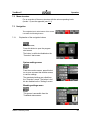
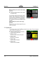
Switching on.......................................................................................................... 43
7.1.1 Switch on main switch................................................................................ 44
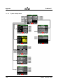
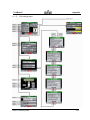
Menu structure ...................................................................................................... 45
Navigation ............................................................................................................. 45
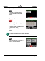
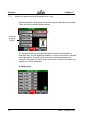
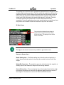
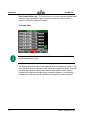
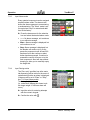
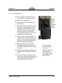
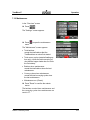
7.3.1 Explanation of the navigation buttons ........................................................ 45
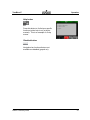
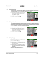
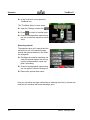
7.3.2 Explanation of keypad screens .................................................................. 48
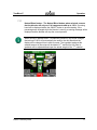
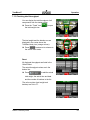
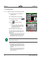
7.3.3 Explanation of additional screen icons....................................................... 49
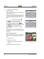
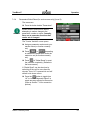
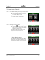
Starting and stopping the blending process .......................................................... 50
7.4.1 Starting blender process (with set values or factory setting) ..................... 50
7.4.2 Stopping the blending process................................................................... 50
7.4.3 Restarting after EMERGENCY STOP ....................................................... 51
Turning off the power ............................................................................................ 51
7.5.1 Stopping the blender at the end of a cycle................................................. 51
7.5.2 Switching off in emergency ........................................................................ 52
Logging in/logging out........................................................................................... 53
7.6.1 User levels and password input (for service users only!) (Level 3)............ 53
7.6.2 Changing password (for service users only!) (Level 3).............................. 53
7.6.3 Auto logout (for service users only!) (Level 3) ........................................... 54
7.6.4 Parameters/Global Reset (for service users only!) (Level 3) ..................... 55
Edition: February 2008
3
Contents
7.7
7.8
7.9
7.10
7.11
7.12
7.13
7.14
7.15
7.16
4
TrueBlend™
Start-up.................................................................................................................. 56
7.7.1 Checking functions in manual mode .......................................................... 56
7.7.2 Calibrating .................................................................................................. 60
7.7.3 Input TrueBlend Model/Name (for service users only!) (Level 3) ............... 65
7.7.4 Input TrueBlend name................................................................................ 66
7.7.5 Activating Batch Setting ............................................................................. 67
7.7.6 Advanced Operation Settings (Password level 3 only) .............................. 70
7.7.7 Natural Blend Button .................................................................................. 73
Blending process................................................................................................... 74
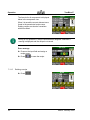
7.8.1 Assigning components – factory default setting......................................... 74
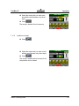
7.8.2 Example of a mixing process ..................................................................... 76
7.8.3 Typical dispense cycle based (7.8.2) settings............................................ 77
Component setup .................................................................................................. 78
7.9.1 Input of material percentages..................................................................... 79
7.9.2 Input of Material type.................................................................................. 79
7.9.3 Input Alarm mode....................................................................................... 80
7.9.4 Input Dosing retries .................................................................................... 80
TrueBlend Setup ................................................................................................... 81
7.10.1 Setting Operating mode ............................................................................. 81
7.10.2 Setting Weigh Bin Batch Weight ................................................................ 82
7.10.3 Setting Mixing time..................................................................................... 83
7.10.4 Setting the Interval time ............................................................................. 83
7.10.5 Setting Damping......................................................................................... 83
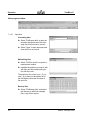
Working with recipes ............................................................................................. 84
7.11.1 Calling recipe status................................................................................... 84
7.11.2 Assigning an order number ........................................................................ 84
7.11.3 Save a new recipe...................................................................................... 85
7.11.4 Naming a recipe ......................................................................................... 85
7.11.5 Deleting a recipe ........................................................................................ 86
7.11.6 Load/view a recipe ..................................................................................... 87
Changing material in a blender component (also valid for all other components). 88
7.12.1 Detachable Material Hopper Procedure..................................................... 88
7.12.2 Manual cleaning: ........................................................................................ 89
7.12.3 Clean-out with optional drain chute with safety interlock ........................... 91
Checking total throughput ..................................................................................... 93
Creating reports..................................................................................................... 94
7.14.1 Reports for batches, shifts, recipes and scales.......................................... 94
7.14.2 Report generator – TrueBlend Reports...................................................... 95
7.14.3 Operation ................................................................................................... 96
System setup....................................................................................................... 100
Panel setup ......................................................................................................... 101
Edition: February 2008
TrueBlend™
Contents
7.17 System info ......................................................................................................... 102
7.18 Maintenance ....................................................................................................... 103
7.19 Hopper loaders (Optional)................................................................................... 105
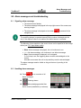
7.19.1 Go to Material loading (conveying) overview screen ............................... 105
7.19.2 Switching on hopper loaders.................................................................... 105
7.19.3 Changes to Loader Screen ...................................................................... 107
7.19.4 Loader Alarm Settings ............................................................................. 107
7.19.5 Settings .................................................................................................... 108
8.0 Alarm messages and troubleshooting..........................................................113
8.1
8.2
8.3
8.4
8.5
8.6
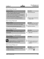
Signaling alarm message.................................................................................... 113
Handling alarm messages .................................................................................. 113
Deciphering Alarm Messages ............................................................................. 114
Alarm messages and correction ......................................................................... 114
Troubleshooting/Mechanics ................................................................................ 118
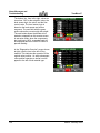
Diagnostic Overview Screens ............................................................................. 119
9.0 Maintenance and repair..................................................................................121
9.1
9.2
9.3
9.4
9.5
9.6
Safety.................................................................................................................. 121
9.1.1 Qualifications of personnel....................................................................... 121
9.1.2 9.1.2 Safety equipment ............................................................................ 121
9.1.3 9.1.3 Safety equipment ............................................................................ 121
Before starting work ............................................................................................ 122
9.2.1 Switch off unit/disconnect from compressed air supply ........................... 122
Inspections.......................................................................................................... 122
9.3.1 Checking EMERGENCY STOP function ................................................. 122
9.3.2 Testing safety interlock switch ................................................................. 122
9.3.3 Test the safety interlock switch as described in 6.7.1
Checking functions in manual mode. .................................................................. 122
Mixing chamber instructions ............................................................................... 123
Maintenance work............................................................................................... 124
9.5.1 Annual maintenance work........................................................................ 125
Repair work......................................................................................................... 127
9.6.1 Calibrate/adjust a sensor with no material present .................................. 127
9.6.2 Calibrate/adjust a sensor with no material present –
(This style material sensor used in units built after September 2007.) ............... 131
9.6.3 Replacing pneumatic cylinder on vertical dispense valve assembly........ 132
9.6.4 Load Cell Removal and Installation
for Trueblend models, TB045 and TB100 ........................................................... 133
Edition: February 2008
5
Contents
9.7
10.0
TrueBlend™
9.6.5 TrueBlend Weigh Bin Mount Installation and Adjustment
models TB45 and TB100..................................................................................... 136
9.6.6 Load Cell Removal and Installation
for Trueblend models, TB250, TB500 and TB900............................................... 139
9.6.7 Replacing controller ................................................................................. 143
Cleaning .............................................................................................................. 143
9.7.1 Cleaning material hopper and mixing chamber........................................ 143
Decommissioning and disposal ........................................................... 144
10.1 Decommissioning the unit ................................................................................... 144
10.2 Disposing of unit parts......................................................................................... 144
11.0
Appendix ................................................................................................ 145
11.1 Menu structure .................................................................................................... 145
11.1.1 Operating levels/password level .............................................................. 145
11.1.2 Menu overview/dosing unit....................................................................... 146
11.1.3 Menu overview/conveying........................................................................ 147
11.1.4 System settings menu.............................................................................. 148
11.1.5 Unit settings menu ................................................................................... 149
11.1.6 Conveyor settings menu .......................................................................... 150
11.1.7 Operating time menu................................................................................ 151
12.0
Appendix: Addendum for Retrofit Blenders........................................ 152
12.1 Retrofit Control Blender Start up Procedures...................................................... 152
13.0
Appendix ................................................................................................ 154
13.1 Blow off installation instruction sheet .................................................................. 154
14.0
Appendix ................................................................................................ 156
14.1 Replacing the TrueBlend Touch Screen Control................................................. 156
6
Edition: February 2008
TrueBlend™
User Instructions
1.0 User instructions
1.1
About this operating manual
This operating manual is a component of the TrueBlend Gravimetric blender.
It contains important instructions on the correct operative and maintenance of the
unit. Follow these instructions to avoid dangers, to prevent repair expenses and
downtime and to increase the service life of the unit.
The manual must be kept for referral with the unit at its place of use. The manual
must also accompany the unit if it is rented or sold.
It is directed to people who operate and repair the unit and must be read, understood and used by every person who is responsible for the following work with the
unit:
• Transport and setup,
• Operation,
• Maintenance and repair,
• Correction of faults,
• Decommissioning and disposal.
Take particular note of
• the chapter on,
• the warning notes in the various chapters.
Edition: February 2008
7
User Instructions
1.2
TrueBlend™
Layout of the manual
This manual is classified into several main parts:
• User information,
• Safety,
• Technical specifications,
• Transport and setup,
• Structure and function,
• Operation,
• Maintenance and repair,
• Decommissioning and disposal,
• Appendix (menu structure).
8
Edition: February 2008
TrueBlend™
1.3
User Instructions
Meaning of safety information
Safety instructions are placed before the work steps. Read the safety instructions
carefully before carrying out the subsequent operation.
If safety instructions are not followed, serious personal injury - possibly with fatal
results - and property and environmental damage may occur!
The safety instruction in this operating manual are indicated with a symbol. The
symbol contains a signal word indicating how serious the danger is.
A symbol with the word "DANGER" warns of an imminent danger to the
health and life of persons.
DANGER!
If these safety instructions are not observed serious or even fatal injuries
will be caused.
Î Always observe the directions for avoiding such dangers.
A symbol with the word "WARNING" warns of a possible dangerous situation for the health and life of persons.
WARNING!
CAUTION!
If these safety instructions are not observed serious or even fatal injuries
may be caused.
Î Always observe the directions for avoiding such dangers.
A symbol with the word "CAUTION" warns of a possible dangerous situation for the health and life of persons or of property and environmental damage.
If these safety instruction are not observed injury or property and environmental damage may occur.
Î Always observe the directions for avoiding such dangers.
Edition: February 2008
9
User Instructions
1.4
TrueBlend™
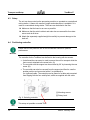
Pictograms for safety and information
In this operating manual you will find sections of text that a re identified by pictograms. The meaning of the pictograms is described below.
Pictogram for general identification of hazards. This pictogram occurs in connection with safety instructions (see 1.3 Meaning of safety information).
Pictogram for hand injury. This pictogram occurs in connection with safety
instructions (see 1.3 Meaning of safety information).
Pictogram for electric shock. This pictogram occurs in connection with safety
instructions (see 1.3 Meaning of safety information).
Pictogram information for identification of important instructions, additional
information and tips.
Pictogram for safety gloves that warns you to wear safety gloves.
1.5
Abbreviations
The following terms and abbreviations are used in this operating manual (in alphabetical order):
10
Abbreviation
Meaning
CAN
Controller Area Network
E-motor
Electric motor
LED
Light-emitting diode
PU
Polyurethane
Edition: February 2008
TrueBlend™
Safety
2.0 Safety
2.1
General
This chapter contains basic safety instructions for working with the gravimetric
batch blending unit.
Observe all the instructions for the operation and maintenance of the unit in this
chapter.
In addition, observe the warning notices that are placed before the action directions where the operating steps are described.
2.2
Safety Hazards
MIX BLADES
Mix blades are driven with substantial torque.
NEVER place your hand in the mix chamber unless power is completely disconnected.
SERIOUS INJURY may result.
ADDITIONAL MIX BLADE HAZARD
Over time, mix blades may become RAZOR SHARP.
Always be careful when TOUCHING or CLEANING these blades.
Check for sharp edges frequently.
Replace blade if a hazard exists.
VERTICAL VALVES
Vertical valves in hoppers SLAM CLOSED without warning.
They will injure your fingers.
ALWAYS keep fingers clear valve openings.
NEVER use your fingers to clear an obstruction.
NEVER use your fingers to move a sticking valve.
Edition: February 2008
11
Safety
TrueBlend™
SLIDE GATE/MIX CHAMBER
NEVER use your fingers to move a sticking slide gate under the mix chamber.
2.3
Safety Features
SAFETY INTERLOCK SWITCH
The ACCESS DOOR is equipped with a safety interlock switch that prevents
the mix motor from running and the slide valves from operating.
DO NOT defeat this safety switch
HOPPER FINGER GUARDS
Finger guards are fitted into each hopper compartment.
DO NOT reach through these guards.
DO NOT use your fingers to clear an obstruction below these guards.
DO NOT remove these guards.
2.4
Designated use
The TrueBlend gravimetric blender must be used exclusively for metering and
mixing free-flowing 1 plastic granulate and additives. A total of four different materials can be metered and mixed in the TB 45 and TB 100 models. Other models
for up to six different materials are available including the: TB 250, 500 and 900
model series.
The following must not be metered and mixed:
• Foods of all types (the unit does not meet the hygienic standards),
• Highly abrasive materials, such as stones, sand (increased wear of unit
components),
• Poorly free-flowing, sticky materials (materials only flow poorly, airtight seal
by the pneumatic cylinder is adversely affected),
• Liquids and powders (airtight seal by the pneumatic cylinder is not possible).
1
12
as per DIN ISO 3435
Edition: February 2008
TrueBlend™
Safety
Do not make any changes to the unit. Any changes may adversely affect the
safety of the unit.
Designated use includes following this operating manual and following the specified maintenance intervals and conditions.
Please contact Conair if you have any questions about the designated use of
the unit.
NOTE
Edition: February 2008
13
Safety
2.5
TrueBlend™
Sources of danger
The unit is manufactured to comply with the state of the art in technology and the
generally accepted rules of safety engineering. However, operation of the unit
may give rise to dangers for life and limb of the operator or third parties or damage to the unit or other property.
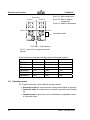
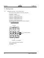
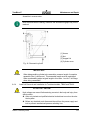
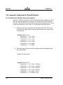
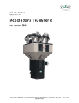
The unit has four sources of danger, which are shown in the figure below:
Fig. 1: Sources of danger
[1] Electrical system/power cabinet
[2] Pneumatic material seal at the outlet of the pneumatically operated vertical
valves
[3] Agitator in mixing chamber
[4] Pneumatic seal at the discharge slide gate
14
Edition: February 2008
TrueBlend™
Safety
The sources of danger and the consequences are shown in more detail below:
Danger source
Consequences
Electrical system
Fatal injury by electric shock!
High voltages can cause life-threatening currents
in the body and electric shock.
Î Allow only trained and qualified electrical technicians to work on the electrical system.
Î Before any electrical work disconnect the unit
from the power supply and lock to prevent unauthorized persons switching it on.
Pneumatic seal on
supply hoppers
Danger of injury by moving parts!
Mixer
Danger of injury by moving parts!
Vertically moving pneumatic cylinders can cause
crushing, impact and shearing injuries.
Î Do not reach into the pneumatic seal of the
supply hopper during normal operation and
during manual operation.
Rotating mixing blades can catch body parts and
pull them in and cause life-threatening crushing,
shearing and bone fracture injuries.
The edges of the mixing blades can be as sharp
as knives after extended operation.
Î Never reach into the mixing chamber while the
mixer is rotating.
Î Do not extend any objects into the movement
range of the mixer.
Î Do not disable the safety interlock switch.
Î Wear gloves when touching or cleaning the
stationary mixer.
Edition: February 2008
15
Safety
TrueBlend™
Danger source
Consequences
Pneumatic seal on the
discharge slide gate 2 at
bottom of mix chamber
Danger of injury by moving parts!
2
16
Horizontally moving pneumatic cylinders can
cause crushing, impact and shearing injuries and
bone fractures.
Î Do not reach into the pneumatic discharge
slide gate during normal operation and during
manual operation.
The pneumatic discharge slide gate is not installed if a manual slide gate is installed and the unit is
mounted directly on the injection molding machine.
Edition: February 2008
TrueBlend™
2.6
Safety
Safety devices
Safety devices protect your health and your life.
Do not operate the unit without effective safety devices.
DANGER OF INJURY!
WARNING!
2.6.1
The operator runs the risk of injury if the safety devices are not operating correctly.
Î Check that the safety devices function correctly after work has finished
(see 7.7.1 Testing the mix chamber safety interlock switch).
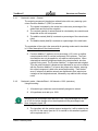
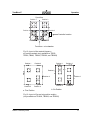
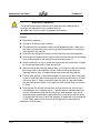
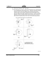
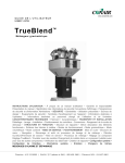
Position of safety devices
Electrical System/Power Cabinet
Fig. 2: Safety devices
[1] Finger guard
[2] Safety interlock switch (Mix chamber door)
[3] Main switch (=EMERGENCY STOP)
[4] Padlock
[5} Alarm beacon
[6] Alarm horn
Edition: February 2008
17
Safety
2.6.2
TrueBlend™
Safety device
Safety function
Safety guard
Prevents injury by crushing and impact at the pneumatic cylinder of the supply hopper.
Safety interlock
switch
Stops the mixer motor when the main door is opened.
EMERGENCY STOP
switch
Stops all movement of the machine.
Padlock
Locks the switch to prevent unauthorized persons
switching it on.
Detachable Material Hopper Procedure
Detachable material hopper for TB45 (4 bins) TB100 (2 bins) and
TB250R-4 (2 bins) models.
NOTE
All detachable material hoppers on the above referenced models are held in place
with a captive retainer (screw) held in the hopper support frame. The retainer
stabilizes the detachable hopper when mounted in the blender support frame from
forces exerted on the hopper by resin weight and various types of automatic
loading/receiving device(s) during normal vibration from the process. There is a
separate retainer for each detachable hopper.
When removing any of these detachable hoppers for cleaning or material
changeover; first, remove the automatic loading/receiving device; then use the
proper hex head socket or screwdriver and back out the captive retainer. Hopper
can then be removed.
Upon re-insertion of the detachable hopper, it is very important to re-anchor
the respective hopper(s) using the captive retainer to provide stability
during normal operation of the blender. Once the hoppers have been placed
and anchored, the respective loading / receiving devices can be mounted.
18
Edition: February 2008
TrueBlend™
2.7
Safety
Warning symbols on the unit
The instructional, warning and prohibition signs on the unit are a component of
the operating manual. Observe and follow these signs in the same way as with
the manual. Keep the signs clean and legible and never remove them, paint over
them or stick other signs over them.
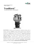
2.7.1
Position of warning symbols on the unit
Fig. 3: Warning symbols on the unit
Edition: February 2008
19
Safety
2.7.2
TrueBlend™
Meaning of warning symbols on the unit
Symbol
2.8
Meaning
Explanation
Warning of hazardous electrical voltage
Only electrical technicians may
work on the electrical system.
Warning of injury to hands
Do not reach into the pneumatic
seal on the supply hoppers and
the discharge slide gate during
operation. Never touch the mixer
blades.
Information for the operator
The operator is responsible for the designated use of the unit.
2.8.1
Qualifications of personnel
The operator is responsible for ensuring that the personnel are qualified for the
requirements of their tasks.
• The machine must only be operated by trained and qualified person authorized by the operator.
• Personnel, who are apprentices, are in training or instruction may only work
on the machine under the supervision of an experienced person.
DANGER OF INJURY!
WARNING!
20
Improper operation and maintenance by insufficiently qualified personnel
may lead to incalculable risks with negative results for persons, machine and
the environment.
Î Only qualified and authorized technicians may operate the machine and
carry out repair and maintenance work.
Edition: February 2008
TrueBlend™
2.9
Safety
Information for operating and maintenance personnel
Persons who are required to operate and maintain the unit must read and understand the operating manual, particularly the section on safety, before starting
work.
The following safety instructions are particularly important for avoiding personal
injury and property damage:
• Observe all safety and danger information on the unit.
• Keep all unauthorized people clear of the unit.
• Make sure that no people are in the danger zone every time before starting
the unit.
• Keep the operating station clear of tools, equipment and other objects. Do
not place tools or other objects on the unit. Vibration can cause them fall off
the unit and injure persons and/or cause property damage.
• Keep the unit and work area clean and make sure that granulate does not
accumulate on the floor. It may cause people to slip and injure themselves.
• Wear work gloves when working on the stationary mixer. Work gloves protect hands and fingers from being cut.
• The local safety and accident prevention regulation always apply for work
with the unit.
Edition: February 2008
21
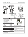
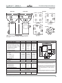
T r u e Bl e nd™
Technical Specifications
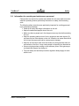
TB45-4
TPBM024-0207
Front view
Side view
C
1
Top view
Position 1
Position 2
‡Position 4
‡Position 3
B
3
4
4
A
Control
Drain chute
D
Purchase the optional
material drain chute
that readily installs to the
chassis opening of the
blender for fast and
simple cleanout.
Maximum loader sizes
8 inch loaders
22
30.90 {785}
23.63 {600}
25.78 {655}
8.25 {209.6}
9.25 {235.0}
4.75 {120.6}
Mixing chamber access door this side of the interface.
7-7/8 {200}
1-25/32
diameter
{45}
1-7/16
{37}
7-15/32 {190}
5 {127}
3-3/4
{95}
1.0 {450}
200 {91}
0.2 {5.7}
0.2 {5.7}
4
4
2 - (40 mm)
2 - (20 mm)
MOUNTING INTERFACE
Dimensions shown
in inches and
{mm}.
1-1/4
{31}
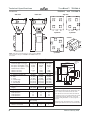
TB45-4
5 {127}
MODELS
Performance characteristics
Batch size lb {g}
Maximum throughput rate lb/hr {kg/hr}*
Bin capacity - main ingredient ft3 {liter}
Bin capacity - minor ingredient ft3 {liter}
Maximum number of materials
Number of vertical discharge valves
Number/(size) of major bin valves
Number/(size) of minor bin valves
Dimensions inches {mm}
A - Height above mounting plate†
B - Width
C - Depth
D - Control height
E - Control width
F - Control depth
Weight lbs {kg}
Installed
Shipping
Voltage total amps
115V/1 phase/60 hz
230V/1 phase/50 hz
Compressed air requirements
Discharge valves
E
F
3-15/16
{100}
Mounting bolt hole size (4 holes) 7/16 inch {11.0 mm}.
Predrilled 5 x 5 mounting pattern as standard.
SPECIFICATION NOTES
* Maximum throughput rates are based on 35 lb/ft3 pel-
75 {34}
125 {57}
letized material and using all standard valve sizes. Use
of reducer inserts will lower the rate shown.
† The optional flow control valve will mount inside the
1.0
0.5
90 psi @ 0.2 ft3/min {6 bars
@ 0.09 liters/sec}; 1/4 in. NPT fitting
Number of loaders - 4
chassis in the space of the manual slide valve. Conair
recommends using the optional flow control valve when
mounting the blender on a stand, surge bin or hopper.
‡ Hopper positions three and four are supplied with
eight inch cover plates as standard.
Specifications may change without notice consult with a
Conair representative for the most current information.
Edition: February 2008
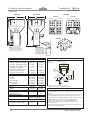
Technical Specifications
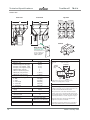
TrueBlend™ TB100-4
TPBM025-0207
Side view
Front view
Top view
B
C
Position 2
Position 1
1
4
4
3
A
‡Position 4
‡Position 3
Control
Drain chute
Purchase the optional
material drain chute
that readily installs to the
chassis opening of the
blender for fast and
simple cleanout.
B - Width
C - Depth
D - Control height
E - Control width
F - Control depth
Weight lbs {kg}
Installed
Shipping
Voltage total amps
115V/1 phase/60 hz
230V/1 phase/50 hz
Compressed air requirements
Discharge valves
Maximum loader sizes
8 inch loaders
12 inch loaders
Edition: February 2008
45.0 {1145}
30.25 {769}
31.85 {809}
8.25 {209.6}
9.25 {235.0}
4.75 {120.6}
160 {72}
270 {122}
3.0
1.5
90 psi @ 0.2 ft3/min {6 bars
@ 0.09 liters/sec}; 1/4 in. NPT fitting
Mixing chamber access door this side of the interface.
10-1/4 {260}
2-5/32
diameter
{55}
1-1/8
{28}
10-7/32 {260}
8 {203}
5-1/8
{130}
2.2 {1000}
450 {204}
0.6 {17}
0.3 {8}
4
4
2 - (60 mm)
2 - (20 mm)
MOUNTING INTERFACE
Dimensions shown
in inches and
{mm}.
8 {203}
TB100-4
E
F
1-1/8
{28}
MODELS
Performance characteristics
Batch size lb {g}
Maximum throughput rate lb/hr {kg/hr}*
Bin capacity - main ingredient ft3 {liter}
Bin capacity - minor ingredient ft3 {liter}
Maximum number of materials
Number of vertical discharge valves
Number/(size) of major bin valves
Number/(size) of minor bin valves
Dimensions inches {mm}
A - Height above mounting plate†
D
5-1/8
{130}
Mounting bolt hole size (4 holes) 9/16 inch {14.0 mm}.
Predrilled 8 x 8 mounting pattern as standard.
SPECIFICATION NOTES
* Maximum throughput rates are based on 35 lb/ft3
pelletized material and using all standard valve sizes.
Use of reducer inserts will lower the rate shown.
† The optional flow control valve will mount inside the
chassis in the space of the manual slide valve. Conair
recommends using the optional flow control valve when
mounting the blender on a stand, surge bin or hopper.
‡ Hopper position two is supplied with a 12-8 adapter
and eight inch cover plate as standard.
Specifications may change without notice consult with a
Conair representative for the most current information.
Number of loaders - 2
Number of loaders - 2
23
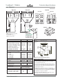
Technical Specifications
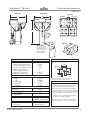
T r u e Bl e nd™
TPBS026/0207
TB250-4
and TB250-6
Front view
Side view
Top view
B
C
4 position
Position 2
Position 1
1
Position 2
Position 1
3
‡Position 3
‡Position 6
4
6 position
A
‡Position 4
‡Position 3
‡Position 4
‡Position 5
Control
B - Width
C - Depth
D - Control height
E - Control width
F - Control depth
Weight lbs {kg}
Installed
Shipping
Voltage total amps
115V/1 phase/60 hz
230V/1 phase/50 hz
Compressed air requirements
Discharge valves
Maximum loader sizes
15 inch loaders - number of loaders 8 inch loaders- number of loaders -
D
Purchase the optional
material drain chute
that readily installs to the
chassis opening of the
blender for fast and
simple cleanout.
5.5 {2500}
1000 {454}
1.6 {45.3}
1.6 {45.3}
4
4
2 - (60 mm)
2 - (30 mm)
5.5 {2500}
800 {363}
2.7 {76.4}
1.4 {39.6}
6
6
2 - (60 mm)
4 - (30 mm)
57.50 {1461}
36.50 {926}
40.83 {1037}
8.25 {209.6}
9.25 {235.0}
4.75 {120.6}
63.0 {1600}
40.13 {1026}
42.67 {1084}
8.25 {209.6}
9.25 {235.0}
4.75 {120.6}
320 {145}
440 {200}
400 {182}
520 {236}
6.3
3.2
6.3
3.2
90 psi @ 0.2 ft3/min {6 bars @ 0.09
liters/sec}; 1/4 in. NPT fitting
4
NA
2
4
MOUNTING INTERFACE
Mixing chamber access door this side of the interface.
Dimensions
shown in
inches and {mm}.
16-5/32 {410}
12 {305}
8 {203}
3-5/32
diameter
{80}
2-1/16
{53}
16-5/32 {410}
TB250-6
8-1/16
{205}
TB250-4
E
F
2-1/16
{53}
MODELS
Performance characteristics
Batch size lb {g}
Maximum throughput rate lb/hr {kg/hr}*
Bin capacity - main ingredient ft3 {liter}
Bin capacity - minor ingredient ft3 {liter}
Maximum number of materials
Number of vertical discharge valves
Number/(size) of major bin valves
Number/(size) of minor bin valves
Dimensions inches {mm}
A - Height above mounting plate†
Drain chute
4-1/16
{103}
NOTE: Side and front view
drawings are model TB250-4.
The bin positions change for a
TB250-6 see the top view.
8-1/16
{205}
4-1/16
{103}
Mounting bolt hole size (8 holes) 9/16 inch {14.0 mm}.
Predrilled 8 x 8 and 12 X 12 mounting pattern as standard.
SPECIFICATION NOTES
* Maximum throughput rates are based on 35 lb/ft3 pelletized material and using all standard valve sizes. Use of
reducer inserts will lower the rate shown.
† The optional flow control valve will mount inside the
chassis in the space of the manual slide valve. Conair
recommends using the optional flow control valve when
mounting the blender on a stand, surge bin or hopper.
‡ TB250-4 hopper positions two and four are supplied with
12-8 adapters with eight inch cover plates as standard.
TB250-6 hopper position two is supplied with a 12-8
adapter with an eight inch cover.
Specifications may change without notice consult with a
Conair representative for the most current information.
24
Edition: February 2008
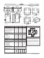
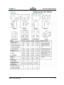
T r u e Bl e nd™
TB250-R-4
Technical Specifications
TPBS035-0207
Side view
Front view
C
B
Top view
4 position
1
‡Position 2
Position 1
4
3
A
‡Position 4
‡Position 3
Control
Drain chute
Purchase the optional
material drain chute
that readily installs to the
chassis opening of the
blender for fast and
simple cleanout.
Maximum loader sizes
15 inch loaders - number of loaders 8 inch loaders- number of loaders -
Edition: February 2008
57.50 {1461}
36.50 {926}
38.88 {988}
8.25 {209.6}
9.25 {235.0}
4.75 {120.6}
280
400
6.3
3.2
90 psi @ 0.2 ft3/min
{6 bars @ 0.09 liters/sec};
1/4 in. NPT fitting
2
2
Mixing chamber access door this side of the interface.
16-5/32 {410}
12 {305}
3-5/32
diameter
{80}
2-1/16
{53}
16-5/32 {410}
8 {203}
8-1/16
{205}
5.5 {2500}
800 {363}
1.6 {45.3}
0.3 {8}
4
4
2 - (60 mm)
2 - (20 mm)
MOUNTING INTERFACE
Dimensions
shown in
inches and {mm}.
2-1/16
{53}
TB250R-4
E
F
4-1/16
{103}
MODELS
Performance characteristics
Batch size lb {g}
Maximum throughput rate lb/hr {kg/hr}*
Bin capacity - main ingredient ft3 {liter}
Bin capacity - minor ingredient ft3 {liter}
Maximum number of materials
Number of vertical discharge valves
Number/(size) of major bin valves
Number/(size) of minor bin valves (removable)
Dimensions inches {mm}
A - Height above mounting plate†
B - Width
C - Depth
D - Control height
E - Control width
F - Control depth
Weight lbs {kg}
Installed
Shipping
Voltage total amps
115V/1 phase/60 hz
230V/1 phase/50 hz
Compressed air requirements
Discharge valves
D
8-1/16
{205}
4-1/16
{103}
Mounting bolt hole size (8 holes) 9/16 inch {14.0 mm}.
Predrilled 8 x 8 and 12 X 12 mounting pattern as standard.
SPECIFICATION NOTES
* Maximum throughput rates are based on 35 lb/ft3 pelletized material
and using all standard valve sizes. Use of reducer inserts will lower
the rate shown.
† The optional flow control valve will mount inside the chassis in the
space of the manual slide valve. Conair recommends using the
optional flow control valve when mounting the blender on a stand,
surge bin or hopper.
‡ TB250R-4 hopper position two is supplied with a 12-8 adapter with
an eight inch cover plate as standard. Position three and four are
supplied with hand-fill lids.
Specifications may change without notice consult with a Conair representative for the most current information.
25
Technical Specifications
TrueBlend™ TB500-4
and TB500-6
TPBS027-0207
Front view
Side view
Top view
B
C
4 position
Position 1
1
4
6 position
Position 1
Position 2
‡Position 5
‡Position 4
Position 2
3
‡Position 6
‡Position 3
A
‡Position 3
‡Position 4
Control
D
Drain chute
Maximum loader sizes
15 inch loaders - number of loaders 8 inch loaders - number of loaders -
26
11 {5000}
1550 {703}
2.7 {76.4}
2.7 {76.4}
4
4
2 - (100/60 mm)
2 - (30 mm)
11 {5000}
1200 {544}
2.7 {76.4}
1.35 {38.2}
6
6
2 - (100/60 mm)
4 - (30 mm)
63.00 {1600}
40.13 {1026}
43.00 {1092}
8.25 {209.6}
9.25 {235.0}
4.75 {120.6}
63.00 {1600}
40.13 {1026}
43.00 {1092}
8.25 {209.6}
9.25 {235.0}
4.75 {120.6}
400 {182}
520 {236}
400 {182}
520 {236}
6.3
3.2
6.3
3.2
90 psi @ 0.2 ft3/min {6 bars @ 0.09
liters/sec}; 1/4 in. NPT fitting
4
NA
2
4
MOUNTING INTERFACE
Dimensions
shown in
inches and {mm}.
Mixing chamber access door - this
side of the interface.
16-5/32 {410}
12 {305}
8 {203}
3-5/32
diameter
{80}
2-1/16
{53}
16-5/32 {410}
TB500-6
2-1/16
{53}
TB500-4
4-1/16
{103}
MODELS
Performance characteristics
Batch size lb {g}
Maximum throughput rate lb/hr {kg/hr}*
Bin capacity - main ingredient ft3 {liter}
Bin capacity - minor ingredient ft3 {liter}
Maximum number of materials
Number of vertical discharge valves
Number/(size) of major bin valves
Number/(size) of minor bin valves
Dimensions inches {mm}
A - Height above mounting plate†
B - Width
C - Depth
D - Control height
E - Control width
F - Control depth
Weight lbs {kg}
Installed
Shipping
Voltage total amps
115V/1 phase/60 hz
230V/1 phase/50 hz
Compressed air requirements
Discharge valves
E
F
Purchase the optional
material drain chute
that readily installs to
the chassis opening of
the blender for fast
and simple cleanout.
8-1/16
{205}
NOTE: Side and front view
drawings are model TB500-4.
The bin positions change for a
TB500-6, see the top view.
8-1/16
{205}
4-1/16
{103}
Mounting bolt hole size (8 holes) 9/16 inch {14.0 mm}.
Predrilled 8 x 8 and 12 X 12 mounting pattern as standard.
SPECIFICATION NOTES
* Maximum throughput rates are based on 35 lb/ft3 pelletized material and
using all standard valve sizes. Use of reducer inserts will lower the rate
shown.
† The optional flow control valve will mount inside the chassis in the space
of the manual slide valve. Conair recommends using the optional flow
control valve when mounting the blender on a stand, surge bin or hopper.
‡ TB500-4 hopper positions three and four are supplied with 12-8
adapters with 8 inch cover plates as standard. TB500-6 hopper
position two is supplied with a 12-8 adapter and an 8 inch cover
plate as standard.
Specifications may change without notice, consult with a Conair representative for the most current information.
Edition: February 2008
T r u e Bl e nd™
and
Technical Specifications
TB900-4
TB900-6
TPBS028-0207
Side view
Top view
Front view
B
C
4 position
Position 1
6
5
Position 2
Position 2
‡Position 5
‡Position 4
4
‡Position 3
‡Position 6
1
6 position
Position 1
A
‡Position 4
‡Position 3
Control
D
Drain chute
Maximum loader sizes
20 inch loaders - number of loaders
15 inch loaders - number of loaders
8 inch loaders - number of loaders
Edition: February 2008
19.8 {9000}
3500 {1588}
4.4 {124.6}
4.4 {124.6}
4
4
2 - (100 mm)
2 - (60 mm)
19.8 {9000}
2800 {1270}
4.4 {124.6}
2.2 {62.3}
6
6
2 - (100 mm)
4 - (60 mm)
74.75 {1896}
48.5 {1229}
51.0 {1296}
8.25 {209.6}
9.25 {235.0}
4.75 {120.6}
74,75 {1896}
48.5 {1229}
51.0 {1296}
8.25 {209.6}
9.25 {235.0}
4.75 {120.6}
550 {249}
700 {318}
550 {249}
700 {318}
6.3
3.2
6.3
3.2
90 psi @ 0.2 ft3/min {6 bars @ 0.09
liters/sec}; 1/4 in. NPT fitting
4
NA
NA
2
2
2
MOUNTING INTERFACE
Dimensions
shown in inches
and {mm}.
Mixing chamber access door this side of the interface.
19-11/16 {500}
16 {406}
8 {203}
3-15/16
diameter
{100}
9-15/16 {252}
TB900-6
1-15/16
{49}
TB900-4
5-15/16
{151}
MODELS
Performance characteristics
Batch size lb {g}
Maximum throughput rate lb/hr {kg/hr}*
Bin capacity - main ingredient ft3 {liter}
Bin capacity - minor ingredient ft3 {liter}
Maximum number of materials
Number of vertical discharge valves
Number/(size) of major bin valves
Number/(size) of minor bin valves
Dimensions inches {mm}
A - Height above mounting plate†
B - Width
C - Depth
D - Control height
E - Control width
F - Control depth
Weight lbs {kg}
Installed
Shipping
Voltage total amps
115V/1 phase/60 hz
230V/1 phase/50 hz
Compressed air requirements
Discharge valves
E
F
Purchase the optional
material drain chute
that readily installs to
the chassis opening of
the blender for fast
and simple cleanout.
1-27/32
{47}
19-7/8 {505}
NOTE: Side and front view drawings
are model TB900-6.
The bin positions change for a
TB900-4, see the top view.
9-27/32
{250}
5-27/32
{148}
Mounting bolt hole size (8 holes) 9/16 inch {14.0 mm}.
Predrilled 8 x 8 and 16 X 16 mounting pattern as standard.
SPECIFICATION NOTES
* Maximum throughput rates are based on 35 lb/ft3 pelletized
material and using all standard valve sizes. Use of reducer
inserts will lower the rate shown.
† The optional flow control valve will mount inside the chassis in
the space of the manual slide valve. Conair recommends using
the optional flow control valve when mounting the blender on a
stand, surge bin or hopper.
‡ TB900-4 hopper positions three and four are supplied with
12-8 adapters with eight inch cover plates as standard. TB900-6
hopper positions three and six are supplied with 12-8 adapters
and eight inch cover plates as standard.
Specifications may change without notice, consult with a Conair
representative for the most current information.
27
Technical Specifications
T r u e Bl e nd™
TB1800-5,
Side view
C
6
Front view
B
5
and
TB1800-4
TB1800-6
Top view
5
4
1
2
1
4
3
5
2
3
A
4
front
front
4 position
5 position
Control
1
2
6
D
3
5
NOTE: Side and front view drawings are shown for model TB1800-6.
The bin positions change for a TB1800-4 and TB1800-5 models, see
the top view.
front
6 position
40 {18000}
6000 {2722}
6 {170}
6 {170}
4
4 (5X5)
0
40 {18000}
5500 {2495}
6 {170}
4 {113}
5
3 (5X5)
2 (2X5)
40 {18000}
4800 {2177}
6 {170}
4 {113}
6
2 (5X5)
4 (2X5)
94.4 {2397.8}
53.0 {1346.2}
53.0 {1346.2}
8.25 {209.6}
9.25 {235.0}
4.75 {120.6}
94.4 {2397.8}
53.0 {1346.2}
53.0 {1346.2}
8.25 {209.6}
9.25 {235.0}
4.75 {120.6}
94.4 {2397.8}
53.0 {1346.2}
53.0 {1346.2}
8.25 {209.6}
9.25 {235.0}
4.75 {120.6}
1465 {665}
1715 {778}
1498 {679}
1748 {793}
1532 {695}
1782 {808}
11.3
11.3
7.5
5.0
4.5
3.9
11.3
11.3
7.5
5.0
4.5
3.9
11.3
11.3
7.5
5.0
4.5
3.9
MOUNTING INTERFACE
Dimensions
shown in inches
and {mm}.
30 {762.0}
27 {685.8}
15 {381.0}
30 {762.0}
TB1800-6
27 {685.8}
15 {381.0}
TB1800-5
Ø6
{Ø152.4}
24 {609.6}
TB1800-4
8 {203.2}
Voltage total amps
220V/1 phase/50 hz
220V/1 phase/60 hz
240V/3 phase/60 hz
400V/3 phase/50 hz
480V/3 phase/60 hz
575V/3 phase/60 hz
Compressed air requirements
E
15 {381.0}
MODELS
Performance characteristics
Batch size lbs {g} (grams or kilograms)
Maximum throughput lbs/hr {kg/hr}*
Bin capacity - main ingredient ft3 {liter}
Bin capacity - minor ingredient ft3 {liter}
Maximum number of materials
Number of major valves
Number of minor valves
Dimensions inches {mm}
A - Height above mounting plate
B - Width
C - Depth
D - Controller height
E - Controller width
F - Controller depth
Weight lbs {kg}
Installed
Shipping
F
4
8 {203.2}
15 {381.0}
16 {406.4}
SPECIFICATION NOTES
* Maximum throughput rates are based on 35 lb/ft3
pelletized material and using all standard valve sizes.
Use of reducer inserts will lower the rate shown.
The optional flow control valve will mount inside the
chassis in the space of the manual slide valve. Conair
recommends using the optional flow control valve
when mounting the blender on a stand, surge bin or
hopper.
Specifications may change without notice, consult with a
Conair representative for the most current information.
0.3 ft3/min @ 90 psi {6 bars @ 0.14 liters/sec}
3/8 in. NPT fitting
Maximum loader sizes
4 DL25
2 DL25 2 DL15
2 DL25 2 AR10
4 DL20
28
3 DL25
3 DL25
2 DL15 2 DL25
2 AR10 2 DL25
4 DL20
4 DL20
4 DL15
4 AR10
2 DL15
2 AR10
Edition: February 2008
TrueBlend™ TB2500-4
Technical Specifications
TB2500-5 and TB2500-6
TPBS032-0706
Side view
Front view
C
B
6
Top view
1
2
1
4
3
5
2
4
5
5
3
4
front
A
front
4 position
5 position
1
2
Control
6
D
3
5
4
F
E
front
6 position
55 {25000}
9000 {4082}
10 {283}
10 {283}
4
4 (6X6)
0
55 {25000}
8000 {3629}
10 {283}
5 {142}
5
3 (6X6)
2 (2X6)
55 {25000}
7000 {3175}
10 {283}
5 {142}
6
2 (6X6)
4 (2X6)
111.5 {2832.1}
72 {1828.0}
72 {1828.0}
8.25 {209.6}
9.25 {235.0}
4.75 {120.6}
111.5 {2832.1}
72 {1828.0}
72 {1828.0}
8.25 {209.6}
9.25 {235.0}
4.75 {120.6}
111.5 {2832.1}
72 {1828.0}
72 {1828.0}
8.25 {209.6}
9.25 {235.0}
4.75 {120.6}
2483 {1126}
2783 {1262}
2531 {1148}
2831 {1080}
2580 {1170}
2880 {1306}
10.3
7.7
6.4
5.6
10.3
7.7
6.4
5.6
10.3
7.7
6.4
5.6
Maximum loader sizes
Edition: February 2008
Dimensions
shown in
inches and
{mm}.
38 {965.2}
35 {889.0}
19 {482.6}
Ø8
{Ø203.2}
10 {252.7}
15 {381.0}
20 {508.0}
SPECIFICATION NOTES
* Maximum throughput rates are based on 35 lb/ft3
0.3 ft3/min @ 90 psi {6 bars @ 0.14 liters/sec}
3/8 in. NPT fitting
Number of 25 inch loaders
MOUNTING INTERFACE
35 {889.0}
19 {482.6}
TB2500-6
20 {508.0}
TB2500-5
10 {252.7}
Voltage total amps
240V/3 phase/60 hz
400V/3 phase/50 hz
480V/3 phase/60 hz
575V/3 phase/60 hz
Compressed air requirements
TB2500-4
15 {381.0}
MODELS
Performance characteristics
Batch size lbs {g} (grams or kilograms)
Maximum throughput lbs/hr {kg/hr}*
Bin capacity - main ingredient ft3 {liter}
Bin capacity - minor ingredient ft3 {liter}
Maximum number of materials
Number of major valves
Number of minor valves
Dimensions inches {mm}
A - Height above mounting plate
B - Width
C - Depth
D - Controller height
E - Controller width
F - Controller depth
Weight lbs {kg}
Installed
Shipping
38 {965.2}
NOTE: Side and front view drawings are shown for model TB2500-6.
The bin positions change for a TB2500-4 and TB2500-5 models, see
the top view.
4
5
pelletized material and using all standard valve sizes.
Use of reducer inserts will lower the rate shown.
The optional flow control valve will mount inside the
chassis in the space of the manual slide valve. Conair
recommends using the optional flow control valve
when mounting the blender on a stand, surge bin or
hopper.
Specifications may change without notice, consult with
a Conair representative for the most current information.
6
29
Technical Specifications
TB3500-5,
TPBS033-0706
Side view
B
5
and
TB3500-6
Top view
Front view
C
6
TB3500-4
T r u e Bl e nd™
1
2
1
4
3
5
2
4
5
3
4
A
front
front
4 position
5 position
Control
1
2
6
D
3
5
E
F
4
front
5 position
77 {35000}
12000 {5443}
18 {510}
18 {510}
4
4 (6X6)
0
77 {35000}
11000 {4990}
18 {510}
9 {255}
5
3 (6X6)
2 (2X6)
77 {35000}
10000 {4536}
18 {510}
9 {255}
6
2 (6X6)
4 (2X6)
156 {3962}
72 {1828}
72 {1828}
8.25 {209.6}
9.25 {235.0}
4.75 {120.6}
156 {3962}
72 {1828}
72 {1828}
8.25 {209.6}
9.25 {235.0}
4.75 {120.6}
156 {3962}
72 {1828}
72 {1828}
8.25 {209.6}
9.25 {235.0}
4.75 {120.6}
2982 {1353}
3282 {1489}
3049 {1383}
3349 {1519}
3115 {1413}
3415 {1549}
10.3
7.7
6.4
5.6
10.3
7.7
6.4
5.6
10.3
7.7
6.4
5.6
Maximum loader sizes
30
Dimensions
shown in
inches and
{mm}.
38 {965.2}
35 {889.0}
19 {482.6}
Ø8
{Ø203.2}
10 {252.7}
15 {381.0}
20 {508.0}
SPECIFICATION NOTES
* Maximum throughput rates are based on 35 lb/ft3
0.3 ft3/min @ 90 psi {6 bars @ 0.14 liters/sec}
3/8 in. NPT fitting
Number of 25 inch loaders
MOUNTING INTERFACE
35 {889.0}
19 {482.6}
TB3500-6
20 {508.0}
TB3500-5
10 {252.7}
Voltage total amps
240V/3 phase/60 hz
400V/3 phase/50 hz
480V/3 phase/60 hz
575V/3 phase/60 hz
Compressed air requirements
TB3500-4
15 {381.0}
MODELS
Performance characteristics
Batch size lbs {g}
Maximum throughput lbs/hr {kg/hr}*
Bin capacity - main ingredient ft3 {liter}
Bin capacity - minor ingredient ft3 {liter}
Maximum number of materials
Number of major valves
Number of minor valves
Dimensions inches {mm}
A - Height above mounting plate
B - Width
C - Depth
D - Controller height
E - Controller width
F - Controller depth
Weight lbs {kg}
Installed
Shipping
38 {965.2}
NOTE: Side and front view drawings are shown for model TB3500-6.
The bin positions change for a TB3500-4 and TB3500-5 models, see
the top view.
4
5
pelletized material and using all standard valve sizes.
Use of reducer inserts will lower the rate shown.
The optional flow control valve will mount inside the
chassis in the space of the manual slide valve. Conair
recommends using the optional flow control valve
when mounting the blender on a stand, surge bin or
hopper.
Specifications may change without notice, consult with
a Conair representative for the most current information.
6
Edition: February 2008
TrueBlend™
Edition: February 2008
Technical Specifications
31
Technical Specifications
32
TrueBlend™
Edition: February 2008
TrueBlend™
Transport and Setup
4.0 Transport and setup
4.1
Unpacking
MATERIAL DAMAGE!
CAUTION!
4.2
Forces that are exerted on the load cell from outside when attaching and removing the weigh bin load cell may damage the very sensitive load cell.
Î Do not use excessive force on the load cell.
Lifting
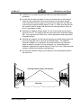
DANGER OF INJURY!
WARNING!
If the weight is unevenly distributed, the mixing unit may tip and injure people
when it is lifted.
Î Use only the lifting lug provided to lift the mixing unit.
Fig. 4: Lifting unit
Edition: February 2008
33
Transport and Setup
4.3
TrueBlend™
Setup
The unit can be mounted on the processing machine or operated as a centralized
mixing station. A frame with reservoir hopper and exhaust box is available if it is
used as a centralized mixing station. The frame can be bolted to the floor.
Î Make sure that the base is as even as possible.
Î Make sure that the switch cabinet and main door are accessible for maintenance work at all times.
Î Attach the separately supplied weigh bin carefully to prevent damage to the
load cell.
4.4
Positioning controller
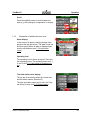
Please remove the protective film on the touchscreen control for optimum
performance
IMPORTANT
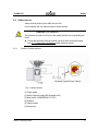
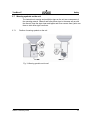
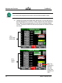
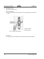
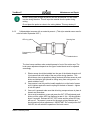
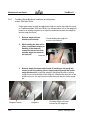
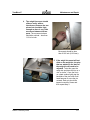
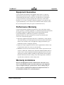
The controller for the TrueBlend can be fixed to the housing with two screws.
• As delivered the rear screw is used to secure the unit for transport while the
front screw is attached to the screw hole. (A)
• The controller with the support can be swiveled by 90° by loosening the rear
screw. (B)
• The controller can also be removed from the support and fixed to a wall or
another position and connected with a 2 m (standard) or
6 m (optional) cable. The controller can be placed on a table and prevented
from slipping with the four antislip feet, which are supplied with the cable.
[1] Mounting screws
[2] Rotary knob
Fig. 5: Swiveling controller
This setup not possible on model TB45
NOTE
34
Edition: February 2008
TrueBlend™
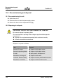
4.5
Transport and Setup
Making connections
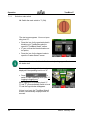
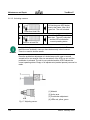
4.5.1
Compressed air connection
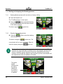
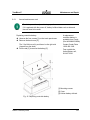
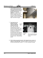
Î Connect the air hose [1] to the compressed air connection of the unit [2].
The operating pressure must be at least 0.6 MPa (87.0 psi) (6 bar).
Î Check the operating pressure with the manometer [3] and if it is different set it
to 0.6 MPa.
[1] Air hose
[2] Compressed air connection
[3] Manometer
Fig. 6: Connecting compressed air
NOTE
4.5.2
No additional compressed air consumers may be connected to the unit, because this may reduce the operating pressure. If the operating pressure is
less than 0.6 MPa the loading precision may be affected.
Electrical connection
Î Connect the gravimetric batch blending unit to the mains power-supply system.
Î Check that the unit functions after assembly (see 7.7 Startup).
NOTE
Electrical supply must be a clean power source with nothing else on the circuit (for example self-loading loaders.) The unit must be grounded to a lug by
the sensor on the back of the unit.
Edition: February 2008
35
Transport and Setup
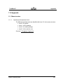
4.5.3
TrueBlend™
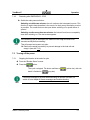
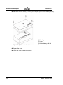
Hopper loader connection (option)
4 position
Position 1
Position 2
Position 4
Position 3
6 position
Position 1
Position 2
Position 3
Position 6
Position 5
Position 4
(250-900 models only)
Fig. 7: Connecting hopper loaders
36
Edition: February 2008
TrueBlend™
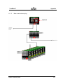
Structure and Function
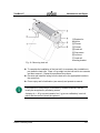
5.0 Structure and function
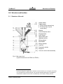
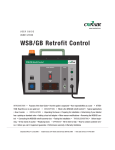
5.1
Structure of the unit
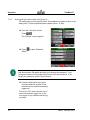
[1]
[2]
[3]
[4]
[5]
[6]
[7]
[8]
[9]
[10]
[11]
[12]
[13]
[14]
Hopper loader
Supply hopper
a. TB 45 (4 quick access bins)
b. TB 100 (2 fixed, 2 quick
access bins)
Material
Vertical dispense valve
Weighed batch
Level Sensor
Manual side gate 3
(Machine mount)
Mixing agitator
Mixed batch
Mixing chamber
Load cell
Pneumatic cylinder
Weigh bin
Cover for vertical valve assembly
Fig. 8: Side view of unit
(Typical illustration for the TB45 and TB100.)
3
Pneumatic slide gate is supplied when a blender is remote mounted, (ie. on surge bin, floor stand,
etc.) and replaces the manual slide gate. The pneumatic discharge slide gate is not installed if a
manual slide is installed and the unit is mounted directly on the injection molding machine.
Edition: February 2008
37
Structure and Function
5.2
TrueBlend™
Brief description of the functional units
(Item numbers refer to diagram on previous page)
The TrueBlend meters and mixes free-flowing plastic granulate (regrind and
natural material) and additives. The unit mixes four to six materials, depending on
model and configuration.
For example, the unit has four material hoppers [2] with mounting flanges for one
hopper loader 4 [1] each. All components are dispensed by pneumatic vertical
cone valves [4] and are fed to the weigh bin [13], which is mounted on a load
cell [11]. The pneumatic cylinder [12] opens the weigh bin.
The mixture (batch) [5] falls into the mixing chamber [10] and is mixed by an electrically powered mixer [8]. The mixing chamber holds three batches. After mixing
the batch [9] the mixing chamber is emptied by the pneumatic discharge slide
gate (remote mount) [7]. Approximately one batch remains in the mixing chamber
to ensure that the next batch can be optimally mixed.
The operation of the TrueBlend is by a PLC controller. The controller receives a
signal to feed material from the capacitive level sensor [6] in the mixing chamber
(see also 9.5.1 Adjust or replace level sensor).
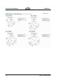
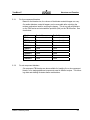
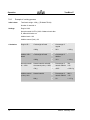
5.3
Layout of the material hoppers
4 position
Position 1
Position 2
Position 1 and 2, Main components
Position 3 and 4, Additive
components
Controller location
Position 4
Position 3
Front door – (mix chamber)
Fig. 9: Layout of the material hoppers
4
38
The material hoppers can be loaded with hopper loaders or by hand.
Edition: February 2008
TrueBlend™
5.3.1
Structure and Function
For four component blenders
Based on the blender size, the volume of the blender material hopper can vary.
On smaller blenders, material hoppers can be removable after unlocking the
retainer mechanism used for securing the hopper. This is true with all positions
on the TB45 series and color/additive positions (3&4) on the TB100 series. See
chart below:
5.3.2
Model
Pos 1 & 2
Pos 3 & 4
TB45
Removablewith tool
Removable with tool
TB100
Fixed
Removable with tool
TB250R-4
Fixed
Removable with tool
TB250-4
Fixed
Fixed
TB500-4
Fixed
Fixed
TB900-4
Fixed
Fixed
TB1800-4
Fixed
Fixed
TB2500-4
Fixed
Fixed
TB3500-4
Fixed
Fixed
For six component blenders
Six component TB blenders are also available for handling five or six component
blends, or for staging additional components used in different recipes. The following chart and drawing illustrates these combinations.
Edition: February 2008
39
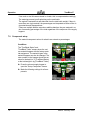
Structure and Function
TrueBlend™
Pos 1 & 2, Main components
Pos 3 & 6, Main or additive
components
Pos 4 & 5, Additive components
6 position
Position 1
Position 2
Position 3
Position 6
Controller location
Position 5
Position 4
Front door – (mix chamber)
Fig.10; Layout of six component material
hoppers
All the following six component blenders utilize fixed hopper positions:
5.4
Model
Pos 1 & 2
Pos 3 & 4
Pos 5 & 6
TB250-6
Fixed
Fixed
Fixed
TB500-6
Fixed
Fixed
Fixed
TB900-6
Fixed
Fixed
Fixed
TB1800-5/6
Fixed
Fixed
Fixed
TB2500-5/6
Fixed
Fixed
Fixed
TB3500-5/6
Fixed
Fixed
Fixed
Operating modes
The TrueBlend operates in three different operating modes:
• Gravimetric mode: all components are metered and weighed in sequence.
• Volumetric mode: all components are metered in sequence without weighing.
• Combined mode: a gravimetric cycle is followed by an adjustable number
of volumetric cycles.
40
Edition: February 2008
TrueBlend™
5.4.1
Structure and Function
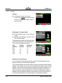
Gravimetric mode – General
The metering sequence is identical as outlined below with every metering cycle
unless Precision Additive™ (PREC) is selected:
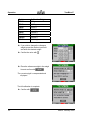
1 The regrind is metered by the vertical cone valve as a percentage of the
whole batch and fed into the weigh bin.
2 The required quantity of natural material is calculated by the controller and
dispensed as the next component.
3 The additive natural (Add N) is metered as percentage of the natural material(s).
4 The additive batch (Add B) is metered as a percentage of the total batch.
The remainder of the cycle is the same with all operating modes and is described
in 5.2 Brief description of the functional units.
5
5.4.2
Precision Additive™ applies to a low percentage (<2%) color or additive
natural material which is a critical component of the process. The Precision Additive can only be applied to one additive natural position. When
selected that material is dispensed before the natural material, but after
regrind if being used. The Precision Additive™ is dispensed and weighed.
Then the natural material is dispensed and adjusted for any minor variation
with the Precision Additive™ to assure the proper ratio; thereby, assuring
this critical component is held to the actual target setting. Then the balance (if selected) of additive naturals are dispensed to their setpoint percentages of the weighted naturals, followed by any additive batch components.
Gravimetric mode – Naturals Blend – All Naturals = 100% (extrusion)
Using this setting:
1
2
IMPORTANT
All material type selections are automatically assigned to natural.
All ingredients must add up to 100%.
Assigned recipe percentages must add up to 100. If the percentages do not add
up to 100, the recipe change will not be accepted until the percentages have
been changed to equal 100.
3
The ingredient with the smallest amount assigned to it will be added to the
mix first. On the control face the “N” for natural for this smallest ingredient
will be replaced with “1st.”
Edition: February 2008
41
Structure and Function
TrueBlend™
Your most critical component should be in the bins with the smaller valves.
IMPORTANT
4
Changing the target percentages while the blender is running will result in
the text changing from “current” to "invalid,” however the current batch will
finish. When the percentages add up to 100% the text will again display
“current”, the batch number will reset and the blender will continue with the
new recipe.
100%
current and
valid recipe
101%
invalid
recipe
Note: The
Stop hand is
displayed
when the
recipe does
not add up to
100%.
42
Edition: February 2008
TrueBlend™
5.4.3
Structure and Function
Volumetric mode
Volumetric mode is an emergency mode and must only be used if the weighing
system fails or in special circumstances.
The metering sequence is identical with every metering cycle.
1 First the regrind, then the virgin material is metered through the respective
vertical valves by time control and filled into the weigh bin. The load cell
does not operate in volumetric mode.
2 The additives/batch and additive color are added last through the smaller
vertical valves by time control.
The remainder of the cycle is the same with all operating modes and is described
in 5.2 Brief description of the functional units.
5.4.4
Combined mode
In combined mode one gravimetric cycle is followed by up to eight volumetric
cycles (number is adjustable). The total material throughput can be increased by
eliminating the weighing times. The metering cycle is described in
5.4.1 Gravimetric mode.
6.0 Start-up
Please remove the protective film on the touchscreen control for optimum
performance
IMPORTANT
Familiarize yourself with the basic functions of the controller before start-up (see
chapter 7.7).
7.0 Operation
The TrueBlend series blender is controlled at the touchscreen on the operator station controller. It can be swung forward for ease of use (see also 4.4 Positioning
controller).
The operation of the TrueBlend with four components and with conveying is described below. If the loader symbol is disabled in the start screen of your controller (see 7.3.1), you can ignore the section 7.19 Hopper loaders.
7.1
Switching on
The following prerequisites apply for operation of the unit:
• The unit is correctly wired (see 4.5.2).
• The compressed air is connected (see 4.5.1).
• All material hoppers are filled with the correct material.
Edition: February 2008
43
Operation
7.1.1
TrueBlend™
Switch on main switch
Î Switch the main switch to "l" (ON).
The start screen appears. You are at operating level "0".
• Press the icon for the gravimetric batch
blending unit (TrueBlend symbol) to
open the "TrueBlend Status" screen.
• IF your unit has the blender/loader control option,
• Press the icon for the hopper loader to
open the "Loader Status" screen.
If you did not purchase the blender/loader control package, you will not see
the loader icon
NOTE
The screen with the logout button is only
displayed if the operating level is not "0".
• Press
to
switch to other operating levels (see 7.6
Logging in/logging out).
When logging out of operating levels "1",
"2" and "3" you automatically switch to level
"0" and the logout button disappears.
If there is no input, the "TrueBlend Status"
screen is automatically displayed after 60
seconds.
44
Edition: February 2008
TrueBlend™
7.2
Operation
Menu structure
For an overview of the menu structure with the various operating levels
(Levels 1-3) see the appendix (see 11.1).
7.3
Navigation
The navigation bar is at the bottom of the screen.
It contains the following buttons:
7.3.1
Explanation of the navigation buttons
OVERVIEW (UNIT HOME)
Press this button to open the program
start screen.
The button is visible but disabled on the
"Overview" start screen.
System settings menu
SETTINGS
From the overview screen, press this button to open a screen that enables access
to various settings.
The associated settings are called from
the "Overview" screen. The button is visible but disabled on the "Settings" screen.
Blending settings menu
SETTINGS
This screen is accessible from the
TrueBlend status screen.
Edition: February 2008
45
Operation
TrueBlend™
Loader settings screen
SETTINGS
This screen is accessible from the
“Loader Status” and all other loader
screens.
Alarm overview screen
ALARM
In the event of an alarm message press
this button to gain direct access to the
alarm overview.
The button is visible but disabled on the
"Alarm Overview" screen.
This screen is accessible from all
screens.
Dry contact available for operating remote light or horn
NOTE
Back button
BACK
Press this back button on any screen to
return to the previous screen.
46
Edition: February 2008
TrueBlend™
Operation
Help button
HELP
Press this button to find help on specific
functions (online help is not yet implemented). This is an example of a help
screen.
Disabled button
DISABLED
Navigation bar functions that are not
available are disabled (grayed out).
Edition: February 2008
47
Operation
7.3.2
TrueBlend™
Explanation of keypad screens
Input with keypad
When operating the controller you are prompted to
input numbers or words.
When the relevant input field is pressed a numeric
or alphabetical keypad (separate capital and lower
case) opens, which you can use to make your inputs.
•
Confirm your input with
.
In the alphabetical lowercase keypad you can
press
to open the numeric keypad.
to
In the numeric keypad you can press
open the alphabetical upper-case keypad and then
press
to open the lower-case keypad.
Use the
slashes.
field to input spaces, colons and
If you cannot switch from the alphabetic to the numeric keypad or vice versa, the fields are disabled
(grayed out).
Input with dropdown menu
When operating the controller you are prompted to
select one of the multiple values of a dropdown
menu.
•
Press the arrow.
The dropdown menu opens.
•
Select the relevant entry and highlight it by
pressing it.
The value is imported into the input field.
48
Edition: February 2008
TrueBlend™
Operation
Scroll
Press the right/left arrows to scroll forward and
back (e.g. with settings for components or recipes).
7.3.3
Explanation of additional screen icons
Alarm display
In the event of an alarm a warning triangle is displayed at the top right corner. The alarm mode can
be set to specify when an alarm is displayed and
how the unit behaves (see 7.9.3 Input Alarm
mode).
Operating level
The operating level is shown at top left. There are
four operating levels. The operating levels are 0, 1,
2, and 3 (See 7.6.1 User levels and password input).
Time and station name display
The top bar of the screen shows the current time
and the station names. (Blender ID)
The time and station name can be set in the "System Setup" screen (see 7.15 System setup).
Edition: February 2008
49
Operation
TrueBlend™
7.4 Starting and stopping the blending process
7.4.1
Starting blender process (with set values or factory setting)
Î Press the blender icon.
The “TrueBlend Status” screen opens.
button to start the blending
Î Press the
process automatically with the last set values
or the factory settings.
The button signals
7.4.2
. (green bar)
Stopping the blending process
button to stop the metering
Î Press the
and mixing process.
The button changes to
(yellow bar). The
current batch will run until it is finished. When finished the display changes to
NOTE
(gray bar).
The bar will remain yellow until the batch of material has been dumped. The
batch will not dump until there is sufficient room in the weigh bin and the level
sensor is exposed. A green square on the screen indicates that the mixing
chamber is full and that the weigh bin has no place to put the current batch until
the material level in the mix chamber is lowered.
This green
square
indicates that
the mixing
chamber is
full, and the
level sensor
is satisfied.
50
Edition: February 2008
TrueBlend™
7.4.3
Operation
Restarting after EMERGENCY STOP
Î Switch the main power switch on.
Switching on within two minutes: the unit continues the interrupted process. This
function is used to keep downtime in the event of a short power interruption as short
as possible. The screen that was last open before switching off or power failure is
opened.
Switching on after more than two minutes: the internal functions are completely
reset after switching on. The start screen appears.
If the metering cycle is interrupted, the material in the weigh bin must be removed manually before restarting.
NOTE
7.5
This will prevent an incorrect mix ratio.
Î Remove the weigh bin carefully to prevent damage to the load cell and
empty it (see also 7.12).
Turning off the power
7.5.1
Stopping the blender at the end of a cycle
Î From the “Blender Status” screen.
button.
Î Press the
The cycle is stopped. The button switches to
batch is finished to
(yellow bar), after the
(gray bar).
If an alarm message is received when switching off and the unit does not
switch off, see chapter 8 Alarms messages and trouble-shooting.
NOTE
Edition: February 2008
51
Operation
7.5.2
TrueBlend™
Switching off in emergency
Î Switch the main switch off.
The power supply is interrupted. If the
cone valve was open, it is closed. All
other machine movement is stopped immediately. The batch is not finished.
The main switch can also be locked
manually with a lock.
52
Edition: February 2008
TrueBlend™
7.6
Operation
Logging in/logging out
7.6.1
User levels and password input (for service users only!) (Level 3)
The system covers several user levels:
• Level
: enables access to all guest functions
(no password protection)
• Level
: enables access to all operator functions
(password: 3333)
• Level
: enables access to all setup functions
(password: 2222)
• Level
: enables access to all service functions
(password: 1111)
After logging out operating level "0" is opened. Then the user level can be
changed by entering the relevant password.
NOTE
When you select functions that are not part of your current user level, e.g.
calibration of the scales at user level "0" or "1", you will be prompted for a
password to change the operating level.
This is not explicitly mentioned in the following examples.
Example of password input:
Î Enter the relevant password.
The operating level is changed.
7.6.2
Changing password (for service users only!) (Level 3)
With level 3 access you will have the ability to view all levels of passwords and
will be able to change all passwords. Level 0 and 1 can not view or change
passwords.
Edition: February 2008
53
Operation
7.6.3
TrueBlend™
Auto logout (for service users only!) (Level 3)
The system has an auto logout function. This enables the system to return to operating level "0" after a specified period (default value = 15 min).
Î From the “Overview” screen,
Press
.
The "Settings" screen appears.
Î Press
Setup".
NOTE
to open "Password
If you want to change the password press on the field beside the user level
and the calculator will appear allowing you to change the password. If you
change a password it is important that you note your new password. If you
forget your password, contact Conair Service.
Î Press the field beside auto logout
(min) and enter the number of minutes before you will be automatically
logged out.
The input of "00" means that the user is
never automatically logged out. In this
case logout is only possible with the logout button.
54
Edition: February 2008
TrueBlend™
7.6.4
Operation
Parameters/Global Reset (for service users only!) (Level 3)
The overscreen
Î Press the button beside "Parameters".
IMPORTANT
Please contact Conair service before
attempting to make a change to the
parameters, number or value. Currently,
there are no parameter functions that
can be set or changed.
The "Control Variable" screen opens.
Î Assign a parameter number and a parameter value (no function currently
set).
or
depending
Î Press
on whether the parameters should be
readout or set (no function currently
set).
Î Press
at "Global Reset" to reset
the controller completely. (Defaults to
the home screen.)
A "Global Reset" can also be done by
switching off the unit for more than two
minutes. Once “off” is pressed the unit will
default to the home screen.
Î Press the
button to toggle from
“off” to “on” at "Diagnostic Report" to
create accuracy reports for the service.
(Refer to Section 7.14 for connection
options.)
Edition: February 2008
55
Operation
7.7
TrueBlend™
Start-up
Please remove the protective film on the touchscreen control for optimum
performance
IMPORTANT
7.7.1
Checking functions in manual mode
All mechanical parts can be manually actuated with the "Manual Mode" function.
If a vertical valve or the mix discharge is opened in manual mode, they are closed
automatically by switching the main power switch to OFF or if the power fails.
DANGER OF INJURY!
WARNING!
If you reach into the mix discharge or the dosing unit when the compressed
air supply is connected, hand injury may be the result.
Î Never reach into the mix discharge or dosing unit.
Conditions for operation
The safety door must be closed.
Î In the "Overview" screen press the
TrueBlend icon.
The “TrueBlend Status” screen appears.
Î Press
.
The "Settings" screen appears.
Î Press
to start manual mode.
Now you can operate the material hoppers,
weigh bins, mixers and discharge slide
gates if supplied.
56
Edition: February 2008
TrueBlend™
Operation
If the unit is running or is being calibrated, it is locked to prevent testing of the
manual operation.
NOTE
Testing alarm beacon
button to
Î Press and hold the
check that the alarm beacon and horn
operates. These devices are located
on the door of the electrical power box.
Checking material hoppers
The icons that display the status of the hoppers are at the top of the screen.
Î Press the
buttons in sequence to
check that the various material hoppers
valves can be opened and closed.
(Shown are four hoppers, if your unit
has six, all six will be displayed only on
the 250, 500, 900, 1800, 2500 and
3500 models.)
Edition: February 2008
57
Operation
TrueBlend™
Checking weigh bins, mixers and discharge slide gates
Press the buttons beside the unit icon to
test the function of the weigh and mix
chamber components.
Î Press the first button to open and close
the weigh bin.
or
Î Press the middle button to switch the
mixer on and off.
or
Î Press the bottom button to open and
close the optional discharge slide gate. 5
or
(Flow control valve)
Note: Only functions when a pneumatic
discharge slide gate is installed.
Î Make sure that all parts of the unit can
be opened and closed:
Testing the mix chamber safety interlock
switch
The safety door must be closed.
Î Press
.
The "Settings" screen appears.
Î Press
5
58
to start manual mode.
Only functions when a pneumatic discharge slide gate is installed.
Edition: February 2008
TrueBlend™
Operation
Î To the right of the mixer icon press the
middle
or
.
The mixing blades must rotate.
Î Open the safety door.
The mixing blades must stop.
Î Close the safety door.
The mixing blades should rotate again.
This screen mask will only be closed when
all actions have been completed.
When you open the door, the mask will appear, indicating an alarm condition.
NOTE
Edition: February 2008
59
Operation
7.7.2
TrueBlend™
Calibrating
NOTE
Conair recommends performing a manual calibration at start-up or material
change with a dramatic change in the bulk density of the material being
blended. This allows the blender to reach its optimal working point more
quickly.
7.7.2.1 Calibrating load cell(s):
Calibrating scales - zero calibration
The scales are calibrated at the factory. The zero calibration is made to set the
scales to "0". During shipment and/or operation minor deviations may occur, e.g.
from single pellets of material remaining in the weigh bin or positioning of the
weigh bin on the load cell support bracket. However, the controller runs an internal zero calibration tare before every cycle.
Calibrating scales - full calibration
A manual full weight calibration is only required after a fault, replacement of load
cell(s) or for scale certification. The calibration must be conducted by authorized
personnel only. The reference weights are as shown below for the various models:
Conditions
The weigh bin must be empty.
Î In the "Overview" screen press the
TrueBlend icon.
The "TrueBlend Status" screen opens.
Î Press
.
The "Settings" screen appears.
to open the "Scale CalibraÎ Press
tion" screen.
The "Scale Calibration" screen appears. It
can only be calibrated with the blender
stopped. The main power remains on.
60
Edition: February 2008
TrueBlend™
Operation
Zero calibration
Î Press
.
"0" is displayed for "Actual Weight".
Full calibration
(for service users only!) (Level 3)
to open the "Full CaliÎ Press
bration" screen.
Before the "Full Calibration" screen appears, you will be reminded that a full calibration cannot be interrupted:
Î Press "Continue" if you want to proceed with the full calibration.
or
Î Press "Abort" to stop the full calibration.
Î Make sure that the weigh bin is empty
of material.
Î Press “Enter” to confirm.
A reference weight of 1250 g is assumed
as the factory setting for a TrueBlend 100
series blender or 750 g for a TrueBlend
045 series model.
Edition: February 2008
61
Operation
TrueBlend™
Model
Calibration Weight
TB045
750 g
TB100
1,250 g
TB250
3,000 g
TB500
6,000 g
TB900
10,000 g
TB1800
22,000 g
TB2500
30,000 g
TB3500
50,000 g
Î If you wish to change the reference
weight, press the number input field
and enter the desired weight.
.
Î Confirm the value with
Î Place the reference weight in the weigh
.
bin and confirm with
The current weight is compensated and
displayed.
The full calibration is complete.
Î Confirm with
62
.
Edition: February 2008
TrueBlend™
7.7.2.2
NOTE
Operation
Calibrating material throughput
The material throughput calibration is automatically run on startup and is selfoptimizing during production.
The respective dispensing valve(s) are run with reduced batch weight(s) at
startup. The optimum working point is set after several batches. A high mixing precision is quickly reached with a small quantity of material. Finally it
is switched to the preset batch weight.
Conair recommends performing a manual calibration at start-up or material
change with a dramatic change in the bulk density of the material being
blended. This allows the blender to reach its optimal working point more
quickly.
Conditions
The weigh bin must be empty.
Î Press on a material hopper on the
"BLENDER Status" screen.
or
Î Press on a material hopper on the
"TrueBlend Totals" screen.
The "Setup Component" screen appears.
to open the "Material
Î Press
calibration" screen.
The "Material calibration" screen appears.
Edition: February 2008
63
Operation
TrueBlend™
"1" indicates the material hopper number.
You can scroll forward and back with the
arrows.
Î Press
for material hopper "1".
Î Press
bin.
again to empty the weigh
Î Run the process for all components that
require calibration.
Important:
The screen cannot be closed until the procedure is complete.
For input of the material percentages, see
section 7.9.1 Input of material percentages.
64
Edition: February 2008
TrueBlend™
7.7.3
Operation
Input TrueBlend Model/Name (for service users only!) (Level 3)
Î In the "Overview" screen press the
TrueBlend icon.
The "TrueBlend Status" screen opens.
Î Press
.
The "Settings" screen appears.
Î Press
to open the
"TrueBlend Model/Name" screen.
The "TrueBlend Model/Name" screen
appears.
Î Select the appropriate TrueBlend
model in the dropdown menu (Model
45/100/250/500/900/1800/2500/3500).
Edition: February 2008
65
Operation
7.7.4
TrueBlend™
Input TrueBlend name
Î In the "Overview" screen press the
TrueBlend icon.
The "TrueBlend Status" screen opens.
Î Press
.
The "Settings" screen appears.
Î Press
to open the "TrueBlend
Model/Name" screen.
The "TrueBlend Model/Name" screen appears.
Î Assign a name to the unit with alphanumeric keypad to give it a unique
identification.
Î Confirm with
.
Explanations of the “minimum retry
limit (%)” and “the maximum limit
batchweight (%).
Once a position has fed the setting (95%
or greater) the control will move on to the
next setting. If the blender does not reach
the setting within a prescribed number of
retries, it then evaluates whether it has
reached 50% of the target. If the blender
has not reached 50 % of the target the
blender will alarm on “Low Material,” and
continue to retry indefinitely until it
reaches the target weight.
The minimum retry limit (95) can be set
from 95 to 100.
NOTE
66
Increasing the minimum retry limit will decrease the average blender
throughput rate. A larger number of retries add up to more time to make a
batch. However, somewhat better accuracy can be achieved with the higher
number.
Edition: February 2008
TrueBlend™
Operation
The batch size limit multiplier controls the maximum batch dispensed, regardless
of the condition of the (too much material) alarm button. All blender weigh bins
have some excess volume capacity to accommodate variations in material bulk
density. This setting uses that excess capacity to improve accuracy.
NOTE
If running high percentages of light density material (regrind) you should reduce the maximum batch weight setting for this particular model. (See section 7.10.2 Setting Weight Bin Batch Weight.)
Precision Mode – If running precision or natural blend and the first ingredient is
overfed by a large amount the rest of the batch will be diluted as much as possible based upon the maximum batch limit.
7.7.5
Activating Batch Setting
Î From the Blender Status screen,
press the Settings navigation button.
The blender Settings screen will appear
as shown at right. The bottom panel on
this screen allows one to access the
Batch Mode screen where the Batch
Mode of operation can be Turned On and
setup for the amount of blended material
in that batch.
Setting the blender in the Batch Mode
In normal operation the blender will
continue to make individual blended
batches of material until the level sensor
is satisfied or the blender is turned off by
the selection button on the Blender Status
screen. When placed in the Batch Mode
the blender will blend the current settings
or recipe until the preset Batch Weight is
accomplished and then stop.
Î To activate the Batch Mode, press the
off button in the top panel position.
The “gray” button will change to “green”
indicating this mode is now activated.
Edition: February 2008
67
Operation
TrueBlend™
Î Next enter the target weight in the
next panel position.
The units will be either “lbs” or “kg”. If you
need to change from one to the other,
please refer to section 7.15 System
Setup.
Î To start the blender operating, return
to the Blender Status screen and
press the “On/Off” button.
The blender will then begin to weigh the
target value. You can return to the Batch
Mode screen and monitor process as this
is being done.
NOTE
The actual weighed value will be at least the target value you have entered plus
up to one additional weighed batch of the blender model you are using. The
reason being that the blender can’t stop in the middle of an individual batch, but
the actual total weight will be indicated and all the ingredients will be included in
correct proportions.
The next panel position on this screen will
display the “Current Weight” which could
be a portion of the target value if one is
viewing during operation or the target
weight if the blender has finished.
The last panel on this screen displays the
status of the batch mode which can be; --(if the batch Mode is not activated),
“Running” (if in the process of making a
Batch), “Finished” (if the targeted batch
has been completed) or “Stopped”
(appears after the previous Batch amount
has been reset).
68
Edition: February 2008
TrueBlend™
Operation
NOTE
When the target value has been reached, a screen mask will appear indicating
“Target weight of the dispense has been reached”. There is an acknowledge
button “OK” to remove the message.
NOTE
Reaching the preset target weight will also stop the blender operation. To begin
another Batch after resetting, return to the Blender Status screen and press the
On/Off button.
Edition: February 2008
69
Operation
7.7.6
TrueBlend™
Advanced Operation Settings (Password level 3 only)
Advanced Operation Settings are accessed through the Operating Times (Oper.
Times) tab from the blender settings screen.
Extrusion
process
(100%)
The parameters that are accessible through these menus are available for
advanced users, unusual operating conditions, or setup of the control for blender
retrofit applications. It should not be necessary for these parameters to be
changed in the majority of cases. Please consult with Conair service before you
change any of these parameters.
A. Settling times
70
Edition: February 2008
TrueBlend™
Operation
The settling time is the time after a component dispensed into the weigh bin, while
multiple weight reading are taken. (This time allows the material to settle and the
load cells to recover from the dumping process before the final weight reading is
taken.) The time should be entered in milliseconds For example, in the above
screen shot 2000 milliseconds is entered which equals 2.0 seconds. For most
Trueblend applications the default time of 2000 milliseconds should be
acceptable. In retrofit applications where slow screw feeders are used these times
may need to be increased to allow the material to drop from the feeders.
B. Batch times
The units can be changed by touching the
symbol and will toggle to the other setting
(Kg in this case). The display will not refresh
until the next batch
Throughput and sensor times are only available in gravimetric mode..
NOTE
Sensor to Sensor time –
Batch Settling time – The Batch settling time is the time prior to beginning a
batch, where the blender waits for the weigh bin to settle and return to the tare
weight.
Weigh Bin Open time – The weigh bin open time is the time that the weigh bin is
actually open as the material is dumped into the mixing chamber.
Second Dump time – The second dump time is the length of time that the weigh
bin opens a second time to knock off any additional material that may remain in
the weigh bin. This feature is used on the TB45 and TB100 blenders.
Edition: February 2008
71
Operation
TrueBlend™
Flow Control Valve time – The flow valve time is the time that the material valve
under the mixing chamber is open to allow the material to exit the mixing
chamber. (When this option is included)
C. Dosing Rates
This screen displays the last dosing time. This value can be useful for optimizing blender valve sizing.
NOTE
The Dosing rates are the flow rates in gm/sec of each component in the mix. This
is the same value as is displayed on the individual component screens. In normal
operation the dosing rate starts with a default value and the default value is
modified by the blender software during a material calibration, or as blending
progresses, to reflect the actual material flow rate seen for each component.
72
Edition: February 2008
TrueBlend™
Operation
7.7.7
Natural Blend button – The Natural Blend button, when selected, ensures
that the blender will only run if all components add up to 100%. A warning
hand will be displayed above the ON/OFF button to prevent starting. If the
percentages are changed while the blender is running, a warning message will be
displayed and the blender will stop the current process.
NOTE
When running in Natural Blend – All Naturals (extrusion); any recipe changes
that add up to 100% will automatically be used for the next batch and the
display will be changed from invalid to current. The ingredient assigned the
smallest amount in the recipe will be labeled “1st” and fed first. All other ingredients will be adjusted based upon the actual weight of the “1st” material.
Edition: February 2008
73
Operation
7.8
7.8.1
TrueBlend™
Blending process
Assigning components – factory default setting
The components are assigned at the factory as follows:
Component 1: regrind
Component 2: natural material
Component 3: additive/natural (color)
Component 4: additive/natural (color)
Component 5: additive/natural (color)
Component 6: additive/natural (color)
The assignment of the components can also be changed
(see 7.9 Component setup).
4 position
Position 1
Position 2
Controller location
Position 4
Position 3
Front door – mix chamber
Fig. 11: Layout of the material hoppersfour position models
(All models)
74
Edition: February 2008
TrueBlend™
Operation
6 position
Position 1
Position 2
Position 3
Position 6
Controller location
Position 5
Position 4
Front door – mix chamber
Fig.12: Layout of the material hoppers –
six position models (only available on TB250,
TB500, TB900, TB1800, TB2500, and TB3500)
Position 1
Position 2
Position 1
Position 2
Position 6
Position 3
Position 5
Position 4
a. Five Position
Position 3
Position 5
Position 4
b. Six Position
Fig.13: Layout of five and six position models –
(only available on TB1800, TB2500, and TB3500)
Edition: February 2008
75
Operation
7.8.2
TrueBlend™
Example of a mixing process
Initial values:
Total batch weight: 1000 g (TB Model TB100)
Number of materials: 4
Settings:
Regrind: 20%
Natural material: AUTO (100% of balance batch after
R, AB and AN taken out
Additive batch: 10%
Additive natural (Color): 2%
Calculation:
Regrind: R =
Additive: AB =
Batch
Natural material:
N = 100%
Additive natural
(Color): AN =
76
Total weight of batch
×
Percentage of
regrind
1000 g
×
20%
Total weight of batch
×
Percentage of
additive
1000 g
×
10%
= 100 g
Percentage of
natural material
700
1.02
Natural material and addi- ×
tive natural (color) = 102%
= 200 g
700 g
×
100%
= 686.3 g
Natural material
×
Percentage of
natural material
686.3
×.02
686 g
×
2%
= 13.7 g
Edition: February 2008
TrueBlend™
7.8.3
Operation
Typical dispense cycle based (7.8.2) settings
1st Step: regrind is metered
regrind 20% of total weight = 200 g
2nd Step: Natural material is calculated
as 100% of the balance of batch = 686 g
(automatically calculated/metered)
3rd Step: additive natural is metered
(Color) 2% of N = 13.7 g
(automatically calculated/metered)
4th Step: additive batch is metered
10% of total weight = 100 g
(automatically calculated/metered)
The controller must be set to match this sequence.
The percentage of natural material is automatically calculated by the controller.
[Sum of Natural(s) material = 100 %].
The percentages of the additive naturals are always based on the natural(s)
material.
The percentages of the additive batch are always based on the entire batch and
therefore are metered last.
Edition: February 2008
77
Operation
TrueBlend™
If too much or too little was metered in a batch, this is compensated accordingly
The metering process is self-optimizing on the next batch.
The regrind is metered first and deducted from the total batch weight. If there is
more than one virgin material, the percentages are interpreted as ratios of the virgin materials and dispensed next.
If there are multiple additive naturals or additive batches, they are metered in order of ascending percentage of the total regardless of the sequence of the supply
hoppers.
7.9
Component setup
The material component values for a batch are entered as percentages.
Conditions
The "TrueBlend Status" and
"TrueBlend Totals" screens show the various material hoppers with the factory material assignment. The material types in the
material hoppers can also be changed. The
outer number in the hoppers shows the set
value for the batch in % (TrueBlend Status)
or the total weight in kg (TrueBlend Totals).
Î Press the relevant supply hopper to
open the "Setup Component" screen.
Î Make the following settings for all components.
78
Edition: February 2008
TrueBlend™
7.9.1
Operation
Input of material percentages
Î Input the percentage for the material
component by pressing the input field
beside "Percent %".
Î Input the value with the numeric keypad. Note: If using multiple naturals,
they must equal 100%.
Î Confirm the value with
.
The metering rate in g/s is automatically
learned by the system, but by completing a
manual calibration the blender hones in on
the rate with greater precision.
7.9.2
Input of Material type
Î After "Mat. type" input the component
for the supply hopper.
Î Select the desired component --- (a
series of three dashes indicates an unused hopper and can be assigned to
any position. It is important to note that
if you are not using a hopper, material
type must be set to “---“), regrind, natural material, additive batch, additive
natural, or Precision Additive™
(The Precision Additive™ can only be
assigned to one additive natural position on the blender.)
Î Factory default settings are position 1,
Reg.; position 2, Nat.; position 3, AddN;
position 4, AddN; position 5 (if applicable), Off; position 6 (if applicable), Off.
Edition: February 2008
79
Operation
7.9.3
TrueBlend™
Input Alarm mode
Every material component can be assigned
a specific alarm mode. The alarm mode
shows the alarm response to overmetering
or undermetering. The "Warn" mode is set
for regrind and “stop” for natural and additives at the factory:
Î Press the down arrow for the selection
box and select the desired alarm mode.
• ------: No alarm message, unit continues
to run without message.
• Warn.: Alarm message is displayed, but
unit continues to run.
• Stop: Alarm message is displayed, but
the blender will continue to try to dispense the component until at least 50%
has been fed or the continue or abort
button has been pressed. If continue is
pressed the control will move on to the
next component. Abort will stop without
dumping to allow you to manually empty
the weight bin.
7.9.4
Input Dosing retries
The “Dos. retry” specifies how often material dispensing will be retried in the event of
undermetering before an alarm is displayed
(if alarm mode is set to "Warn" or "Stop",
see 7.9.3 Input Alarm mode).
The factory setting is 4.
(i.e. material will attempt four times to obtain target weight. If it fails an alarm will
occur).
Î Input the value for metering attempts
with the numeric keypad.
Î Confirm the value with
80
.
Edition: February 2008
TrueBlend™
Operation
7.10 TrueBlend Setup
Operating mode, batch weight, mixing time and interval time can be set in TrueBlend Setup.
Î Press the TrueBlend body icon (green
column) in the center of the "TrueBlend
Status" screen.
Î The TrueBlend setup will come up.
7.10.1
Setting Operating mode
The operating mode specifies whether the unit will operate gravimetrically, volumetrically or in mixed operating mode (see 5.3.1 Operating modes).
Î Press the dropdown menu and select
the operating mode.
• grav.: all components are metered and
weighed in sequence (gravimetrically).
• volu.: all components are metered in
sequence without weighing (volumetrically).
• mix. 1-8: a gravimetric cycle is followed
by a number (1-8) of volumetric cycles.
The number shows how many volumetric cycles will follow a gravimetric cycle.
Edition: February 2008
81
Operation
7.10.2
TrueBlend™
Setting Weigh Bin Batch Weight
Materials with a lower bulk densities (ca. <35 lb/cu ft) may not fit in the weigh bin
and granulate may overflow. The batch weight must be reduced in this case. The
factory setting is 900 g for the TB100 model or 400 g for the TB045 model, (see
chart below).
Model
Batch Weight
Min Weight
Maximum Weight
TB045
400 g
280 g
480 g
TB100
900 g
630 g
1100 g
TB250
2500 g
1750 g
3000 g
TB500
4000 g
2800 g
5000 g
TB900
8100 g
5700 g
9800 g
TB1800
18000 g
12600 g
21600 g
TB2500
25000 g
17500 g
30000 g
TB3500
35000 g
24500 g
42000 g
Î Press the input field beside "Batch
Weight and input the desired batch
weight with the keypad.
Î Confirm the value with
.
If the minimum value is not reached, the
minimum value from the chart is automatically input. If the maximum value is exceeded, the maximum allowable value is
automatically input.
The batch weight can also be increased for
heavy bulk materials. This will make the
material throughput in lbs/hr somewhat
higher.
Î Make sure that the weigh bin does not
overflow.
82
Edition: February 2008
TrueBlend™
7.10.3
Operation
Setting Mixing time
The mixing time shows how long a batch is mixed after discharge from the mixer.
The factory setting is 10 to 15 seconds, depending on model.
Î Press the input field beside "Mix. time"
and input the desired duration in seconds with the keypad.
Î Confirm the value with
7.10.4
.
Setting the Interval time
The interval time shows the time for which the mixer will “jog” several rotations to
ensure that the mixing blades do not stop in front of the sensor and thus generate
a "FULL" message. The factory setting is 30 seconds.
Î Press the input field beside "Interval
(s)" and input the desired duration in
seconds with the keypad.
Î Confirm the value with
7.10.5
.
Setting Damping
The following settings are available for impact and vibration damping:
Î Select values < 2 to increase the sensitivity of the scales.
Î Select values > 2 to reduce the sensitivity of the scales and to reduce alarm
messages.
The factory setting for damping is "2".
Edition: February 2008
83
Operation
TrueBlend™
7.11 Working with recipes
Recipes are used so constant and recurring production processes can simply be
called up instead of being input again and again. The controller can store up to 50
recipes.
The recipe must be called before recipe data can be changed, i.e. it must be
active.
NOTE
7.11.1
Calling recipe status
Î Press "Recipe" in the "TrueBlend
Status" screen to view the recipe
status.
Î The recipe screen will appear
7.11.2
Assigning an order number
Î Using the alphanumeric keypad assign
an order number or job number.
84
Edition: February 2008
TrueBlend™
7.11.3
Operation
Save a new recipe
Î Press
to assign a recipe name
and to save the recipe.
7.11.4
Naming a recipe
Î Use the scroll arrows to select a storage location for the recipe or input a
storage location number directly.
Î Assign a recipe name with the keypad.
A recipe name has a maximum of eight
characters (alpha-numeric).
Î Confirm the value with
Î Press
Edition: February 2008
.
to save the recipe.
85
Operation
TrueBlend™
The formula for all components is displayed
below in the component view.
When it is saved the current data are transferred to the preselected recipe name.
Existing recipes can also be overwritten
with this method.
Saving is only possible if a recipe name has been assigned. Otherwise a
warning is displayed and the recipe is not saved.
NOTE
Error message
Î Press on the input field and assign a
recipe name.
to save the recipe.
Î Press
7.11.5
Deleting a recipe
Î Press
86
.
Edition: February 2008
TrueBlend™
Operation
Î Select the recipe that you want to delete with the scroll arrows or by direct
input.
Î Press
.
The recipe is deleted from the memory.
7.11.6
Load/view a recipe
Î Press
.
Î Select the recipe that you want to load
with the scroll arrows or by direct input.
Î Press
.
The recipe is loaded and the formula for all
components can be viewed.
Edition: February 2008
87
Operation
TrueBlend™
7.12 Changing material in a blender component
(also valid for all other components)
7.12.1
Detachable Material Hopper Procedure
Detachable material hopper for TB45 (4 bins) and TB100 (2 bins) models,
and TB250R (2 bins).
NOTE
All detachable material hoppers on the above referenced models are held in place
with a captive retainer (screw) held in the hopper support frame. The retainer
stabilizes the detachable hopper when mounted in the blender support frame from
forces exerted on the hopper by resin weight and various types of automatic
loading/receiving device(s) during normal vibration from the process. There is a
separate retainer for each detachable hopper.
When removing any of these detachable hoppers for cleaning or material
changeover; first, remove the automatic loading/receiving device; then use the
proper hex head socket or screwdriver and back out the captive retainer. Hopper
can then be removed.
Upon re-insertion of the detachable hopper, it is very important to re-anchor
the respective hopper(s) using the captive retainer to provide stability
during normal operation of the blender. Once the hoppers have been placed
and anchored, the respective loading / receiving devices can be mounted.
Captive retainer
88
Edition: February 2008
TrueBlend™
7.12.2
Operation
Manual cleaning:
Î Turn the power off with the main disconnect switch on the power cabinet
Î Disconnect compressed air
Î Open front access door and remove
the weigh bin
Î Position some type of deflector (cardboard tray) to divert material from collecting in the mix chamber to an outside drum or bucket. Also available is
the Conair Drain Chute Accessory.
This allows the discharge valves to be
operated in the manual mode.
Shown
with the
optional
drain
chute and
safety
interlock
Î Using a “dowel rod” approximately
12 inches long, press vertically into the
respective valve opening and raise the
plunger cone to allow material to flow
from the material compartments.
Î Material will flow out of the hopper
compartment through the valve opening onto the deflector and into the drum
or bucket.
Î Discharge the material completely and
clean the material hopper from the top
down.
Î You may also want to clean the material receiver at this time while accessing
the gravity dump valve through the respective blender clean out door.
Edition: February 2008
The optional drain
chute is available
from Conair.
Contact Conair Parts
1 800 458 1960
From outside of the
United States, call:
814 437 6861
89
Operation
TrueBlend™
Î Open the “quick-release” locks of the
mixing chamber end cover and remove
it.
DANGER OF INJURY!
WARNING!
After extended operation the edges of the mixing blades can be knife-sharp
and may cause injuries by cutting.
Î Wear gloves when touching or cleaning the stationary mixer.
Cleaning the mixer
Î Once the material compartment has
been cleaned, remove the deflector
Î You will now proceed to clean the mixing
chamber and shut off valve at the bottom
of the chamber.
Î To fully evacuate the mixing chamber
you may need to run the mixing agitator
for a short time.
Î Close the mix chamber access door.
Restore power by closing the main disconnect switch.
Î Now you can manually run the mixer for
a short time (see 7.7.1 checking functions in manual mode) to lower the material level
Î If applicable, open the discharge slide
gate at the bottom of the mix chamber.
Î Open the mix chamber access door. The
safety unlock switch will prevent operation of the mixer with the door open.
90
Edition: February 2008
TrueBlend™
7.12.3
Operation
Clean-out with optional drain chute with safety interlock
Î Open front access door to the mix
chamber.
Î Remove the weigh bin.
Î Position the optional drain chute to redirect material from collecting in the mix
chamber to an outside drum or bucket.
Be sure to engage safety switch of drain chute into compartment receptacle.
NOTE
Edition: February 2008
91
Operation
TrueBlend™
Î In the "Overview" screen press the
TrueBlend icon.
The "TrueBlend Status" screen opens.
Î Open the "Settings" screen with
Î Press
.
to switch to “manual mode”.
Î Press on the appropriate material hopper icon to open the respective vertical
valve.
Removing material
The dispense valve unit is opened and the
material runs out of the material hopper
through the optional deflector to the collection receptacle.
Î Discharge the material completely and
clean the material hopper from the top
(use the compressed air nozzle supplied if necessary).
Î Press on the appropriate material hopper icon again to close the dosing unit.
Î Remove the optional drain chute.
Now you may follow the steps outlined above (cleaning the mixer) to access and
clean the mix chamber and bottom discharge valve.
92
Edition: February 2008
TrueBlend™
Operation
7.13 Checking total throughput
You can display the total throughput of all
components from the status screen.
Î Press the “Totals” icon
the total weight view.
to open
The total weight and the batches run are
displayed in the center above the
TrueBlend body icon (orange column).
Î Press
to advance to advance to
the screen reset totals.
Reset
All displayed throughputs are listed in the
Global Reset.
The actual throughput values are in the
bottom line.
Î Press
to add the actual
total weight, the actual time and data
and the number of batches to the list.
The active register (total weight and
batches) are set to "0".
Edition: February 2008
93
Operation
TrueBlend™
7.14 Creating reports
7.14.1
Reports for batches, shifts, recipes and scales
Î In the "Overview" screen press the
TrueBlend icon.
The "TrueBlend Status" screen opens.
Î In the "Overview" screen press
the "Settings" screen.
Î Press
to open the “Report”
selections.
•
Shift report: Records individual ingredient and total material usage
during defined interval.
Î Input start time and interval time.
The report position is started daily at the
specified start time and after expiry of the
interval time.
• Batch report: the batch report shows the
averaged batch parameters of the last
three batches at the end of the cycle.
Batch report is always on.
NOTE
• Recipe report: the recipe report shows
all available recipes with the type of material and the percentages of the various
materials.
• Scale report: the scale report shows the
current measured weight with the current date and time.
94
Edition: February 2008
TrueBlend™
7.14.2
Operation
Report generator – TrueBlend Reports
The messages from the TrueBlend
controller are sent through the message capture and report program
“TB_Reports” to a computer.
Data can be outputted either through
the V 24 serial interface (RS232) or
the network port (cable connection to
the appropriate computer is required).
The serial interface V24 (RS232 can
be enabled from the “Overview/Settings” menu
The TB_Report
Software Package
is available from
Conair.
Contact Conair
Sales.
1 800 654 6661
From outside of
the United States,
call:
412 312 6000
ON = serial (V24/RS232)
OFF = network (UDP)
The transmitted message types are:
• Material data
• Batch data
• Alarm messages
• Scale data
• Recipes
Reports can be created from the data filtered by data, time and unit or IP address.
The reports can be displayed on screen and printed.
It is also possible to save the message files in csv format and read and edit them
in spreadsheet programs such as Microsoft Excel. The TB_Report software package is available from Conair.
After starting the program
After starting the program the incoming messages are immediately received and
saved as a *.rpt file if the interface is connected and configured correctly.
There is no way to switch on or off the message capture in the TB_Report.
Material data, batch data, scale data and recipes are captured via
"TrueBlend Status/Settings/Reports". (optional software package)
Alarm messages are captured via "Overview/Settings".
Edition: February 2008
95
Operation
TrueBlend™
Main program window
7.14.3
Operation
Converting data
Î Select "File/Export data" to open the
selection dialog and select the message files that you want to convert.
Î Select "Open" to start the export and
save the file in csv format.
Maintaining files
Î Select "File/File service" to open the
maintenance window.
Î Highlight the position you want to edit
and carry out the corresponding action with the icons.
The position of the cursor (row = Z; column = S) is shown in the bottom left of
the field below beside the file name of
the open file.
Back up files
Î Select "File/Backup files" and select
the directory to which all message
files (*.rpt) will be copied.
96
Edition: February 2008
TrueBlend™
Operation
Creating reports
The "Reports" menu item enables the
data of the various message types to be
collected.
Î Select the desired message type in
the menu.
Î Input the time range and the Unit No.
in the filter dialog.
Î Click "OK" to create the report and
display it on the screen.
or
Î Click "Cancel" to stop the report
creation.
Making settings
The program settings for the directories
used, the serial port (ComPort), language and printer can be selected in the
settings menu.
Directories
Î Select the directory where the message files will be saved in the dialog.
ComPort
Î Select the desired ComPort settings
in the dialog.
The directories and ComPort settings are
stored in the configuration file and are
available next time the program is
started.
Language
Î Set the operating language.
Edition: February 2008
97
Operation
TrueBlend™
Printer
Î Select the printer.
Changes of language and printer remain
in effect until the program is closed or
until the next change. They do not
change system settings.
Conair UDP
Refers to network settings that do not
currently exist.
Printing online
Settings for direct output of messages
on screen and/or printer can be made
with this function.
Î Select "Settings/Print online".
Î Select the checkbox for the desired
actions and accept them with "Apply"
or "Save".
"Save" saves the specified values to the
configuration file. The output to screen is
the default setting.
If only one message is read, it is displayed in a new window on receipt.
The window is moved to the foreground
with every message, because only the
last 15 messages are displayed.
Î Press the buttons on the top edge of
the screen for other selected message types.
If the print checkbox is active, a print job
is generated at the same time, to which
the messages are written. They are only
printed out if one page is filled or the job
is terminated by closing the window.
The print button at the bottom of the
screen operates independently to this
and generates a printout of the currently
available messages (maximum 15) in all
active message windows.
98
Edition: February 2008
TrueBlend™
Operation
If both print modes are used simultaneously print errors may occur in some
circumstances.
NOTE
The status of the online checkboxes
is shown in the status line:
A displayed letter represents the
"Enabled" function.
M =
Material data
B
=
Batch data
W =
Scale data
R =
Recipes
A
Alarms
=
<P> = Print online on printer (in red)
Version
Î Select the "Info" menu.
The current version and the build
data are displayed.
For more detailed descriptions of configuration and the format of message
files see the appendix.
NOTE
Edition: February 2008
99
Operation
TrueBlend™
7.15 System setup
Different settings can be made in the system, such as station name, operating
language, date and time settings and units.
Setting station name
Î Input a station name with the alphanumeric keypad.
Setting operating language
The operating language can be changed
for the entire controller. English (factory
setting), Spanish, French and German are
available.
Î Select the desired language in the selection menu.
After switching the language you are
prompted to restart the system.
Setting date and time
Î Input the date and the time.
Make sure that there are no dots between the numbers.
You have a choice of:
Date format: [mmddyyyy] (USA)
Date format: [ddmmyyyy] (European)
Time format: [hhmmss].
Setting unit of weight
Î Select "lbs" or "kg" as the unit of weight
by pressing
. The
button toggles to "lbs" and back.
The button toggles to "kg" and back.
The unit of weight only refers to the total
throughput and the total weights.
100
Edition: February 2008
TrueBlend™
Operation
7.16 Panel setup
Screen settings can be made here.
Contrast
Î Set the contrast (brightness) of the touch
panel (10-100; default 100).
Shutoff
Î Set the time after which the touch panel
will change to sleep mode (10600 seconds; default 180).
Contrast shutoff
Î Set the contrast (brightness) for sleep
mode (10-20; default 10).
The following settings are only required if
your unit is to be part of a network:
IP address (for service users only!)
(Level 3)
Î Input the IP address of the controller (default 192.168.3.249).
A reset is run after changing the IP address.
After the reset the controller must be
switched off and on again.
Edition: February 2008
101
Operation
TrueBlend™
Module number (for service users only!)
(Level 3)
Î Input the module number of the controller (default 249).
It must always match the last octet of the IP
address. After changing the IP address the
module is always automatically changed to
match the IP address. If it is changed later,
the controller must also be switched off and
on again.
Subnet mask (for service users only!)
(Level 3)
Displays the current subnet mask of the controller (all models).
7.17 System info
The software status of the TrueBlend and the firmware status if the touch panel
can be read in the system info
Î Read the software status, the version,
the date and the time here.
• Software version:
Firmware version of the touch panel
• Software label:
Description of firmware
• Software date:
Creation date of firmware
• Software time:
Creation time of firmware
102
Edition: February 2008
TrueBlend™
Operation
7.18 Maintenance
In the "Overview" screen
Î Press
.
The "Settings" screen appears.
Î Press
menu.
to open the maintenance
The "Maintenance" screen appears.
• Total batches:
counts the total batches that the
TrueBlend has run since first started.
• Total convey cycles (material loading option only): counts the total conveying cycles that the hopper loader has run since
the first startup.
• Batches since maintenance:
counts the total batches since the last
maintenance.
• Convey cycles since maintenance:
counts the total conveying cycles since
the last maintenance.
• Maintenance run: (Reset).
Î Press "Reset" to confirm the maintenance.
The batches counted since maintenance and
the conveying cycles since maintenance are
reset to "0".
Edition: February 2008
103
Operation
TrueBlend™
Maintenance prompt
The maintenance prompt appears every
three months. It indicates that it is time to
service the unit.
Î Press "OK" to confirm and to close the
message window and carry out the maintenance work as required (see chapter
9 Maintenance and repair.).
Î Press "Reset" to confirm that maintenance has been carried out.
If you confirm with "OK" without having done
the maintenance and have pressed "Reset",
the maintenance prompt appears every six
hours or after every restart of the unit.
104
Edition: February 2008
TrueBlend™
Operation
7.19 Hopper loaders (Optional)
7.19.1
Go to Material loading (conveying) overview screen
Î Press the hopper loader icon to open
the "Loader Status" screen.
The "Loader Status" screen opens.
7.19.2
Switching on hopper loaders
buttons on the "Loader
Î Press the
Status" screen to switch on the hopper
loaders you will be using.
The status of the hopper loaders is displayed in the hopper loader view.
1. Status: Material required
The yellow dot indicates the status "Material required". The demand switch has detected that no material is left in the hopper.
Edition: February 2008
105
Operation
TrueBlend™
2. Status: Material conveying
The arrow to the right indicates the status
"Material conveying". The vacuum valve is
actuated and material is conveyed.
3. Status: Material discharge
The arrow point down indicates the status
"Material discharging". The vacuum valve is
closed.
4. Status: Alarm
The flashing triangle indicates a material
shortage. The status of the hopper loader
is displayed in the background (see also
Section 8 Alarm message and trouble
shooting).
106
Edition: February 2008
TrueBlend™
7.19.3
Operation
Changes to Loader Screen
Î Press a hopper loader icon in the
"Loader status" screen to open this
screen.
Î Enter the load time and the dump time.
The load time can only be changed if the
hopper loader is switched off or is in the
"Material discharging" status.
The minimum load time and the minimum
dump time is 2 seconds.
The maximum load time and the maximum
dump time is 180 seconds.
The status of the hopper loader is also
shown on the right (display: yellow dot).
The hopper loader can also be switched on
and off here.
7.19.4
Loader Alarm Settings
Î Enter the first fill alarm time. This time
allows an empty hopper to be filled for
a designated time period before an
alarm will be generated. The time starts
when the loader is turned on.
Î Enter the Alarm time. This is the
amount of time the hopper will be
loaded (after the first fill time) without
the demand being satisfied before an
alarm will be generated.
Edition: February 2008
107
Operation
7.19.5
TrueBlend™
Settings
Settings
Î In the loader “status” and “setup”
screens press
to open the settings
screen to configure the hopper loaders
and conveying.
Setting type of hopper loader
Î Press "Hopper Loader" on the "Settings"
screen.
Î Input the name and type volume in cubic
feet of hopper loader.
The appropriate loading and discharge times
are preset depending on the type selection.
(They can be changed at any time).
Type
(volume)
0.15
0.50
1.00
1.80
3.00
loading
time [s]
4
10
15
20
30
discharge
time [s]
5
10
10
10
15
Sharing Conveying Pumps
If you are using only one blender and one pump, the default settings for the
wait list (WCN and LCO) should be adequate.
The Trueblend blender also has the ability to share conveying blowers between
blenders. This enables you to have one conveying blower that services multiple
blenders. This function requires that the blenders be networked together in an
ethernet network. If only two blenders are networked together, the blenders
may be connected directly together with a “crossover” style ethernet cable run
between the two receptacles located on the bottom of the control enclosure. If
more than two blenders are to be tied together, the blenders should be
108
Edition: February 2008
TrueBlend™
Operation
connected using an ethernet switch and straight through ethernet cables. See
your computer technical help for assistance on setting up a network like this.
When blenders are connected together, the last three digits of the ethernet IP
address (Home > Settings > Panel setup > IP address) must be unique for each
blender.
The loading control for an individual blender is divided up into three
separate functions as shown here:
• Loading control
• Waiting list (a first in, first out queue)
• Blower control
When a loader needs material, it’s demand switch will turn on. When the
loading control sees the demand switch input, it sends a message to the
waiting list. The waiting list queues the loader’s requests in a list. When the
blower is available the waiting list then sends a message to the blower control,
which operates to satisfy the loader. The connections between the three
functions may be configured by the user at the service level. These connections
are specified in the loader setting’s screen and the blower setting’s screen. The
following examples illustrate how to configure these variables.
Example 1
In this example two blenders will be sharing a conveying blower. There is a
direct connection between the two blenders with an ethernet crossover cable.
Blender 1
Blender 1 is physically connected to the conveying blower. The blender
has an ethernet address of 192.168.3.249 (default address).
Blender 2
Blender 2 has no physical blower connected. It will use the conveying
blower on blender 1. The blender has an ethernet address of
192.168.3.240 (address changed from default). Refer to section 7.16
“Panel setup” screen to change IP address from default.
Edition: February 2008
109
Operation
TrueBlend™
Î To set this system up, enter the
loader configuration screen on
blender 2.
Any loader on blender 2 that will be using
the blower on blender 1 should have it’s
WCN value changed to the last three
digits (octet) of blender 1 as shown. In
this example the WCN is changed from
240 to 249.
The LCO value refers to the type of device (19=loading, 18=blower) and
should never be changed except under direction of Conair service or
engineering personnel. The complete system and settings for this example
is shown below.
110
Edition: February 2008
TrueBlend™
Operation
In this example, when a loader on blender 2 has a demand, it will send it’s request
to the waiting list on blender 1. The loader is put into the queue of blender 1’s
waiting list, and when the blower is available and the loader is the next in the list,
the loader and blower will be operated to convey the material.
Example 2
Suppose that you wish to add a second blower to the above system to use as a
spare blower while doing maintenance on the blower connected to blender 1. The
blower may be added to Blender 2’s electrical controls. When you wish to use this
blower you have two options in the control (obviously the piping etc. must be
correct also):
Edition: February 2008
111
1
.itw
h
a
n
g
tu
N
vtd
a
u
e
su
ro
a
lc.d
n
b
lttfe
d
rh
1
a
d
2
o
2
0
.id
T
e
o
d
e
rs
se
tcn
h
e
w
ie
g
n
o
w
rlh
o
b
2
Ilta
h
cC
sn
p
llle
h
n
g
h
e
ie
d
fn
rsW
a
lfC
a
rn
s4
sfyo
n
ta
e
ya
m
.cse
T
ie
so
ire
m
te
o
xtrh
a
m
p
1
.ie
h
e
b
o
w
itn
2
.h
C
h
a
g
th
h
W
C
N
va
u
fle
re
tlo
lalo
b
e
d
e
r
1
o
r
e
r
n
c
t
h
b
w
r
i
n
2
.
I
n
t
h
i
s
s
n
n
t
m
,
e
o
w
W
C
N
,
d
o
b
c
a
g
e
d
.
W
e
n
t
h
i
s
c
a
n
g
e
i
s
m
a
d
e
,
t
h
e
w
i
t
n
g
lirsth
ise
tilco
n
ta
in
e
d
in
b
lie
d
e
rl1
,d
b
u
o
ce
rp
e
o
ro
n
m
n
h
e
p
u
m
p
o
g
cn
b
n
e
rt2
.n
Ta
cd
o
m
lq
tu
estu
ple
ktsio
lka
s:ae
Operation
112
TrueBlend™
Edition: February 2008
Alarm Messages and
Troubleshooting
TrueBlend™
8.0 Alarm messages and troubleshooting
8.1
Signaling alarm message
• The alarm beacon flashes.
• The alarm message is displayed in the top right corner of the screen as a
warning triangle.
• The alarm message is displayed as text when
navigation bar.
NOTE
is pressed in the
If a dosing unit does not reach the set weight, production does not continue.
The metering attempt is repeated several times (number of attempts can be
set). If the required value is not reached, the alarm beacon is activated.
The behavior of the controller in the event of error can be specified in the configuration (see 7.9.3 Input Alarm mode).
• Warn: Alarm message is displayed, but unit continues to run.
• ------: No alarm message, unit continues to run without message.
• Stop: Alarm message is displayed, unit is stopped.
If a unit stop is set, the triggering alarm must be acknowledged on the
screen.
All scale errors cause the unit to stop and they must be acknowledged.
The alarm message remains visible as long as the error is pending in the
controller.
8.2
Handling alarm messages
Î Press
for an overview of all
alarm messages.
Î
Clearing alarms
Î
Acknowledging potential-free
alarm contact (installation by customer).
Edition: February 2008
113
Alarm Messages and
Troubleshooting
8.3
TrueBlend™
Deciphering Alarm Messages
In front of some alarm messages you may see these designators:
C1, C2, C3, C4, C5, C6, along with alarm text.
C stands for component and 1,2,3,4,5, and 6 refer to the bin that is causing the
alarm. It is important to look at the alarm text and check to see if there is a problem with the component bin number listed.
8.4
Alarm messages and correction
Alarm Message
Possible Cause
Solution
Dosing time is less than
zero or greater than 100
and therefore unusable.
Perform a material rate calibration. See section 7.7.2
Calibrating.
If you press
and
the component is set at “_ _
_”, the batch will continue
and an alarm message is
recorded.
If you press
and
the component is set at
“Stop”, the component the
control is alarming on will
stop dispensing and an
Error Stop Message will be
received. The alarm message will be recorded.
Note: C = component
1,2,3,4,5, and 6 = the hopper/bin number
114
Edition: February 2008
Alarm Messages and
Troubleshooting
TrueBlend™
Alarm Message
Possible Cause
Solution
• Component x not
enough material (in
the example, component #3)
• Make sure the material
hopper is full or has an
adequate material supply.
• Component x too
much material
• Make sure the material
dosing rate is correct. If
the rate is out of range
perform a material calibration. See section
7.7.2.
• Component x not
proper weight (connection from controller
to load cell is interrupted, load cell defective, scales jammed or
overloaded, measured
values are faulty).
• Change the minimum/
maximum batch weight.
Limit the percentage
found on the model
screen.
• Controller malfunction
• Verify that the valves are
functioning correctly.
or
Too much material.
Display of screen only in
mode:
Component STOP:
Continue:
Batch is continued.
Alarm message is sent.
Stop:
Current component is
stopped, ERROR STOP
screen appears with "Incorrect
batch".
Alarm message is sent.
Edition: February 2008
115
Alarm Messages and
Troubleshooting
Alarm Message
TrueBlend™
Possible Cause
Solution
• Tare wrong
- The range that can
normally be compensated is -50 to
100 g. If the tare
value is outside this
range it will alarm
When the unit starts a new
batch check the operation of
the weigh bin.
OK:
Batch is stopped after confirmation and unit is stopped.
• Make sure the bin is
empty.
• Perform a zero calibration.
• Make sure the material
sensor is adjusted correctly (see Section 9.6).
Alarm message is sent.
Alarm message "Tare wrong"
Meaning of alarm
• The weigh bin is still full of material.
• The weigh bin is mechanically jammed.
• The plunger was not correctly installed and is
pressed into the weigh bin.
• "No slave" error occurred first, therefore the scale
value remains at the last valid value.
• The operating air pressure is too low –-> weigh bin
closes too slowly.
• Choke check valve for closing the weigh bin is incorrectly adjusted –-> weigh bin closes too slowly.
116
Correction
Î Check why material is not
discharged (cone, weigh
bin).
Î Check CAN connection
(see No slave).
Î Check operating pressure
and if necessary adjust
(min. 6 bar).
Î Adjust choke check valve
correctly.
Edition: February 2008
TrueBlend™
Alarm Messages and
Troubleshooting
Alarm message "Door open"
Meaning of alarm
• While running the safety door must be closed. The
door was opened while in operation.
Correction
Î Close safety door.
• Mixer motor remains stopped; cycle is stopped.
• Safety interlock switch is triggered.
• Door is not open but message still appears.
Î Check wiring connection to
safety switch.
Alarm message "Motor fault"
Meaning of alarm
• Motor protection of the fan motor has tripped.
• Wiring to motor protection disconnected
Correction
Î Check motor, then switch
motor protection on again.
Î Check connection.
Alarm message "Filter fault"
Meaning of alarm
Differential pressure switch in filter has tripped, as
filter blocked.
Correction
Î Switch off conveying and
clean filter.
Alarm message "HLx: material demand"
Meaning of alarm
Correction
Display (one flash every second).
The hopper loader x (x = 1.7) has not sent a
"full" message within a specified period.
Î Check the material source
or whether the sensor is
defective.
Alarm message "Battery error"
Meaning of alarm
• Battery defective or discharged or no battery.
• Mixer is not turning.
Edition: February 2008
Correction
Î Install new battery
(see Section 9.4).
117
Alarm Messages and
Troubleshooting
TrueBlend™
Alarm message No slave or Slave disconnected
Meaning of alarm
During operation the CAN connection between control
console and control board has been interrupted.
Communication problem
Correction
Î Check connections.
Î Check the touch screen
controller connection
Î Check the I/O board connection. If the connections
are ok, replace either the
I/O board or controller.
Tip: Consult with Conair
Service before
ordering parts
Î After switching on again
test LED on control board.
Î If the LED is green the
connection is restored.
Î If not, the connection is still
broken. If the wiring is OK
and there is still no connection –-> call service.
8.5
Troubleshooting/Mechanics
Material is flowing out of the weigh bin
Cause of fault
Weigh bin closing too late can occur when switching
from gravimetric to mixed operating mode/volumetric
operation.
118
Correction
Î Adjust the closing speed of
the compressed air chokes
on the weigh bin cylinder.
Edition: February 2008
TrueBlend™
8.6
Alarm Messages and
Troubleshooting
Diagnostic Overview Screens
(for service users only!) (Level 3)
Access the “Settings” screen from the
Blender “Overview” screen. This screen
gives more detail to the individual material
dispenses making up a particular batch,
both target and actual percentages, as well
as, the running cumulative weight.
This screen shows the information used by
the blender for each batch.
Six materials are listed regardless how
many hoppers the blender has.
The open state of each component’s valve
is indicated by the presence of an icon
between the component number and the
material type.
%T = Percent Target
%A = Percent Actual
The start(ing) weight and the stop weight
are listed so you can subtract the two values
to get the weight of each component. This
data is useful to properly adjust settling
times and evaluate weigh bin fluctuations
due to electrical and mechanical problems.
The dosing rate in grams/seconds is also
listed for each component.
Edition: February 2008
119
Alarm Messages and
Troubleshooting
TrueBlend™
The bottom line, from left to right, shows an
icon when “ON” for the weigh bin valve, the
level sensor logic, the mixer, and the flow
control valve. The level sensor logic is
based on the level sensor and a timer
sequence. The next field with the green
outline shows the current weigh bin weight.
The next button allows the blender to be
started or stopped from this remote screen.
In extrusion mode, when the components
don’t add up to 100%, a warning hand will
be displayed above the ON/OFF button to
prevent starting.
In the “Diagnostics Overview” screen shown
at right, note the icon to the left of Reg
material. This indicates the operation of the
regrind valve position. As each subsequent
valve position operates, a similar icon will
appear to the left of that material type.
120
Edition: February 2008
TrueBlend™
Maintenance and Repair
9.0 Maintenance and repair
This chapter contains detailed maintenance and repair instructions and information on regular inspections.
9.1
9.1.1
Safety
Qualifications of personnel
DANGER OF INJURY!
WARNING!
9.1.2
Maintenance and repairs carried out by insufficiently qualified personnel will
result in incalculable risks with negative consequences for people, the machine and the environment.
Î Only qualified and authorized technicians should carry out maintenance
and repair work.
9.1.2
Safety equipment
The following safety equipment is required for maintenance and repair work:
Wear safety gloves.
9.1.3
9.1.3
Safety equipment
DANGER OF INJURY!
WARNING!
The operator runs the risk of injury if the safety devices are not operating
correctly.
Î Check that the safety devices function correctly after work has finished.
Edition: February 2008
121
Maintenance and Repair
9.2
TrueBlend™
Before starting work
Before starting work, the following conditions must be met.
9.2.1
Switch off unit/disconnect from compressed air supply
DANGER OF INJURY!
WARNING!
Rotating unit components can catch body parts and pull them in and cause
life-threatening crushing, shearing and bone fracture injuries.
Î Set the unit main switch to "0" before starting maintenance and repair
work.
Î Secure the unit to prevent unauthorized restart.
9.3
9.3.1
Inspections
Checking EMERGENCY STOP function
Procedure
Î Actuate the EMERGENCY STOP switch (main switch to "0").
If the cone valve was open, it is closed. All other machine movement is stopped immediately.
9.3.2
Testing safety interlock switch
Procedure
9.3.3
122
Test the safety interlock switch as described in 7.7.1 Checking functions in manual
mode.
Edition: February 2008
TrueBlend™
9.4
Maintenance and Repair
Mixing chamber instructions
To Remove Mixing Chamber:
1 Turn all 1/4-turn fasteners on front panel
counter-clockwise until they release.
2 Remove front panel. Some models require
lifting the panel to clear 2 screws at bottom.
3 Remove mixing agitator by pulling straight
out. You may have to rotate the shaft as you
remove it in order to clear the front bin wall.
4 Lift front of mixing chamber to align the locking pins with the release slots.
5 Pull mixing chamber forward until the extension on the bottom of the chamber interferes
with the nylon drain port. Place hands under
chamber and lift fingers to raise the back of
the bin over the drain port. Pull bin straight
out.
To Install Mixing Chamber:
6 Align bin walls with guides and push straight
inward until the extension on the bottom of
the chamber interferes with the nylon drain
port.
7 Place hands under chamber and lift fingers to
raise the back of the bin over the drain port.
Push bin straight inward making sure the
back of the chamber passes under the tab on
the back wall of the chassis. Some models
do not have this tab.
8 Install mixing agitator by pushing straight in.
You may have to rotate the shaft as you install it in order to clear the front bin wall and
align the agitator shaft with the keyed drive
shaft.
9 Align the 1/4-turn fasteners on the front plate
with clips on chassis and install front plate.
Turn the 1/4 turn fasteners clockwise until
they tighten. Some models require the
alignment of the agitator shaft with a bearing
installed on the front plate before the plate
can be tightened.
Edition: February 2008
123
Maintenance and Repair
9.5
TrueBlend™
Maintenance work
Î Monthly maintenance work
Drain water separator
Î Loosen the knurled screw [2] on the bottom of the water separator [1] and drain the
water.
[1] Water separator
[2] Knurled screw
Fig. 14: Draining water separator
Visual check
Î Check that all screws, attachments and wiring connections are firmly attached.
124
Edition: February 2008
TrueBlend™
9.5.1
Maintenance and Repair
Annual maintenance work
The battery must be replaced during operation.
NOTE
If it is replaced with the power off, battery-buffered data such as date and
time will need to be reset.
Replacing controller battery
Î Unscrew the four screws [1] on the touch panel case.
Î Remove the back cover [2].
The 3 Volt lithium cell is positioned on the right side
(viewed from the back).
Î Pull the tab [3] to remove the battery [3].
A replacement
controller battery is
available from Conair.
(Part # 2668900102BA)
Contact Conair Parts
1 800 458 1960
From outside the
United States, call,
814 437 6361
[1] Mounting screws
[2] Cover
[3] Lithium battery with tab
Fig. 15: Replacing controller battery
Edition: February 2008
125
Maintenance and Repair
TrueBlend™
Î Make sure the new battery is correctly aligned (see symbol on the battery socket).
[1] Mounting screws
[2] Cover
[3] Lithium battery with tab
Fig. 16: Replacing controller battery
Î Replace the cover.
Î Fasten the cover with the four screws.
126
Edition: February 2008
TrueBlend™
9.6
9.6.1
Maintenance and Repair
Repair work
Calibrate/adjust a sensor with no material present
IMPORTANT
This style material sensor used prior to September 2007. Refer to section
9.6.2 for instructions on calibrating/adjusting the sensor on units built after
September 2007.
The level sensor switches when material passes in front of the active area. The
level sensor adjustment depends on the type of material and must be adjusted
accordingly.
Instructions:
Î Efector sensor should be installed into the rear of the blender chassis until it
just comes flush with inside of the rear of the mixing chamber. This should
be as close as possible to being flush and still allow access to push button
and indicator light (should be facing away from mixing motor – towards outside of unit).
Î Once sensor is set into position install supplied nut on the back of sensor until it tightens against the weld coupling on the back of chassis – tighten to lock
into place.
Î Once unit is powered make sure that all mixing components are in place in
chassis and close door.
Use small screwdriver or pen and press the adjustment push button until the
green LED flashes at one Hz or 1 flash per second (a maximum of 5 seconds).
Release the button as soon as the flashing starts, and after a short time, the
green LED lights solid. This means the unit is set and is in operating mode. Unit
is set and should need no further adjustment.
Edition: February 2008
127
Maintenance and Repair
TrueBlend™
Do not hold longer than 5 seconds.
Holding 10 seconds locks the sensor.
IMPORTANT
Î Once unit is installed hold a finger over the sensing part of the sensor and
make sure that the LED changes state from green to red – this indicates that
the unit is working properly.
Î To make sure that the unit is adjusted correctly and not too sensitive, close
the door and manually run the mixer. The LED should not change states
while the mixer is running, which would indicate that the sensor is seeing the
mixer pass the face. If this occurs make sure that all pieces are installed correctly and adjusted flush with the mixing chamber. If the unit still sees the
mixer, adjust blade in front of sensor and re-calibrate so the blades are not
seen by the sensor.
128
Edition: February 2008
TrueBlend™
Maintenance and Repair
9.6.1.1 Calibrate/adjust a sensor with material present
The green LED flashes
slowly (approx. 1 Hz).
1
Press the button and keep
it pressed (5...10s).
After approx. 5s it flashes
faster (approx 2 Hz)
(=unit is in the
programming mode).
The yellow and green
LED’s are lit
2
Now release the button.
(=unit is set and is in
the operating mode).
For most applications setting the sensor with the vessel empty is sufficient. You
can, if you wish, make additional adjustments with material present in the bin.
Making a full adjustment (material present) does not change the empty
adjustment. This type of adjustment may need to be completed for low bulk
density materials.
With material present, press and hold the pushbutton adjustment with a pen or a
small screwdriver for more than 5 seconds, but less than 10 seconds. For the first
5 seconds the green LED will flash slowly (approx. 1 Hz or 1 flash per second)
after approx 5 seconds then it will begin to flash faster (approx. 2 Hz or 2 flashes
per second). Release the pushbutton as soon as the green LED begins to flash
faster (approx. 2 Hz – or 2 flashes per second.
The yellow and green LED’s will be lit – this means the unit is set and is in
operating mode.
NOTE
Edition: February 2008
129
Maintenance and Repair
TrueBlend™
9.6.1.2 Unlocking a sensor
1
Press for at least 10s.
2
Press for at least 10s.
IMPORTANT
At first the green LED flashes
slowly, then faster, After 10s it
goes out. The unit is locked.
After 10s all LED’s go out for a
short time. The unit is unlocked
and the LED’s indicate the
current operating status.
Empty or full adjustments can not be made if the sensor is locked. These
instructions are included in case you have inadvertently locked a sensor.
There is no need to lock the sensor.
Press the pushbutton adjustment of a locked sensor with a pen or a small
screwdriver for ten seconds. After ten seconds all of the LED’s go out until the
pushbutton is released. The unit is now unlocked and the LED’s indicate the
current operating status. Empty or full adjustments (material present) can now be
made.
[1] Material
[2] Active area
[3] Push button adjustment
[4] LEDs red, yellow, green
Fig. 17: Adjusting sensor
130
Edition: February 2008
TrueBlend™
NOTE
Maintenance and Repair
Under a strong static charge the sensor can also be screwed 2-3 mm further
into the mixing chamber. This will wipe the material from the probe during
mixing.
Do not place the probe too close to the mixing blades. This may destroy it!
9.6.2
Calibrate/adjust a sensor with no material present – (This style material sensor used in
units built after September 2007.)
LED ring yellow
Sensing face
Programming
buttons
Threaded sleeve
The level sensor switches when material passes in front of the active area. The
level sensor adjustment depends on the type of material and must be adjusted
accordingly.
1
2
3
4
Efector sensor should be installed into the rear of the blender chassis until
it just comes flush with inside of the rear of the mixing chamber. This
should be as close as possible to being flush and still allow access to push
button and indicator light (should be facing away from mixing motor – towards outside of unit).
Once sensor is set into position install supplied nut on the back of sensor
until it tightens against the weld coupling on the back of chassis – tighten
to lock into place.
Once unit is powered make sure that all mixing components are in place in
chassis and close door.
Use a small screwdriver or pen and press the OUT OFF adjustment push
button until the yellow LED ring flashes at a rate of 1Hz – this should take
about 2 seconds. Release the OUT OFF button and the yellow LED ring
will turn off. The sensor is now set for the empty mixing chamber and
should need no further adjustement. IMPORTANT: Do not adjust the OUT
ON LED, this will switch the operation of the level sensor.
Edition: February 2008
131
Maintenance and Repair
5
6
TrueBlend™
Once the sensor is installed and adjusted hold a finger over the front of the
sensor and make sure that the yellow LED ring illuminates to indicate that
the sensor is functioning properly.
Once completetly adjusted, operate the mixer manually to ensure that the
yellow LED ring does not light when the mixer blade passes the face of the
sensor. If this does occur, make sure the sensor is inserted flush with the
rear plate of the mixing chamber. If the unit still sees the mixer while in
opeation, turn the mixer blade to the position where the sensor is sensing
the blade and repeat step 4. This will adjust the sensitivity of the sensor
so the blade is invisible, but the material will still be sensed during
operation.
9.6.2.1 Calibrate/adjust a sensor with material present
For most applications setting the sensor with no material in the vessel is sufficient.
A large amount of fines or regrind or a low bulk density material may require
calibrateing or adjusting the the sensor with material present in the bin. Making a
full adjustment (material present) does not change the empty adjustment.
1
With material present, Use a small screwdriver or pen and press the
OUT OFF adjustment push button until the yellow LED ring flashes at a
rate of 1Hz – this should take about 2 seconds. Release the OUT OFF
button and the yellow LED ring will turn off. The sensor is now set for the
the mixing chamber with mateial present. IMPORTANT: Do not asjust the
OUT ON LED, this will change the operation of the level sensor and it will
no longer work for this application.
The yellow LED’s will be lit 0 this means the unit is set and is in operating
mode.
NOTE
9.6.3
Replacing pneumatic cylinder on vertical dispense valve assembly
Removal
Î Open the cover [3].
Î Remove the cylinder cover [4].
Î Pull the hoses [1] from the cylinder.
Î Remove the nut [2].
Î Remove the complete unit.
132
Edition: February 2008
TrueBlend™
Maintenance and Repair
Assemble in reverse order.
Note the stroke when installing, otherwise the desired throughput may not be
reached.
NOTE
[1] Hoses
[2] Nut
[3] Hopper Lid
[4] Cylinder cover
Fig. 18: Pneumatic cylinder
IMPORTANT
WARNING!
9.6.4
When disassembling cylinder/valve assemble, measure length of complete
assemble (Dim A) and record. This assemble length must be maintained.
When reassembling adjust original length to this value. Loc-tite™ all fittings
when doing reassemble.
Load Cell Removal and Installation for Trueblend models, TB045 and TB100
ELECTRIC SHOCK!
DANGER!
High voltages can cause life-threatening currents in the body and injury from
electric shock.
Î Allow only trained and qualified electrical technicians to work on the electrical system.
Î Before any electrical work disconnect the unit from the power supply and
lock to prevent unauthorized persons switching it on.
Edition: February 2008
133
Maintenance and Repair
TrueBlend™
MATERIAL DAMAGE!
CAUTION!
Forces and torque that are exerted on the load cell when installing and removing it may damage the very sensitive load cell.
Î Make that no force or torque is applied to the load cell.
Removal
Î Remove the weigh bin
Î See figure 19 below for item numbers.
Î The load cells are very sensitive and must be handled with care. Make sure
that when the load cell is being removed or installed that there is no torque affects applied to the load cell.
Î Disconnect the wiring that extends into the control box (see wiring diagram)
Î Remove the two screws (item 2) that are used to mount the load cell and weigh
bin-mounting bracket to the load cell-mounting bracket (item 7).
Î Hold the load cell in a vise or similar and remove the two screws (item 3) weigh
bin mounting bracket (item 1) from the load cell.
Î Mount the weigh bin-mounting bracket (item 1) onto the new load cell using the
two screws (item 3) and tighten to 10 Nm. Make sure that the weigh binmounting bracket (item 1) is perpendicular and square with the load cell.
Î Place a small amount of removable strength Loc-tite onto the two screws (item
2) and re-install the load cell and weigh bin mounting bracket back on the load
cell mount (item 7). Make sure that the load cell (item 4) is mounted square
with the load cell mount (item 7) and tighten the two screws (item 2) to a value
of 10 Nm.
Î Items number five and six are used as a stop for the load cell (item 4) to prevent damage if over weighting occurs. If this bolt was not loosened during removal or installation of load cell this should not need adjusted. If the bolt is
loosened during the process the gap needs to be re-set so the load cell (item
4) contacts the bolt (item 5) when the weigh bin is loaded with 3 kg total weight.
A .020” feeler gage could be used to set the gap without loading the cell.
Assemble in reverse order.
134
Edition: February 2008
TrueBlend™
Maintenance and Repair
[1] Bracket for
weigh bin
[2] Screws
[3] Screws
[4] Load cell
[5] Stop screw
[6] Lock nut
[7] Load cell
mounting bracket
Fig. 19: Removing load cell
Î To complete the installation of the load cell it is necessary after installation to
pre-stress the load cells. Place a 3 kg weight into the load cell for ten seconds
and then remove it. Repeat this procedure three times.
Î Re-route and install the wiring from the load cell to the appropriate location in
the control box.
Î Do an empty and full calibration (see manual) and operate as normal.
If the load cell is under tension or distorted by outside influences, this can
usually be recognized by a fluttering screen.
NOTE
A display of +/- 20 g or more instead of ca. 0 g (at zero calibration) is an indication that the load cell should be replaced.
Edition: February 2008
135
Maintenance and Repair
9.6.5
TrueBlend™
TrueBlend Weigh Bin Mount Installation and Adjustment
models TB45 and TB100
Follow these steps to install and adjust the weigh bin and/or the weigh bin mount
on TrueBlend models TB45 and TB100. Use this procedure to fit a new weigh bin
mount to an existing weigh bin or to adjust the clearance between the weigh bin
and the weigh bin mount.
1
Remove weigh bin from
blender and set aside.
2
While holding the load cell in
place (to minimize twisting or
bending of the load cell)
remove the two screws that
hold the weigh bin mount to
the load cell.
Load cell
Screws holding the weigh bin
mount to the load cell.
Weigh bin mount
3
Weigh bin mount
136
Remove weigh bin mount and discard (if installing a new weigh bin
mount) or use the existing piece if simply adjusting weigh bin and/or
weigh bin mount fit. Locate the weigh bin and place the new or existing
weigh bin mount on the back of the weigh bin. Slide the key hole slot on the
weigh bin mount - the key hole slot should slide onto the pins on the weigh
bin.
Weigh bin
Pin fitting snugly in the key
hole slot on the weigh bin
Edition: February 2008
TrueBlend™
Maintenance and Repair
4
The weigh bin mount should
slide on easily with no
interference between the two
pieces but should be tight
enough so there is very little
movement between the two
parts. The movement shown
should be minimal – less than
.010 of an inch.
Movement should be less
than 0.010 inch (0.254 mm).
5
Edition: February 2008
If the weigh bin mount will not
slide on the weigh bin, the pins
that are welded on the back of
the weigh bin will need to be
adjusted. To do this open the
weigh bin and place the bin on a
vice or similar. Once the bin is
on a hard surface lightly tap the
backside of the pins with a ball
head hammer to move the pin
outward. Each pin should be
tapped a couple of times and
then repeat step 3.
137
Maintenance and Repair
6
If the weigh bin slides on the
pins but excessive movement
exists (greater than 0.010 inch)
as shown in step 4, the weigh
bin pins will need to be
tightened. To tighten the pins,
place the weigh bin on a hard
surface and lightly tapping the top
of the pins. Each pin should be
tapped a couple of times and then
step 3 should be tried again.
7
Once the pieces are
adjusted correctly,
Key hole
install the weigh bin
edge
mount onto the load
cell. Place removable
strength (blue) Loctite on the two
screws and lightly tighten. Once
the mount is in place, adjust the
bracket until it is perpendicular to
the load cell. This can be
accomplished by looking through
the key hole slot in the weigh bin
Load cell
mount and comparing the edge of
edge
the load cell to the upper edge of
the key hole slot – they should be
parallel.
8
138
TrueBlend™
Place removable strength
(blue) Loctite on the two
screws
After the items are placed correctly, fully tighten the two screws and
torque to 10 Nm (88 in-lbs). Replace the weigh bin and calibrate/re-zero
the load cell as described in section 7.7.2.1 of the Trueblend user guide.
Edition: February 2008
TrueBlend™
9.6.6
Maintenance and Repair
Load Cell Removal and Installation for Trueblend models, TB250, TB500 and TB900
ELECTRIC SHOCK!
DANGER!
High voltages can cause life-threatening currents in the body and injury from
electric shock.
Î Allow only trained and qualified electrical technicians to work on the electrical system.
Î Before any electrical work disconnect the unit from the power supply and
lock to prevent unauthorized persons switching it on.
MATERIAL DAMAGE!
CAUTION!
Forces and torque that are exerted on the load cell when installing and removing it may damage the very sensitive load cell.
Î Make sure that no force or torque is applied to the load cell.
Edition: February 2008
139
Maintenance and Repair
TrueBlend™
Removal.
Î Removal of one load cell (both load cells in the unit follow the same procedure)
Î Remove the weigh bin
Î The load cells are very sensitive and must be handled with care. Make sure
that when the load cell is being removed or installed that there is no torque
affects applied to the load cell.
Î Disconnect the wiring that extends into the control box (see wiring diagram)
Î Before removing the load cell look at the general location of all the items to see
how the items are installed before removing.
Î Remove the load cell cover plate (figure 20, item 7) by loosening the load cell
cover plate holding nuts (figure 20, item 4) and sliding the cover upward off of
the studs.
Î Unscrew the two hex nuts (figure 20, item 2 and 3) and remove the two hex
bolts (figure20, item 5) from the load cell and remove the weigh bin hanger
(figure 20, item 6).
Î Remove the two screws (figure 20, item 8) that mount the load cell to the load
cell-mounting bracket (figure 20, item 11) and remove the old load cell.
Î There is not need to remove the stop screw (figure 20, item 9) and lock nut
(figure 20, item 10) during removal of the load cell. It should remain in place so
no adjustment is needed during installation.
1
9
10
2
3
11
1
Installation
position:
notch downwards
7
8
4
6
5
[1] Load cell
[2] Lock nut
[3] Lock nut
[4] Lock nut
[5] Screws
[6] Bracket
[7] Cover plate
[8] Lock nut
[9] Installation
position:
notch down
[10] Cap screws
[11] Load cell
mounting
brackets
Fig. 20: Removing load cell
140
Edition: February 2008
TrueBlend™
Maintenance and Repair
Î Installation of one load cell (both load cells in the unit follow the same
procedure.)
Î Position the new load cell (figure 20, item 1) note that notch on the load cell
should be facing downward. Place a small amount of removable strength
Loctite onto the two screws (figure 20, item 8) and re-attach the new load cell
to the load cell-mounting bracket (figure 20, item 11). Make sure that the load
cell is parallel with the chassis wall and load cell mounting bracket (figure 20,
item 11) and tighten to 10Nm.
Î Re-attach the weigh bin hanger (figure 20, item 6) and install the two screws
(figure 20, item 5). The longer of the two screws should be closest the chassis
wall. Only snug the screw at this time - further adjustment needs made before
full tightening them.
Î Re-install the weigh bin into the blender chassis and position hanger (figure 20,
item 6) so weigh bin can be removed and installed easily. The weigh bin
should be installed so it is centered in the chassis and does not contact the
weigh bin when the cylinder is at rest (see figure 21). Once satisfied with
placement, tighten the two screws (figure 20, item 5) to 10 Nm. Make sure that
nothing is twisted after installation and tightening.
Î Re-route and install the wiring from the load cell to the appropriate location in
the control box.
Small gap between hanger and weigh bin
Weigh Bin
Fig 21
Edition: February 2008
141
Maintenance and Repair
TrueBlend™
Î The load cell upward motion stop bolt (figure 22, item 4) and lock nut (figure
22, item 5) most likely were not loosened during removal of the load cell and
should not need reset. If they were loosened the gap between the upper load
cell stop bolt (figure 22, item 4) and the new load cell (figure 22, item 7) should
be set at approx. .005” (use a feeler gauge for value) when the weigh bin is in
place and at rest. Once set tighten the lock nut (figure 22, item 5) to hold the
bolt (figure 22, item 4) in place.
Î Screw nut (figure 22, item 1) and lock nut (figure 22, item 2) onto hanger
mounting screw (figure 22, item 8) but do not tighten yet. The purpose of this
bolt and nut is to prevent over travel of the load cell to prevent damage to the
cell.
Î The gap between the load cell stop bracket (figure 22, item 9) and the bottom
of the nut (figure 22, item 1) should be about .020” (use feeler gauge). Once
this distance is set tighten the two nuts (figure 22, item 1 and 2). Alternatively
this can be set by either hanging a weight of 10 kg on each individual load cell
hanger bracket (figure 22, item 6) or re-installing the weigh bin and loading it
with a total weight of 20 kg. Once this weight is installed set the gap between
the nut (figure 22, item 1) and load cell stop bracket (figure 22, item 9) to zero
distance then tighten the two nuts (figure 22, item 1 and 2).
Î To complete the installation of the load cell it is necessary after installation to
pre-stress the load cells. This can be performed in two ways - either by
hanging a 10 kg weight onto one load cell or re-installing the weigh bin and
placing a 20 kg weight into the bin. This weight should stay in place for ten
seconds and then removed. Repeat this procedure three times.
Î Do an empty and full calibration (see manual) and operate as normal.
3
2
4
1
5
9
Gap .020 inch
Alternatively set at 0 inches when
weigh bin is loaded with 20 kg
Gap .005“
6
7
Fig 22
142
8
Edition: February 2008
TrueBlend™
9.6.7
Maintenance and Repair
Replacing controller
Determining blender model
See 7.7.3 Input TrueBlend Model. After installing new controller, verify that the
blender model designated on the control matches the model number of the
blender it is connected to.
9.7
Cleaning
The mixing chamber and the material hopper of the unit should be cleaned of all
material residues before changing material.
9.7.1
Cleaning material hopper and mixing chamber
Î Open the main door.
Î Remove the weigh bin.
Î Position the discharge chute (see 7.12).
Î Discharge the material completely and clean the material hopper from the top (use the
compressed air nozzle if necessary).
Î Open the quick-release locks of the mixing chamber cover and remove it.
Î Pull the mixer from the drive shaft.
Î Clean the mixing chamber (with compressed air gun if necessary).
Î Replace the mixer.
Î Position the mixing chamber cover on the bolts first and then close the quick-release
locks.
DANGER OF SLIPPING!
CAUTION!
Material pellets can fall on the floor and there is a risk of people slipping on
the material and injuring themselves.
Î Keep the floor free of material pellets.
Edition: February 2008
143
Decommissioning and
Disposalr
TrueBlend™
10.0 Decommissioning and disposal
10.1 Decommissioning the unit
Î Switch the unit off.
Î Disconnect the unit from the power-supply system.
Î Remove the hose for the compressed air supply.
10.2 Disposing of unit parts
PERSONAL INJURY AND ENVIRONMENTAL DAMAGE!
CAUTION!
By incorrect disposal of operating fluids.
Incorrect disposal of operating fluids endangers people and damages the
environment.
Î Dispose of the unit parts and operating fluids sorted and correctly.
Î Follow the manufacturer's directions.
Dispose of unit parts as follows:
144
Part
Disposal
Remove PU hoses
Î dispose of with plastic refuse
Remove inspection glasses
Î dispose of with plastic refuse
E-motor
Î drain gear oil and dispose of
Remainder of mixing unit
Î dispose of with metal
Controller: Remove battery
Î dispose of battery with hazardous waste
Remainder of controller
Î dispose of with electronic waste
Edition: February 2008
TrueBlend™
Appendix
11.0 Appendix
11.1 Menu structure
11.1.1
Operating levels/password level
The different operating levels are identified with level 1-3 in the menu structure:
• Level 0: for guests
• Level 1: for the operator
• Level 2: for making settings
• Level 3: for the service user
See also 7.6 Logging in/logging out.
Edition: February 2008
145
Appendix
11.1.2
146
TrueBlend™
Menu overview/dosing unit
Edition: February 2008
TrueBlend™
11.1.3
Appendix
Menu overview/conveying
Optional
Edition: February 2008
147
Appendix
11.1.4
148
TrueBlend™
System settings menu
Edition: February 2008
TrueBlend™
11.1.5
Appendix
Unit settings menu
Edition: February 2008
149
Appendix
11.1.6
150
TrueBlend™
Conveyor settings menu
Edition: February 2008
TrueBlend™
11.1.7
Appendix
Operating time menu
Edition: February 2008
151
Appendix
TrueBlend™
12.0 Appendix: Addendum for Retrofit Blenders
12.1 Retrofit Control Blender Start up Procedures
When the TrueBlend Controller is used in retrofit replacement applications, follow
the initial setup procedure below to ensure your blender will run at its optimum
accuracy. This procedure sets the default dosing rates and settling times. This set
up will help the blender control “home in” on the actual dosing rate quicker.
1
Determine the valve configuration for the particular blender. This can be
done simply by measuring the operating mechanisms and noting the type
of mechanism.
Example: Blender XYZ
Component 1 – 3” X 6” valve
Component 2 – 3” X 6” valve
Component 3 – 2” X 3” valve
Component 4 – 2” X 3” valve
Component 5 – 2” i.d. feeder
Component 6 – 1” i.d. feeder
2
Select the proper dosing rates for the different valve configurations from
the following table:
Table from Product group
Example: Blender XYZ
Component 1 – 3” X 6” valve – 4000 g/s
Component 2 – 3” X 6” valve – 4000 g/s
Component 3 – 2” X 3” valve – 850 g/s
Component 4 – 2” X 3” valve – 850 g/s
Component 5 – 2” i.d. feeder – 40 g/s
Component 6 – 1” i.d. feeder – 8 g/s
152
Edition: February 2008
TrueBlend™
Appendix
3
Enter the default flow rates into the blender control on the dosing rate
screen.
4
Select the proper default settling times for the different valve
configurations from the following table:
Table from Product group
Example: Blender XYZ
Component 1 – 3” X 6” valve – 1.5 s
Component 2 – 3” X 6” valve – 1.5 s
Component 3 – 2” X 3” valve – 1.5s
Component 4 – 2” X 3” valve – 1.5 s
Component 5 – 2” i.d. feeder – 5 s
Component 6 – 1” i.d. feeder – 10 s
5
Enter the default settling times into the blender control on the settling times
screen.
6
Run a material calibration (see section 7.7.2) for each of the components.
7
Run the blender, making sure that all materials are present in sufficient
quantities for correct operation. While running, the blender control will
automatically adjust the dosing rate for optimum operation.
Edition: February 2008
153
Appendix
TrueBlend™
13.0 Appendix
13.1 Blow off installation instruction sheet
1
Mark location of hole that will need to be drilled and tapped (see page two
for your particular blender size).
2
Remove the level sensor (noting location of adjustment and sensor face),
mixing chamber front plate, mixing chamber, mixer, and any wiring that is
in the way of drilling the hole.
3
Drill pilot hole at indicated location.
4
Drill 11/32” hole (de-burr hole) and tap 1/8” NPT. Do not run tap fully
through the chassis. Clean all shavings and fines from the chassis.
[1]
[2]
[3]
[4]
[5]
[6]
[7]
[8]
Fig. 1:
5 Install item 8 into tapped hole and tighten.
154
6
Slide item 1 into item 8 though the mixing chamber (this may be necessary
because of welded end). Do not tighten yet.
7
Install item 7 onto end of item 1 and tighten.
8
Remove air inlet to regulator and install item 2, 3, 4, and 5 and tighten (use
thread tape where needed). If the compressed air quality is poor and has
contaminates in it the fitting should be installed on the outlet side of the
regulator. Picture shows recommended placement of the items but they
can be installed as necessary.
Edition: February 2008
TrueBlend™
Appendix
9
Route item 6 between 5 and 7 and insert.
10 Re-install sensor and wiring. Adjust flow through item 2 so a small amount
of air is bleeding from the opening in item 1. Adjust the insertion level and
direction of item 1 so the air is blowing across the face of the sensor.
Insertion depth into the chamber should be minimal as possible so tube
does not contact mixer blade - tighten item 8 on item 1. The air should be
adjusted so fines are cleaned from the sensor but the airflow should not
blow material completely away which may cause a false empty situation.
Fig. 2
PRB002/02/06
Edition: February 2008
155
Appendix
TrueBlend™
14.0 Appendix
14.1 Replacing the TrueBlend Touch Screen Control
1
Disconnect and lockout the main power supply.
2
Disconnect and remove the existing TrueBlend touch screen control.
3
Install the new control. Turn the main power on.
4
Press the HOME button. The Overview Screen will appear.
5
Press the TRUEBLEND icon. The TrueBlend Status Screen will appear.
6
Press the SETTINGS button. On the Settings Screen, press the icon beside
TB Model/Name.
7
From the TrueBlend Model/Name screen select the appropriate TrueBlend
Model from the drop down menu.
TrueBlend Models
45
100
250
500
900
1800-4
1800-5
1800-6
2500-4
NOTE: The Model TB1500
was replaced with TB2500.
TB3000 was replaced with
the TB3500.
2500-5
2500-6
3500-4
3500-5
3500-6
8
156
Exit the screen
Edition: February 2008
TrueBlend™
Appendix
The controls are designed to be compatible with previous product releases. The
model and wiring revision will determine if additional changes are necessary
before operating your new control.
1
Press the HOME button. The Overview Screen will appear.
2
Press the SETTINGS button.
The Settings Screen will appear.
3
Press the ? button beside the words System Information. The System
Information Screen will appear. Pre-Rev. E the button is defaulted to
OFF.
NOTE: You can find the
wiring revision on a white
sticker located inside of the
electrical panel.
The following conditions will determine if you need to turn the button ON.
TB45
Pre-Rev.E wiring
TB100
Pre-Rev.E wiring
TB250
Pre-Rev.E wiring
TB500
Pre-Rev.E wiring
TB900
Pre-Rev.E wiring
TB1500
All Revisions
TB3000
All Revisions
All other models
and conditions
On
On
On
On
On
On
On
Off
PRB003-1006
Edition: February 2008
157
Appendix
TrueBlend™
We’re Here to Help
Additional manuals and prints
for your Conair equipment
Conair has made the largest investment in customer support in the plastics
industry. Our service experts are available to help with any problem you
might have installing and operating your equipment. Your Conair sales
representative also can help analyze the nature of your problem, assuring
that it did not result from misapplication or improper use.
may be ordered through the
Customer Service or Parts
Department for a nominal
fee, or visit the product
section of the Conair website
www.conairgroup.com
How to Contact Customer Service
To contact Customer Service personnel, call:
PARTS&SERVICE
86
1
8
45
00
8
US
19
60
INTE
RNATIONAL
6
37
44
+1 81
NOTE: Normal operating hours are 8:00 AM – 5:00 PM. After hours
emergency service is available at the same phone number.
From outside the United States, Call: 814-437-6861
You can commission Conair service personnel to provide on-site service by contacting the
Customer Service Department. Standard rates include a daily rate, with a one –day minimum
plus expenses.
Before You Call...
If you do have a problem, please complete the following checklist before calling Conair:
Make sure you have all model, serial and parts list numbers for your particular
equipment. Service personnel will need this information to assist you.
Make sure power is supplied to the equipment.
Make sure that all connectors and wires within and between control systems and related
components have been installed correctly.
Check the troubleshooting guide of this manual for a solution.
Thoroughly examine the instruction manual(s) for associated equipment, especially
controls. Each manual may have its own troubleshooting guide to help you.
Check that the equipment has been operated as described in this manual.
Check accompanying schematic drawings for information on special considerations.
158
Edition: February 2008
TrueBlend™
Appendix
Equipment Guarantee
Conair guarantees the machinery and equipment on this order, for a period as
defined in the quotation from date of shipment, against defects in material and
workmanship under the normal use and service for which it was recommended
(except for parts that are typically replaced after normal usage, such as filters,
liner plates, etc.). Conair’s guarantee is limited to replacing, at our option, the part
or parts determined by us to be defective after examination. The customer assumes
the cost of transportation of the part or parts to and from the factory.
Performance Warranty
Conair warrants that this equipment will perform at or above the ratings stated in
specific quotations covering the equipment or as detailed in engineering specifications,
provided the equipment is applied, installed, operated and maintained in the
recommended manner as outlined in our quotation or specifications.
Should performance not meet warranted levels, Conair at its discretion will
exercise one of the following options:
• Inspect the equipment and perform alterations or adjustments to satisfy performance claims. (Charges for such inspections and corrections will be waived unless
failure to meet warranty is due to misapplication, improper installation, poor
maintenance practices or improper operation.)
• Replace the original equipment with other Conair equipment that will meet original performance claims at no extra cost to the customer.
• Refund the invoiced cost to the customer. Credit is subject to prior notice by the
customer at which time a Return Goods Authorization Number (RGA) will be issued by Conair’s Service Department. Returned equipment must be well crated
and in proper operating condition, including all parts. Returns must be prepaid.
Purchaser must notify Conair in writing of any claim and provide a customer receipt and other evidence that a claim is being made.
Warranty Limitations
Except for the Equipment Guarantee and Performance Warranty stated
above, Conair disclaims all other warranties with respect to the equipment,
express or implied, arising by operation of law, course of dealing, usage of
trade or otherwise, including but not limited to the implied warranties of
merchantability and fitness for a particular purpose.
Edition: February 2008
159