1
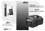
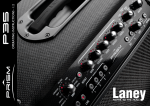
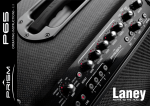
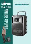
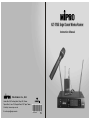
ACT-707SE Single Channel Wireless Receiver
Instruction Manual
Electronics Co., Ltd.
Head office: 814, Pei-Kang Road, Chiayi, 600, Taiwan.
Taipei office: 5, Lane 118, Sung-teh Road, 100, Taipei, Taiwan.
Web-http: //www.mipro.com.tw
E-mail: [email protected]
2CE158
C
ACT SINGLE CHANNEL WIRELESS RECEIVER
CONTENTS
1. INTRODUCTION
ACT SINGLE CHANNEL WIRELESS RECEIVER
1. INTRODUCTION
1
Thanks for choosing the most advanced single channel wireless receiver
system from MIPRO.
2. PARTS NAMES AND FUNCTIONS
2-3
3. INSTALLATION OF THE RECEIVER
4-5
Please read this manual thoroughly for correct operating and optimal
performance.
4. RECEIVER OPERATING PROCEDURES
5
5. 19/2-INCH UNITS RECEIVER INSTALLATION
6-7
6. SWITCHABLE CHANNELS FUNCTIONS
8
7. ACT BUTTON
8
8. CAUTIONS
9
In today's audio professionals, the demand for using lots of multi-channel
wireless microphone systems simultaneously is greatly increasing.
Furthermore, they would like to see professional systems have the capability
of easy frequency agility, more non-interfering channels and interference-free
operation.
ACT-707SE, houses in an international standard 1/2-rack case, has LED
panel that clearly displays channels, RF and AF meters. The system has a
"NOISE" indicator to display. It has an "AutoScan" button to auto search for
non-interference channels with a simple touch of a button. Concurrently, a
simple 1-touch on the ACT button will therefore provides a rapid and precise
channel setting of the transmitter, avoiding possible errors or mechanical
breakdowns. This system is perfect for single system usage under all
professional applications. Space saving, portability, stable performance, easy
to operate and couple with unbeatable prices make it an attractive package.
HANDHELD WIRELESS MICROPHONE
1. PARTS NAMES AND FUNCTIONS
10
2. BATTERY INSERTION
11
3. OPERATING INSTRUCTIONS
11
4. CAUTIONS
11
Included Accessories﹕
①
②
③
④
⑤
BELT PACK TRANSMITTER
1. PARTS NAMES AND FUNCTIONS
16-17
2. OPERATING INSTRUCTIONS
13
3. AF 4-PIN INPUT CONNECTION METHODS
14
4. BATTERY INSERTION
15
5. CAUTIONS
15
0
1
Antenna×2
Audio Output Cable × 1
Rack mount Brackets × 1-pair
AC/DC Adapter × 1
Instruction Manual×1
ACT SINGLE CHANNEL WIRELESS RECEIVER
ACT SINGLE CHANNEL WIRELESS RECEIVER
2. PARTS NAME AND FUNCTIONS
Rear Panel:
Front Panel:
4
7
SCAN
CHANNEL
RF
No.
AF
5
6
NOISE
10
ACT
11
12 13
14 15
16
17
(Fig.2)
1
2
3
8
9
(Fig.1)
(1)
Front Antenna A Input Connector : Allows an optional rear-to-front
Antenna kit for front antenna placement.
(10) Antenna B input Connector: Antenna B connector can be installed with
antenna directly and provides power for antenna booster.
(11) Balanced Audio Output Jack: With Cannon / XLR type connector provides
balanced audio output signal from this jack to the amplifier. Switch
between "LINE" and "MIC" for different purposes.
(2) Power Switch & Indicator: When switch is turned on, red indicator
illuminates to denote normal power status.
(3) ACT Button: To setup microphone frequency to match receiver frequency.
(12) Unbalanced Level Switch: "MIC" selection is for "Microphone-level" output.
"LINE" selection is for "Line-out" level output.
(13) Unbalanced Audio Output Jack: With 1/ 4λ Phone Jack provides audio
output signal from this jack to the amplifier. Switch between "LINE" and
"MIC" for different purposes.
(4) Scan Button: Press once to select receiving channel and autoscan the
whole bandwidth to avoid interference channel.
(5) Channel Indicator: To display system's receiving channel.
(14) Squelch Adjuster: Adjust the squelch level to eliminate the RF noise
interference at receiver stand-by state.
(6) RF Signal Level Indicator: Indicate the RF signal strength received.
(7) Audio Signal Level Indicator: Indicate the audio signal level.
(8) Noise Indicator: To display if the system is under interference.
(15) DC Input Socket: The input socket for 12 Volt DC power. Please note
that the polarity of the central pin in the socket is positive (+).
(9) Front Antenna B Input Connector : Allows an optional rear-to-front
Antenna kit for front antenna placement.
(16) Antenna A Input Connector: Antenna A connector can be installed with
antenna directly and provides power for antenna booster.
(17) Rackmount Bracket: To install the receiver into an EIA 19-inch standard
rack case.
2
3
ACT SINGLE CHANNEL WIRELESS RECEIVER
ACT SINGLE CHANNEL WIRELESS RECEIVER
(c) Balanced Output: Using audio output cables attached with "XLR" or
"Cannon" type, connect one end from the balanced output jacks (11) of the
receiver, and the other end to the "MIC IN" input jack of the mixer or
amplifier, as shown in Fig. 3. (The characteristic of the 3-pin connector is
as shown in Fig. 4
3. INSTALLATION OF THE RECEIVER
1
2
3
1: GND
2: HOT +
3: COLD (Fig.4)
(Fig.3)
1.
Install 2 separate antennas on the antenna sockets (10), (16) on the rear
panel. Illustrated in Fig. 3.
2.
Connecting the power supply: Connect the AC/DC adapter cable to DC
12V INPUT JACK (15), then plug the adapter unit into an appropriate AC
outlet with caution to the correct voltage under both AC outlet and
adapter marked. Illustrated in Fig. 3.
3.
(d) Guitar Output: Using audio output cable attached with "PHONE PLUG" type,
plug one end from the unbalanced output jack of a receiver, and the other
end to the input jack of a guitar amplifier. Switch the Level Switch (12) to
"LINE" position.
4.
Audio Output Connection:
(a) Unbalanced Level Switch (12) Setting Position: When inputs the unbalanced
output of a receiver into "AUX-IN" input jack of a mixer or amplifier or "Electric
Guitar", switch the Level Switch (12) to the right "LINE" position. Low
sensitivity may occur if switch to the wrong position. When input the
unbalanced output of a receiver into the "MIC-IN" input jack of a mixer or
amplifier; switch the Level Switch (12) to the left "MIC" position. Over load
distortion may occur if switch to the wrong position. When using electric guitar,
don't use "MIC" position as it may have generated insufficient level.
(b) Unbalanced Output: Using audio output cable attached with "PHONE PLUG"
type, connect one end from the unbalanced output jack (13) of the receiver,
and theother end to the "LINE-IN" input jack of the amplifier, as shown in Fig.
3.
4
Antenna Socket: The antenna socket provides 8 Volt DC power, which
enable you to pair with MIPRO's antenna booster directly. When the
connecting cable for the antenna is more than 10 meter, it is
recommended to install antenna booster to make up the signal loss
caused by the cable and to ensure the sensitivity of reception.
4. RECEIVER OPERATING PROCEDURES
1.
Turn volume controls of the mixer in use to a minimum setting before turn
on the microphones or transmitters. After switches on the receiver, the
power switch red indicator illuminates to denote normal power status.
2.
Under normal circumstances, the RF indicator lights up when a
microphone or transmitter is turned on near the receiver to indicate the
receiver is ready for normal operation. Once sounds to the microphone
and the AF indicators will glow according to the strength of sound level.
If no LED glows or no sound outputs, the system is not function properly,
thus it must be checked
3.
The microphone output level needs to be adjusted at the amplifier or
mixer. No need to adjust at the receiver itself.
5
ACT SINGLE CHANNEL WIRELESS RECEIVER
ACT SINGLE CHANNEL WIRELESS RECEIVER
5. 19/2-INCH UNITS RECEIVER INSTALLATION
1.
Single half-rack receiver
① Rack mount receiver with optional rack mount kit and fasten with screws on
both sides. (Fig. 5)
3.
On the front panel of the receiver, 4 openings are pre-drilled for instant
installation on the standard 19-inch rack case. (Shows in Fig. 7)
4.
To ensure best reception possible, receiver must be installed at least one
meter above ground. In addition, the distance between transmitter and
receiver must be more than one meter and away from noise. (Shows in
Fig. 8)
(Fig.5)
(Fig.7)
2.
Dual half-rack receivers
① Unfasten the top and bottom screws for each receiver. Push the receivers next
to each other.
② Insert the fixed steel plate between the receiver (top and bottom), align and
fasten the screws tightly as shown in Fig. 6.
③ After both receivers are fixed fasten the rack mount kit on both side of the
receiver as shown on Fig. 6.
(Fig.6)
6
7
(Fig.8)
ACT SINGLE CHANNEL WIRELESS RECEIVER
ACT SINGLE CHANNEL WIRELESS RECEIVER
6. SWITCHABLE CHANNELS FUNCTIONS
7. ACT BUTTON
1. Functions:
1.
Press "ACT" button (3) on the front panel of receiver once and the
system is ready for "ACT" function.
2.
Position the "ACT" marking of the transmitter about 30cm. Towards the
"ACT" button (3) on the receiver as illustrated in below figure.
3.
ACT function will be deactivated automatically once the transmitter
frequency is locked on.
(a)
2.
This system incorporates advanced PLL synthesized oscillator design.
Preprogrammed with 16 switchable frequencies. Allow the user to freely
select any of thepreprogrammed frequencies.
How To Select a Frequency:
(a)
a)
Auto Scanning Frequency Set-up: Holding down the SCAN button (4) for 1
second. Release the button when numeric LED (5) flashes. It will flash a total
of 6 times. To activate the AutoScan function, press the SCAN button once
within these 6 times. An open frequency will automatically be scanned and
saved/locked. *Note AutoScan function works only during numeric LED
flashing and within 6 times.
Pressandhold"SCAN"button
for1second.
b)
SCAN
CHANNEL
RF
No.
AF
ACT
(b)
a)
LEDdisplayflashes.
SCAN
buttonagainand release d)
c) Press"SCAN"
Whendoneitwillautosaved/locked.
willautoscanforanopenfrequency.
SCAN
CHANNEL
RF
No.
AF
ACT
SCAN
CHANNEL
RF
No.
AF
ACT
ACT
CHANNEL
RF
No.
AF
ACT
Manual Frequency Set-up: Holding down the SCAN button (4) for 1 second.
Release the button whennumeric LED (5) flashes. It will flash a total of 6
times. To select any of the 16 frequencies in orderly format, press the SCAN
button and hold until the desired frequency is selected. This frequency will
automatically be saved/locked.
Pressandhold"SCAN"button
for1second.
SCAN
ACT
b)
LEDdisplayflashes.
SCAN
c) Press"SCAN"buttonandhold,
frequencywillchangeeverytwoflashes.
1.
Since the installation of antenna influences the operating efficiency of the
receiver, the most important rule is to minimized the distance between
receiving antenna and microphone as short as possible for better
reception and performance.
2.
The external DC power supply should not be below 12V, otherwise it
would not work properly. If it is over 15V, some components of the
receiver will be damaged due to higher current. Use minimum 1A power
supply.
3.
Antenna socket as 8-volt DC power supply ; please do not short the
circuit of this part!
d) Whendoneitwillautosaved/locked.
SCAN
SCAN
CHANNEL
RF
CHANNEL
RF
CHANNEL
RF
CHANNEL
RF
No.
AF
No.
AF
No.
AF
No.
AF
ACT
8. CAUTIONS
ACT
ACT
3. Change channel when:
(a)
Existing c hannel is being interfered or channel is malfunction.
(b)
Select channel for multiple non-interference usage.
4. Caution while changing channels:
(a)
(b)
When multiple channels are utilized do not change channel to avoid exiting
channel interference.
When numeric knob reaches "_" it indicates an empty channel. Proceed until
a numeric number appears.
8
9
HANDHELD WIRELESS MICROPHONE
HANDHELD WIRELESS MICROPHONE
2. BATTERY INSERTION
1. PARTS NAMES AND FUNCTIONS
(Fig.2)
1
2
3 4
5
6
7
8
9
1.
Unscrew battery cap in a counter-clockwise direction (7).
2.
Insert a 9V battery into the battery compartment according to the correct
polarity as shown in Fig.2. The moment the battery touches the terminals,
the indicator will flash briefly (7). This means the polarity is correct.
However, if no flash occurs, this indicates wrong insertion or that the
battery is dead. Please re-insert the battery according to its correct
polarity or exchange it for a fresh battery.
(Fig.1)
1.
Grille: Protects cartridge, prevents "POP" noise and prevents microphone
from rolling with polygonal shape.
2.
Color Ring: For frequency differentiation.
3.
Battery Status Indicator: Indicates power on / off and the battery status.
When the power switch is turned ON, the red LEDs indicator flashes
briefly, indicating normal battery status. If no flash occurs, it has either no
battery or the battery is discharged or installed incorrectly. If after power
on the indicator stays lighted, it warns that the battery is weak and should
be replaced.
4.
Power On-off Switch: Slide the switch for power " ON " or " OFF ".
5.
Housing: Upper portion to be connected to capsule module and battery.
Internally, it holds transmitter PCB.
6.
Battery Compartment: Designed to accommodate one 9 Volt battery.
7.
Battery Cap: Covers battery in the battery compartment.
8.
Anti-roll Ring: For frequency differentiation.
9.
ACT Signal Receptor: Receiving ACT signal and adjusting frequency
automatically.
3. OPERATING INSTRUCTIONS
1.
When microphone is switched on:
When the power is switched on, the indicator will flash briefly indicating
normal operation.
2.
During Usage:
The AF LED indicator on the receiver will illuminate according to the
audio signal strength from the microphone.
3.
When the microphone is not in use:
Make sure that you turn off the microphone after use to extend the
battery life. Remove the battery from the battery compartment if
microphone is not to be used again for some time. If a rechargeable
battery was used, take it out and recharge it.
4. CAUTIONS
Under normal operation, when receiver and transmitter are paired together
to set frequency, microphone indicator (3) will remain off after ACT setup the
frequency. However, if indicator (3) is flashing, it means receiver and
transmitter are not in the same frequency band. Please check the stickers on
transmitter and receiver to observe if they are sharing the same frequency
bands.
10
11
BELT PACK TRANSMITTER
1. PARTS NAMES AND FUNCTIONS
BELT PACK TRANSMITTER
9.
Battery Compartment and Cover: Accommodates one 9 Volt battery.
10. Detachable Belt Clip: Allows 360 degrees rotating to suit transmitting
angles. To detach simply use a screwdriver at a 45 degree angle to
unfasten. see diagram.
1
2
3
4
5
10
6
7
8
9
ACT
2. OPERATING INSTRUCTIONS
1.
To adjust GT/MT Switch (8), and Gain Control (7), simply push down both
snap locks on the sides of battery cover and flip it backwards to expose
the adjustment panel.
(Fig.1)
1.
AF Input Jack: Connects to either lavaliere or headset microphone. (See
5 ways of connection on AF Input Connections)
2.
Before power on, ascertain if same channel was set up for both receiver
and microphone. If not adjust to same channel accordingly.
2.
Power Switch: Switch to ON position for operation. Switch to OFF position
when not in use.
3.
3.
Battery Status Indicator: Indicates the power on / off and battery status.
(a) When power switch is turned on: The LED indicator flashes briefly,
indicating normal battery status.
(b) When RED light illuminates at either power on or during usage: The
battery level is low, therefore, a new battery replacement is thus
necessary.
The LED indicator flashes briefly when power on indicating normal battery
status. If no flash occurs it has either no battery, the battery is drained or
installed incorrectly. Change accordingly.
4.
Plug the microphone connector into the input jack (1) and tighten the
connector screw by clockwise direction as shown in (Fig. 2).
4.
Transmitting Antenna: 1/ 4 λ transmitting antenna.
5.
Transmitter Housing: Packages the PCB and battery.
6.
ACT Signal Receptor: Receiving ACT signal and adjusting frequency
automatically.
7.
Gain Control: Adjusts the desirous input gain.
8.
GT/MT Level Select Switch: Switch GT position for electric guitar usage
and "Line In". Gain Control is irrelevant for "GT". Switch to "MT" for
condenser microphone or wired microphone. Gain Control works in "MT"
for input sensitivity adjusting.
12
CapsuleConnector
Pleaseaimof
Headset
the fillister
Lavalier
andinsertthe
connector
4
1
3
2
(Fig.2)
13
BELT PACK TRANSMITTER
3. AF 4-PIN INPUT CONNECTION METHODS
4. BATTERY INSTALLATION
4
1
OFF
ON
BATT.
LOW
(1) 2-Wire Electret Condenser Microphone Capsule
1.
Pushing down both snap locks on the sides of battery cover to open
battery cover. Take out the batteries. Fig.3).
2.
Insert a 9V battery into the battery compartment according to the correct
polarity as shown in (Fig. 4). Then push up to close the battery
compartment as shown in (Fig. 4).
3
2
PIN
1
SHIELD
BELT PACK TRANSMITTER
4
AUDIO
2
1
3
2
3
4
(2) 3-Wire Electret Condenser Microphone Capsule
SHIELD PIN
1
2
4
1
AUDIO
BIAS
3
2
3
4
(3) Dynamic Microphone
2
1
SHIELD PIN
1
3
2
4
1
AUDIO
3
2
3
(Fig.3)
(Fig.4)
4
PS: When the microphone is not in use:
Make sure the power of the microphone is off. If the microphone will not
be used for some time, please remove the batteries from the battery
compartment to avoid battery leakage and result in damaged battery
springs and circuit.
(4) Electric Guitar
SHIELD
PIN
1
2
AUDIO
4
1
3
2
3
4
5. CAUTIONS
(5) Line-in (Impedance 8KΩ ATT. 10dB)
SHIELD
AUDIO
Under normal operation, when receiver and transmitter are paired together
to set frequency, microphone indicator (3) will remain off after ACT setup the
frequency. However, if indicator (3) is flashing, it means receiver and
transmitter are not in the same frequency band. Please check the stickers on
transmitter and receiver to observe if they are sharing the same frequency
bands.
PIN
1
2
4
1
3
3
2
4
14
15