1
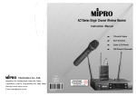
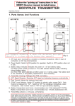
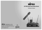
OPERATING MANUAL
Compact, Mobility, Lightweight, BIG SOUND!
MA-101
Wireless Personal PA Amplifier
Electronics Co., Ltd.
Head office:814,Pei-KangRoad,Chiayi,60096,Taiwan.
Taipei office:5,Lane 118, Sung-teh Road,Taipei, 11075, Taiwan.
Web-http://www.mipro.com.tw E-mail: mipro @mipro.com.tw
2 CE2 45
Wireless Portable PA Amplifier
Contents
INTRODUCTION
Wireless Portable PA Amplifier
6
INTRODUCTION---------------------------------------------------- 1
6
6
PARTS NAMES AND FUNCTIONS----------------------------------- 2,3
OPERATING INSTRUCTIONS ---------------------------------------- 3,4
6
CONNECTION TO EXTERNAL AUDIO SOURCES -------------------- 5
6
REPLACING THE MA-101BATTERY --------------------------------- 6
6
SPECIFICATIONS -------------------------------------------------- 7
Thank you for selecting this MIPRO MA-101 Wireless Portable PA
Amplifier system. Before operating, please read this instruction manual
carefully and thoroughly in order to understand the correct operating
procedures to achieve the best results.
Don't be misledbythecompact size of this highly efficient portable PA.
Lightweight and powerful, it can be hand-carried, shoulder-strapped, set on a
flat surface or mounted on a mic stand. Ideal for use in kindergartens or
primary schools, places of worship, presentations, seminars, trade shows,
auctions, tours, political events or any outdoor/indoor location where good
quality speech announcements are a requirement.
Handheld Wireless Microphone
Features
VHF Transmitter
6
PARTS NAMES AND F UNCTIONS - - - - - - - - - - - - - - - - - - - - - - - - - 9
6
BATTERY INSERTION - - - - - - - - - - - - - - - - - - - - - - - - - - - - - - - - - - - 10
6
O P E R A T I N G I N S T R U C T I O N S- - - - - - - - - - - - - - - - - - - - - - - - - - - - - 10
■ Works with one wired and one wireless microphone. Cable-free for mobility.
■ Available in VHF and UHF transmitter works with one or more MA-101 amplifiers.
Ideal for small event PA.
■ Lightweight and truly portable.
■ Powerful and clear sound quality.
■ 8 hours continuous operation per charge from its built-in rechargeable battery.
■ Connects to portable CD/cassette/DVD/MP3 player or other audio sources to
broadcast high quality music over a surprisingly long distance.
■ Compatible with handheld, headworn or lavalier mic and guitar input.
■ Built-in storage compartments.
■ Reduces vocal fatigue.
■ Amplified sound increases attention span and improves comprehension.
■ Handles crowds of up to 200 people.
UHF Transmitter
6
PARTSNAMES A ND F UNCTIONS - - - - - - - - - - - - - - - - - - - - - - - - - - - - 11
6
BATTERY I NSERTION -------------------------------------- 12
6
OPERATINGINSTRUCTIONS -------------------------------- 12
Bodypacks Transmitter
VHF Transmitter
6
PARTSNAMES A ND F UNCTIONS------------------------------------------- 13,14
6
OPERATINGINSTRUCTIONS------------------------------------------------- 14
6
AF 4 - P I N I N P U T CONNECTION METHODS------------------------------- 15
6
BATTERY I NSTALLATION------------------------------------------------------ 16
This system i ncludes the following accessories:
① AC/DC Adapter × 1
UHF Transmitter
6
PARTSNAMES A ND F UNCTIONS------------------------------------------- 17,18
6
OPERATINGINSTRUCTIONS------------------------------------------------- 18
6
AF 4 - P I N I N P U T CONNECTION METHODS------------------------------- 19
6
BATTERY I NSTALLATION------------------------------------------------------ 20
6
NOTE------------------------------------------------------------------------------- 21,22
OptionalSC-10 carrying bag for MA-101
0
1
② Instruction Manual × 1
Wireless Portable PA Amplifier
Wireless Portable PA Amplifier
1. PARTS NAME AND FUNCTIONS
(9)
(10)
(11)
(12)
(13)
(12)
(1)
(14)
Auxiliary Input Jack: Uses a 3.5mm (1/8" "minijack" plug. Accepts external audio
inputs, such as portable cassette/CD/MP3 player.
DC Power Input Jack: Plug into DC charger (supplied) for battery charging. The
inner conductor is positive and should be connected to 18VDC 10%, +2.5A.
Body: Houses all electronic components.
Shoulder Carry Belt: May be stored inside the Battery Compartment.
Battery Compartment: The rechargeable battery is located behind the battery
compartment door.
Microphone Stand Mount: For convenient mounting on a standard 35mm threaded
microphone stand.
2. OPERATING INSTRUCTIONS
(1)
(2)
(4)
WIRELESSLEVEL
POWER
ON
OFF
MIN
(5)
MAX
MICINLEVEL
MAX
CHARGE
(13)
(6)
(7)
LINEOUT
Personal Wireless PA System
a)
b)
c)
d)
(11)
(8)
LINEIN
(9)
DCIN18V
(3)
(10)
Turnon P ower S witch / Volume Control (4). Red light (5) should illuminate.
Turnon wireless transmitter. Green light(5)shouldilluminate.
Adjust volume level (4) clockwise to desiredloudness.
Onewireless microphonecan simultaneously transmit to multipleMA-101 u n its
receiving on the same frequency. However, multiple wireless microphones of the
same frequency cannot transmit to an MA-101 receiver on thatsamefrequency. For
example, if you have b o t h a hand-heldwireless microphoneandabody-pack
transmitter on thesamefrequency, be sure to switch o ff one of the two to avoid
severe interference between them!
(2) Battery ChargingProcedures:
a)
(14)
(1)
(2)
(3)
(4)
(5)
(6)
(7)
Fixed Handle: For convenient carrying by hand.
Speaker: Sound projects in the direction it is pointed.
Mic-In Jack: Accepts a 6.3mm (1/4" plug wired microphone.
Power Switch/Volume Control: Turn clockwise past the click for power-on and
volume control for the wireless microphone.
Power Indicator: Red light illuminates when power is turned on to denote normal
power status. Green light indicates a RF link (it is receiving signal from the
wireless microphone).
Microphone Volume Control: Volume control for the wired microphone.
Charging Indicator:
a)
b)
c)
d)
(8)
b)
c)
d)
Red lightindicates thebatteryis weak a nd needs charging. Charging takes a m inimum
of4hours.
Green blinking light indicates charging i s i n p r o g r e s s .
Solid g reen light indicates the battery is fullycharged.
This system i s equipped withan auto cut-off c harger. When thebattery is weak(red
light), p ower will cut off automatically to avoid any damage that could be caused by a
power over-drain.
Line Out: Allows you to send audio signal (AF) to an external amplifier.
2
e)
f)
3
Please make sure the built-in rechargeable batteries are fully charged before
and after use. The battery itself will gradually self-discharge over a long
period of time. Therefore, if the system will not be used for a long period of
time, please make sure the batteries are fully charged before storing them
properly. The Company warranty DOES NOT apply to over-discharged
batteries; hence, please ensure the batteries are recharged every 3 months.
Simply plug the connector of the supplied DC adapter to the DC 18V Power
Input Jack (10) and plug the other end into any available AC socket.
Charging begins immediately, and will be indicated by a flashing green LED.
If the green LED is not flashing, it may due to excessive power over-drain
and it may take longer for the green LED to flash. This is normal and not
faulty. If, after a while, there is still no flashing green LED, the rechargeable
battery may be faulty.
If a battery replacement is needed, open the battery compartment and
exchange the faulty battery for a new one. Be sure to insert the battery with
the right polarity connection.
The battery is an expendable item and not covered by warranty. Under normal
operation MIPRO offers a one-year limited warranty on the unit ONLY.
If you experience a short operating time after the batteries are fully charged,
it is often an indication of aging batteries. Therefore, the rechargeable
battery should be replaced as soon as possible at your earliest convenience.
Wireless Portable PA Amplifier
Wireless Portable PA Amplifier
(3)
AuxiliaryIn
a) Connecta line-levelsource, such as portable cassette/CD/MP3 playerintothe
Auxinputjack(9).
b) Turn on the PAsystem (4)andadjustvolumeasdesired.
(4)
Installation
a)
b)
c)
(5)
Hand Carrying: Remove the shoulder belt (12) and store in the Battery
Compartment (13) directly above the battery. Use the Fixed Handle for
transport.
Shoulder Carrying: Remove the shoulder belt (12) from the Battery
Compartment (13) and hook the connector around the rod on top of the unit,
between the Fixed Handle and the Speaker.
Mic Stand Mounting: The MA-101 will fit directly on top of a mic stand using
the threaded mount (14) with no additional hardware. Simply align the hole
with the protruding end of the mic stand and thread it on the stand.
c)
d)
Mixer
Amplifier
CassetteRecorder
MP3 PLAYER
CDPLAYER
I-POD
LINEOUT
CableMic.(6.3φConnector)
Cableno:2FA031
MICIN
LINEIN
AVAILABLECABLE FROM MIPRO:
Wired MicrophoneInstructions
a)
b)
(6)
3. CONNECTION TO EXTERNAL AUDIO SOURCES:
MIPRONO: 2FA071
Turn on Power Switch / Volume Control (4). Red light (5) should illuminate.
Plug a wired microphone into the Mic In Jack (3). Turn on the Wired
Microphone Volume Control (6).
Turn clockwise for desired loudness (6).
The MA-101 allows simultaneous usage of both wired and wireless
microphones.
3.5 φ
Allows the user to connect the MA-101 to an external amplifier with high
power output. Connect to the Mic Input or Line Input on the amplifier. Use the
Power Switch / Volume Control (4) to control the volume level.
5
MIPRONO:2FA073
3.5 φ
3.5φ
AF Output
4
MIPRO NO:2FA072
6.3 φ
RCA
3.5φ
Wireless Portable PA Amplifier
Wireless Portable PA Amplifier
5. SPECIFICATIONS:
4. REPLACING THE MA-101 BATTERY
Model
With proper care and charging, it is unlikely that it will be necessary to
replace theMA-101battery for some time. However, there is an access panel
Spec
provided for this purpose. If extendedperiods of use are requiredwithout timeto
recharge thebattery,youmaywish tohave a secondbatteryfullychargedand
ready to install and u s e once theexistingoneisdrained. The battery i s a
standard 12V/2.7Agelcellandisavailable from M I PRO.
CarrierFrequency Range
Oscillation Mode
RX Max. Deviation
Antenna
Sensitivity
Power Output
UHF 600~950MHz
PLL
40KHz
Built In
6dBmV atS/N>70dB
27W(RMS)/4Ω (load)
T.H.D.
Frequency Response
<1%
50Hz-15KHz± 3dB
Built-in w ireless receiver, 1/4 " mic andline-in jacks
Built-in 5 inchhighsensitivity full range speaker
Direct o perationon speaker unit
Audio Input
Speaker
Operation Mode
PowerSupply
3.
4.
5.
6.
Lay the PA system on a flat surface.
Press down on the two fasteners at the top of battery compartment. The
compartment door will now swing down on its hinge.
Remove the interior rear panel of the battery compartment by sliding it up. Use
caution, as the battery may "spring" forward when you release this panel.
Carefully remove the battery.
Insert a fully charged battery, observing the correct polarity. The two terminals on
the battery should be near the top of the battery with the printed side up. This
alignment corresponds with the springs and terminals inside the unit.
Press the battery into the unit, holding it firmly against the springs, while sliding
the rear panel back into space. This may require two hands.
Close the battery compartment door. Lift up on the two fasteners until they "click"
into place.
6
7
12/2.7AH rechargeablebattery and intelligent charger
with 90~260V A C adapter
Charging Time
Operating T i me
Dimensions (m/m)
Weight
4hours(Automatic rechargeablebatterymanagement )
8 hours talktime
285(L) x 160(W), 178(H)
3 Kg s ( with battery)
Exterior Colors
Approvals & Patent
Black
New stylepatents; Telecom and safety regulations approved
Note
1.
2.
MA-101
Variousspecifications o n carrier frequency ranges, maximum
deviations and RFoutputpowercomply w i t h t h e regulations o f
different c ountries.
Handheld Wireless Microphone
Note
Latest modularized microphone structure. Built-in "Piltone & NoiseLock"
dual-squelch circuitry eliminates "pop" interference.
1
2
3
4
5
6
7
(Fig.1)
1. PARTS NAMES AND FUNCTIONS
1. Grille: Protects cartridge and prevents "POP" noise.
2. Battery Status Indicator: Indicates power on / off and the battery status.
When the power switch is turned ON, the red LEDs indicator flashes briefly,
indicating normal battery status. If no flash occurs, it means either no
battery power or the battery is discharged or installed incorrectly. If the
indicator stays lit after powering on, it warns the battery power is low and
should be replaced.
PUSHKNOB UPWARD TO TURN ON AND DOWNWARD TO TURN OFF
TRANSMITTER.
3. Power On-off Switch: Slide the switch for power "ON" or "OFF".
4. Housing: Upper portion is connected to capsule module and battery.
Internally, it holds transmitter PCB.
5. Battery Compartment: Designed to accommodate one 9V battery.
6. Battery Cap: Covers the battery compartment.
7. Anti-roll Ring: For frequency differentiation.
8
9
Handheld Wireless Microphone
Handheld Wireless Microphone
Latest modularized microphone structure. Built-in "NoiseLock" squelch
circuitry eliminates "pop" interference.
2. BATTERY INSERTION
(Fig.2)
1
2
3
4
5
6
7
1. Unscrewbattery cap (6) in a counter-clockwise direction.
(Fig.1)
2. Inser two 1.5V(AA) battery into the battery compartment observing the
correct polarity. The moment the battery touches the terminals of the
compartment, the indicator will flash briefly . This means the polarity is
correct. However, if no flashoccurs, this indicates wrong insertion or
battery is dead. Please re-insert the battery observing its correct polarity or
change to a fresh battery.
1. PARTS NAMES AND FUNCTIONS
3. OPERATING INSTRUCTIONS
2. Battery Status Indicator: Indicates power on / off and the battery status.
When the power switch is turned ON, the red LEDs indicator flashes briefly,
indicating normal battery status. If no flash occurs, it means either no
battery power or the battery is discharged or installed incorrectly. If the
indicator stays lit after powering on, it warns the battery power is low and
should be replaced.
1.
When microphone isswitched on:
At the moment of the power is switched on, theindicator will flash briefly
indicating normal operation.
1. Grille: Protects cartridge and prevents "POP" noise.
PUSHKNOB UPWARD TO TURN ON AND DOWNWARD TO TURN OFF
TRANSMITTER.
(a) When power on:
3. Power On-off Switch: Slide the switch for power "ON" or "OFF".
SIGNAL LED indicator of receiver glows.
4. Housing: Upper portion is connected to capsule module and battery.
Internally, it holds transmitter PCB.
(b) After power on:
More LEDindicators shows received signal strength is strong.
5. Battery Compartment: Designed to accommodate one 9V battery.
(c) During Usage:
6. Battery Cap: Covers the battery compartment.
AUDIO LED displays receivedAF level from the microphone.
(d) When themicrophoneis not in use:
Make sure the power of the microphone is off. Ifthe microphone will
not be used for some time, pleaseremovethe batteriesfrom the
battery compartment to avoid battery leakage and result in damaged
battery springs and circuit. I f a rechargeablebattery was used, take it
out and recharge it.
10
7. Anti-roll Ring: For frequency differentiation.
11
Handheld Wireless Microphone
Bodypack Transmitter
1. PARTS NAMES AND FUNCTIONS
2. BATTERY INSERTION
1
2
3
(Fig.2)
4
1. Unscrewbattery cap (6) in a counter-clockwise direction.
2. Inser two 1.5V(AA) battery into the battery compartment observing the
correct polarity. The moment the battery touches the terminals of the
compartment, the indicator will flash briefly . This means the polarity is
correct. However, if no flashoccurs, this indicates wrong insertion or
battery is dead. Please re-insert the battery observing its correct polarity or
change to a fresh battery.
3. OPERATING INSTRUCTIONS
1.
8
5
6
7
(Fig.1)
When microphone isswitched on:
At the moment of the power is switched on, theindicator will flash briefly
indicating normal operation.
1. AF Input Jack: C onnects to a lavaliere or headset microphone. (See 5 ways
of connection on AF Input Connections)
2. Power Switch: Switch to ON position for operation.Switch to OFF position
when not in use.
(a) When power on:
SIGNAL LED indicator of receiver glows.
3. Battery Status Indicator: Indicates the poweron / off and battery status.
(a) When power switch is turned on: The LED indicator flashes briefly,
indicating normal battery status.
(b) When RED light illuminates at either power on or during usage: The
battery level is low, therefore, a new battery replacement is thus necessary.
4. Transmitter Housing: Packages the PCB andbattery.
(b) After power on:
More LEDindicators shows received signal strength is strong.
(c) During Usage:
AUDIO LED displays receivedAF level from the microphone.
(d) When themicrophoneis not in use:
Make sure the power of the microphone is off. Ifthe microphone will
not be used for some time, pleaseremovethe batteriesfrom the
battery compartment to avoid battery leakage and result in damaged
battery springs and circuit. I f a rechargeablebattery was used, take it
out and recharge it.
12
5. Gain Control: Adjusts thedesirous input gain.
6. GT/MT Level Selector: Switch GT position for electric guitar usage ONLY.
Gain Control is irrelevant for "GT". Switch to "MT" for condenser
microphone, wired microphone. Gain Control works in "MT" for input
sensitivity adjusting.
7. Battery Compartment and Cover: Accommodates two 1.5V(AA) batteries.
13
Bodypack Transmitter
Bodypack Transmitter
8. Detachable Belt Clip: Allows 360 degrees
rotating to suittransmitting angles. To
detach simply u s e a screwdriver at a 45
degree angle to unfasten. see diagram.
3. AF 4-PIN INPUT CONNECTION METHODS
4
3
2
ON
BATT.
LOW
PIN
1
SHIELD
(Fig.2)
1
OFF
(1) 2-Wire Electret Condenser Microphone C apsule
AUDIO
4
2
1
3
2
3
2. OPERATING INSTRUCTIONS
4
1. To adjust volume (5), GT/MT Switch (6), simply p u s h d o w n b o t h snap
locks on the sides ofbattery cover and flip it backwards to expose the
adjustment panel.
(2) 3-Wire Electret Condenser Microphone C apsule
2. The LED indicator flashes briefly when power on indicatingnormal battery
status. If no flash occurs it has either nobattery, the battery is drained or
installed incorrectly. Change accordingly.
SHIELD
PIN
1
2
3
BIAS
3. Adjust Gain Control to desired volume. (Gain Control is irrelevantwhen
switch to G T position).
4. Plug the microphone connector into the input jack (1) and tighten the
connector screw b y clockwise direction as shown in (Fig. 3).
4
1
AUDIO
3
2
4
(3) Dynamic Microphone
2
1
SHIELD
PIN
1
3
2
AUDIO
3
3
2
4
CapsuleConnector
Headset
Lavalier
4
1
Theridgeonthe
connectormustmatchthe
indentationonthesocket
wheninserting. ”
(4) Electric Guitar
SHIELD
PIN
1
2
AUDIO
4
1
3
3
2
4
(5) Line-in (Impedance 8 KΩ ATT. 10dB)
SHIELD
AUDIO
(Fig.3)
PIN
1
2
3
4
14
15
4
1
3
2
(Fig.4)
Bodypack Transmitter
Bodypack Transmitter
4. BATTERY INSTALLATION
1. PARTS NAMES AND FUNCTIONS
1. Pushing down both snap locks on the sides o f battery cover to open battery
cover. Take out the batteries. Fig.5).
2. Insert a two 1.5(AA) batteries into the battery compartment according to the
correct polarityasshown in Fig. 5). Then push up to close the battery
compartment as shown in Fig. 6).
1
8
2
3
4
9
5
6
7
(Fig.5)
(Fig.1)
1. AF Input Jack: C onnects to a lavaliere or headset microphone. (See 5 ways
of connection on AF Input Connections)
2. Power Switch: Switch to ON position for operation.Switch to OFF position
when not in use.
3. Battery Status Indicator: Indicates the poweron / off and battery status.
(a) When power switch is turned on: The LED indicator flashes briefly,
indicating normal battery status.
(b) When RED light illuminates at either power on or during usage: The
battery level is low, therefore, a new battery replacement is thus necessary.
4. Transmitter Housing: Packages the PCB andbattery.
(Fig.6)
PS: When the microphone is not in use:
Make surethepowerofthemicrophoneisoff. Ifthemicrophone will not be
used for some time, please remove the batteries from the battery compartment
to avoid battery leakage and result in damaged battery springs and circuit. If a
rechargeable battery was used, take it out and recharge it.
16
5. Gain Control: Adjusts thedesirous input gain.
6. GT/MT Level Selector: Switch GT position for electric guitar usage ONLY.
Gain Control is irrelevant for "GT". Switch to "MT" for condenser
microphone, wired microphone. Gain Control works in "MT" for input
sensitivity adjusting.
7. Battery Compartment and Cover: Accommodates two 1.5V(AA) batteries.
17
Bodypack Transmitter
Bodypack Transmitter
8. Transmitting Antenna: 1/ 4 λ transmitting
antenna.
3. AF 4-PIN INPUT CONNECTION METHODS
9. Detachable Belt Clip: Allows 360 degrees
rotating to suittransmitting angles. To
detach simply u s e a screwdriver at a 45
degree angle to unfasten. see diagram.
4
3
2
ON
BATT.
LOW
PIN
1
SHIELD
(Fig.2)
1
OFF
(1) 2-Wire Electret Condenser Microphone C apsule
AUDIO
4
2
1
3
2
3
4
2. OPERATING INSTRUCTIONS
(2) 3-Wire Electret Condenser Microphone C apsule
1. To adjust volume (5), GT/MT Switch (6), simply p u s h d o w n b o t h snap
locks on the sides ofbattery cover and flip it backwards to expose the
adjustment panel.
SHIELD
PIN
1
2
2. The LED indicator flashes briefly when power on indicatingnormal battery
status. If no flash occurs it has either nobattery, the battery is drained or
installed incorrectly. Change accordingly.
3
BIAS
3. Adjust Gain Control to desired volume. (Gain Control is irrelevantwhen
switch to G T position).
4
1
AUDIO
3
2
4
(3) Dynamic Microphone
2
4. Plug the microphone connector into the input jack (1) and tighten the
connector screw b y clockwise direction as shown in (Fig. 3).
1
SHIELD
PIN
1
3
2
AUDIO
4
1
3
3
2
4
CapsuleConnector
Headset
Lavalier
Theridgeonthe
connectormustmatchthe
indentationonthesocket
wheninserting. ”
(4) Electric Guitar
SHIELD
PIN
1
2
AUDIO
4
1
3
3
2
4
(5) Line-in (Impedance 8 KΩ ATT. 10dB)
SHIELD
AUDIO
(Fig.3)
PIN
1
2
3
4
18
19
4
1
3
2
(Fig.4)
Bodypack Transmitter
Note
4. BATTERY INSTALLATION
1. Pushing down both snap locks on the sides o f battery cover to open battery
cover. Take out the batteries. Fig.5).
2. Insert a two 1.5(AA) batteries into the battery compartment according to the
correct polarityasshown in Fig. 5). Then push up to close the battery
compartment as shown in Fig. 6).
(Fig.5)
(Fig.6)
PS: When the microphone is not in use:
Make surethepowerofthemicrophoneisoff. Ifthemicrophone will not be
used for some time, please remove the batteries from the battery compartment
to avoid battery leakage and result in damaged battery springs and circuit. If a
rechargeable battery was used, take it out and recharge it.
20
21
NOTE
Disposal
Dispose the unusable device according to valid regulations.
Disposal of spent batteries/accumulators
You are required by law to return all spent batteries. Disposing of used
batteries withdomestic waste is prohibited!
2005-08-13
Batteries / NiCad cells containing toxins are marked by
accompanying symbols that refer to the prohibition of
disposal with domestic waste. The designations for the
decisive heavy metals are: Cd=cadmium, Hg=mercury,
Pb=lead. You may return spent batteries/accumulators free
of charge to the recycling centres, our outlets or anywhere
else where batteries/accumulators are sold.
By doing so, you fulfil the legal requirements and contribute to the
conservation o f o u r environment!
22
23