1
4.2 Mounting the Base in Place
CONTROL PANEL
To install the cabinet, proceed as follows:
A. Hold the base against the mounting surface and mark the
points for drilling (see mounting holes in Figure 2).
B. Drill the mounting holes and insert wall anchors if necessary.
Enter the wires into the base through the wiring knockouts.
Attach the base to the mounting surface with two long screws.
C. Complete the wiring as described in Para. 4.3.
4.3 Wiring (Figures 4 through 7)
A. Connect the relay N.C. (or N.O.) and C terminals of the MCR304 to the selected zone input of the control panel in use.
Note: If the control panel remote control zone input is defined as
E.O.L., use appropriate E.O.L. resistors (see Figure 4).
TROUBLE
ZONE INPUT
G
Z2
12 VDC
OUT
REMOTE CONTROL
ZONE INPUT
Z1
G
E.O.L.
12V
MCR-304
TERMINAL
BLOCK
RELAY
N.C. C N.O.
Figure 6. Wiring All 3 Status Outputs to a Single E.O.L. Zone
CONTROL PANEL
TROUBLE
ZONE INPUT
Z2
N.C.
G
12 VDC
OUT
REMOTE CONTROL
ZONE INPUT
Z1 G
C
RELAY COIL
Figure 4. Using E.O.L. Resistors in the Relay Output Circuit
B. If you wish to separate between status alerts, connect each
status outputs of the MCR-304 (TAMP, LBT and TRB) to a
separate zone input of the control panel, as shown in Figure 5.
NOTE: THESE
CONNECTIONS
ARE CORRECT
IF ZONE INPUTS
ARE DEFINED AS
NORMALLY OPEN
NOTE: ALL THREE
STATUS OUTPUTS
ARE NORMALLY
OPEN. THEY PULL
TO GROUND UPON
OCCURRENCE
OF LOW BATTERY,
TAMPER AND
TROUBLE EVENTS,
RESPECTIVELY.
+Vcc
18Ω
REMOTE CONTROL
ZONE INPUT
12V
MCR-304
TERMINAL
BLOCK
+Vcc
Z1
G
RELAY
N.C. C N.O.
+Vcc
18Ω
12V
RELAY
N.C. C N.O.
Figure 7. Wiring All 3 Status Outputs to a Single N.C. Zone
CONTROL PANEL
12 VDC
OUT
MCR-304
TERMINAL
BLOCK
18Ω
Figure 5. General Wiring Diagram
C. If you prefer to use only one zone input for status alerts,
connect all 3 status outputs of the MCR-304 to a single zone
input of the control panel, as shown in Figures 6 (E.O.L.
option) and 7 (relay option).
4.4 Customizing Your Receiver
After wiring, you must set the relay output operating mode in
accordance with the requirements of your specific application.
Note: The relay output of the MCR-304 may be used for remote
control tasks such as opening / closing a garage door.
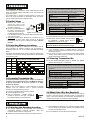
The PULSE / TOGGLE jumper determines the operating mode of
the MCR-304 output relay (Pulse or Toggle):
PULSE MODE
Upon reception of a valid transmission, the output
relay pulls in for as long as the transmission is
received, plus 3 seconds. The relay will drop out
when the “pulse timer” completes its countdown.
Note: If another valid transmission is received during countdown,
the pulse timer will be automatically reset and a new countdown
will begin.
TOGGLE MODE
The output relay changes state each time it receives
a valid transmission. Upon entering a new state, the
toggle circuit is inhibited for 3 seconds, to impose a
3-second interval between states.
Note: If another valid transmission is received during the 3second inhibit period, the inhibit timer will be automatically reset
and a new 3-second period will begin.
5. MISCELLANEOUS COMMENTS
5.1 The Effect of Transmitter Type on
Output Relay Function in the PULSE
Mode
Upon receiving a signal from one or several restoral- reporting
transmitters, the MCR-304 will energize its output relay and will
keep it this way until all transmitters signals restore.
Note: If the system includes restoral reporting transmitters, it is
not recommended to set the MCR-304 to the toggle mode.
5.2 The Effect of Transmitter Type on
the TRB (Trouble) Output
The MCR-304 makes a distinction between supervised and nonsupervised transmitters.
DE3174
Supervised transmitters transmit an “attendance message” at
regular intervals. If such a transmitter fails to send this message
on time, the MCR-304 will activate its TRB (trouble) output.
On the other hand, failure to receive an attendance message
from a transmitter identified as a non-supervised device will be
ignored by the MCR-304.
5.3 Product Limitations
Visonic Ltd. wireless systems are very reliable and are tested to
high standards. However, due to their low transmitting power and
limited range (required by FCC and other regulatory authorities),
there are some limitations to be considered:
A. Receivers may be blocked by radio signals occurring on or
near their operating frequencies.
B. A receiver can only receive one transmitted signal at a time.
C. Wireless equipment should be tested regularly to determine
whether there are sources of interference and to protect
against faults.
3