1
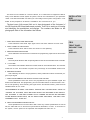
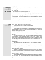
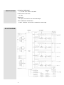
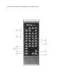
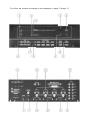
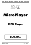
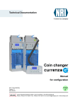
CR10
REMOTE
CONTROL
SYSTEM
CR10
REMOTE
CONTROL
SYSTEM
1.
2.
3.
4.
IMPORTANT
SAFETY
INSTRUCTIONS
THESE
INSTRUCTIONS
ARE TO PROTECT
YOU AND THE
MclNTOSH
INSTRUMENT.
BE SURE TO
FAMILIARIZE
YOURSELF
WITH THEM
Read all instructions - Read the safety and operating instructions before operating the instrument.
Retain Instructions - Retain the safety and operating instructions for future reference.
Heed warnings - Adhere to warnings and operating instructions.
Follow Instructions - Follow all operating and use instructions.
WARNING: TO REDUCE RISK OF FIRE OR ELECTRICAL SHOCK, DO NOT EXPOSE THIS INSTRUMENT TO RAIN OR MOISTURE.
5. Power Sources - Connect the power supply only to the type described in the operating instructions
or as marked on the unit.
6. Power-Cord Protection - Route power-supply cords so that they are not likely to be walked on or
pinched by items placed upon or against them, paying particular attention to cords at plugs,
convenience receptacles, and the point where they exit from the instrument.
7. Ventilation - Locate the instrument for proper ventilation. For example, the instrument should not
be placed on a bed, sofa, rug, or similar surface that may block ventilation openings; or, placed
in a built-in installation, such as a bookcase or cabinet, that may impede the flow of air through
the ventilation openings.
8. Heat - Locate the instrument away from heat sources such as radiators, heat registers, stoves, or
other appliance (including amplifiers) that produce heat.
9. Wall or Cabinet Mounting - Mount the instrument in a wall or cabinet only as described in the owner's
manual.
10. Water and Moisture - Do not use the instrument near water - for example, near a bathtub, washbowl,
kitchen sink, laundry tub, in a wet basement, or near a swimming pool, etc.
11. Cleaning - Clean the instrument by dusting with a dry cloth. Clean the panel with a cloth moistened
with a window cleaner.
12. Object and Liquid Entry - Do not permit objects to fall and liquids to spill into the instrument through
enclosure openings.
13. Nonuse Periods - Unplug the power cord from the AC power outlet when left unused for a long period
of time.
14. Damage Requiring Service - Service must be performed by qualified service personnel when:
A. The power supply cord or the plug has been damaged; or
B. Objects have fallen, or liquid has been spilled into the instrument; or
C. The instrument has been exposed to rain; or
D. The instrument does not appear to operate normally or exhibits a marked change in performance;
or
E. The instrument has been dropped, or the enclosure damaged.
15. Servicing - Do not attempt to service beyond that described in the operating instructions. All other
service should be referred to qualified service personnel.
16. Grounding or Polarization - Do not defeat the inherent design features of the polarized plug. Nonpolarized line cord adaptors will defeat the safety provided by the polarized AC plug.
17. CAUTION: TO PREVENT ELECTRICAL SHOCK DO NOT USE THIS (POLARIZED) PLUG
WITH AN EXTENSION CORD, RECEPTACLE OR OTHER OUTLET UNLESS THE BLADES CAN
BE FULLY INSERTED TO PREVENT BLADE EXPOSURE.
ATTENTION: POUR PREVENIR LES CHOCS ELECTRIQUES PAS UTILISER CETTE
FICHE POLARISEE AVEC UN PROLONGATEUR, UNE PRISE DE COURANT OU UNE AUTRE
SORTIE DE COURANT, SAUF SI LES LAMES PEUVENT ETRE INSEREES A FOND SANS EN
LAISSER AUCUNE PARTIE A DECOUVERT.
The lightning flash with arrowhead, within an equilateral triangle, is intended to alert the
user to the presence of uninsulated "dangerous voltage" within the product's enclosure
that may be of sufficient magnitude to constitute a risk of electric shock to persons.
CAUTION
RISK OF ELECTRIC SHOCK
DO NOT OPEN
CAUTION: TO PREVENT THE RISK OF ELECTRIC SHOCK, DO NOT
REMOVE COVER (OR BACK). NO USER-SERVICABLE PARTS INSIDE.
REFER SERVICING TO QUALIFIED PERSONNEL.
The exclamation point within an equilateral triangle is intended to alert the user to the
presence of important operating and maintenance (servicing) instructions in the literature
accompanying the appliance.
Copyright 1992 © by
Mclnlosh Laboratory Inc.
2
Your decision to own this piece of Mclntosh Stereo Equipment ranks you at the very top among
discriminating music listeners. You now have "The Best". The Mclntosh dedication to "Quality", is
assurance that you will receive thousands of hours of musical enjoyment from this unit.
Please take a short time to read the information in this manual. We want you to be as familiar as
possible with all the features and functions of your new piece of Mclntosh. This will ensure that you
receive all the performance benefits this instrument can offer you, and that it will become a highly valued
part of your home music system.
THANK
YOU
The serial number, purchase date, and Mclntosh Laboratory Service Contract number are
important to you for possible insurance claim or future service. Record this information here.
Serial Number
Purchase Date
Service Contract Number
Upon application, Mclntosh Laboratory provides a Service Contract to the original purchaser.
Your Mclntosh Authorized Service Agency can expedite repairs when you provide the Service Contract with the instrument for repair.
SERVICE CONTRACT
INTRODUCTION
INSTALLATION AND CONNECTIONS
FRONT PANEL PUSHBUTTONS AND DISPLAYS
HR10 HAND HELD REMOTE CONTROLLER PUSHBUTTONS
REAR PANEL CONNECTIONS
4
5, 6
7
7, 8
8, 9
9, 10
AN EXAMPLE OF HOW TO PROGRAM AND OPERATE
A CR10 REMOTE SYSTEM
YOUR REMOTE SYSTEM CONFIGURATION
11
12, 13
SPECIFICATIONS
14
BLOCK DIAGRAM
14
3
TABLE OF
CONTENTS
TAKE ADVANTAGE OF 3 YEARS OF CONTRACT SERVICE . . .
FILL IN THE APPLICATION NOW.
Your CR10 Remote Control System will give you many years of satisfactory performance. If
you have any questions, please contact,
Mclntosh Laboratory Inc.
2 Chambers Street
Binghamton, New York 13903-2699
Phone: 607-723-3512
MclNTOSH
THREE YEAR
SERVICE
CONTRACT
An application for A THREE YEAR SERVICE CONTRACT is included with this manual.
The terms of the contract are:
1. If the instrument covered by this contract becomes defective, Mclntosh will provide all parts,
materials, and labor needed to return the measured performance of the instrument to the
original performance limits free of any charge. The service contract does not cover any
shipping costs to and from the authorized service agency or the factory.
2. Any Mclntosh authorized service agency will repair all Mclntosh instruments at normal
service rates. To receive the free service under the terms of the service contract, the service contract certificate must accompany the instrument when taken to the service agency.
3. Always have service done by a Mclntosh authorized service agency. If the instrument is
modified or damaged as a result of unauthorized repair the service contract will be cancelled. Damage by improper use or mishandling is not covered by the service contract.
4. The service contract is issued to you as the original purchaser. To protect you from
misrepresentation this contract cannot be transferred to a second owner.
5. Units in operation outside the United States and Canada are not covered by the Mclntosh
Factory Service Contract, irrespective of the place of purchase. Nor are units acquired
outside the USA and Canada, the purchasers of which should consult with their dealer
to ascertain what, if any, service contract or warranty may be available locally.
4
A MclNTOSH CR10 REMOTE CONTROL SYSTEM WILL BE CUSTOM DESIGNED
FOR YOUR PARTICULAR NEEDS. THE ACTUAL CAPABILITIES OF EACH SYSTEM WILL
USUALLY BE DIFFERENT. THE PERFORMANCE FEATURES LISTED BELOW INDICATE
THE RANGE OF CAPABILITIES OF THE CR10. YOUR OWN SYSTEM MAY USE ALL OR
ONLY PART OF THE AVAILABLE COMBINATIONS. YOUR MclNTOSH DEALER WILL
ASSIST YOU IN THE PROPER CHOICE OF ACCESSORIES AND COMPONENTS FOR
YOUR PERSONAL SYSTEM REQUIREMENTS.
The Mclntosh CR10 Remote Control system offers a wide variety of performance features
and combinations for an audio and video home entertainment system. The CR10 can accommodate a number of different optional accessories. This will allow you to customize your remote
control system so it will satisfy all your particular needs.
The CR10 system includes the following performance capabilities. Contact your Mclntosh
dealer for any other specific system requirements you may have.
FOUR INDEPENDENT CONTROL AREAS
The CR10 is shipped with two Area Control modules installed, for area one and area two.
Slots are provided to install two additional Model ACM-1 Area Control modules to allow control of two additional remote areas, for a total of four.
SIX PROGRAM SOURCES
Six separate source input signals can be used. These are CD (compact disc player or
changer), TUNER, TAPE 1, TAPE 2, VIDEO and Auxiliary. Any of these six audio input signals
can be selected for any remote location.
PRE-PROGRAMMING CAPABILITY
You can select the source program signal as well as the desired volume setting for each
area before the area amplifier is turned on.
FRONT PANEL LED STATUS INDICATORS
Long life LED indicators show,
1. Which input signal is selected for each remote area,
2. Which remote areas are selected and active,
3. The volume level for each selected remote area.
HR10 HAND HELD REMOTE CONTROLLER
The HR10 allows you to select the signal source and the volume level in a remote area.
You can also perform the following functions on accessory Mclntosh equipment.
Mclntosh Tuner or Tuner Preamplifier:
1. Select AM or FM signals.
2. Seek AM or FM stations, either up or down the frequency range.
3. Select up to eight station presets on AM or FM.
4. Search and audition the PRESET stations.
Mclntosh CD player or changer:
1. Select Play.
2. Select Next Track.
3. Select Previous (Back) Track.
4. Select Stop.
(CD changer only)
5. Select Single Disc.
6. Select the Disc to be played.
5
INTRODUCTION
INTRODUCTION
REMOTE IR SENSOR
The R649 Remote IR sensor can be conveniently installed in a standard single wall outlet
box at a remote location. The HR10 Hand Held Controller can transmit your system selections to this sensor.
REMOTE AREA KEYPAD AND IR SENSOR
A model WK-1 Keypad module can be installed in a double outlet box at a remote location.
System selections can be made with the keypad pushbuttons, as well as with the HR10 Hand
Held Controller which transmits to the IR sensor in the keypad.
REMOTE POWER ON AND MUTE INDICATIONS
On the remote IR sensor, as well as on the keypad, there is a status indicator LED. When
a remote area is turned on, the LED in the IR sensor or keypad lights. If the area has been
muted, the LED will blink on and off.
EXTRA REMOTE SENSOR CAPABILITY
Up to four IR sensors or keypads can be wired in parallel on the same area coaxial line.
AC POWER CONTROL FOR AREA AMPLIFIERS AND ACCESSORIES
A PC-1 AC Power Controller is available to turn AC power on or oft to four area power
amplifiers. The AC outlet for an area power amplifier turns on only when that specific area
is selected.
The Power Controller also has five switched AC outlets for accessory audio equipment and
two switched AC outlets for accessory Video equipment. There are three unswitched AC outlets
that are always on whenever the PC-1 AC cable is connected to a live AC wall outlet. These
outlets could be used for accessories such as a clock, or a Video Tape Recorder programmed to record a TV show when the CR10 system is turned off.
ADD ADDITIONALCR10 UNITS FOR MORE REMOTE AREAS
An optional accessory cable model W103 is available which allows you to connect an additional CR10 into the system. As many as ten CR10 units can be connected in cascade to
allow remote control in a total of 40 areas. Each CR10 added provides an additional four remote
areas.
ADD A FULL FEATURED REMOTE CONTROL CENTER
SUCH AS A MclNTOSH C38 OR C39 PREAMPLIFIER
A Mclntosh Remote Control Center such as the C38 or C39 can be directly interfaced with
the CR10. This component and its power amplifier can then become the main area system.
The CR10 will provide four additional areas.
HOME CONTROL CAPABILITY
Adding the optional HC-1 HOME CONTROLLER allows you to expand AC power control
capability to several other devices in the home. As an example, you could turn lights on or
off, or raise and lower a motorized TV screen.
6
The CR10 can be installed in a custom cabinet, or in a Mclntosh L72 equipment cabinet.
Every CR10 Remote Control System is special, and can be customized for your particular
needs. Your Mclntosh dealer can assist you in the design of the system configuration. Your
dealer is also prepared to do both the installation and connections for you.
INSTALLATION
AND
CONNECTIONS
The back cover of this manual folds out to show photographs of the front pane! of
the CR10 and the HR10 hand held remote controller. Fold it out to assist you In locating
and identifying the pushbuttons and displays. The numbers and letters on the
photographs refer to the information that follows.
1. AREA INPUT SELECTION INDICATORS
These indicators show what input signal source has been selected for each area.
2. AREA POWER ON INDICATORS
These indicators show which areas are turned on and operating.
3. AREA PROGRAM INDICATORS
These indicators show which area is selected for programming input sources and volume
level.
4. SENSOR
The front panel IR sensor that accepts signals from the HR10 hand held remote controller.
5. % VOLUME
The Volume Level indicator shows the volume levels for each selected area. The indicator
reads from 0 to 99. This number is equal to the percentage of the available volume level.
6. PROGRAM SOURCE
After selecting the area to be programmed, these pushbuttons select the desired program input signal.
7. AREA PROGRAMMING FOR SIGNAL SOURCE AND VOLUME
These pushbuttons select the area to be programmed for input SOURCE signal and
desired VOLUME level. This programming can be done either before or after the area is turned on and operating. After selecting the signal source and desired volume, press the area
POWER switch to turn it ON.
PROGRAMMING AN AREA FOR SIGNAL SOURCE AND VOLUME LEVEL PRIOR TO
TURNING ON THE AREA, MUST BE DONE WITHIN TEN SECONDS AFTER SELECTING THE AREA. IF THE AREA POWER IS NOT TURNED ON WITHIN TEN SECONDS
AFTER MAKING SELECTIONS, OR NO SELECTIONS ARE MADE, THE AREA PROGRAMMING WILL TURN OFF.
8. AREA PROGRAMMING POWER ON-OFF
These pushbuttons turn an area ON or OFF. When any of these pushbuttons are turned
ON, the CR10 will turn on and the front panel will be illuminated, if a PC-1 is connected in
the system, the AC power for the specified area amplifier will also turn on.
7
CR10
FRONT PANEL
PUSHBUTTONS
AND
DISPLAYS
CR10 FRONT
PANEL
PUSHBUTTONS
AND DISPLAYS
9. MUTE AREA 1
Press this button to mute all sound in area 1. A CR10 front panel LED will turn on to indicate muting. Press again to restore sound.
10. SYSTEM OFF
This pushbutton turns the entire CR10 system off.
When a CR10 system is turned off, all area programming selections are canceled.
Whenever the CH10 is turned on by an AREA PROGRAMMING POWER ON-OFF
pushbutton, prior to any program selection, the CR10 automatically comes on with
TUNER selected. The turn-on TUNER volume level will be at 50dB below maximum.
11. VOLUME
Press either the up or down button to raise or lower the volume level during normal operation or programming. The VOLUME indicator will change as the volume level changes.
HR10
PUSHBUTTONS
A. CD, TUNER, VIDEO, TAPE 1, TAPE 2 AND Auxiliary
These pushbuttons select a program source input signal.
B. 0 THROUGH 9
These pushbuttons select a station preset on a Mclntosh tuner, or select switching functions available with the optional HC-1 Home Controller. To program the HC-1, you must first
press the HOME button on the HR10.
C. STOP. BACK, NEXT and PLAY
These pushbuttons select the described function on a Mclntosh CD player or changer.
D. HOME
This pushbutton activates the HC-1 Home Controller to allow switching selection of accessory equipment. A CR10 front panel LED will turn on when the HC-1 is selected. You will
have 5 seconds to make each desired selection. 5 seconds after the last selection is made,
the HOME LED turns off. Whenever you wish to use one of the HC-1 selected functions, first
press the HOME button.
E. SYStem OFF
This pushbutton turns the entire CR10 system off. This can be done in any area.
F. POWER
This pushbutton turns power on or off in any specific area. If area 1 is selected, the
entire CR10 system comes on. If areas two, three or four are turned on, only those specific
areas and their amplifiers are turned on.
G. AM, FM, SEARCH and SEEK
The SEEK up or down buttons cause a Mclntosh tuner to move up or down the AM or
FM band and stop at every station. Press the SEARCH button and the Mclntosh tuner will
audition each of the selected station presets.
H. V-AUX, LV, VCR 1, VCR 2, TV
These pushbuttons function when the optional MVS3 Audio Video Switcher is added to
the CR10 system. First, press the Video Button (A), then press a pushbutton to select
8
both the audio and video signals from a TV set, Laserdisc Player or Video recorder 1 or 2,
or Video-Auxiliary.
I. MUTE
The MUTE button mutes the sound in any area where there is an IR sensor.
HR10
PUSHBUTTONS
J. VOLUME
These pushbuttons raise or lower the audio volume in any area during operation or during programming.
A. DATA PORTS
Serial Data Ports are provided for the HC-1 Home Controller, as well as six accessory units.
B. TAPE OUT
Whatever signal source has been programmed and selected in area 1 will appear at
the TAPE OUT jacks.
C. INPUT
Input jacks for program signals from a CD Player or Changer, Tuner, Tape 1, Tape 2, Video
(Audio signal portion) and Auxiliary source.
D. TO NEXT CONTROLLER
Connector for a cable that will allow another CR10 unit to be added to the system. This
cable connects from the TO NEXT CONTROLLER connector on the first CR10 to the CONTROLLER INPUT connector on the next CR10.
E. CONTROLLER INPUT
Connector to accept the cable from a CR10 TO NEXT CONTROLLER output connector
when this particular CR10 is added to the system that already includes one or more CR10 units.
This connector can also be used to add a full featured Mclntosh Remote Control Center
such as a C38 or C39 to a CR10 system. When used with a matching Mclntosh power amplifier
these components can be used as the main area system with its own dedicated loudspeakers.
The CR10 will allow four additional remote areas to be added.
F. AREA 1, 2, 3 and 4
Audio output jacks to feed the remote area power amplifiers.
G. SENSORS
Coaxial outputs to feed to each area Remote IR Sensor or Keypad.
H. TUNER CONTROL
Connector to add an optional model W102 cable to a Mclntosh Tuner or Tuner-Preamplifier.
This allows you to select all tuner functions with the HR10 Hand Held Remote Controller.
I. CD CONTROL
Connector to add an optional model W101 cable to a Mclntosh CD Player or Changer.
This allows you to select four operating functions on the Mclntosh CD Player and six functions on the CD changer with the HR10 Hand Held Remote Controller.
9
REAR PANEL
CONNECTIONS
REAR PANEL
CONNECTIONS
J. POWER CONTROL
Connector to add the cable from a Mclntosh PC-1 Power Controller. This turns on AC
power to each remote area power amplifier, when the area is turned on. It also provides switched AC power for five audio accessories, two video accessories and 3 unswitched outlets.
The unswitched outlets provide AC power as long as the PC-1 power cable is connected to
a live AC wall outlet.
10
SYSTEM CONFIGURATION EXAMPLE:
1. Four areas, with four dedicated power amplifiers and four dedicated pairs of
loudspeakers. An IR wall mount sensor or Keypad in areas two, three and four. The CR10
is in area one.
2. INPUT SIGNAL SOURCES
Mclntosh MR7083 AM-FM Tuner, with control cable.
Mclntosh MCD7007 CD Player, with control cable.
Stereo Cassette Tape Recorder.
3. PC-1 Power Controller connected.
HOW TO SELECT A PROGRAM SOURCE AND VOLUME LEVEL FOR AREA 1
1. Press AREA PROGRAMMING SOURCE VOLUME pushbutton 1.
PERFORM STEPS 2 AND 3 WITHIN 10 SECONDS AFTER STEP 1.
2. Press SOURCE pushbutton for TAPE 1. Then press VOLUME pushbutton to set desired
volume level in area 1.
3. Press POWER ON for area 1.
You have now selected TAPE 1 for Area 1 and turned on the area 1 power amplifier.
HOW TO SELECT A PROGRAM SOURCE AND VOLUME LEVEL FOR AREA 3
1. Press AREA PROGRAMMING SOURCE VOLUME PUSHBUTTON 3.
PERFORM STEPTS 2 AND 3 WITHIN 10 SECONDS AFTER STEP 1.
2. Press SOURCE pushbutton for CD. Then press VOLUME pushbutton to set desired volume
level in area 3.
3. Press POWER ON for area 3.
You have now selected CD to be available in area 3 and turned on the area 3 power
amplifier.
You can now use an HR10 Hand Held Controller in area one or three to select either
the programmed signal, or any of the other available signal sources. You can adjust
the volume level in each area if desired. You can also turn off a specific area and its
amplifier or you can turn off the entire CR10 system. When the entire CR10 system
is turned off, all previous programming is canceled.
You can turn the system on at the CR10 location, or in any remote area. When the
CR10 turns back on, the TUNER is automatically selected at a -50dB volume level.
If a Keypad is installed in a remote area, its pushbuttons allow you to directly select most
of the functions that are possible with the HR10.
11
AN EXAMPLE
OF HOW TO
PROGRAM AND
OPERATE A CR10
REMOTE SYSTEM
YOUR REMOTE
SYSTEM
CONFIGURATION
12
YOUR REMOTE
SYSTEM
CONFIGURATION
13
SPECIFICATIONS
FREQUENCY RESPONSE
+ 0, -0.5dB from 20Hz to 20,000Hz
RATED OUTPUT VOLTAGE
2.5 volts
SENSITIVITY
All Inputs, 0.25 volts for 2.5 volts rated output
TOTAL HARMONIC DISTORTION
0.004% maximum from 20Hz to 20,000Hz at rated output
BLOCK DIAGRAM
14
The letters correspond to the paragraphs on pages 8 and 9
The letters and numbers correspond to the paragraphs on pages 7 through 10
04010100
BE022003