1
MclNTOSH PRODUCT PREVIEWS
As new Mclntosh models are conceived and designs completed, the Engineering Department creates a document called a PRODUCT PREVIEW on each of these
new products. The preview is a complete and detailed description of the new unit.
You will find information on all the important features and their benefits to your
customers. A technical description and performance specifications reveal all the
advanced design performance capabilities of the product.
The following subjects are included in each preview:
1) Promotional Highlights
2) Features and Benefits
3) Performance Specifications
4) Front Panel Information
5) Rear Panel Information
6) Technical Description
7) Front Panel Drawing
8) Rear Panel Drawing
These previews provide valuable information that will help you increase your
knowledge about these exciting new Mclntosh products. The more you know about
a new Mclntosh model, the easier it will be to sell.
Mclntosh wants you to know as much as possible about new models as soon
as possible, so the information in the product previews is created early in the
development time cycle. However, every effort is made to make these product
previews reflect as accurately as possible the characteristics of the production
units you will sell.
039948
BE012004
MClNTOSH LABORATORY INC., 2 CHAMBERS STREET, BiNGHAMTON, NEW YORK 13903
• DC Output Protection
• Regulated Illumination
PRODUCT PREVIEW
• Turn On Delay
MC1000
Power Amplifier
• Half Inch Plate Glass Front Panel
• Modular Construction with Gold Plated Connectors
Project 699
• Optional Mounts for Standard 19" Panel Rack
• Silent Convection Cooling
Contents
Promotional Highlights
Features and Benefits
Performance Specifications
How to Connect Amplifier
Front Panel Controls
Power Guard Operation
Rear Panel Information
Technical Description
Front Panel Drawing
Rear Panel Drawing
1
1
2
2
3
4
5
5-7
8
9
Promotional Highlights
• New Double Balanced Push Pull Design
• Greater than 160 amps Output Current Capability
• Over 400 Joules of Energy Storage
• Gold Plated High Current Output Terminals
• Large Illuminated Peak Responding Output Wattmeter
• Watts Hold
• Ultra Low Distortion
• Wide Power Bandwidth
• Power Guard
• Output Autoformer
• Thermal Protection
• Balanced Input
Features and Benefits
NEW DOUBLE BALANCED PUSH PULL DESIGN
The MC1000 amplifier is fully balanced from
input to speaker output. Two matched amplifiers
operate in PUSH-PULL with their outputs combined in
the "Output Autoformer". Each half of the amplifier
contains complimentary balanced circuitry. The resulting
double balanced configuration cancels virtually all
distortion. This circuit is possible ONLY with the
exclusive "MclNTOSH OUTPUT AUTOFORMER".
HIGH OUTPUT CURRENT
Greater than 160 amperes peak output current
to drive uneven speaker loads. Some poor speaker
designs have input impedances that dip to 1 or 2 ohms
at various frequencies. The MC1000 has the output
current reserve to drive them. Over 4KW output on tone
bursts.
OVER 4 0 0 JOULES OF ENERGY STORAGE
Huge main filter capacitors that guarantee an
excellent signal to noise ratio and the energy storage
necessary for the wide dynamic range that "Digital
Audio" demands.
GOLD PLATED OUTPUT TERMINALS
Mclntosh gold output terminals deliver full power
output to speaker wires from 18GA to 4GA (4GA is
.204 inches in dia. You can connect directly to the
wire. Special lugs or pins that can cause power loss
are not required. Single or Dual "BANANA" plugs may
also be used.
ILLUMINATED PEAK RESPONDING OUTPUT WATTMETER
The Mclntosh MC1000 is the first high power
amplifier to have an Output Wattmeter that responds
MC1000 Product Preview/Page 2
95% full scale to a single cycle tone burst at 2kHz.
Voltage and current output are electronically measured,
multiplied and fed to a special circuit that accelerates
the pointer movement in the upward direction. When
the pointer reaches its peak it pauses only long enough
for the human eye to perceive its position, then drops.
It is almost 10 times faster than a professional VU
meter.
WATTS HOLD
The "Watts Hold" mode for the output meter,
records and displays the highest power output peak of
the source material being amplified.
ULTRA LOW DISTORTION
Distortion so low that it defies measurement, even
with the finest distortion analyzers. At mid-frequencies,
8 ohm load, the distortion meter reads the residual
distortion of the oscillator (.0002%) with or without the
MC1000 in the circuit. This means the amplifier
distortion is lower than the analyzer is capable of
measuring.
WIDE POWER BANDWIDTH
Full power output capability well above and below
the frequencies that can be heard by humans.
POWER GUARD
The exclusive Mclntosh circuit that prevents harsh
sounding clipping and helps protect your speakers from
damage.
THERMAL PROTECTION
Thermal sensors that turn off the AC power if
improper loading or ventilation causes the amplifier to
over heat.
TURN ON DELAY
The MC1000 has a circuit that delays amplifier
operation for about two seconds after turn on. This
prevents pops or thumps generated in other equipment
from causing annoying noises or damaging your
speakers.
BALANCED INPUT
Modern technology has made it possible to build
preamps and amps with the high signal to noise ratio
necessary to reproduce the sound quality present on
compact discs. However, the interconnecting cables
can pick up interference from other equipment or
appliances.
The balanced input on the MC1000
provides a minimum of 40dB (100 times) more
protection against such noise pick up.
OUTPUT AUTOFORMERS
The unequaled expertise of Mclntosh in the
design and manufacture of output transformers is legendary in the Hi Fi industry. In the MC1000 it provides
proper matching for 2, 4 and 8 ohm loads. It protects
your speaker from damage in the event of an output
transistor failure, provides low distortion power transfer
at frequencies well beyond human hearing and delivers
peak output current in excess of 160 amperes.
REGULATED ILLUMINATION
The tremendous peak output power capability
of the MC1000 has made the addition of a circuit that
regulates the brilliance of the panel and meter
illumination necessary. When there are high power
output demands the line voltage may sag however this
new circuit prevents the lights from dimming.
MODULAR CONSTRUCTION
If service should be required, modular
construction makes repairs easier.
Gold plated
connectors are used to assure long life and distortion
free connections even in hostile environments.
SILENT CONVECTION COOLING
New "High Efficiency Circuits", superior
components and large area heatsinks, over 2,800 square
inches, contribute to cool operation. No fans are
required.
Performance Specifications
POWER OUTPUT
1000 watts into an 8, 4 or 2 ohm load is the
minimum sine wave continuous average power output.
The output RMS voltage is:
89.4 across 8 ohms
63.2 across 4 ohms
44.7 across 2 ohms
OUTPUT LOAD IMPEDANCE
Terminals for 8, 4 and 2 ohms.
RATED POWER BAND
20Hz to 20kHz
TOTAL HARMONIC DISTORTION
0.005% maximum harmonic distortion at any
level from 250 milliwatts to rated power output.
DYNAMIC HEADROOM
2.1dB
MCINTOSH LABORATORY INC., 2 CHAMBERS STREET, BlNGHAMTON, NEW YORK 13903
MC1000 Product Preview/Page 3
FREQUENCY RESPONSE
+ 0, -0.25dB from 20Hz to 20kHz
+ 0. -3.0dB from 10Hz to 100kHz
INPUT SENSITIVITY
2.5 volts
A-WEIGHTED SIGNAL TO NOISE RATIO
Balanced, 90dB (120dB below rated output)
Unbalanced, 85dB (115dB below rated output)
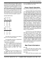
Use lamp cord or wire with similar type of
insulation to connect the speaker to the amplifier. In
all cases, the leads to and from the speaker should be
twin conductor or twisted together. Select the correct
size wire for the wire length from the chart. It is recommended that the DC resistance of the speaker leads be
less than 2.5% of the speaker impedance. Resistance
of the leads should be computed for the length of wire
both to and from the speaker.
MAXIMUM WIRE LENGTH
INTERMODULATION DISTORTION, SMPTE
0.005% maximum if instantaneous peak power
output does not exceed twice the output power rating.
Ratings
WIDE BAND DAMPING FACTOR, 8 ohm output
200
INPUT IMPEDANCE
10,000 ohms
POWER GUARD
Clipping is prevented and THD does not exceed 2%
with up to 14dB overdrive at 1 kHz.
POWER REQUIREMENTS
120 volts, 50/60Hz, 12 amps UL/CSA.
- For 2 ohm Load Wire
Gauge Feet Meters
12
10
8
6
4
15
25
40
60
100
4.6
7.6
12.2
18.3
30.5
- For 4 ohm Load Wire
Gauge Feet Meters
14
12
10
8
6
20
30
50
80
120
6.1
9.1
15.2
24.4
36.6
How to Connect Amplifier
- For 8 ohm Load Wire
Gauge Feet Meters
INPUT
Use a shielded cable to connect the signal from the
preamplifier or signal source to the power amplifier
input. Locate the cable away from speaker leads and
AC power cords. All connections are made on the back
of the MC1000.
16
14
12
10
8
OUTPUT
Selection of the proper gauge wire to connect the
loudspeaker preserves the quality of sound reproduction
for which the loudspeaker has been designed. If undersize wire is used, resistance is added to the amplifier/loudspeaker combination which adversely affects the
performance. Added resistance causes reduction of
damping characteristics, modification of frequency
response and reduction in power output. The output
terminals will accomodate wire gauges 16 through 4.
25
40
60
100
150
7.6
12.2
36.6
30.5
45.7
Wire lengths above represent the wire resistance
equal to 2.5% of the speaker impedance.
For multiple speaker operations, run separate
leads from the amplifier to the speakers.
CONNECTING A LOUDSPEAKER
Use the terminals that match the rated impedance
of your speaker 2, 4 or 8 ohms.
AC POWER
The amplifier AC power cord is plugged into a
MClNTOSH LABORATORY INC., 2 CHAMBERS STREET, BlNGHAMTON, NEW YORK 13903
MC1000 Product Preview/Page 4
120 volt 50/60Hz wall outlet.
The MC1000 draws 12 amperes from the 120 volt
power line when amplifying music or speech. Plug the
AC power cord directly into a wall outlet that has the
at least 12 amperes capacity. Do not plug the MC1000
into an auxiliary AC power outlet on a preamplifier or
other source equipment as this equipment generally
cannot supply 12 amperes. If remote power operation
is desired, use an external power control relay like the
Mclntosh SCR2A, SCR3 or R612 relays. If an extension
cord is required, it must be heavy duty with 14 gauge
wire or heavier.
The amplifier uses only 2 amperes while idling. If
the amplifier is driven to rated output using sine wave
signals, it will draw 20 amperes.
Front Panel Controls
ILLUMINATED OUTPUT WATTMETER
The Mclntosh MC1000 is the first high power
amplifier to have an Output Wattmeter that responds
95% full scale to a single cycle tone burst at 2kHz.
Voltage and current output are electronically measured,
multiplied and fed to a special circuit that accelerates
the pointer movement in the upward direction. When
the pointer reaches its peak it pauses only long enough
for the human eye to perceive its position, then drops.
It is almost 10 times faster than a professional VU
meter.
METER MODE
The METER MODE switch has two positions:
WATTS and HOLD.
WATTS
In the WATTS position, the meter needle indicates
the variations in program loudness. Although the
primary output calibration of the meter is from 10
milliwatts up to 1000 watts, the rated power output
of the MC1000; the additional indications to the right
of the 1000 watts mark, are 2KW & 4 KW. While the
MC1000 cannot reach this power level continuously it
is possible for short interval peaks to considerably
exceed the 1000 watts continuous rating.
slowly return to its rest position (decay rate: 6dB per
minute).
POWER
The POWER switch turns the MC1000 ON or
OFF. If you wish to control the AC power from a
preamplifier control center, leave the switch in the ON
position and use an R612 or SCR-3 power controller.
Power Guard Operation
The Mclntosh Exclusive Protection Circuit
Improved recordings and recording techniques
have imposed higher power demands on today's amplifiers. Poorly designed amplifiers can present music
listeners with a form of harsh unpleasant distortion due
to amplifier overload (hard clipping). Clipping, which
looks and acts like non musical square waves, is caused
when the amplifier is asked to produce more power
output with low distortion than it is capable of or
designed to deliver. Amplifiers, when driven to clipping,
can deliver up to 4 0 % harmonic and intermodulation
distortion that decreases the pleasure and enjoyment
you get from listening. This form of distortion (clipping
signal) also produces extra heat energy which will
damage most speakers.
Mclntosh leadership in
engineering has developed the Power Guard circuit
which - (1) dynamically prevents power amplifiers from
being overdriven into hard clipping - (2) assures that the
amplifier will produce its maximum output without
increased distortion • (3) protects your speaker from
excessive heating. Power Guard is a patented Mclntosh
design (U.S. patent #4048573).
The MC1000 has a circuit that compares the
wave shape of the output signal to the input signal.
If the disparity between the two signals, due to
overdrive, exceeds an average of 0.3% (equivalent to
0.3% total harmonic distortion) an amber POWER
GUARD indicator illuminates. With any further increase
in distortion the POWER GUARD circuit operates to limit
the amplifier input dynamically so that the amplifier
cannot be overdriven. POWER GUARD eliminates
amplifier output clipping. POWER GUARD only operates
when the amplifier is asked to deliver more power than
that for which it was designed.
HOLD
In the HOLD position, the meter needle locks to the
highest power peak in a sequence of peaks. The meter
is driven to maximum power, electronically held there
until a higher peak passes through the amplifier. If no
further peaks are reached the meter needle will very
MclNTOSH LABORATORY INC., 2 CHAMBERS STREET, BlNGHAMTON, NEW YORK 13903
MC1000 Product Preview/Page 5
and low dielectric absorption film capacitors are
used in all critical circuit locations.
Rear Panel Information
OUTPUT
Output connections for impedances of 2, 4 and 8
ohms are provided on secure, screw type, gold plated
terminals.
INPUT
A balanced and unbalanced input are provided.
AC POWER
The MC1000 is rated for 120 volts, 50/60 hertz.
Technical Description
The MC1000 is a power amplifier designed to
operate with a loudspeaker having a nominal impedance
of 2, 4 or 8 ohms.
It features a new circuit design that holds harmonic
distortion far below the amplifiers remarkably low noise
floor.
Only by using special spectrum analysis
measuring techniques is the distortion measurable at
all.
DESIGN PHILOSOPHY
The secret to this performance will sound very
simple, but it is more difficult to carry out than it may
seem. The principle used in the design of the MC1000
was to arrange every stage of voltage or current
amplification to be as linear as possible.
This linear operation is accomplished by using
several different techniques.
1.
Each transistor is selected to have nearly constant
current gain (Beta) over the entire range of currents
at which the transistor must operate.
2. The load impedance presented to each amplification
stage is made to be as uniform as possible for all
signal levels.
3.
The input impedance of stages is increased and
linearized where possible by using emitter degeneration.
4.
Resistors and capacitors in the signal path are
carefully selected to have exceedingly low voltage
coefficients (low change of resistance or reactance
with applied voltage). Precision metal film resistors
5.
Output transistors have matched uniform current
gain, high current gain-bandwidth product, low
output capacitance, and large active-region safe
operating area. These characteristics and the
automatic tracking bias system eliminates crossover distortion. The distortion graphs show
clearly that distortion does not increase at low
power output levels.
OVER 400 JOULES OF ENERGY STORAGE
Huge main filter capacitors are used to guarantee
an excellent signal to noise ratio and the energy storage
necessary for the wide dynamic range that "Digital
Audio" demands.
ILLUMINATED, PEAK RESPONDING OUTPUT
WATTMETER
The MC1000 is the first high power amplifier to
have a REAL OUTPUT WATTMETER. The power output
in WATTS of any amplifier is determined by multiplying
the output voltage (E) by the output current (I), El = W.
Output meters on other amplifiers are only voltmeters.
Output current is not considered. Calibration is in watts
and is based on the false premise that all speakers have
a fixed impedance regardless of frequency. In fact, the
impedance of many poor speakers designs varies by as
much as 4 to 1. For a specific output voltage the
current varies inversely to the speaker impedance. So
if the speaker impedance is lower, the output current
and power are higher. Since Mclntosh can not control
other manufacturers speakers, we decided to provide
extra output current to drive these mismatched low
impedances and to indicate the REAL output power
required to drive them. Therefore the meter circuit in
the MC1000 electronically measures both voltage and
current, multiplies them and displays the REAL OUTPUT
POWER IN WATTS.
Another important feature of these output
wattmeters is their ability to respond 95% full scale to
a single cycle tone burst at 2kHz. After voltage and
current are measured and multiplied, the product is fed
to a special circuit that accelerates the meter pointer
in the upward direction. When it reaches its peak, it
pauses only long enough for the human eye to perceive
its position, then returns to 0. Response is almost 10
times faster than a professional VU meter.
A front panel switch is provided to change the
meter to the WATTS HOLD mode of operation, fast
upward movement of the pointer but greatly increased
MClNTOSH LABORATORY INC., 2 CHAMBERS STREET, BlNGHAMTON, NEW YORK 13903
MC1000 Product Preview/Page 6
HOLD time at the peak of its travel. The highest power
output of the source material is thus recorded.
by 14dB is possible before the output distortion exceeds
2%.
OUTPUT AUTOFORMER
The unequaled expertise of Mclntosh in the design
and manufacture of output transformers is legendary
in the Hi Fi industry. In the MC1000 it provides proper
matching for 2, 4 and 8 ohm loads. It protects your
speaker from damage in the event of an output
transistor failure, provides low distortion power transfer
at frequencies well beyond human hearing and delivers
peak output currents in excess of 160 amperes.
SENTRY MONITOR
All power transistors have limits for the maximum
amount of power they can handle. The MC1000 output
transistors and power supply have been designed to
allow very high current flow into properly matched load
impedances. If, however, a short circuit or very low
value of load impedance is applied to the output of the
MC1000, destructive current levels could be reached
if it was not controlled by the Sentry Monitor circuit.
This circuit senses the dynamic operating time, voltage,
and current of the amplifier output stage and controls
the current flow confining it to nondestructive limits.
Sentry Monitor does not limit the power output available
from the amplifier.
PROTECTION CIRCUITS
Some manufacturers of power amplifiers advertised
that their products do not require or use protection
circuits and that such circuits compromise performance.
Mclntosh Laboratory agrees that diligent measures are
required to allow unrestricted performance, but we also
insist that protection circuits are desirable and necessary
to prevent amplifier or loudspeaker damage due to
abnormal circumstance and that they actually enhance
performance.
The MC1000 incorporates seven
protection circuits to enhance its performance, assure
its reliability and to protect loudspeakers.
POWER GUARD
Power Guard, a unique feature of Mclntosh
amplifiers, assures that the MC1000 will deliver full
power free of clipping distortion. Clipping is caused
when an amplifier is asked to produce more power
output than its design is capable of delivering with low
distortion. Amplifiers that are overdriven may deliver
large quantities of power when they are clipping but
they have more than 4 0 % harmonic distortion. In this
mode, the sound is grossly distorted and the extra
energy content of the clipped signal will damage most
loudspeakers. The Mclntosh Power Guard circuit
protects your ears and your speakers from this kind of
damage.
The Power Guard circuit consists of a waveform
comparator which monitors the wave shape of the
amplifier input and output signals. Normally there is no
disparity between these signals and the comparator
produces no output. When the amplifier is' driven
beyond its maximum power capacity a difference will
develop. If the disparity exceeds 0.3% (equivalent to
0.3% total harmonic distortion) the comparator output
causes the amber power guard indicator to light. If
there is a further increase in the disparity the comparator
output controls an electronic attenuator at the amplifier
input to reduce the amplifier gain, thus holding the
amplifier output to a low distortion value. Overdrive
THERMAL CONTROL
All power transistors have limits for the maximum
amount of heat they can tolerate. The MC1000 uses
a highly efficient amplifying circuit which produces
relatively little heat for the output power produced. The
amplifier has 8 oversized heatsinks to dissipate transistor
generated heat. Natural convection air flow is sufficient
for cool operation. Should the cooling air be blocked
or should the amplifier operating temperature become
too high, thermal cutouts within the amplifier will turn
off the power to the amplifier. When the amplifier has
cooled, it will automatically turn on again.
TURN-ON DELAY
The MC1000 has a turn-on delay circuit that
delays amplifier operation for about 2 seconds after
power turn on. This prevents pops or thumps generated
in other equipment from causing annoying noises or
damaging your loudspeakers.
DIRECT CURRENT FAILURE PROTECTION
The auto transformer protects speakers from
damage in the event of amplifier failure. Should a direct
current component appear in the output it is shunted
by the auto transformer and DC cannot damage the
speaker.
POWER LINE INRUSH PROTECTION
Turn on inrush current is cushioned by
thermistors in the power transformer primary circuit.
A soft start is achieved that eliminates component stress
during turn-on.
CIRCUIT OPERATION
The power output amplifier uses two balanced
stages of voltage amplification followed by three stages
MClNTOSH LABORATORY INC., 2 CHAMBERS STREET, BlNGHAMTON, NEW YORK 13903
MC1000 Product Preview/Page 7
of current amplification. All stages are complimentary
balanced. Even number harmonics are canceled by the
balanced circuits. This means that the amplifying stages
have less total harmonic distortion and less negative
feedback is required to achieve ultra low distortion.
The signal is fed to the input of the balanced
differential stages. Feedback from the amplifier output
is applied to the other inputs. The differential amplifiers
drive a balanced cascade connected voltage amplifier
stage. Current mirrors are also used to improve
bandwidth and linearity.
The cascade voltage amplifiers output feeds
complementary Darlington connected drivertransistors.
These supply the signal to 20 complementary connected
output transistors per side. Ancillary components for
Power Guard, Sentry Monitor, Power Output Meter and
other protection circuits interconnect with the amplifier
circuits. The power supply uses a massive power
transformer, full wave bridge rectifiers. Large filter
capacitors having 400 joules of energy storage. Eight
large heatsinks provide cooling for the 40 output power
transistors.
The mechanical and electrical design of the
MC1000 is the result of the many years of engineering
and manufacturing experience held by the staff at
Mclntosh. This "know how", the meticulous attention
to design and production details, makes the MC1000
the finest amplifier ever produced by Mclntosh
Laboratory.
Issued by Engineering Department:
October 25, 1991
Revised:
October 29, 1991
November 1, 1991
December 2, 1991
January 2 1 , 1992
MClNTOSH LABORATORY INC., 2 CHAMBERS STREET, BlNGHAMTON, NEW YORK 13903
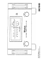
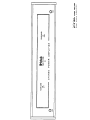
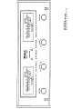
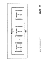
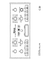
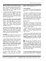
Front Panel Layout
MC1000 POWER AMPLIFIER
McIntosh Laboratory Inc. June 22, 1992
MC1000
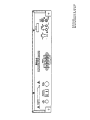
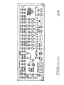
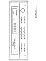
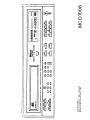
Rear Panel Layout
MC1000 POWER AMPLIFIER
Mclntosh
Laboratory Inc. June 24, 1992
MC1000
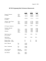
March 24, 1992
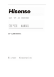
MC1000 Engineering Model Performance Measurements
2 Ohm
4 Ohm
8 Ohm
.0015%
.0013%
.0027%
.0012%
.0010%
.0030%
.0008%
.0009%
.0025%
.0030%
.0030%
.0028%
1135W
1232W
1210W
1175W
1215W
1195W
1218W
1265W
1243W
2.0dB
2.1dB
2.4dB
-.04dB
-.15dB
-.15dB
-.17dB
-.04dB
-.10dB
-.15dB
-.12dB
-.04dB
-.07dB
-.15dB
-.09dB
Peak Current with
IHF Tone Burst
142A
110A
76A
Peak Current
1 MS Tone Burst
183A
136A
96A
Damping Factor - 1 kHz
Damping Factor - 20kHz
28
21
67
43
640
628
Harmonic Distortion
at 1000W
20Hz
1kHz
20kHz
IM Distortion
at 1000W
Maximum Power Output
at .005% THD
20Hz
1kHz
20kHz
IHF Dynamic Headroom
Frequency Response
-Unbalanced
-Balanced
20Hz
20kHz
20Hz
20kHz
Noise - Balanced
Flat
"A"
115dB
122dB
Noise - Unbalanced
Flat
"A"
110dB
117dB
Input Sensitivity
8 ohm output
Balanced
Unbalanced
2.61V
2.57V
Input Balance
1kHz
20kHz
-49dB
-36dB
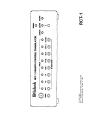
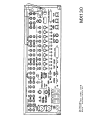
WK-1 KEYPAD
McIntosh Laboratory Inc.
April 24, 1992
WK-1
MClNTOSH LABORATORY INC., 2 CHAMBERS STREET, BlNGHAMTON, NEW YORK 13903
Features and Benefits
PRODUCT PREVIEW
HIGH OUTPUT CURRENT
Greater than 18 amperes peak output current to
drive uneven speaker loads. Some poor speaker designs
have input impedances that dip to 1 or 2 ohms at
various frequencies. The MC7100 has the output current
reserve to drive them.
MC7100
Stereo Power Amplifier
Project 689
OVER 50 JOULES OF ENERGY STORAGE
Huge main filter capacitors that guarantee an
excellent signal to noise ratio and the energy storage
necessary for the wide dynamic range that "Digital
Audio" demands.
Contents
Promotional Highlights
Features and Benefits
Performance Specifications
How to Connect Amplifier
Front Panel Controls
Power Guard Operation
Rear Panel Information
Technical Description
Front Panel Drawing
Rear Panel Drawing
Promotional Highlights
• High Output Current Capability
• Over 50 Joules of Energy Storage
• Gold Plated Output Terminals
• Toroid Power Transformer
• Ultra Low Distortion
1
1
2
2
3
4
4
4-6
7
8
GOLD PLATED OUTPUT TERMINALS
Mclntosh gold plated output terminals will deliver
full output power to all speakers.
ULTRA LOW DISTORTION
Distortion so low that it defies measurement,
even with the finest distortion analyzers. At mid-frequencies, 8 ohm load, the distortion meter reads the
residual distortion of the oscillator (.0002%) with or
without the MC7100 in the circuit. This means the
amplifier distortion is lower than the analyzer is capable
of measuring.
WIDE POWER BANDWIDTH
Full power output capability well above and below
the frequencies that can be heard by humans.
POWER GUARD
The exclusive Mclntosh circuit that prevents
harsh sounding clipping and protects your speakers from
damage.
THERMAL PROTECTION
Thermal sensors that turn off the speakers if
improper loading or ventilation causes the amplifier to
over heat.
• Wide Power Bandwidth
• Power Guard
• Thermal Protection
• DC Output Protection
• Turn On Delay
• Modular Construction
DC OUTPUT PROTECTION
A circuit that turns off the speakers if for any
reason a DC voltage appears at the speaker terminals.
This prevents speaker damage.
TURN ON DELAY
The MC7100 has a circuit that delays amplifier
operation for about two seconds after turn on. This
prevents pops or thumps generated in other equipment
from causing annoying noises or damaging your
speakers.
MC7100 Product Preview/Page 2
MODULAR CONSTRUCTION
If service should be required, modular construction
makes repairs easier.
INTERMODULATION DISTORTION, SMPTE
0.005% maximum if instantaneous peak power
output does not exceed twice the output power rating.
TOROID POWER TRANSFORMER
The toroid permits a low profile design with low
noise and cool operation.
Ratings
Performance Specifications
STEREO POWER OUTPUT
150 watt into 4 ohm loads or 100 watts into 8
ohm loads minimum sine wave continuous average
power output per channel, both channels operating.
The output RMS voltage is:
28.3 across 8 ohms
24.5 across 4 ohms
MONO (Bridged):
300 watts into an 8 ohm load minimum sine wave
continuous average power output, which is 49 volts
RMS.
INPUT IMPEDANCE
20,000 ohms
POWER GUARD
Clipping is prevented and THD does not exceed
2% with up to 15dB overdrive at 1 kHz.
POWER REQUIREMENTS
120 volts, 50/60Hz, 3.0 amps UL/CSA
How to Connect Amplifier
OUTPUT LOAD IMPEDANCE
STEREO
8 or 4 ohms.
INPUT
MONO
8 ohms.
RATED POWER BAND
20Hz to 20kHz
TOTAL HARMONIC DISTORTION
0.005% maximum harmonic distortion at any power
level from 250 milliwatts to rated power output
IHF DYNAMIC HEADROOM
8 ohms. 1 7dB
4 ohms, 2.1dB
FREQUENCY RESPONSE
+ 0, -0.25dB from 20Hz to 20kHz
+ 0, -3.0dB from 10Hz to 100kHz
INPUT SENSITIVITY
1 4 volts (2.5V at gain control center detent)
A-WEIGHTED SIGNAL-TO-NOISE RATIO
95dB (115dB below rated output)
WIDE BAND DAMPING FACTOR
8 ohms, 200
4 ohms, 100
Use shielded cables to connect the signal from
the preamplifier or signal source to the power amplifier
input. To minimize the possibility of hum the shielded
cables should be run parallel to each other or loosely
twisted together. Locate the cables away from speaker
leads and AC power cords. All connections are made
on the back panel of the MC7100.
The left output of the preamplifier should be
plugged into the LEFT INPUT jack of the power amplifier
The right output of the preamplifier should be plugged
into the RIGHT INPUT jack of the power amplifier.
OUTPUT
Selection of the proper gauge wire to connect
the loudspeakers preserves the quality of sound reproduction for which the loudspeakers have been
designed. If undersize wire is used, resistance is added
to the amplifier/loudspeaker combination which
adversely affects the performance. Added resistance
causes reduction of damping characteristics,
modification of frequency response and reduction in
power output.
Use lamp cord or wire with similar type of
insulation to connect the speakers to the amplifier In
MclNTOSH LABORATORY INC., 2
CHAMBERS STREET, BINGHAMTON, NEW YORK
13903
MC7100 Product Preview/Page 3
all cases, the leads to and from the speaker should be
twin conductor or twisted together When using 8 ohm
speakers and for the normally short distances of under
30 feet between the amplifier and speaker, No 18 wire
or larger can be used. For distances over 30 feet
between the amplifier and speaker use larger diameter
wire. Select the correct size wire for the wire length
from the chart It is recommended that the DC resistance of the speaker leads be less than 5% of the
speaker impedance. Up to 10% can be tolerated. Resistance of the leads should be computed for the length
of wire both to and from the speaker or speakers.
MAXIMUM WIRE LENGTH
- For 4 ohm Load Wire
Gauge Feet Meters
18
16
14
12
10
15
25
40
60
100
46
76
122
183
30 5
- For 8 ohm Load •
Wire
Gauge Feet
Meters
18
16
14
12
10
30
50
80
120
200
91
152
24 4
36 6
61 0
Wire lengths above represent the wire resistance
equal to 5% of the speaker impedance
For multiple speaker operations, run separate leads
from the amplifier to the speakers
CONNECTING LOUDSPEAKERS
Connect the leads from the left loudspeaker to the
Left - and + OUTPUT terminals on the MC7100
Connect the leads from the right loudspeaker to the
Right - and + terminals For MONO bridged operation
connect the speaker to the MONO - and + output
terminals
AC POWER
The amplifier AC power cord is plugged into a 120
volt 50/60Hz wall outlet, or into a outlet on the
preamplifier If you wish to control the AC power from
a preamplifier control center, be sure the AC cord of the
MC7100 is plugged into the controlled outlets on the
rear of the preamplifier control center
Power Guard Operation
McIntosh Exclusive Digital Dynamic Protection Circuit
Improved recordings and recording techniques
have imposed higher power demands on today's amplifiers Poorly designed amplifiers can present music
listeners with a form of harsh unpleasant distortion due
to amplifier overload (hard clipping) Clipping, which
looks and acts like non musical square waves, is caused
when the amplifier is asked to produce more power
output with low distortion than it is capable of or
designed to deliver Amplifiers, when driven to clipping,
can deliver up to 40% harmonic and intermodulation
distortion that decreases the pleasure and enjoyment
you get from listening This form of distortion (clipping
signal) also produces extra heat energy which will
damage most speakers
Mclntosh leadership in
engineering has developed the Power Guard circuit
which - (1) dynamically prevents power amplifiers from
being overdriven into hard clipping - (2) assures that the
amplifier will produce its maximum output without
increased distortion - (3) protects your speaker from
excessive heating Power Guard is a patented Mclntosh
design (U S patent #4048573)
The MC7100 has a circuit that compares the
wave shape of the output signal to the input signal
If the disparity between the two signals, due to
overdrive, exceeds an average of 0 3% (equivalent to
0 3% total harmonic distortion) an amber POWER
GUARD indicator illuminates With any further increase
in distortion the POWER GUARD circuit operates to limit
the amplifier input dynamically so that the amplifier
cannot be overdriven POWER GUARD eliminates
amplifier output clipping POWER GUARD only operates
when the amplifier is asked to deliver more power than
that for which it was designed
Rear Panel Information
LEFT GAIN
Use the LEFT GAIN control to ad|ust the output
in the left channel to the desired listening level Turn
the control clockwise to increase the output
RIGHT GAIN
Use the RIGHT GAIN control to adjust the output
MclNTOSH LABORATORY INC., 2 CHAMBERS STREET, BlNGHAMTON, NEW YORK 13903
MC7100 Product Preview/Page 4
at which the transistor must operate
in the right channel to the desired listening level. Turn
the control clockwise to increase the output.
The input sensitivity of the MC7100 is 1.4V with
the gain controls full CW If one desires to match the
2.5 V rating for Mclntosh preamps simply turn each gain
control CCW to the detent position on the control.
2.
The load impedance presented to each
amplification stage is made to be as uniform as
possible for all signal levels.
3.
The input impedance of stages is increased and
linearized where possible by using emitter degeneration.
4.
Resistors and capacitors in the signal path are
carefully selected to have exceedingly low
voltage coefficients (low change of resistance
or reactance with applied voltage). Precision
metal film resistors and low dielectric absorption
film capacitors are used in ail critical circuit
locations.
5
Output transistors have matched uniform current
gain, high current gain-bandwidth product, low
output capacitance, and large active-region safe
operating area. These characteristics and the
automatic tracking bias system eliminates crossover distortion. The distortion graphs show
clearly that distortion does not increase at low
power output levels.
The right gain control also controls the gain in the
MONO mode of operation.
LEFT AND RIGHT OUTPUT
For STEREO operation, output connections for
impedances of 4 to 8 ohms are provided on secure,
screw type, gold plated terminals. Connections for
mono output are marked below the terminals.
INPUT
In the STEREO mode of operation both input jacks
accept signal. For MONO operation use only the Right
input jack and place the MODE switch in MONO.
AC POWER
The MC7100 is rated for 120 volts, 50/60 hertz.
It uses 0 5 amperes when there is no signal output and
up to 5 amperes with both channels delivering rated
power A 5 ampere fuse protects the MC7100 electrically. The AC power outlet provided for auxiliary
equipment is neither fused nor switched.
Technical Description
The MC7100 is a stereo power amplifier designed
to operate with loudspeakers having a nominal impedance of 4 or 8 ohms
It features a new circuit design that holds harmonic
distortion far below the amplifiers remarkably low noise
floor
Only by using special spectrum analysis
measuring techniques is the distortion measurable at
all
DESIGN PHILOSOPHY
The secret to this performance will sound very
simple, but it is more difficult to carry out than it may
seem The principle used in the design of the MC7100
was to arrange every stage of voltage or current
amplification to be as linear as possible
This linear operation is accomplished by using
several different techniques.
1
Each transistor is selected to have nearly constant
current gain (Beta) over the entire range of currents
OVER 50 JOULES OF ENERGY STORAGE
Huge main filter capacitors are used to guarantee
an excellent signal to noise ratio and the energy storage
necessary for the wide dynamic range that "Digital
Audio" demands.
PROTECTION CIRCUITS
Some manufacturers of power amplifiers
advertised that their products do not require or use
protection circuits and that such circuits compromise
performance Mclntosh Laboratory agrees that diligent
measures are required to allow unrestricted performance,
but we also insist that protection circuits are desirable
and necessary to prevent amplifier or loudspeaker
damage due to abnormal circumstance and that they
actually enhance performance
The MC7100
incorporates seven protection circuits to enhance its
performance, assure its reliability and to protect
loudspeakers
POWER GUARD
Power Guard, a unique feature of Mclntosh
amplifiers, assures that each channel of the MC7100
will deliver full power free of clipping distortion Clipping
is caused when an amplifier is asked to produce more
power output than its design is capable of delivering
with low distortion. Amplifiers that are overdriven may
MClNTOSH LABORATORY INC., 2 CHAMBERS STREET, BlNGHAMTON, NEW YORK 13903
MC7100 Product Preview/Page 5
deliver large quantities of power when they are clipping
but they have more than 40% harmonic distortion. In
this mode, the sound is grossly distorted and the extra
energy content of the clipped signal will damage most
loudspeakers. The Mclntosh Power Guard circuit
protects your ears and your speakers from this kind of
damage.
The Power Guard circuit consists of a waveform
comparator which monitors the wave shape of the
amplifier input and output signals. Normally there is no
disparity between these signals and the comparator
produces no output. When the amplifier is driven
beyond its maximum power capacity a difference will
develop. If the disparity exceeds 0.3% (equivalent to
0.3% total harmonic distortion) the comparator output
causes the amber POWER GUARD indicator to light.
If there is a further increase in the disparity the
comparator output controls an electronic attenuator at
the amplifier input to reduce the amplifier gain, thus
holding the amplifier output to a low distortion value.
Overdrive by 14dB is possible before the output
distortion exceeds 2%.
SENTRY MONITOR
All power transistors have limits for the maximum
amount of power they can handle. The MC7100 output
transistors and power supply have been designed to
allow very high current flow into properly matched load
impedances. If, however, a short circuit or very low
value of load impedance is applied to the output of the
MC7100, destructive current levels could be reached
if it was not controlled by the Sentry Monitor circuit.
This circuit senses the dynamic operating time, voltage,
and current of the amplifier output stage and controls
the current flow confining it to nondestructive limits.
Sentry Monitor does not limit the power output available
from the amplifier.
THERMAL CONTROL
All power transistors have limits for the maximum
amount of heat they can tolerate. The MC7100 uses
a highly efficient amplifying circuit which produces
relatively little heat for the output power produced. The
amplifier has oversized heatsinks to dissipate transistor
generated heat. Natural convection airflow is sufficient
for cool operation. Should the cooling air be blocked
or should the amplifier operating temperature become
too high, thermal cutouts within the amplifier will turn
off the speakers. Both POWER GUARD indicators
will light continously to show thermal protection is
operating. When the amplifier has cooled, it will
automatically turn on again.
MclNTOSH LABORATORY INC., 2
TURN-ON DELAY
The MC7100 has a turn-on delay circuit that
delays amplifier operation for about 2 seconds after
power turn on. This prevents pops or thumps generated
in other equipment from causing annoying noises or
damaging your loudspeakers.
DIRECT CURRENT FAILURE PROTECTION
A circuit is provided that turns off the speakers
if for any reason a DC voltage appears at the speaker
terminals. This prevents speaker damage.
POWER LINE INRUSH PROTECTION
Turn on inrush current is cushioned by a
thermistor in the power transformer primary circuit. A
soft start is achieved that eliminates component stress
during turn-on.
CIRCUIT OPERATION
The audio input passes through the gain control
to the power guard attenuator. The output amplifier
follows the attenuator.
The power output amplifier uses two stages of
voltage amplification followed by three stages of current
amplification. All stages are complimentary balanced.
Even number harmonics are canceled by the balanced
circuits. This means that the amplifying stages have
less total harmonic distortion and less negative feedback
is required to achieve ultra low distortion.
The signal is fed to one input of the balanced
differential stage. Feedback from the amplifier output
is applied to the other input. The differential amplifiers
drive a balanced cascode connected voltage amplifier
stage. Current mirrors are also used to improve
bandwidth and linearity.
The cascode voltage amplifier output feeds
complementary Darlington connected driver transistors.
These supply the signal to 4 complementary connected
output transistors per channel. Ancillary components
for Power Guard, Sentry Monitor and other protection
circuits interconnect with the amplifier circuits. The
power supply uses a massive power transformer, full
wave bridge rectifiers and large filter capacitors having
50 joules of energy storage. Large heatsinks provide
cooling for the 8 output power transistors.
The mechanical and electrical design of the
MC7100 is the result of the many years of engineering
and manufacturing experience held by the staff at
Mclntosh. This "know how", the meticulous attention
to design and production details, makes the MC7100
CHAMBERS STREET, BINGHAMTON, NEW YORK
13903
MC7100 Product Preview/Page 6
one of the finest amplifiers ever produced by Mclntosh
Laboratory-
Issued by Engineering Department:
October 29, 1991
Revised:
November 1, 1991
December 17, 1991
January 22, 1992
MclNTOSH LABORATORY INC., 2
CHAMBERS STREET, BINGHAMTON, NEW YORK
13903
Mclntosh
Laboratory
Inc. October 22. 1991
MC7100 STEREO POWER AMPLIFIER
Front Panel Layout
Rear Panel Layout
MC7100 STEREO POWER AMPLIFIER
Mclntosh Laboratory Inc. October 22, 1991
MClNTOSH LABORATORY INC., 2 CHAMBERS STREET, BlNGHAMTON, NEW YORK 13903
Features and Benefits
PRODUCT PREVIEW
Project 654
HIGH OUTPUT-CURRENT
Greater than 50 amperes peak output current to
drive uneven speaker loads. Some poor speaker designs
have input impedances that dip to 1 or 2 ohms at
various frequencies. The MC7150 has the output current
reserve to drive them.
Contents
OVER 58 JOULES OF ENERGY STORAGE
Huge main filter capacitors that guarantee an
excellent signal to noise ratio and the energy storage
necessary for the wide dynamic range that "Digital
Audio" demands.
MC7150
Stereo Power Amplifier
Promotional Highlights
Features and Benefits
Performance Specifications
How to Connect Amplifier
Front Panel Controls
Power Guard Operation
Rear Panel Information
Technical Description
Performance Curves
1
1
2
2
3
4
4
4-7
7-10
Promotional Highlights
• High Output Current Capability
• Over 58 Joules of Energy Storage
• Gold Plated Output Terminals
GOLD PLATED OUTPUT TERMINALS
Mclntosh gold plated output terminals will deliver
full output power to all speakers.
ILLUMINATED PEAK RESPONDING OUTPUT WATTMETERS
The Mclntosh MC7150 is the first high fidelity
power amplifier to have Output Wattmeters that respond
95% full scale to a single cycle tone burst at 2kHz.
Voltage and current output are electronically measured,
multiplied and fed to a special circuit that accelerates
the pointer movement in the upward direction. When
the pointer reaches its peak it pauses only long enough
for the human eye to perceive its position, then drops.
It is almost 10 times faster than a professional VU
meter.
WATTS HOLD
The "Watts Hold" mode for the output meters,
records and displays the highest power output peak of
the source material being amplified.
• Large Illuminated Peak Responding Output Wattmeters
• Watts Hold
• Ultra Low Distortion
• Wide Power Bandwidth
• Power Guard
• Thermal Protection
• DC Output Protection
• Turn On Delay
• Modular Construction
ULTRA LOW DISTORTION
Distortion so low that it defies measurement,
even with the finest distortion analyzers. At mid-frequencies, 8 ohm load, the distortion meter reads the
residual distortion of the oscillator (.0002%) with or
without the MC7150 in the circuit. This means the
amplifier distortion is lower than the analyzer is capable
of measuring.
WIDE POWER BANDWIDTH
Full power output capability well above and below
the frequencies that can be heard by humans.
POWER GUARD
The exclusive Mclntosh circuit that prevents
harsh sounding clipping and protects your speakers from
damage.
MC7150 Product Preview/Page 2
THERMAL PROTECTION
Thermal sensors that turn off the AC power if
improper loading or ventilation causes the amplifier to
over heat.
TURN ON DELAY
The MC7150 has a circuit that delays amplifier
operation for about two seconds after turn on. This
prevents pops or thumps generated in other equipment
from causing annoying noises or damaging your
speakers.
OUTPUT AUTOFORMERS
The unequaled expertise of Mclntosh in the design
and manufacture of output transformers is legendary
in the Hi Fi industry. In the MC7150 they provide proper
matching for 2, 4 and 8 ohm loads. They protect your
speakers from damage in the event of an output
transistor failure, provide low distortion power transfer
at frequencies well beyond human hearing and deliver
peak output current in excess of 53 amperes.
MODULAR CONSTRUCTION
If service should be required, modular construction
makes repairs easier.
Performance Specifications
STEREO POWER OUTPUT
150 watts into 8, 4 or 2 ohm loads is the minimum
sine wave continuous average power output per channel
from 20Hz to 20,000Hz with both channels operating.
The output RMS voltage is:
34.6 across 8 ohms
24.5 across 4 ohms
17.3 across 2 ohms
OUTPUT LOAD IMPEDANCE
STEREO
8, 4 or 2 ohms by connecting to the proper output
terminals.
RATED POWER BAND
20Hz to 20kHz
TOTAL HARMONIC DISTORTION
0.005% maximum harmonic distortion at any power
level from 250 milliwatts to rated power per channel
from 20Hz to 20,000Hz, both channels operating.
INTERMODULATION DISTORTION
0.005% maximum if instantaneous peak per output
MclNTOSH LABORATORY INC., 2
does not exceed twice the output rating per channel,
with both channels operating, for any combination of
frequencies from 20Hz to 20,000Hz.
FREQUENCY RESPONSE (at 1 watt output)
+ 0, -0.25dB from 20Hz to 20kHz
+ 0, -3.0dB from 10Hz to 100kHz
HUM AND NOISE (A-weighted)
110dB below rated output
IHF DYNAMIC HEADROOM
1.8dB
DAMPING FACTOR
Greater than 40
INPUT IMPEDANCE
20,000 ohms
INPUT SENSITIVITY
1.4 volts (2.5V at gain control center detent)
POWER REQUIREMENTS
120 volts, 50/60Hz, .5 to 7 amps
SEMICONDUCTOR COMPLEMENT
62 Silicon Diodes
2 Light Emitting Diodes
72 Bipolar Transistors
7 Integrated Circuits
How to Connect Amplifier
INPUT
Use shielded cables to connect the signal from
the preamplifier or signal source to the power amplifier
input. To minimize the possibility of hum the shielded
cables should be run parallel to each other or loosely
twisted together. Locate the cables away from speaker
leads and AC power cords. All connections are made
on the back panel of the MC7150.
The left output of the preamplifier should be
plugged into the LEFT INPUT jack of the power amplifier.
The right output of the preamplifier should be plugged
into the RIGHT INPUT jack of the power amplifier.
OUTPUT
Selection of the proper gauge wire to connect
the loudspeakers preserves the quality of sound re-
CHAMBERS STREET, BINGHAMTON, NEW YORK
13903
MC7150 Product Preview/Page 3
production for which the loudspeakers have been
designed. If undersize wire is used, resistance is added
to the amplifier/loudspeaker combination which
adversely affects the performance. Added resistance
causes reduction of damping characteristics,
modification of frequency response and reduction in
power output.
Use lamp cord or wire with similar type of insulation
to connect the speakers to the amplifier. In all cases,
the leads to and from the speaker should be twin
conductor or twisted together. When using 8 ohm
speakers and for the normally short distances of under
30 feet between the amplifier and speaker, No. 18 wire
or larger can be used. For distances over 30 feet
between the amplifier and speaker use larger diameter
wire. Select the correct size wire for the wire length
from the chart. It is recommended that the DC resistance of the speaker leads be less than 5% of the
speaker impedance. Up to 10% can be tolerated. Resistance of the leads should be computed for the length
of wire both to and from the speaker or speakers.
MAXIMUM WIRE LENGTH
- For 4 ohm Load Wire
Gauge Feet Meters
18
16
14
12
10
15
25
40
60
100
4.6
7.6
12.2
18.3
30.5
- For 8 ohm Load Wire
Gauge Feet Meters
18
16
14
12
10
30
50
80
120
200
9.1
15.2
24.4
36.6
61.0
Wire lengths above represent the wire resistance
equal to 5% of the speaker impedance.
For multiple speaker operations, run separate leads
from the amplifier to the speakers.
CONNECTING LOUDSPEAKERS
Connect the leads from the left loudspeaker to the
Left and Common OUTPUT terminals on the MC7150.
Connect the leads from the right loudspeaker to the
Right and Common terminals. Use the terminal that
matches the rated impedance of your speakers 1, 4 or
8 ohms.
AC POWER
The amplifier AC power cord is plugged into a
120 volt 50/60Hz wall outlet, or into a outlet on the
preamplifier.
FUSE
A 7-amp slow blow fuse protects the MC7150
circuits. The fuse does not protect additional equipment
connected to the rear panel AC power outlet.
Front Panel Controls
ILLUMINATED OUTPUT WATTMETERS
The Mclntosh MC7150 is the first high fidelity
power amplifier to have Output Wattmeters that respond
95% full scale to a single cycle tone burst at 2kHz.
Voltage and current output are electronically measured,
multiplied and fed to a special circuit that accelerates
the pointer movement in the upward direction. When
the pointer reaches its peak it pauses only long enough
for the human eye to perceive its position, then drops.
It is almost 10 times faster than a professional VU
meter.
LEFT GAIN
Use the LEFT GAIN control to adjust the output
in the left channel to the desired listening level. Turn
the control clockwise to increase the output.
RIGHT GAIN
Use the RIGHT GAIN control to adjust the output
in the right channel to the desired listening level. Turn
the control clockwise to increase the output.
The input sensitivity of the MC7150 is 1.4V with
the gain controls full CW. If one desires to match the
2.5V rating for Mclntosh preamps simply turn each gain
control CCW to the detent position on the control.
METER MODE
The METER MODE switch has two positions:
WATTS and HOLD.
WATTS
In the WATTS position, the meter needle
indicates the variations in program loudness. Although
the primary output calibration of the meters is from 1.5
MClNTOSH LABORATORY INC., 2 CHAMBERS STREET, BlNGHAMTON, NEW YORK 13903
MC7150 Product Preview/Page 4
milliwatts up to 150 watts, the rated power output of
the MC7150; the additional indication to the right of
the 150 watts mark, is 600 watts. While the MC7150
cannot reach this power level continuously it is possible
for short interval peaks to considerably exceed the 150
watts continuous rating.
HOLD
In the HOLD position, the meter needle locks to the
highest power peak in a sequence of peaks. The meter
is driven to maximum power, electronically held there
until a higher peak passes through the amplifier, which
moves the meter needle to a new indication. If no
further peaks are reached the meter needle will very
slowly return to its rest position (decay rate: 6dB per
minute).
The MC7150 has a circuit that compares the
wave shape of the output signal to the input signal.
If the disparity between the two signals, due to
overdrive, exceeds an average of 0.3% (equivalent to
0.3% total harmonic distortion) an amber POWER
GUARD indicator illuminates. With any further increase
in distortion the POWER GUARD circuit operates to limit
the amplifier input dynamically so that the amplifier
cannot be overdriven. POWER GUARD eliminates
amplifier output clipping. POWER GUARD only operates
when the amplifier is asked to deliver more power than
that for which it was designed. While the power output
remains within these limits the POWER GUARD
indicators do not illuminate.
Rear Panel Information
POWER
The POWER switch turns the MC7150 ON or OFF.
The switch does not control the power outlet on the
back panel. If you wish to control the AC power from
a preamplifier control center, leave the switch in the ON
position. Be sure the AC cord of the MC7150 is plugged
into the controlled outlets on the rear of the preamplifier
control center.
OFF: In the OFF position the AC power to the
amplifier is turned off.
LEFT AND RIGHT OUTPUT
For stereo operation, output connections for
impedances of 2, 4 and 8 ohms are provided on secure,
screw type, gold plated terminals.
INPUT
In the stereo mode of operation both input jacks
accept signal.
AC POWER
Power Guard Operation
Mclntosh Exclusive Digital Dynamic Protection Circuit
Improved recordings and recording techniques have
imposed higher power demands on today's amplifiers.
Poorly designed amplifiers can present music listeners
with a form of harsh unpleasant distortion due to
amplifier overload (hard clipping). Clipping, which looks
and acts like non musical square waves, is caused when
the amplifier is asked to produce more power output
with low distortion than it is capable of or designed to
deliver. Amplifiers, when driven to clipping, can deliver
up to 40% harmonic and intermodulation distortion that
decreases the pleasure and enjoyment you get from
listening. This form of distortion (clipping signal) also
produces extra heat energy which will damage most
speakers. Mclntosh leadership in engineering has
developed the Power Guard circuit which - (1) dynamically prevents power amplifiers from being overdriven
into hard clipping - (2) assures that the amplifier will
produce its maximum output without increased
distortion - (3) protects your speaker from excessive
heating. Power Guard is a patented Mclntosh design
(U.S. patent #4048573).
MclNTOSH LABORATORY INC., 2
The MC7150 is rated for 120 volts, 50/60 hertz.
It uses 0.5 amperes when there is no signal output and
up to 7 amperes with both channels delivering rated
power. A 7 ampere fuse protects the MC7150 electrically. The AC power outlet provided for auxiliary
equipment is neither fused nor switched.
Technical Description
The MC7150 is a stereo power amplifier designed
to operate with loudspeakers having a nominal impedance of 2, 4 or 8 ohms.
It features a new circuit design that holds
harmonic distortion far below the amplifiers remarkably
low noise floor. Only by using special spectrum analysis
measuring techniques is the distortion measurable at
all.
DESIGN PHILOSOPHY
The secret to this performance will sound very
simple, but it is more difficult to carry out than it may
seem. The principle used in the design of the MC7150
was to arrange every stage of voltage or current
CHAMBERS STREET, BINGHAMTON, NEW YORK
13903
MC7150 Product Preview/Page 5
amplification to be as linear as possible.
This linear operation is accomplished by using
several different techniques.
1. Each transistor is selected to have nearly constant
current gain (Beta) over the entire range of currents
at which the transistor must operate.
2. The load impedance presented to each amplification
stage is made to be as uniform as possible for all
signal levels.
3.
The input impedance of stages is increased and
linearized where possible by using emitter degeneration.
4.
Resistors and capacitors in the signal path are
carefully selected to have exceedingly low voltage
coefficients (low change of resistance or reactance
with applied voltage). Precision metal film resistors
and low dielectric absorption film capacitors are
used in all critical circuit locations.
5.
Output transistors have matched uniform current
gain, high current gain-bandwidth product, low
output capacitance, and large active-region safe
operating area. These characteristics and the
automatic tracking bias system eliminates crossover distortion. The distortion graphs show clearly
that distortion does not increase at low power
output levels.
OVER 58 JOULES OF ENERGY STORAGE
Huge main filter capacitors are used to guarantee
an excellent signal to noise ratio and the energy storage
necessary for the wide dynamic range that "Digital
Audio" demands.
ILLUMINATED, PEAK RESPONDING OUTPUT
WATTMETERS
The MC7150 is the first high fidelity power amplifier
to have REAL OUTPUT WATTMETERS. The power
output in WATTS of any amplifier is determined by
multiplying the output voltage (E) by the output current
(I), El = W. Output meters on other amplifiers are only
voltmeters.
Output current is not considered.
Calibration is in watts and is based on the false premise
that all speakers have a fixed impedance regardless of
frequency. In fact, the impedance of many poor
speakers designs varies by as much as 4 to 1. For a
specific output voltage the current varies inversely to
the speaker impedance. So if the speaker impedance
is lower, the output current and power are higher. Since
Mclntosh can not control other manufacturers speakers,
we decided to provide extra output current to drive
these mismatched low impedances and to indicate the
REAL output power required to drive them. Therefore
the meter circuit in the MC7150 electronically measures
both voltage and current, multiplies them and displays
the REAL OUTPUT POWER IN WATTS.
Another important feature of these output
wattmeters is their ability to respond 95% full scale to
a single cycle tone burst at 2kHz. After voltage and
current are measured and multiplied, the product is fed
to a special circuit that accelerates the meter pointer
in the upward direction. When it reaches its peak, it
pauses only long enough for the human eye to perceive
its position, then returns to 0. Response is almost 10
times faster than a professional VU meter.
A front panel switch is provided to change the
meters to the WATTS HOLD mode of operation, fast
upward movement of the pointer but greatly increased
HOLD time at the peak of its travel. The highest power
output of the source material is thus recorded.
OUTPUT AUTOFORMERS
The unequaled expertise of Mclntosh in the
design and manufacture of output transformers is legendary in the Hi Fi industry. In the MC7150 they
provide proper matching for 2, 4 and 8 ohm loads. They
protect your speakers from damage in the event of an
output transistor failure, provide low distortion power
transfer at frequencies well beyond human hearing and
deliver peak output currents in excess of 53 amperes.
PROTECTION CIRCUITS
Some manufacturers of power amplifiers
advertised that their products do not require or use
protection circuits and that such circuits compromise
performance. Mclntosh Laboratory agrees that diligent
measures are required to allow unrestricted performance,
but we also insist that protection circuits are desirable
and necessary to prevent amplifier or loudspeaker
damage due to abnormal circumstance and that they
actually enhance performance.
The MC7150
incorporates seven protection circuits to enhance its
performance, assure its reliability and to protect
loudspeakers.
POWER GUARD
Power Guard, a unique feature of Mclntosh
amplifiers, assures that each channel of the MC7150
will deliver full power free of clipping distortion. Clipping
is caused when an amplifier is asked to produce more
power output than its design is capable of delivering
with low distortion. Amplifiers that are overdriven may
deliver large quantities of power when they are clipping
MClNTOSH LABORATORY INC., 2 CHAMBERS STREET, BlNGHAMTON, NEW YORK 13903
MC7150 Product Preview/Page 6
but they have more than 40% harmonic distortion. In
this mode, the sound is grossly distorted and the extra
energy content of the clipped signal will damage most
loudspeakers. The Mclntosh Power Guard circuit
protects your ears and your speakers from this kind of
damage.
The Power Guard circuit consists of a waveform
comparator which monitors the wave shape of the
amplifier input and output signals. Normally there is no
disparity between these signals and the comparator
produces no output. When the amplifier is driven
beyond its maximum power capacity a difference will
develop. If the disparity exceeds 0.3% (equivalent to
0.3% total harmonic distortion) the comparator output
causes the amber power guard indicator to light. If
there is a further increase in the disparity the comparator
output controls an electronic attenuator at the amplifier
input to reduce the amplifier gain, thus holding the
amplifier output to a low distortion value. Overdrive
by 14dB is possible before the output distortion exceeds
2%.
SENTRY MONITOR
All power transistors have limits for the maximum
amount of power they can handle. The MC7150 output
transistors and power supply have been designed to
allow very high current flow into properly matched load
impedances. If, however, a short circuit or very low
value of load impedance is applied to the output of the
MC7150, destructive current levels could be reached
if it was not controlled by the Sentry Monitor circuit.
This circuit senses the dynamic operating time, voltage,
and current of the amplifier output stage and controls
the current flow confining it to nondestructive limits.
Sentry Monitor does not limit the power output available
from the amplifier.
THERMAL CONTROL
All power transistors have limits for the maximum
amount of heat they can tolerate. The MC7150 uses
a highly efficient amplifying circuit which produces
relatively little heat for the output power produced. The
amplifier has 4 oversized heatsinks to dissipate transistor •
generated heat. Natural convection airflow is sufficient
for cool operation. Should the cooling air be blocked
or should the amplifier operating temperature become
too high, thermal cutouts within the amplifier will turn
off the power to the amplifier. When the amplifier has
cooled, it will automatically turn on again.
TURN-ON DELAY
The MC7150 has a turn-on delay circuit that delays
amplifier operation for about 2 seconds after power turn
on. This prevents pops or thumps generated in other
equipment from causing annoying noises or damaging
your loudspeakers.
DIRECT CURRENT FAILURE PROTECTION
The autotransformer protects speakers from
damage in the event of amplifier failure. Should a direct
current component appear in the output it is shunted
by the autotransformer and DC cannot damage the
speaker.
POWER LINE INRUSH PROTECTION
Turn on inrush current is cushioned by
thermistors in the power transformer primary circuit.
A soft start is achieved that eliminates component stress
during turn-on.
CIRCUIT OPERATION
The audio input passes through the gain control
to a preamplifier. The output amplifier is driven by the
preamplifier.
The power output amplifier uses two stages of
voltage amplification followed by three stages of current
amplification. All stages are complimentary balanced.
Even number harmonics are canceled by the balanced
circuits. This means that the amplifying stages have
less total harmonic distortion and less negative feedback
is required to achieve ultra low distortion.
The signal is fed to one input of the balanced
differential stage. Feedback from the amplifier output
is applied to the other input. The differential amplifiers
drive a balanced cascode connected voltage amplifier
stage. Current mirrors are also used to improve
bandwidth and linearity.
The cascode voltage amplifier output feeds
complementary Darlington connected driver transistors.
These supply the signal to 6 complementary connected
output transistors per channel. Ancillary components
for Power Guard, Sentry Monitor, Power Output Meters
and other protection circuits interconnect with the
amplifier circuits. The power supply uses a massive
power transformer, full wave bridge rectifiers. Large
filter capacitors having 58 joules of energy storage.
Four large heatsinks provide cooling for the 12 output
power transistors.
The mechanical and electrical design of the
MC7150 is the result of the many years of engineering
and manufacturing experience held by the staff at
Mclntosh. This "know how", the meticulous attention
to design and production details, makes the MC7150
MClNTOSH LABORATORY INC., 2 CHAMBERS STREET, BlNGHAMTON, NEW YORK 13903
MC7150 Product Preview/Page 7
one of the finest amplifiers ever produced by Mclntosh
Laboratory.
Issued by Engineering Department:
December 6, 1990
Revised: January 4, 1991
October 20, 1991
MclNTOSH LABORATORY INC., 2
CHAMBERS STREET, BINGHAMTON, NEW YORK
13903
Front Panel Layout
MC7150 POWER AMPLIFIER
Mclntosh Laboratory Inc. November 14, 1991
MClNTOSH LABORATORY INC., 2 CHAMBERS STREET, BlNGHAMTON, NEW YORK 13903
•
Turn On Delay
PRODUCT PREVIEW
•
Balanced Inputs
MC7300
STEREO
POWER AMPLIFIER
•
Modular Construction
•
Output Autoformers
FEATURES AND BENEFITS
Project 638
HIGH OUTPUT CURRENT
Greater than 85 amperes peak output current to
drive uneven speaker loads. Some poor speaker
designs have input impedances that dip to 1 or 2
ohms at various frequencies. The MC7300 has the
output current reserve to drive them.
Contents
Promotional Highlights
Features and Benefits
Performance Specifications
Front Panel Controls
Power Guard Operation
Rear Panel Information
Technical Description
.
1
. .. 1
2
3
4
4
5-7
PROMOTIONAL HIGHLIGHTS
OVER 227 JOULES OF ENERGY STORAGE
Huge main filter capacitors that guarantee an
excellent signal to noise ratio and the energy storage
necessary for the wide dynamic range that "Digital
Audio" demands.
50 AMP GOLD PLATED OUTPUT TERMINALS
An exclusive Mclntosh gold plated output
terminal that will deliver full output power to speaker
wires from 16GA to 4GA. 4 gauge wire is .204
inches in diameter, nearly 1/4 of an inch. ("Monster
Cable" is 8GA, .128 inches in dial. You can connect
directly to the wire. Special lugs or pins that can
cause power loss are not required.
•
High Output Current Capability
•
Over 227 Joules of Energy Storage
•
50 Amps Gold plated Output Terminals
•
Large Illuminated
Wattmeters
•
Watts Hold
•
Ultra Low Distortion
•
Wide Power Bandwidth
•
Power Guard
The Mclntosh MC7300 is the first high power
amplifier to have Output Wattmeters that respond
95% full scale to a single cycle tone burst at 2kHz.
Voltage and current output are electronically
measured, multiplied and fed to a special circuit that
accelerates the pointer movement in the upward
direction. When the pointer reaches its peak it
pauses only long enough for the human eye to
perceive its position, then drops. It is almost 10
times faster than a professional VU meter.
•
Thermal Protection
WATTS HOLD
•
DC Output Protection
The "Watts Hold" mode for the output meters,
records and displays the highest power output peak
of the source material being amplified.
•
Regulated Illumination
Peak
Responding
ILLUMINATED PEAK RESPONDING OUTPUT
WATTMETERS
Output
MC7300 Product Preview/Page 2
ULTRA LOW DISTORTION
Distortion so low that it defies measurement,
even with the finest distortion analyzers At midfrequencies, 8 ohm load, the distortion meter reads
the residual distortion of the oscillator ( 0002%) with
or without the MC7300 in the circuit. This means
the amplifier distortion is lower than the analyzer is
capable of measuring
BALANCED INPUTS
Modern technology has made it possible to build
preamps and amplifiers with the high signal to noise
ratio necessary to reproduce the sound quality
present on compact discs
However, the
interconnecting cables can pick-up electrical
interference from other equipment or appliances The
balanced inputs on the MC7300 provide a minimum
of 40dB more protection against such noise pick-up
WIDE POWER BANDWIDTH
Full power output capability well above and
below the frequencies that can be heard by humans
POWER GUARD
The exclusive Mclntosh circuit that prevents
harsh sounding clipping and protects your speakers
from damage
THERMAL PROTECTION
Thermal sensors that turn off the AC power if
improper loading or ventilation causes the amplifier to
over heat
REGULATED ILLUMINATION
The tremendous peak output power capability of
the MC7300 has made the addition of a circuit that
regulates the brilliance of the illumination necessary
When there are high power output demands, the line
voltage may sag, however this new circuit prevents
the panel lights from dimming
TURN ON DELAY
The MC7300 has a circuit that delays amplifier
operation for about two seconds after turn on This
prevents pops or thumps generated in other
equipment from causing annoying noises or damaging
your speakers
OUTPUT AUTOFORMERS
The unequaled expertise of Mclntosh in the
design and manufacture of output transformers is
legendary in the Hi Fi industry In the MC7300 they
provide proper matching for 2, 4 and 8 ohms loads in
stereo and 1,2,4,8 and 16 ohms in mono They
protect your speakers from damage in the event of an
output transistor failure, provide low distortion power
transfer at frequencies well beyond human hearing
and deliver peak output currents in excess of 85
amperes
MODULAR CONSTRUCTION
If service should be required,
construction makes repairs easier
modular
PERFORMANCE SPECIFICATION
STEREO POWER OUTPUT
300 watts into 8, 4 or 2 ohm loads is the
minimum sine wave continuous average power output
per channel from 20Hz to 20,000Hz with both
channels operating The output RMS voltage is
49 0 across 8 ohms
34 6 across 4 ohms
24 5 across 2 ohms
MONO-BRIDGE POWER OUTPUT
600 watts into a 16, 8 or 4 ohm load in the
minimum sine wave continuous average power output
from 20Hz to 20,000Hz The output RMS voltage is
98 0 across 16 ohms
69 3 across 8 ohms
49 0 across 4 ohms
MONO-PARALLEL POWER OUTPUT
600 watts into a 4, 2 or 1 ohm load is the
minimum sine wave continuous average power output
from 20Hz to 20,000Hz The output RMS voltage is
49 across 4 ohms
34 6 across 2 ohms
24 5 across 1 ohm
OUTPUT LOAD IMPEDANCE
STEREO
8, 4 or 2 ohms by connecting to the proper
output terminals
MONO
16 8, 4, 2 or 1 ohms by connecting to proper
output terminals
RATED POWER BAND
20Hz to 20kHz
MclNTOSH LABORATORY INC., 2 CHAMBERS STREET, BINGHAMTON, NEW YORK 13903
MC7300 Product Preview/Page 3
TOTAL HARMONIC DISTORTION
STEREO
0 005% maximum harmonic distortion at any
power level from 250 milliwatts to rated power per
channel from 20Hz to 20,000Hz, both channels
operating
MONO
0 005% maximum harmonic distortion at any
power level from 250 milliwatts to rated power from
20Hz to 20,000Hz
INTERMODULATION DISTORTION
STEREO
0 005% maximum if instantaneous peak per
output does not exceed twice the output rating per
channel, with both channels operating, for any
combination of frequencies from 20Hz to 20 000Hz
MONO
0 005% maximum if instantaneous peak power
output does not exceed twice the output rating for
any combination of frequencies from 20Hz to
20,000Hz
FREQUENCY RESPONSE (at one watt output)
+ 0, -0 25dB from 20Hz to 20kHz
+ 0, -3 0dB from 10Hz to 100kHz
HUM AND NOISE (A-weighted)
105dB below rated output
IHF DYNAMIC HEADROOM
1 9dB
DAMPING FACTOR
Greater than 40
INPUT IMPEDANCE
20,000 ohms Unbalanced
40,000 ohms Balanced
INPUT SENSITIVITY
Switchable for either 1.4 or 2.5 volts
POWER REQUIREMENTS
120 volts, 50/60Hz, 0.6 to 13 amperes
MclNTOSH LABORATORY INC., 2
FRONT PANEL INFORMATION
ILLUMINATED OUTPUT WATTMETERS
The Mclntosh MC7300 is the first high power
amplifier to have Output Wattmeters that respond
95% full scale to a single cycle tone burst at 2kHz
Voltage and current output are electronically
measured, multiplied and fed to a special circuit that
accelerates the pointer movement in the upward
direction
When the pointer reaches its peak it
pauses only long enough for the human eye to
perceive its position, then drops It is almost 10
times faster than a professional VU meter
POWER GUARD
This exclusive Mclntosh circuit prevents harsh
sounding clipping and protects your speakers from
damage The MC7300 has a circuit that compares
the wave shape of the output signal to the input
signal If the disparity between the two signals, due
to overdrive, exceeds an average of 0 3% (equivalent
to 0 3% total harmonic distortion) an amber POWER
GUARD indicator illuminates
With any further
increases in distortion the POWER GUARD circuit
operates to limit the amplifier input dynamically so
that the amplifier cannot be overdriven
POWER
GUARD eliminates amplifier output clipping POWER
GUARD only operates when the amplifier is asked to
deliver more power than that for which it was
designed While the power output remains within
these limits the POWER GUARD indicators do not
illuminate
LEFT GAIN
Use the LEFT GAIN control to adjust the output
in the left channel to the desired listening level Turn
the control clockwise to increase the output
RIGHT/MONO GAIN
Use the RIGHT/MONO GAIN control to adjust
the output in the right channel to the desired listening
level Turn the control clockwise to increase the
output
When connected for monophonic operation use
the RIGHT/MONO GAIN to adjust the total output to
the desired listening level The rear panel MODE
SWITCH must be in the MONO-BRIDGE or MONO
PARALLEL POSITION
CHAMBERS STREET, BINGHAMTON, NEW YORK
13903
MC7300 Product Preview/Page 4
METER MODE
The METER MODE switch has two positions:
WATTS and HOLD.
WATTS
In the WATTS position, the meter needle
indicates the variations in program loudness.
Although the primary output calibration of the meters
is from 3.0 milliwatts up to 300 watts, the rated
power output of the MC7300; the additional
indications to the right of the 300 watts mark, are
600 and 1200 watts. While the MC7300 cannot
reach this power level continuously it is possible for
short interval peaks to considerably exceed the 300
watts continuous rating.
HOLD
In the HOLD position, the meter needle locks to
the highest power peak in a sequence of peaks. The,
meter is driven to maximum power, electronically held
there until a higher peak passes through the amplifier,
which moves the meter needle to a new indication.
If no further peaks are reached the meter needle will
very slowly return to its rest position (decay rate: 6dB
per minute).
POWER
The POWER switch turns the MC7300 ON or
OFF. The switch does not control the power outlet
on the back panel. If you wish to control the AC
power from a preamplifier control center, leave the
switch in the ON position. Be sure the AC cord of
the MC7300 is plugged into the switched outlets on
the rear of the preamplifier control center.
POWER GUARD
OPERATION - McIntosh Exclusive Digital
Dynamic Protection Circuit
Improved recordings and recording techniques
have imposed higher power demands on today's
amplifiers. Poorly designed amplifiers can present
music listeners with a form of harsh unpleasant
distortion due to amplifier overload (hard clipping).
Clipping, which looks and acts like non musical
square waves, is caused when the amplifier is asked
to produce more power output with low distortion
than it is capable of or designed to deliver.
Amplifiers, when driven to clipping, can deliver up to
40% harmonic and intermodulation distortion that
decreases the pleasure and enjoyment you get from
listening. This form of distortion (clipping signal) also
produces extra heat energy which will damage most
speakers. Mclntosh leadership in engineering has
developed the Power Guard circuit which - (1)
dynamically prevents power amplifiers from being
overdriven into hard clipping - (2) assures that the
amplifier will produce its maximum output without
increased distortion - (3) protects your speaker from
excessive heating. Power Guard is a patented
Mclntosh design (U.S. patent #4048573).
The MC7300 has a circuit that compares the
wave shape of the output signal to the input signal.
If the disparity between the two signals, due to
overdrive, exceeds an average of 0.3% (equivalent to
0.3% total harmonic distortion) an amber POWER
GUARD indicator illuminates.
With any further
increase in distortion the POWER GUARD circuit
operates to limit the amplifier input dynamically so
that the amplifier cannot be overdriven. POWER
GUARD eliminates amplifier output clipping. POWER
GUARD only operates when the amplifier is asked to
deliver more power than that for which it was
designed. While the power output remains within
these limits the POWER GUARD indicators do not
illuminate.
REAR PANEL INFORMATION
MODE SWITCH
The MC7300 will operate in three modes,
Stereo, Mono Bridge, and Mono Parallel.
INPUT LEVEL
The input sensitivity of the MC7300 is 1.4
volts or 2.5V depending on the position of the INPUT
sensitivity switch. For the best signal to noise ratio
when using Mclntosh source equipment, place the
INPUT sensitivity switch in the 2.5V position and the
front panel LEFT GAIN and RIGHT/MONO GAIN
controls in the fully clockwise position. If more gain
is desired, the 1.4V position may be used. All
Mclntosh preamplifiers have been designed to deliver
2.5 volts output with rated input.
For source
equipment other than Mclntosh, set the switch in the
position nearest to stated output rating of the source
equipment.
MClNTOSH LABORATORY INC., 2 CHAMBERS STREET, BlNGHAMTON, NEW YORK 1 3 9 0 3
MC7300 Product Preview/Page 5
INPUT
Both LEFT and RIGHT UNBALANCED and
BALANCED input connectors function in the stereo
mode of operation In the mono mode of operation
only the RIGHT/MONO input in either UNBALANCED
or BALANCED accepts signal In mono the LEFT
channel input connectors are disconnected
Modern technology has made it possible to build
preamps and amplifiers with the high signal to noise
ratio necessary to reproduce the sound quality
present on compact discs
The interconnecting
cables can pick up electrical interference from other
equipment or appliances The balanced inputs on the
MC7300 provide a minimum of 40dB more protection
against such noise pick-up
LEFT AND RIGHT OUTPUT TERMINALS
Mclntosh 50 ampere gold plated output terminals
will deliver full output power to speaker wires from
18GA to wire that is 1 /4 of an inch in diameter The
MC7300 has greater than 85 amperes peak output
current to drive speakers whose impedance varies
from 16 ohms to 1 ohm over the speaker's frequency
range Wire can be connected directly to the output
terminal Special lugs or pins that can cause power
loss are not required
AC POWER
The input to the MC7300 is 120 volts 50/60Hz
at up to 13 amps The primary circuit is protected by
a 13 amp fuse The AC auxiliary outlet is not fused
nor switched
TECHNICAL DESCRIPTION
The MC7300 is a stereo power amplifier
designed to operate with loudspeakers having a
nominal impedance of 2, 4 or 8 ohms In mono
operation 1,2,4 8 or 16 ohms
It features a new circuit design that holds
harmonic distortion far below the amplifiers
remarkably low noise floor Only by using special
spectrum analysis measuring techniques is the
distortion measurable at all
DESIGN PHILOSOPHY
The secret to this performance will sound very
simple, but it is more difficult to carry out than it may
MclNTOSH LABORATORY INC., 2 CHAMBERS
seem
The principle used in the design of the
MC7300 was to arrange every stage of voltage or
current amplification to be as linear as possible
This linear operation is accomplished by using
several different techniques
1
Each transistor is selected to have nearly
constant current gain (Beta) over the entire
range of currents at which the transistor must
operate
2
The load impedance presented to each
amplification stage is made to be as uniform as
possible for all signal levels
3
The input impedance of stages is increased and
linearized where possible by using emitter
degeneration
4
Resistors and capacitors in the signal path are
carefully selected to have exceedingly low
voltage coefficients (low change of resistance
or reactance with applied voltage) Precision
metal film resistors and low dielectric
absorption film capacitors are used in all critical
circuit locations
5
Output transistors have matched uniform
current gain, high current gain-bandwidth
product, low output capacitance, and large
active-region safe operating area
These
characteristics and the automatic tracking bias
system eliminates cross-over distortion The
distortion graphs show clearly that distortion
does not increase at low power output levels
OVER 227 JOULES OF ENERGY STORAGE
Huge main filter capacitors are used to
guarantee an excellent signal to noise ratio and the
energy storage necessary for the wide dynamic range
that "Digital Audio" demands
ILLUMINATED, PEAK RESPONDING OUTPUT
WATTMETERS
The MC7300 is the first high power amplifier to
have REAL OUTPUT WATTMETERS The power
output in WATTS of any amplifier is determined by
multiplying the output voltage (E) by the output current (I), El = W Output meters on other amplifiers are
only voltmeters Output current is not considered
Calibration is in watts and is based on the false
STREET, BINGHAMTON, NEW YORK
13903
MC7300 Product Preview/Page 6
premise that all speakers have a fixed impedance
regardless of frequency In fact, the impedance of
many poor speakers designs varies by as much as 4
to 1 For a specific output voltage the current varies
inversely to the speaker impedance So if the speaker
impedance is lower, the output current and power are
higher
Since Mclntosh can not control other
manufacturers speakers, we decided to provide extra
output current to drive these mismatched low impedances and to indicate the REAL output power required
to drive them Therefore the meter circuit in the
MC7300 electronically measures both voltage and
current, multiplies them and displays the REAL
OUTPUT POWER IN WATTS
Another important feature of these output
wattmeters is their ability to respond 95% full scale
to a single cycle tone burst at 2kHz After voltage
and current are measured and multiplied, the product
is fed to a special circuit that accelerates the meter
pointer in the upward direction When it reaches its
peak, it pauses only long enough for the human eye
to perceive its position then returns to 0 Response
is almost 10 times faster than a professional VU meter
A front panel switch is provided to change the
meters to the WATTS HOLD mode of operation fast
upward movement of the pointer but greatly
increased HOLD time at the peak of its travel The
highest power output of the source material is thus
recorded
OUTPUT AUTOFORMERS
The unequaled expertise of Mclntosh in the
design and manufacture of output transformers is legendary in the Hi FI industry. In the MC7300 they
provide proper matching for 2, 4 and 8 ohm loads in
stereo and 1, 2, 4, 8 and 18 ohms in mono They
protect your speakers from damage in the event of an
output transistor failure provide low distortion power
transfer at frequencies well beyond human hearing
and deliver peak output currents in excess of 85
amperes
PROTECTION CIRCUITS
Some manufacturers of power amplifiers
advertised that their products do not require or use
protection circuits and that such circuits compromise
performance
Mclntosh Laboratory agrees that
diligent measures are required to allow unrestricted
performance, but we also insist that protection
MclNTOSH LABORATORY INC., 2
circuits are desirable and necessary to prevent
amplifier or loudspeaker damage due to abnormal
circumstance and that they actually enhance
performance
The MC7300 incorporates seven
protection circuits to enhance its performance, assure
its reliability and to protect loudspeakers
POWER GUARD
Power Guard, a unique feature of Mclntosh
amplifiers, assures that each channel of the MC7300
will deliver full power free of clipping distortion
Clipping is caused when an amplifier is asked to
produce more power output than its design is capable
of delivering with low distortion Amplifiers that are
overdriven may deliver large quantities of power
when they are clipping but they have more than 40%
harmonic distortion. In this mode, the sound is
grossly distorted and the extra energy content of the
clipped signal will damage most loudspeakers The
Mclntosh Power Guard circuit protects your ears and
your speakers from this kind of damage
The Power Guard circuit consists of a
waveform comparator which monitors the wave
shape of the amplifier input and output signals
Normally there is no disparity between these signals
and the comparator produces no output When the
amplifier is driven beyond its maximum power
capacity a difference will develop If the disparity
exceeds 0 3% (equivalent to 0 3% total harmonic
distortion) the comparator output causes the amber
power guard indicator to light. If there is a further
increase in the disparity the comparator output
controls an electronic attenuator at the amplifier input
to reduce the amplifier gain, thus holding the amplifier
output to a low distortion value. Overdrive by 14dB
is possible before the output distortion exceeds 2%
SENTRY MONITOR
All power transistors have limits for the
maximum amount of power they can handle The
MC7300 output transistors and power supply have
been designed to allow very high current flow into
properly matched load impedances If, however, a
short circuit or very low value of load impedance is
applied to the output of the MC7300, destructive
current levels could be reached if it was not controlled by the Sentry Monitor circuit. This circuit senses
the dynamic operating time, voltage, and current of
the amplifier output stage and controls the current
flow confining it to nondestructive limits
Sentry
Monitor does not limit the power output available
CHAMBERS STREET, BINGHAMTON, NEW YORK
13903
MC7300 Product Preview/Page 7
from the amplifier
THERMAL CONTROL
All power transistors have limits for the
maximum amount of heat they can tolerate The
MC7300 uses a highly efficient amplifying circuit
which produces relatively little heat for the output
power produced
The amplifier has 4 oversized
heatsinks to dissipate transistor generated heat
Natural convection air flow is sufficient for cool
operation. Should the cooling air be blocked or
should the amplifier operating temperature become
too high, thermal cutouts within the amplifier will turn
off the power to the amplifier When the amplifier
has cooled, it will automatically turn on again
TURN-ON DELAY
The MC7300 has a turn-on delay circuit that
delays amplifier operation for about 2 seconds after
power turn on. This prevents pops or thumps
generated in other equipment from causing annoying
noises or damaging your loudspeakers
DIRECT CURRENT FAILURE PROTECTION
The autotransformer protects speakers from
damage in the event of amplifier failure. Should a
direct current component appear in the output it is
shunted by the autotransformer and DC cannot reach
the speaker
The signal is fed to one input of the balanced
differential stage Feedback from the amplifier output
is applied to the other input.
The differential
amplifiers drive a balanced cascode connected
voltage amplifier stage. Current mirrors are also used
to improve bandwidth and linearity
The cascode voltage amplifier output feeds
complementary Darlington connected driver
transistors. These supply the signal to 10 complementary connected output transistors per channel
Ancillary components for Power Guard, Sentry
Monitor, Power Output Meters and other protection
circuits interconnect with the amplifier circuits. The
power supply uses a massive power transformer, full
wave bridge rectifiers Large filter capacitors having
227 joules of energy storage Four large heatsinks
provide cooling for the 20 output power transistors.
The mechanical and electrical design of the
MC7300 is the result of the many years of
engineering and manufacturing experience held by the
staff at Mclntosh. This "know how", the meticulous
attention to design and production details, makes the
MC7300 one of the finest amplifiers ever produced
by Mclntosh Laboratory
Issued by Engineering Department
May 1991
POWER LINE INRUSH PROTECTION
Turn on inrush current is cushioned by
thermistors in the power transformer primary circuit
A soft start is achieved that eliminates component
stress during turn-on
CIRCUIT OPERATION
The audio input passes through the gain control
to a preamplifier. The output amplifier is driven by
the preamplifier
The power output amplifier uses two stages of
voltage amplification followed by three stages of
current amplification All stages are complimentary
balanced Even number harmonics are cancelled by
the balanced circuits. This means that the amplifying
stages have less total harmonic distortion and less
negative feedback is required to achieve ultra low
distortion
MclNTOSH LABORATORY INC., 2
CHAMBERS STREET, BINGHAMTON, NEW YORK
13903
Front Panel Layout
MC7300 POWER AMPLIFIER
Mclntosh Laboratory Inc. November 14, 1991
Mclntosh Laboratory Inc. November 14, 1991
Rear Panel Layout
MC7300 POWER AMPLIFIER
MclNTOSH LABORATORY INC., 2 CHAMBERS STREET, BINGHAMTON, NEW YORK 13903
• Modular Construction
PRODUCT PREVIEW
Features and Benefits
MC7106
Six Channel
Power Amplifier
HIGH OUTPUT CURRENT
Greater than 25 amperes peak output current to
drive uneven speaker loads. Some poor speaker designs
have input impedances that dip to 1 or 2 ohms at
various frequencies. The MC7106 has the output current
reserve to drive them.
Project 697
Contents
Promotional Highlights
Features and Benefits
Performance Specifications
Front Panel Information
Rear Panel Information
Technical Description
Front Panel Drawing
Rear Panel Drawing
Promotional Highlights
• Certified For Home THX Audio Systems*
1
1
2
2
2
3
5
6
OVER 150 JOULES OF ENERGY STORAGE
Huge main filter capacitors that guarantee an
excellent signal to noise ratio and the energy storage
necessary for the wide dynamic range that "Digital
Audio" demands.
GOLD PLATED OUTPUT TERMINALS
Mclntosh gold plated output terminals will deliver
full output power to all speakers.
ULTRA LOW DISTORTION
Distortion so low that it defies measurement,
even with the finest distortion analyzers. At mid-frequencies, 8 ohm load, the distortion meter reads the
residual distortion of the oscillator with or without the
MC7106 in the circuit. This means the amplifier
distortion is lower than the analyzer is capable of
measuring.
• High Output Current Capability
• Over 150 Joules of Energy Storage
WIDE POWER BANDWIDTH
Full power output capability well above and below
the frequencies that can be heard by humans.
• Gold Plated Output Terminals
• Toroid Power Transformer
• Ultra Low Distortion
• Wide Power Bandwidth
• Power Guard
POWER GUARD
The exclusive Mclntosh circuit that prevents
harsh sounding clipping and protects your speakers from
damage.
THERMAL PROTECTION
Thermal sensors that turn off the speakers if
improper loading or ventilation causes the amplifier to
over heat.
• Thermal Protection
• DC Output Protection
• Turn On Delay
• Remote Turn "ON"
• THX is a trade mark of Lucas Arts
Entertainment Company.
DC OUTPUT PROTECTION
A circuit that turns off the speakers if for any
reason a DC voltage appears at the speaker terminals.
This prevents speaker damage.
MC7106 Product Preview/Page 2
TURN ON DELAY
The MC7106 has a circuit that delays amplifier
operation for about two seconds after turn on. This
prevents pops or thumps generated in other equipment
from causing annoying noises or damaging your
speakers.
DYNAMIC HEADROOM
1.8dB
REMOTE TURN ON
A rear panel power switch is provided with 2
positions, ON and REMOTE. In the remote position the
amplifier can be turned "ON" by a 5V logic level signal
to the THX connector or POWER CONTROL INPUT jack.
INPUT SENSITIVITY
1 volt (2.5V at gain control center detent)
MODULAR CONSTRUCTION
If service should be required, modular construction
makes repairs easier.
A WEIGHTED SIGNAL TO NOISE RATIO
92dB (112dB below rated output)
TOROID POWER TRANSFORMER
The toroid permits a design with low noise and cool
operation.
Performance Specifications
POWER OUTPUT PER CHANNEL
160 watts into 4 ohm loads or 100 watts into 8
ohm loads minimum sine wave continuous average
power output per channel, all channels operating. The
output RMS voltage is:
28.3 across 8 ohms
25.3 across 4 ohms
BRIDGED
320 watts into an 8 ohm load minimum sine wave
continuous average power output, which is 50.6 volts
RMS.
OUTPUT LOAD IMPEDANCE
NORMAL
8 or 4 ohms.
BRIDGED
8 ohms.
RATED POWER BAND
20Hz to 20kHz
TOTAL HARMONIC DISTORTION
0.005% maximum harmonic distortion at any power
level from 250 milliwatts to rated power per channel
from 20Hz to 20,000Hz, all channels operating.
FREQUENCY RESPONSE
+ 0. -0.25dB from 20Hz to 20kHz
+ 0, -3.0dB from 10Hz to 100kHz
INPUT IMPEDANCE
20,000 ohms
INTERMODULATION DISTORTION
0.005% maximum if instantaneous peak per
output does not exceed twice the output rating per
channel, with all channels operating, for any combination of frequencies from 20Hz to 20,000Hz.
WIDE BAND DAMPING FACTOR
8 ohm, 200
4 ohm, 100
POWER REQUIREMENTS
120 volts 50/60Hz, 9.5 amps
Front Panel Information
The all glass front panel of the MC7106 has six
vertical light columns, one per channel. A column
consists of ten LEDs. Nine indicate percent of rated
power output and the tenth, power guard operation.
Rear Panel Information
GAIN CONTROLS
The input sensitivity of the MC7106 is 1V with
the gain controls full CW. If one desires to match the
2.5V rating for Mclntosh preamps simply turn each gain
control CCW to the detent position on the control. The
controls should be full CW for THX operation.
The number 1, 3, & 5 gain controls also control
the gain in the BRIDGED mode of operation.
INPUTS
In the normal mode of operation all input jacks
MCINTOSH LABORATORY INC., 2 CHAMBERS STREET, BlNGHAMTON, NEW YORK 13903
MC7106 Product Preview/Page 3
several different techniques.
Each transistor is selected to have nearly
constant current gain (Beta) over the entire range
of currents at which the transistor must operate.
accept signal. For BRIDGED operation use only the 1,
3, & 5 input jacks and place the MODE switch in the
BRIDGED position.
1.
The THX connector is used when the MC7106 is
connected to a THX Surround Decoder. It contains all
six channel inputs and AC power control.
2.
The load impedance presented to each
amplification stage is made to be as uniform as
possible for all signal levels.
3.
The input impedance of stages is increased and
linearized where possible by using emitter degeneration.
4.
Resistors and capacitors in the signal path are
carefully selected to have exceedingly low
voltage coefficients (low change of resistance
or reactance with applied voltage). Precision
metal film resistors and low dielectric absorption
film capacitors are used in all critical circuit
locations.
5.
Output transistors have matched uniform current
gain, high current gain-bandwidth product, low
output capacitance, and large active-region safe
operating area. These characteristics and the
automatic tracking bias system eliminates crossover distortion. The distortion graphs show
clearly that distortion does not increase at low
power output levels.
OUTPUTS
For normal operation, output connections for
impedances of 4 to 8 ohms are provided on secure,
screw type, gold plated terminals. Connections for
BRIDGED output are marked above the terminals.
AC POWER
The MC7106 is rated for 120 volts, 50/60 hertz.
It uses .8 amperes when there is no signal output and
up to 19 amperes with all channels delivering rated
power. A 15 ampere fuse protects the MC7106 electrically.
AC POWER SWITCH
The POWER switch has two positions. ON and
REMOTE. The REMOTE position provides a circuit that
operates the power relay from a logic " 1 " (5V) signal.
This signal can be applied between pin 13 (input) and
pin 25 (control ground) of the THX connector or to the
POWER CONTROL IN jack (tip-input, sleeve-control
ground). The POWER CONTROL OUT jack provides a
power ON signal for the NEXT power amplifier. This
signal is delayed by approximately .2 seconds so that
inrush current peaks are sequenced.
Technical Description
OVER 150 JOULES OF ENERGY STORAGE
Huge main filter capacitors are used to guarantee
an excellent signal to noise ratio and the energy storage
necessary for the wide dynamic range that "Digital
Audio" demands.
PROTECTION CIRCUITS
The MC7106 is a six channel power amplifier
designed to operate with loudspeakers having a nominal
impedance of 4 or 8 ohms.
It features a new circuit design that holds harmonic
distortion far below the amplifiers remarkably low noise
floor.
Only by using special spectrum analysis
measuring techniques is the distortion measurable at
all.
DESIGN PHILOSOPHY
The secret to this performance will sound very
simple, but it is more difficult to carry out than it may
seem. The principle used in the design of the MC7106
was to arrange every stage of voltage or current
amplification to be as linear as possible.
This linear operation is accomplished by using
Some manufacturers of power amplifiers
advertised that their products do not require or use
protection circuits and that such circuits compromise
performance. Mclntosh Laboratory agrees that diligent
measures are required to allow unrestricted performance,
but we also insist that protection circuits are desirable
and necessary to prevent amplifier or loudspeaker
damage due to abnormal circumstance and that they
actually enhance performance.
The MC7106
incorporates seven protection circuits to enhance its
performance, assure its reliability and to protect
loudspeakers.
POWER GUARD
Power Guard, a unique feature of Mclntosh
amplifiers, assures that each channel of the MC7106
will deliver full power free of clipping distortion. Clipping
MCINTOSH LABORATORY INC., 2 CHAMBERS STREET, BINGHAMTON, NEW YORK 1 3 9 0 3
MC7106 Product Preview/Page 4
is caused when an amplifier is asked to produce more
power output than its design is capable of delivering
with low distortion. Amplifiers that are overdriven may
deliver large quantities of power when they are clipping
but they have more than 40% harmonic distortion. In
this mode, the sound is grossly distorted and the extra
energy content of the clipped signal will damage most
loudspeakers. The Mclntosh Power Guard circuit
protects your ears and your speakers from this kind of
damage.
When the amplifier has cooled, it will automatically turn
on again.
TURN-ON DELAY
The MC7106 has a turn-on delay circuit that
delays amplifier operation for about 2 seconds after
power turn on. This prevents pops or thumps generated
in other equipment from causing annoying noises or
damaging your loudspeakers.
DIRECT CURRENT FAILURE PROTECTION
The Power Guard circuit consists of a waveform
comparator which monitors the wave shape of the
amplifier input and output signals. Normally there is no
disparity between these signals and the comparator
produces no output. When the amplifier is driven
beyond its maximum power capacity a difference will
develop. If the disparity exceeds 0.3% (equivalent to
0.3% total harmonic distortion) the comparator output
causes the amber POWER GUARD indicator to light.
If there is a further increase in the disparity the
comparator output controls an electronic attenuator at
the amplifier input to reduce the amplifier gain, thus
holding the amplifier output to a low distortion value.
Overdrive by 14dB is possible before the output
distortion exceeds 2%.
SENTRY MONITOR
All power transistors have limits for the maximum
amount of power they can handle. The MC7106 output
transistors and power supply have been designed to
allow very high current flow into properly matched load
impedances. If, however, a short circuit or very low
value of load impedance is applied to the output of the
MC7106, destructive current levels could be reached
if it was not controlled by the Sentry Monitor circuit.
This circuit senses the dynamic operating time, voltage,
and current of the amplifier output stage and controls
the current flow confining it to nondestructive limits.
Sentry Monitor does not limit the power output available
from the amplifier.
THERMAL CONTROL
All power transistors have limits for the maximum
amount of heat they can tolerate. The MC7106 uses
a highly efficient amplifying circuit which produces
relatively little heat for the output power produced. The
amplifier has oversized heatsinks to dissipate transistor
generated heat. Natural convection air flow is sufficient
for cool operation. Should the cooling air be blocked
or should the amplifier operating temperature become
too high, thermal cutouts within the amplifier will turn
off the speakers. POWER GUARD indicators will light
continuously to show thermal protection is operating.
A circuit is provided that turns off the speakers
if for any reason a DC voltage appears at the speaker
terminals. This prevents speaker damage.
POWER LINE INRUSH PROTECTION
Turn on inrush current is cushioned by a
thermistor in the power transformer primary circuit. A
soft start is achieved that eliminates component stress
during turn-on.
CIRCUIT OPERATION
The audio input passes through the gain control
to the power guard attenuator. A preamplifier follows
the attenuator.
The preamplifier also includes inversion for
bridged mode and supplies low impedance drive to the
output amplifier.
The power output amplifier uses two stages of
voltage amplification followed by three stages of current
amplification. All stages are complimentary balanced.
Even number harmonics are canceled by the balanced
circuits. This means that the amplifying stages have
less total harmonic distortion and less negative feedback
is required to achieve ultra low distortion.
The signal is fed to one input of the balanced
differential stage. Feedback from the amplifier output
is applied to the other input. The differential amplifiers
drive a balanced cascode connected voltage amplifier
stage. Current mirrors are also used to improve
bandwidth and linearity.
The cascode voltage amplifier output feeds
complementary Darlington connected driver transistors.
These supply the signal to 6 complementary connected
output transistors per channel. Ancillary components
for Power Guard, Sentry Monitor and other protection
circuits interconnect with the amplifier circuits. The
power supply uses a massive power transformer, full
wave bridge rectifiers and large filter capacitors having
150 joules of energy storage. Large heatsinks provide
MCINTOSH LABORATORY INC., 2 CHAMBERS STREET, BlNGHAMTON, NEW YORK 13903
MC7106 Product Preview/Page 5
cooling for the 36 output power transistors.
The mechanical and electrical design of the
MC7106 is the result of the many years of engineering
and manufacturing experience held by the staff at
Mclntosh. This "know how", the meticulous attention
to design and production details, makes the MC7106
one of the finest amplifiers ever produced by Mclntosh
Laboratory.
Issued by Engineering Department:
May 5, 1992
Revised: May 26, 1992
October 2, 1992
June 8, 1993
MclNTOSH LABORATORY INC., 2
CHAMBERS STREET, BINGHAMTON, NEW YORK
13903
Front Panel Layout
MC7106 SIX CHANNEL POWER AMPLIFIER
Mclntosh
Laboratory Inc. October 1, 1992
MC7106
Rear Panel Layout
MC7106 SIX CHANNEL POWER AMPLIFIER
Mclntosh
Laboratory Inc. January 11, 1993
MC7106
MCINTOSH LABORATORY INC., 2 CHAMBERS STREET, BlNGHAMTON, NEW YORK 1 3 9 0 3
•
Auto Muting
• Remote Power ON and Mute Indication
PRODUCT PREVIEW
C712
Audio Control Center
•
Audio/Video Switching for 5 More Sources with
MVS-3
•
Headphone Jack
Project 776
•
Parallel Data Output Ports for Tuner and two CD
Players
Features and Benefits
Contents
Promotional Highlights
Features and Benefits
Performance Specifications
Front Panel Controls
Rear Panel Information
Technical Description
Front Panel Drawing
Rear Panel Drawing
1
1
2
3
4
4
6
7
LOGIC DRIVEN ELECTROMAGNETIC SWITCHING
DIGITAL LOGIC integrated circuits drive ELECTROMAGNETIC SWITCHES for the most reliable, lowest
distortion signal switching available today.
EXPANDABLE A/V SWITCHING
Five more AUDIO/VIDEO inputs can be added and
controlled through the use of the MVS-3.
GOLD PLATED INPUT AND OUTPUT JACKS
Gold plating is chosen because of superior corrosion
resistance.
Promotional Highlights
• Logic Driven Electro Magnetic Switching
• Eight Program Source Selections
• All Glass Front Panel
• Balanced Audio Outputs
• Exclusive Mclntosh Tone Control Circuit
• Serial Data Output Ports
• Active Variable Loudness Compensation
•Processor Loop
• Precision Volume Control
• Double Shielded Power Transformer
• Electronically Regulated Power Supply
• One Switched and One Unswitched AC Outlet
EIGHT PROGRAM SOURCE SELECTIONS
PHONO/AUX, CD1, CD2, TUNER, TAPE 1, TAPE
2, and VIDEO.
ALL GLASS FRONT PANEL
The front panel is glass with all control nomenclature
illuminated, even the push buttons.
EXCLUSIVE MclNTOSH TONE CONTROL CIRCUIT
The tone control circuit provides 12dB of BASS and
TREBLE boost or cut. However, at the center position
of the control, it automatically and completely removes
all tone circuit components from the signal path.
ACTIVE VARIABLE LOUDNESS COMPENSATION
Loudness compensation can be added at any setting
of the VOLUME control making it independent of
program level. Its circuit elements are removed from
the signal path when the control is full CCW.
SERIAL DATA OUTPUT PORTS
A serial data output port is provided for each input
selection. These ports can be used to transfer control
data to compatible equipment.
C712 Product Preview/Page 2
PRECISION VOLUME CONTROL
Left and Right sections for the volume control are
trimmed for superior tracking.
OUTPUT IMPEDANCE
Main 6 0 0 ohms
Balanced 600 ohms
DOUBLE SHIELDED POWER TRANSFORMER
Copper and steel shielding eliminate hum pickup from
the power transformer.
MAXIMUM VOLTAGE OUTPUT
Main and Switched 1 and 2 outputs, 8V from 20Hz
to 20,000Hz.
REMOTE POWER ON AND MUTE INDICATION
On each keypad and remote sensor there is an LED
that lights when that area is POWERED and blinks on
and off when the area is MUTED.
TOTAL HARMONIC DISTORTION
0 . 0 0 2 % maximum from 20Hz to 20,000Hz at rated
output.
ELECTRONICALLY REGULATED POWER SUPPLY
Regulators maintain stable operation even during
"Brown Outs" or low line voltage.
AUTO MUTING
The outputs are muted for 1 second during power
up to prevent hearing annoying clicks and pops
generated by other equipment.
NEW REMOTE SENSOR POWER SUPPLY
The design of the remote sensor power supply has
been changed to provide power to operate up to four
sensors or keypads wired in parallel on the same coax.
HEADPHONE JACK
A HEADPHONE JACK and amplifier are provided for
private listening.
PARALLEL DATA OUTPUTS
Two parallel data output connectors for Mclntosh CD
player and CD changer control plus a connector for tuner
control.
SENSITIVITY
Phono: 2.5mV for 2.5V rated output, (0.5mV IHF).
High Level: 250mV for 2.5V rated output (50mV
IHF).
SIGNAL TO NOISE RATIO, A-WEIGHTED
Phono: 90dB below 10mV input, (84dB IHF).
High Level: 105dB below rated output (95dB IHF).
MAXIMUM INPUT SIGNAL
Phono: 90mV.
High Level: 10V.
INPUT IMPEDANCE
Phono: 47K ohm and 65pF capacitance.
High Level: 22K ohms
VOLTAGE GAIN
Phono to Tape: 40dB.
Phono to Main: 60dB.
High Level to Tape: 0dB.
High Level to Main: 20dB.
TONE CONTROLS
Bass and Treble variable 12dB boost to 12dB cut.
PERFORMANCE SPECIFICATIONS
PERFORMANCE LIMITS
Performance limits are the maximum deviation from
perfection permitted for a Mclntosh instrument. We
promise you that when you purchase a new C712 from
a Mclntosh franchised dealer, it will be capable of or
can be made capable of performance at or exceeding
these limits or you can return the unit and get your
money back.
FREQUENCY RESPONSE
+ 0, -0.5dB from 20Hz to 20,000Hz
RATED OUTPUT
2.5V at MAIN and BALANCED Outputs.
AC POWER OUTPUTS
1 Switched, and 1 unswitched.
POWER REQUIREMENTS
120 Volts, 50/60Hz, 15 watts.
MECHANICAL INFORMATION
SIZE
Front panel measures 16-1/8 inches wide (41 cm)
by 3-9/16 inches high (9 cm). Depth is 17.5 inches
(44.5 cm) including connectors.
Knob clearance
required in front of the mounting panel is 1 - 3 / 8 inches
(3.5 cm).
MCINTOSH LABORATORY INC., 2 CHAMBERS STREET, BlNGHAMTON, NEW YORK 1 3 9 0 3
C712 Product Preview/Page 3
FINISH
The front panel is all glass with gold/teal nomenclature
illumination. The chassis is black.
WEIGHT
17 pounds (7.7 kg) net, 29 pounds (13.2 kg) in
shipping carton.
channel by reducing the volume of the right channel.
R, (right): Turning the control to the right accents by
right channel by reducing the volume in the left channel.
At the center detent position both channels are equal.
VOLUME
A motor driven precision VOLUME control is
provided. Left and right sections are electronically
trimmed for superior tracking over the operating range.
FRONT PANEL CONTROLS
The glass front panel contains 6 single shaft rotary
controls. At the bottom of the glass are 6 push buttons
and a HEADPHONE jack.
TONE CONTROLS
The TREBLE control can boost or cut the high
frequencies by as much as 12dB. It has 21 detent
positions. 10 for boost, 10 for cut and a center FLAT
or OFF position.
The BASS control can boost or cut the low
frequencies by as much as 12dB. It has 21 detent
positions. 10 for boost, 10 for cut and a center FLAT
or OFF position.
When either the TREBLE or BASS control is placed
in the center FLAT or OFF position all tone control circuit
elements are removed from the signal path.
INPUT SELECTOR
The 5 position switch selects the program source that
feeds the power amp and speakers.
PHONO/AUX, CD1, CD2, TUNER and VIDEO are the
input program sources.
LOUDNESS
The LOUDNESS control provides frequency response
contoured to compensate for the behavior of the human
ear at lower listening levels. At the fully counterclockwise position, the loudness contour is electrically flat.
As the control is turned clockwise, selected frequencies
increase in the correct proportion for proper listening
at softer volume levels. The frequency balance is not
affected by changes in the volume control settings.
First adjust the volume for the desired listening level.
Then adjust the LOUDNESS control or the preferred
compensation.
BALANCE
The BALANCE control adjusts the volume of the
channels relative to each other.
L, (left): Turning the control to the left accents the left
PUSHBUTTON SWITCHES
TAPE MONitor AND TAPE COPY
The C712 is designed to be used with two tape
recorders, either audio or video, or one of each. The
four buttons, TAPE MON 1, 2, TAPE COPY, 1 > 2, 2> 1,
control the signals in and out of the recorders.
TAPE MON 1
Depress this button to listen to a signal from the tape
recorder connected to the TAPE 1 inputs. The LED
indicator will illuminate above the button.
TAPE MON 2
Functions the same as the TAPE MON 1.
The MONITOR switches are electronically interlocked
to prevent simultaneous monitoring from two tape
recorders. They permit recordings to be monitored while
recording or copying tapes. It is possible to listen to
either recorder or a completely different program source
during the recording process.
TAPE/COPY
The 1 > 2 button connects the outputs from tape
recorder 1 to the inputs of tape recorder 2 without
affecting the program being heard from the speakers.
The 1>2 indicator will light above the button. A copy
of the program on tape recorder 1 will be made on tape
recorder 2. To monitor the original program, press the
TAPE MON 1 button. To monitor the copy, press TAPE
MON 2 button.
The 2>1 button connects the outputs from tape
recorder 2 to the inputs of tape recorder 1 without
affecting the program being heard from the speakers.
The 2>1 indicator will light above the button. A copy
of the program on tape recorder 2 will be made on tape
recorder 1. To monitor the original program, press TAPE
MON 2. To monitor the copy, press TAPE MON 1.
MClNTOSH LABORATORY INC., 2 CHAMBERS STREET, BlNGHAMTON, NEW YORK 1 3 9 0 3
C712 Product Preview/Page 4
MONO
The mono button adds the left and right program
signals together to provide a monophonic signal at the
MAIN or BALANCED OUTPUTS. MONO does not affect
the TAPE outputs.
POWER
The red button turns the C712 on. The panel will
illuminate to indicate the program source that has been
selected and special operating modes.
HEADPHONE JACK
The C712 has sufficient built-in power capability to
feed a low impedance dynamic headphone connected
to the HEADPHONE jack.
REAR PANEL INFORMATION
The C712 has 3 groups of audio connectors on the
rear panel, INPUTS, PROCESSOR and OUTPUTS.
The AUDIO INPUTS are PHONO, AUX, CD 1, CD 2,
TUNER, TAPE 1, TAPE 2, and VIDEO.
PHONO and AUX are combined on one position of
the selector switch. The user must decide which way
he will use the inputs. A moving magnet phono
cartridge may be plugged into the PHONO input or any
high level source into the AUX. However the insertion
of an RCA plug into the AUX jack switches the phono
preamp off. Only one input may be used at a time.
The PROCESSOR connectors are for the PROCESSOR
IN and OUT.
The OUTPUTS are TAPE 1, TAPE 2 and MAIN.
XLR connectors are provided for L & R BALANCED
outputs.
One unswitched and one switched AC outlet is
provided for program source equipment.
REMOTE CONTROL
An "F" connector is provided for an external sensor.
A 1/8 inch phone jack for each input selection
provides serial data outputs for control of other
equipment.
A 1/8 inch phone jack is provided for POWER
CONTROL of high power Mclntosh power amplifiers.
MclNTOSH LABORATORY INC., 2
TECHNICAL DESCRIPTION
ELECTRO-MAGNETIC SWITCHING
All signal switching in the C712 is done by
ELECTRO-MAGNETIC methods. ELECTRO-MAGNETIC
switching is an old and proven technology that has been
blessed with modern materials and manufacturing
methods.
Each switch consists of a glass tube that is filled
with an inert oxygen-free atmosphere and sealed with
tiny leads protruding from either end. These leads
extend into the tube and overlap one another with a
separation of a few thousandths of an inch. The leads
are made from a ferrous material that is influenced by
a magnetic field. They are first plated with gold as a
base material, then with rhodium and ruthenium.
Ruthenium is the best contact material known. The
glass assembly is then placed in the center of a multilayer coil of copper wire. The entire assembly is molded
together in a tough shock absorbing plastic. The switch
and coil connectors extend from the bottom in the form
of printed circuit board terminals.
When a DC voltage is applied to the coil, current
flows and creates a magnetic field. The force of the
field causes the leads to bend and contact one another
inside the sealed glass tube. The inert gas eliminates
corrosion of the contacts, which insures a low
resistance, distortion free switch.
PHONO AMPLIFIER
The phono amplifier uses a high technology
integrated circuit operational amplifier. Its differential
input stage has been optimized for low noise and low
distortion performance.
Open loop gain of this
integrated circuit is 100,000. With high open loop gain,
a large amount of negative feedback can be used around
the phono amplifier to further reduce noise and
distortion. The feedback network also provides precision
RIAA frequency compensation. The network uses 1 %
metal film resistors and 5% polypropylene film
capacitors. To achieve low-noise performance it is
essential that the feedback network have very low
impedance. As a consequence, the preamplifier must
be capable of operating as a power amplifier to drive
this impedance. The actual power output capability of
this preamplifier stage is more than 100 milliwatts, a
great margin beyond that which is required.
Input sensitivity of the phono amplifier is 2.5
millivolts. The gain of the amplifier is 40dB at 1000Hz.
The phono amplifier has a very wide dynamic range.
At 1000Hz, the phono input circuit will accept 90
CHAMBERS STREET, BINGHAMTON,
NEW YORK 13903
C712 Product Preview/Page 5
millivolts without overload, a voltage far greater than
the output of any current magnetic phono cartridge.
Phono input overload, therefore, is virtually impossible.
A signal level of 10 millivolts at the phono input at
1000Hz will produce 1 volt at the tape output. The tape
output has a source impedance of 100 ohms, designed
to operate into a load impedance of 10,000 ohms or
greater.
Issued by Engineering Department:
December 2 1 , 1992
LOUDNESS AMPLIFIER
At the input to the high level or loudness amplifier,
the signal passes through the mono switch, then
through the volume control, and into the loudness
amplifier. In the past, loudness controls have typically
used simple passive circuits connected to a tap on the
volume control. As a consequence, compensation
accuracy was dependent on many variables such as
volume control position and differences in input level.
The C712 uses active loudness control circuitry. An
integrated circuit operational amplifier is used here. It
has two feedback loops. One feedback loop has flat
response. The other feedback loop has loudness
compensation. A potentiometer is placed between these
two feedback loops making is possible to select any
combination of the two from a flat response to full
loudness compensation.
The overall gain of the
loudness stages is 20dB and is not affected at mid
frequencies by the position of the loudness control.
TONE CONTROL AMPLIFIER
The tone control amplifier uses high technology
integrated circuit operational amplifiers. Its output stage
has been optimized for the best transient performance
and minimum distortion. Another operational amplifier
is arranged in a circuit configuration that is equivalent
of a series turned circuit. The series tuned circuit is
inserted via a control potentiometer into either the input
or feedback circuit of the operational amplifier, thereby,
providing a boost and cut capability of 12dB. The
overall gain of the stage is 0dB. When the potentiometer is at its center detent position, the tone control
elements are removed from the signal path.
CONTROL LOGIC
All inputs, outputs, and data ports are controlled by
logic circuits in the C712. The logic is changed by front
panel switches or by a microprocessor IR decoder. This
microprocessor IR decoder is programmed with exclusive
McIntosh software. It receives data from the front panel
or external sensors and provides the command signals
for input switching, data switching, and volume control.
MCINTOSH LABORATORY INC., 2 CHAMBERS STREET, BlNGHAMTON, NEW YORK 1 3 9 0 3
Front Panel Layout
C712 AUDIO CONTROL CENTER
Mclntosh Laboratory Inc. January 28, 1993
C712
Rear Panel Layout
C712 AUDIO CONTROL CENTER
Mclntosh Laboratory Inc. January 28, 1993
C712
MclNTOSH LABORATORY INC., 2
CHAMBERS STREET, BINGHAMTON, NEW YORK
13903
•
One Main and Two Switched Audio Outputs
PRODUCT PREVIEW
•
Speaker Switching Through SCR3
C36
Audio Control Center
•
Headphone Jacks
Features and Benefits
Project 700
LOGIC DRIVEN ELECTROMAGNETIC SWITCHING
DIGITAL LOGIC integrated circuits drive ELECTROMAGNETIC SWITCHES for the most reliable, lowest
distortion signal switching available today.
Contents
Promotional Highlights
Features and Benefits
Performance Specifications
Front Panel Controls
Rear Panel Information
Technical Description
Front Panel Drawing
Rear Panel Drawing
Promotional Highlights
• Logic Driven Electro Magnetic Switching
• Separate LISTEN and RECORD Input Selection
• Nine Program Source Selections
• More Illuminated Glass Area on Front Panel
• Exclusive Mclntosh Tone Control Circuit
• Active Variable Loudness Compensation
• Dual Processor Loops
• Precision Volume Control
• Double Shielded Power Transformer
• Electronically Regulated Power Supply
• Eight Switched and One Unswitched AC Outlet
• Auto Muting
1
1
2
2
3
4
5
6
SEPARATE LISTEN AND RECORD INPUT SWITCHING
Two independent input selectors that allow for
recording from one source while listening to another.
GOLD PLATED INPUT AND OUTPUT JACKS
Gold plating is chosen because of superior corrosion
resistance.
NINE PROGRAM SOURCE SELECTIONS
PHONO/AUX, CD1, CD2. TUNER, TAPE 1, TAPE
2. TAPE 3, and VIDEO for both LISTEN and RECORD.
MORE ILLUMINATED GLASS AREA
Over 8 0 % of the front panel is glass with all control
nomenclature illuminated, even the push buttons.
EXCLUSIVE MclNTOSH TONE CONTROL CIRCUIT
The tone control circuit provides 12dB of BASS and
TREBLE boost or cut. However, at the center position
of the control, it automatically and completely removes
all tone circuit components from the signal path.
ACTIVE VARIABLE LOUDNESS COMPENSATION
Loudness compensation can be added at any setting
of the VOLUME control making it independent of
program level. Its circuit elements are removed from
the signal path when the control is full CCW.
DUAL PROCESSOR LOOPS
Separate processors can be used for RECORD and
LISTEN.
PRECISION VOLUME CONTROL
Left and Right sections for the volume control are
trimmed for superior tracking.
DOUBLE SHIELDED POWER TRANSFORMER
Copper and steel shielding eliminate hum pickup from
the power transformer.
C36 Product Preview/Page 2
ELECTRONICALLY REGULATED POWER SUPPLY
Regulators maintain stable operation even during
"Brown Outs" or low line voltage.
MAXIMUM INPUT SIGNAL
Phono: 90mV.
High Level: 10V.
AUTO MUTING
The outputs are muted for 2 seconds during power
up to prevent hearing annoying clicks and pops
generated by other equipment.
INPUT IMPEDANCE
Phono: 47K ohm and 65pF capacitance.
High Level: 22K ohms
EXTRA SWITCHED OUTPUTS
Extra switched audio outputs are provided to feed
additional amplifiers for remote areas.
HEADPHONE JACK
A HEADPHONE JACK and amplifier are provided for
private listening.
PERFORMANCE SPECIFICATIONS
PERFORMANCE LIMITS
Performance limits are the maximum deviation from
perfection permitted for a Mclntosh instrument. We
promise you that when you purchase a new C36 from
a Mclntosh franchised dealer, it will be capable of or
can be made capable of performance at or exceeding
these limits or you can return the unit and get your
money back.
FREQUENCY RESPONSE
+ 0, -0.5dB from 20Hz to 20,000Hz
RATED OUTPUT
2.SV at MAIN and SWITCHED 1 and 2 Outputs.
OUTPUT IMPEDANCE
Main 600 ohms
MAXIMUM VOLTAGE OUTPUT
Main and Switched 1 and 2 outputs, 8V from 20Hz
to 20,000Hz.
TOTAL HARMONIC DISTORTION
0.002% maximum from 20Hz to 20,000Hz at rated
output.
SENSITIVITY
Phono: 2.5mV for 2.5V rated output. |0.5mV IHF).
High Level: 250mV for 2.5V rated output (50mV IHF).
SIGNAL TO NOISE RATIO. A-WEIGHTED
Phono: 90dB below 10mV input, (84dB IHF).
High Level: 105dB below rated output (95dB IHF).
VOLTAGE GAIN
Phono to Tape: 40dB.
Phono to Main: 60dB.
High Level to Tape: 0dB.
High Level to Main: 20dB.
TONE CONTROLS
Bass and Treble variable 12dB boost to 12dB cut.
AC POWER OUTPUTS
8 Switched, and 1 unswitched.
POWER REQUIREMENTS
120 Volts. 50/60Hz. 15 watts.
MECHANICAL INFORMATION
SIZE
Front panel measures 16-1/8 inches wide (41 cm)
by 5-7/16 inches high (13.8 cm). Depth is 13 inches
(33 cm) including connectors. Knob clearance required
in front of the mounting panel is 1-3/8 inches (3.5 cm).
FINISH
The top section of the front panel is glass with
gold/teal nomenclature illumination. The bottom section
is anodized black aluminum. The chassis is black.
MOUNTING
Exclusive Mclntosh developed professional PANLOC.
WEIGHT
18 pounds (8.2 kg) net, 30 pounds (13.6 kg) in
shipping carton.
FRONT PANEL CONTROLS
The glass section of the front panel contains 5 single
shaft rotary controls and 1 dual shaft concentric control.
The narrow extrusion at the bottom of the glass contains
5 push buttons and a HEADPHONE jack.
MclNTOSH LABORATORY INC., 2 CHAMBERS STREET, BINGHAMTON, NEW YORK 13903
C36 Product Preview/Page 3
TONE CONTROLS
The TREBLE control can boost or cut the high
frequencies by as much as 12dB. It has 21 detent
positions. 10 for boost, 10 for cut and a center FLAT
or OFF position.
VOLUME
A precisian ganged VOLUME control is provided.
Left and right sections are electronically trimmed for
superior tracking over the operating range.
The BASS control can boost or cut the low
frequencies by as much as 12dB. It has 21 detent
positions. 10 for boost, 10 for cut and a center FLAT
or OFF position.
PUSHBUTTON SWITCHES
When either the TREBLE or BASS control is placed
in the center FLAT or OFF position all tone control circuit
elements are removed from the signal path.
INPUT SELECTORS
Two input selector switches are provided. Each
switch as eight positions. The RECORD switch selects
which program source is fed to the TAPE OUT jacks.
The LISTEN switch selects the program source that
feeds the power amp and speakers. This allows one
to RECORD one program while LISTENING to another.
PHONO/AUX, CD1, CD2, TUNER, TAPE 1, TAPE 2.
TAPE 3 and VIDEO are the input program sources.
LOUDNESS/BALANCE
(concentric controls)
LOUDNESS
The LOUDNESS control, (small center knob), provides
frequency response contoured to compensate for the
behavior of the human ear at lower listening levels. At
the fully counterclockwise position, the loudness contour
is electrically flat. As the control is turned clockwise,
selected frequencies increase in the correct proportion
for proper listening at softer volume levels. The
frequency balance is not affected by changes in the
volume control settings. First adjust the volume for the
desired listening level. Then adjust the LOUDNESS
control or the preferred compensation.
BALANCE
The BALANCE control, (large outer knob), adjusts the
volume of the channels relative to each other.
L, (left): Turning the control to the right accents the left
channel by reducing the volume of the right channel.
R, (right): Turning the control to the right accents by
right channel by reducing the volume in the left channel.
At the center detent position both channels are equal.
MUTE
Should you desire to silence the system briefly,
touch the MUTE button. A red indicator next to the
MUTE button will light, and the program will be silenced
at the MAIN, SWITCHED 1 and 2 outputs. Press the
button again to un-mute. The mute does not affect the
tape outputs.
MONO
The mono button adds the left and right program
signals together to provide a monophonic signal at the
MAIN, SWITCHED 1 and SWITCHED 2 OUTPUTS.
MONO does not affect the TAPE outputs.
POWER
The red button turns the C36 on. The panel will
illuminate to indicate the program source that has been
selected and special operating modes.
SPEAKER 1 AND 2
The SPEAKER 1 and 2 buttons switch on or off the
program signals at the SWITCHED 1 and 2 AUDIO
OUTPUT jacks on the C36 rear panel. When the
optional SCR3 speaker relay is being used with the C36,
the pairs of speakers connected to the relay terminals
1 and 2 will also be switched on or off. The LED
indicators will light to show which switched output has
been selected.
HEADPHONE JACK
The C36 has sufficient built-in power capability to
feed a low impedance dynamic headphone connected
to the HEADPHONE jack.
REAR PANEL INFORMATION
The C36 has 3 groups of connectors on the rear
panel, AUDIO INPUTS, RECORD and LISTEN.
The AUDIO INPUTS are PHONO, AUX, CD 1, CD
2, TUNER, TAPE 1, TAPE 2, TAPE 3, and VIDEO.
PHONO and AUX are combined on one position of
the selector switches. The user must decide which way
MC1NT0SH LABORATORY INC., 2 CHAMBERS STREET, BlNGHAMTON, NEW YORK 13903
C36 Product Preview/Page 4
he will use the inputs. A moving magnet phono
cartridge may be plugged into the PHONO input or any
high level source into the AUX. However the insertion
of an RCA plug into the AUX jack switches the phono
preamp off. Only one input may be used at a time.
The RECORD connectors are for the RECORD
PROCESSOR IN and OUT and for the three tape recorder
outputs.
The LISTEN connectors are for the LISTEN PROCESSOR
IN and OUT, SWITCHED outputs 1 & 2, and the MAIN
output.
A nine pin subminiature "D" connector is provided
for the SCR3 speaker switching accessory.
One unswitched and eight switched AC outlets are
provided for program source equipment.
TECHNICAL DESCRIPTION
ELECTRO-MAGNETIC SWITCHING
All signal switching in the C36 is done by ELECTROMAGNETIC methods. ELECTRO-MAGNETIC switching
is an old and proven technology that has been blessed
with modern materials and manufacturing methods.
Each switch consists of a glass tube that is filled with
an inert oxygen-free atmosphere and sealed with tiny
leads protruding from either end. These leads extend
into the tube and overlap one another with a separation
of a few thousandths of an inch. The leads are made
from a ferrous material that is influenced by a magnetic
field. They are first plated with gold as a base material,
then with rhodium and ruthenium. Ruthenium is the best
contact material known. The glass assembly is then
placed in the center of a multi-layer coil of copper wire.
The entire assembly is molded together in a tough shock
absorbing plastic. The switch and coil connectors
extend from the bottom in the form of printed circuit
board terminals.
When a DC voltage is applied to the coil, current
flows and creates a magnetic field. The force of the
field causes the leads to bend and contact one another
inside the sealed glass tube. The inert gas eliminates
corrosion of the contacts, which insures a low'
resistance, distortion free switch.
PHONO AMPLIFIER
The phono amplifier uses a high technology integrated
circuit operational amplifier. Its differential input stage
has been optimized for low noise and low distortion
performance. Open loop gain of this integrated circuit
is 100,000. With high open loop gain, a large amount
of negative feedback can be used around the phono
amplifier to further reduce noise and distortion. The
feedback network also provides precision RIAA
frequency compensation. The network uses 1 % metal
film resistors and 5% polypropylene film capacitors.
To achieve low-noise performance it is essential that
the feedback network have very low impedance. As
a consequence, the preamplifier must be capable of
operating as a power amplifier to drive this impedance.
The actual power output capability of this preamplifier
stage is more than 100 milliwatts, a great margin
beyond that which is required.
Input sensitivity of the phono amplifier is 2.5
millivolts. The gain of the amplifier is 40dB at 1000Hz.
The phono amplifier has a very wide dynamic range.
At 1000Hz, the phono input circuit will accept 90
millivolts without overload, a voltage far greater than
the output of any current magnetic phono cartridge.
Phono input overload, therefore, is virtually impossible.
A signal level of 10 millivolts at the phono input at
1000Hz will produce 1 volt at the tape output. The tape
output has a source impedance of 100 ohms, designed
to operate into a load impedance of 10,000 ohms or
greater.
LOUDNESS AMPLIFIER
At the input to the high level or loudness amplifier,
the signal passes through the mono switch, then
through the volume control, and into the loudness
amplifier. In the past, loudness controls have typically
used simple passive circuits connected to a tap on the
volume control. As a consequence, compensation
accuracy was dependent on many variables such as
volume control position and differences in input level.
The C36 uses active loudness control circuitry. An
integrated circuit operational amplifier is used here. It
has two feedback loops. One feedback loop has flat
response. The other feedback loop has loudness
compensation. A potentiometer is placed between these
two feedback loops making is possible to select any
combination of the two from a flat response to full
loudness compensation.
The overall gain of the
loudness stages is 20dB and is not affected at mid
frequencies by the position of the loudness control.
TONE CONTROL AMPLIFIER
The tone control amplifier uses high technology
integrated circuit operational amplifiers. Its output stage
has been optimized for the best transient performance
and minimum distortion. Another operational amplifier
MClNTOSH LABORATORY I N C . . 2 CHAMBERS STREET. BlNGHAMTON, NEW YORK 1 3 9 0 3
C36 Product Preview/Page 5
Is arranged in a circuit configuration that is equivalent
of a series turned circuit. The series tuned circuit is
inserted via a control potentiometer into either the input
or feedback circuit of the operational amplifier, thereby,
providing a boost and cut capability of 12dB. The
overall gain of the stage is 0dB. When the potentiometer is at its center detent position, the tone control
elements are removed from the signal path.
CONTROL LOGIC
All inputs, outputs, CO, Tuner, SCR, and Video
selector lines are controlled by logic circuits in the C36.
The logic is changed by front panel switches.
Issued by Engineering Department:
December 4, 1991
Revised: December 30, 1991
MCINTOSH LABORATORY I N C . , 2 CHAMBERS STREET. BlNGHAMTON, NEW YORK 1 3 9 0 3
From Panel Layout
C36 AUDIO CONTROL CENTER
Mclntosh Laboratory Inc January 8, 1992
C36
C36 AUDIO CONTROL CENTER
Mclntosh
Laboratory Inc. February 4, 1992
Rear Panel Layout
MCINTOSH LABORATORY INC., 2
CHAMBERS STREET, BINGHAMTON, NEW YORK
•
Precision Volume Control
PRODUCT PREVIEW
•
Double Shielded Power Transformer
C38
System Control Center
•
Electronically Regulated Power Supply
Project 709
•
Power Control Output
•
Auto Muting
13903
• AC Switching for Accessories and Area A and B
Power Amps
• Remote Power ON and Mute Indication
• One Main and Two Switched Audio Outputs for
AREA A
Contents
Promotional Highlights
Features and Benefits
Performance Specifications
Front Panel Controls
Rear Panel Information
Technical Description
Front Panel Drawing
Rear Panel Drawing
1
1
2
3
4
5
7
8
Promotional Highlights
• Infra Red Remote Control for Two Areas
• Expandable to More Than 20 Areas
• Separate LISTEN and RECORD Input Selection
• Record Lock
• Nine Program Source Selections
•
Audio/Video Switching for 5 More Sources with
MVS-3
• Home Control with the HC-1
•
Speaker Switching Through SCR3
•
Headphone Jack
Features and Benefits
IR REMOTE CONTROL FOR TWO AREAS
Two internal microprocessors, programmed by
Mclntosh, receive and decode signals from separate IR
sensors. One sensor is located on the front panel for
area A, the other connected to the area B external
sensor input. These microprocessors control the volume
and input selection logic of the LISTEN (A) and RECORD
(B) circuits. The customer has the option of using
RECORD circuits for tape recording or a second area
by adding an external sensor and another power amp.
• Logic Driven Electro Magnetic Switching
• Serial Data Output Ports
• Parallel Data Outputs for Tuner and Two CD Players
• Active Variable Loudness Compensation
• Exclusive Mclntosh Tone Control Circuit
• Dual Processor Loops
• Balanced Audio Outputs
RECORD LOCK
The front panel REC LOCK switch disables the area
B sensor input and turns off the area B power amplifier.
Recordings can not be interrupted.
AREA EXPANSION
A rear panel connector is provided to interface the
C38 with the CR10 Multi Room Remote Control System.
All audio and data connections are made by one cable.
C38 Product Preview/Page 2
Two independent input selectors that allow for
recording from one source while listening to another.
SERIAL DATA OUTPUT PORTS
A serial data output port is provided for each input
selection and HOME control these ports can be used
to transfer control data to compatible equipment.
PARALLEL DATA OUTPUTS
Two parallel data output connectors for Mclntosh CD
player and CD changer control plus a connector for tuner
control.
BALANCED AUDIO OUTPUTS
XLR connectors are provided for balanced audio
outputs.
REMOTE POWER ON AND MUTE INDICATION
On each keypad and remote sensor there is an LED
that lights when that area is POWERED and blinks on
and off when the area is MUTED
AC POWER CONTROL
Separate AC relays and outlets are provided for
accessories, area A power amplifier and area B power
amplifier
GOLD PLATED INPUT AND OUTPUT JACKS
Gold plating is chosen because of superior corrosion
resistance
NINE PROGRAM SOURCE SELECTIONS
PHONO/AUX, CD1, CD2, TUNER, TAPE 1, TAPE
2, TAPE 3, and VIDEO for both LISTEN and RECORD.
MORE ILLUMINATED GLASS AREA
The front panel is all glass with control nomenclature
illuminated, even for the push buttons.
EXCLUSIVE MclNTOSH TONE CONTROL CIRCUIT
The tone control circuit provides 12dB of BASS and
TREBLE boost or cut However, at the center position
of the control, it automatically and completely removes
all tone circuit components from the signal path
ACTIVE VARIABLE LOUDNESS COMPENSATION
Loudness compensation can be added at any setting
of the VOLUME control making it independent of
program level Its circuit elements are removed from
the signal path when the control is full CCW
NEW REMOTE SENSOR POWER SUPPLY
The design of the remote sensor power supply has
been changed to provide power to operate up to four
sensors or keypads wired in parallel on the same coax
DUAL PROCESSOR LOOPS
Separate processors can be used for RECORD and
LISTEN
EXPANDABLE A/V SWITCHING
Five more AUDIO/VIDEO inputs can be added and
controlled through the use of the MVS-3.
PRECISION VOLUME CONTROL
Left and Right sections of the volume control are
trimmed for superior tracking
HOME CONTROL
The C38 provides for expanding your control to other
devices in the home. With the use of the HC1 HOME
CONTROL MODULE one has 6 circuit closures that are
programmable for PUSH ON, PUSH OFF, or MOMENTARY (push and hold) type of operation, three circuit
closures for PUSH ON, PUSH OFF only and 4 sequenced
closures or openings operated from a single button
Also included in the HC1 is a 12VDC power supply
capable of delivering 1 5 amperes to these contacts for
operation of external relays etc.
DOUBLE SHIELDED POWER TRANSFORMER
Copper and steel shielding eliminate hum pickup from
the power transformer
ELECTRONICALLY REGULATED POWER SUPPLY
Regulators maintain stable operation even during
"Brown Outs" or low line voltage
AUTO MUTING
The outputs are muted for 2 seconds during power
up to prevent hearing annoying clicks and pops
generated by other equipment
LOGIC DRIVEN ELECTROMAGNETIC SWITCHING
DIGITAL LOGIC integrated circuits drive ELECTROMAGNETIC SWITCHES for the most reliable, lowest
distortion signal switching available today.
EXTRA SWITCHED OUTPUTS
Extra switched audio outputs are provided to feed
additional amplifiers for remote areas
SEPARATE LISTEN AND RECORD INPUT SWITCHING
HEADPHONE JACK
MclNTOSH LABORATORY INC., 2
CHAMBERS STREET, BINGHAMTON, NEW YORK
13903
C38 Product Preview/Page 3
A HEADPHONE JACK and amplifier are provided for
private listening.
High Level. 22K ohms
POWER CONTROL OUTPUT
The POWER CONTROL jack provides a logic 1 (+ 5V)
for power ON/OFF control of the MC7106 and other
Mclntosh high power amplifiers.
VOLTAGE GAIN
Phono to Tape: 40dB
Phono to Main 60dB.
High Level to Tape. 0dB.
High Level to Main 20dB.
PERFORMANCE SPECIFICATIONS
PERFORMANCE LIMITS
Performance limits are the maximum deviation from
perfection permitted for a Mclntosh instrument. We
promise you that when you purchase a new C38 from
a Mclntosh franchised dealer, it will be capable of or
can be made capable of performance at or exceeding
these limits or you can return the unit and get your
money back.
FREQUENCY RESPONSE
+ 0, -0.5dB from 20Hz to 20,000Hz
OUTPUT IMPEDANCE
Main 600 ohms
MAXIMUM VOLTAGE OUTPUT
Main and Switched 1 and 2 outputs, 8V from 20Hz
to 20,000Hz.
TOTAL HARMONIC DISTORTION
0 002% maximum from 20Hz to 20,000Hz at rated
output.
SENSITIVITY
Phono: 2 5mV for 2 5V rated output, (0.5mV IHF).
High Level. 250mV for 2.5V rated output (50mV IHF).
SIGNAL TO NOISE RATIO, A-WEIGHTED
Phono: 90dB below 10mV input, (84dB IHF)
High Level 105dB below rated output (95dB IHF).
INPUT IMPEDANCE
Phono: 47K ohm and 65pF capacitance.
MclNTOSH LABORATORY INC., 2
AC POWER OUTPUTS
1 Switched for accessories, 1 switched for AREA
A power amplifier and 1 switched for AREA B power
amplifier
POWER REQUIREMENTS
120 Volts, 50/60Hz, 15 watts.
MECHANICAL INFORMATION
RATED OUTPUT
2.5V at MAIN and SWITCHED 1 and 2 Outputs
MAXIMUM INPUT SIGNAL
Phono: 90mV
High Level 10V.
TONE CONTROLS
Bass and Treble variable 12dB boost to 12dB cut.
SIZE
Front panel measures 17-1/2 inches (44.4 cm) wide,
by 5-3/8 inches (13.7 cm) high Depth behind front
panel is 17-1/2 inches (44.5 cm) including clearance
for connectors Knob clearance required in front of the
mounting panel is 3/4 inches (1.9 cm)
FINISH
The front panel is all glass with gold/teal nomenclature illumination The chassis is black.
WEIGHT
23 pounds (10.5 kg) net, 35 pounds (15.9 kg) in
shipping carton
FRONT PANEL CONTROLS
The glass front panel contains 5 single shaft rotary
controls and 1 dual shaft concentric control. At the
bottom of the glass there are 6 push buttons and a
HEADPHONE jack.
TONE CONTROLS
The TREBLE control can boost or cut the high
frequencies by as much as 12dB. It has 21 detent
positions. 10 for boost, 10 for cut and a center FLAT
or OFF position
CHAMBERS STREET, BINGHAMTON, NEW YORK
13903
C38 Product Preview/Page 4
The BASS control can boost or cut the low
frequencies by as much as 12dB It has 21 detent
positions 10 for boost, 10 for cut and a center FLAT
or OFF position
When either the TREBLE or BASS control is placed
in the center FLAT or OFF position all tone control circuit
elements are removed from the signal path
INPUT SELECTORS
Two input selector switches are provided Each
switch as eight positions The RECORD switch selects
which program source is fed to the TAPE OUT jacks and
AREA B. The LISTEN switch selects the program source
that feeds the AREA A power amp and speakers. This
allows one to RECORD one program while LISTENING
to another
PHONO/AUX, CD1, CD2, TUNER, TAPE 1, TAPE 2
TAPE 3 and VIDEO are the input program sources
LOUDNESS
The LOUDNESS control, (small center knob), provides
frequency response contoured to compensate for the
behavior of the human ear at lower listening levels At
the fully counterclockwise position, the loudness contour
is electrically flat As the control is turned clockwise,
selected frequencies increase in the correct proportion
for proper listening at softer volume levels
The
frequency balance is not affected by changes in the
volume control settings First adjust the volume for the
desired listening level Then adjust the LOUDNESS
control for the preferred compensation
BALANCE
The BALANCE control, (large outer knob), adjusts the
volume of the channels relative to each other
L (left) Turning the control to the left accents the left
channel by reducing the volume of the right channel
R, (right) Turning the control to the right accents the
right channel by reducing the volume in the left channel
At the center detent position both channels are equal
VOLUME
A motor driven precision VOLUME control is provided
Left and right sections are electronically trimmed for
superior tracking over the operating range
An electronic volume control is used for the AREA
B output
MclNTOSH LABORATORY INC., 2
PUSHBUTTON SWITCHES
RECORD LOCK
This button disables commands from other areas so
recordings cannot be interrupted
MUTE
Should you desire to silence the system briefly,
touch the MUTE button A red indicator next to the
MUTE button will blink, and the program will be silenced
at the MAIN, SWITCHED 1 and 2 outputs Press the
button again to un-mute. The mute does not affect the
tape outputs or area B
MONO
The mono button adds the left and right program
signals together to provide a monophonic signal at the
AREA A MAIN, SWITCHED 1 and SWITCHED 2
OUTPUTS MONO does not affect the TAPE outputs
or AREA B
SPEAKER 1 AND 2
The SPEAKER 1 and 2 buttons switch on or off the
program signals at the SWITCHED 1 and 2 AUDIO
OUTPUT jacks on the C38 rear panel When the
optional SCR3 speaker relay is being used with the C38,
the pairs of speakers connected to the relay terminals
1 and 2 will also be switched on or off The LED
indicators will light to show which switched output has
been selected
POWER
The red button turns the C38 on. The panel will
illuminate to indicate the program source that has been
selected and special operating modes
HEADPHONE JACK.
The C38 has sufficient built in power capability to
feed a low impedance dynamic headphone connected
to the HEADPHONE jack.
REAR PANEL INFORMATION
AUDIO
The C38 has 3 groups of audio jacks on the rear
panel, AUDIO INPUTS, RECORD and LISTEN
The AUDIO INPUTS are PHONO, AUX, CD 1, CD 2,
TUNER, TAPE 1, TAPE 2, TAPE 3, and VIDEO
CHAMBERS STREET, BINGHAMTON, NEW YORK
13903
C38 Product Preview/Page 5
PHONO and AUX are combined on one position of
the selector switches. The user must decide which way
he will use the inputs. A moving magnet phono
cartridge may be plugged into the PHONO input or any
high level source into the AUX. However the insertion
of an RCA plug into the AUX jack switches the phono
preamp off. Only one input may be used at a time.
The RECORD connectors are for the RECORD
PROCESSOR IN and OUT and for the three tape recorder
outputs.
The LISTEN connectors are for the LISTEN
PROCESSOR IN and OUT, SWITCHED outputs 1 & 2,
and the MAIN output for AREA A.
There are a pair of AREA B outputs for its power
amplifier.
SPEAKER
A nine pin subminiature "D" connector is provided
for the SCR3 speaker switching accessory.
AC POWER
One unswitched and one switched AC outlet is
provided for program source equipment. A third and
forth are for the AREA A and AREA B Power Amplifiers.
REMOTE CONTROL
Two "F" connectors are provided. One is for an AREA
A external sensor and one for the AREA B sensor.
A 15 pin subminiature "D" connector is provided for
parallel control of Mclntosh tuner functions.
Two 7 pin DIN connectors are provided for parallel
control of CD players or changers.
A 1/8 inch phone jack for HOME and each input
selection provides serial data outputs for control of other
equipment.
A 1/8 inch phone jack is provided for POWER
CONTROL of high power Mclntosh power amplifiers.
SYSTEM EXPANSION
Buffered audio outputs and the necessary data lines
for system expansion are provided on a 25 pin
subminiature "D" connector.
One cable to a CR10
MULTI-ROOM CONTROLLER is the only connection
required.
TECHNICAL DESCRIPTION
ELECTRO-MAGNETIC SWITCHING
All signal switching in the C38 is done by ELECTROMAGNETIC methods. ELECTRO-MAGNETIC switching
is an old and proven technology that has been blessed
with modern materials and manufacturing methods.
Each switch consists of a glass tube that is filled
with an inert oxygen-free atmosphere and sealed with
tiny leads protruding from either end. These leads
extend into the tube and overlap one another with a
separation of a few thousandths of an inch. The leads
are made from a ferrous material that is influenced by
a magnetic field. They are first plated with gold as a
base material, then with rhodium and ruthenium.
Ruthenium is the best contact material known. The
glass assembly is then placed in the center of a multilayer coil of copper wire. The entire assembly is molded
together in a tough shock absorbing plastic. The switch
and coil connectors extend from the bottom in the form
of printed circuit board terminals.
When a DC voltage is applied to the coil, current
flows and creates a magnetic field. The force of the
field causes the leads to bend and contact one another
inside the sealed glass tube. The inert gas eliminates
corrosion of the contacts, which insures a low
. resistance, distortion free switch.
PHONO AMPLIFIER
The phono amplifier uses a high technology
integrated circuit operational amplifier. Its differential
input stage has been optimized for low noise and low
distortion performance.
Open loop gain of this
integrated circuit is 100,000. With high open loop gain,
a large amount of negative feedback can be used around
the phono amplifier to further reduce noise and
distortion. The feedback network also provides precision
RIAA frequency compensation. The network uses 1 %
metal film resistors and 5% polypropylene film
capacitors. To achieve low-noise performance it is
essential that the feedback network have a very low
impedance. As a consequence, the preamplifier must
be capable of operating as a power amplifier to drive
this impedance. The actual power output capability of
this preamplifier stage is more than 100 milliwatts, a
great margin beyond that which is required.
Input sensitivity of the phono amplifier is 2.5
millivolts. The gain of the amplifier is 40dB at 1000Hz.
The phono amplifier has a very wide dynamic range.
MclNTOSH LABORATORY INC., 2 CHAMBERS STREET,
BINGHAMTON,
NEW YORK 13903
C38 Product Preview/Page 6
At 1000Hz, the phono input circuit will accept 90
millivolts without overload, a voltage far greater than
the output of any current magnetic phono cartridge
Phono input overload, therefore, is virtually impossible.
A signal level of 10 millivolts at the phono input at
1000Hz will produce 1 volt at the tape output. The tape
output has a source impedance of 600 ohms, designed
to operate into a load impedance of 10,000 ohms or
greater
LOUDNESS AMPLIFIER
At the input to the high level or loudness amplifier,
the signal passes through the mono switch, then
through the volume control, and into the loudness
amplifier In the past, loudness controls have typically
used simple passive circuits connected to a tap on the
volume control
As a consequence, compensation
accuracy was dependent on many variables such as
volume control position and differences in input level
The C38 uses active loudness control circuitry An
integrated circuit operational amplifier is used here It
has two feedback loops One feedback loop has flat
response
The other feedback loop has loudness
compensation. A potentiometer is placed between these
two feedback loops making is possible to select any
combination of the two from a flat response to full
loudness compensation.
The overall gain of the
loudness stages is 20dB and is not affected at mid
frequencies by the position of the loudness control.
and volume control A third microprocessor decodes
the CD1, CD2 and TUNER function commands.
SYSTEM EXPANSION
Audio buffers and data switches feed a 25 pin
subminiature "D" connector for system expansion
through CR10s.
Issued by Engineering Department
March 23, 1992
Revised: September 30, 1992
TONE CONTROL AMPLIFIER
The tone control amplifier uses high technology
integrated circuit operational amplifiers. Its output stage
has been optimized for the best transient performance
and minimum distortion Another operational amplifier
is arranged in a circuit configuration that is equivalent
of a series turned circuit The series tuned circuit is
inserted via a control potentiometer into either the input
or feedback circuit of the operational amplifier, thereby,
providing a boost and cut capability of 12dB. The
overall gain of the stage is 0dB When the potentiometer is at its center detent position, the tone control
elements are removed from the signal path.
CONTROL LOGIC
All inputs, outputs, CD, Tuner, SCR, and Video
selector lines are controlled by logic circuits in the C38
The logic is changed by front panel switches or by two
microprocessor IR decoders, one for LISTEN (A) and one
for RECORD (B) These microprocessor IR decoders are
programmed with exclusive Mclntosh software. They
receive data from the front panel or external sensors
and provide the command signals for input switching
MclNTOSH LABORATORY INC., 2 CHAMBERS STREET, BINGHAMTON, NEW YORK 1 3 9 0 3
Front Panel Layout
C38 SYSTEM CONTROL CENTER
Mclntosh
Laboratory Inc. October 1, 1992
C38
Rear Panel Layout
C38 SYSTEM CONTROL CENTER
Mclntosh
Laboratory Inc. January 11, 1993
C38
MCINTOSH LABORATORY INC., 2 CHAMBERS STREET, BlNGHAMTON, NEW YORK 13903
•
Infra Red Remote Control for two areas
PRODUCT PREVIEW
•
Expandable to more than 20 areas
C39
A/V Control Center
•
Serial Data Output Ports for all inputs
•
Parallel Data Output Ports for Tuner and two CD
Players
Project 727
•
Active Variable Loudness Compensation for LEFT
FRONT, CENTER, RIGHT FRONT and SUBWOOFER
channels
•
Exclusive Mclntosh tone control circuit for LEFT
FRONT, CENTER, RIGHT FRONT, and SUBWOOFER
channels
•
Record Processor Loop
•
6 Channel Output LEFT FRONT, CENTER, RIGHT
FRONT, LEFT SURROUND, RIGHT SURROUND and
SUBWOOFER
•
Balanced Audio Outputs for LEFT FRONT, and RIGHT
FRONT
•
Independent AC outlet switching for accessories,
area A and area B Power Amps
•
Power Control output
•
Auto Muting
•
Remote Power On and Mute Indication
•
Home Control with the HC-1
•
Front Panel Headphone Jack
Contents
Promotional Highlights
Features and Benefits
Performance Specifications
Mechanical information
Front Panel Controls
Rear Panel Information
Technical Description
Front Panel Drawing
Rear Panel Drawing
1
1-3
3-4
4
4
6
7-9
10
11
Promotional Highlights
• Internal LISTEN Processor for HALL and DOLBY PROLOGIC Surround Sound
• Digital Signal Processing for the TIME LINK Surround
Channels
• Variable Surround Delay
• Provision for the addition of HOME THX CINEMA
processing
• 14 Audio and Video Program source selections
Features and Benefits
INTERNAL LISTEN PROCESSOR
• Front Panel Camcorder Inputs
The C39 contains an internal LISTEN (A) Surround
Sound processor with 5 modes of operation, MONO,
STEREO, HALL, CINEMA 1 (Dolby Pro-Logic), and
CINEMA 2 (THX option).
• Separate LISTEN (A) and RECORD (B) input selection
DIGITAL SIGNAL PROCESSING
• Logic Driven Electro Magnetic Switching
The Surround channel delay processing is the digital
TIME LINK system.
• Simultaneous Audio,Video and SVHS Input Switching
• RECORD LOCK
C39 Product Preview/Page 2
HOME THX OPTION
The C39 is designed to accept a dealer installed Home
THX re-equalizer/decorrelation module.
14 AUDIO AND VIDEO PROGRAM SOURCE
SELECTIONS
PHONO/AUX, CD1, CD2, TUNER, TAPE 1 and TAPE
2 for audio; SAT, TV, LV, VCR1, VCR2 and VAUX/CAMCORDER video inputs.
SIMULTANEOUS AUDIO, VIDEO and SVHS SWITCHING
All video program source selections include switching
for stereo audio, video and SVHS inputs.
FRONT PANEL CAMCORDER INPUTS
Hidden behind a motorized door are camcorder stereo
audio, video and SVHS inputs. Press the ACCESS
button, the door will open and V-AUX inputs are
switched from the rear panel to the CAMCORDER inputs
behind the door.
VARIABLE SURROUND DELAY
12 to 28mS for Dolby Pro-Logic and THX.
80mS for HALL.
16 to
SEPARATE LISTEN AND RECORD INPUT SWITCHING
Two independent input selectors that allow for
recording from one source while listening to another.
RECORD LOCK
The front panel REC LOCK switch disables the area
B sensor input and turns off the area B power amplifier.
Recordings can not be interrupted.
to transfer control data to compatible equipment.
PARALLEL DATA OUTPUTS
Two parallel data output connectors for McIntosh
CD player and CD changer control plus a connector for
tuner control.
ACTIVE VARIABLE LOUDNESS COMPENSATION
Loudness compensation can be added at any setting
of the VOLUME control making it independent of
program level. Its circuit elements are removed from
the signal path when the control is full CCW.
EXCLUSIVE MCINTOSH TONE CONTROL CIRCUIT
The tone control circuit provides 12dB of BASS and
TREBLE boost or cut. However, at the center position
of the control, it automatically and completely removes
all tone circuit components from the signal path.
SIX CHANNEL. OUTPUT
For MONO operation LEFT FRONT, RIGHT FRONT
and SUBWOOFER are active with CENTER fill as an
option.
For STEREO operation LEFT FRONT, RIGHT FRONT
and SUBWOOFER are active with CENTER fill as an
option.
For HALL operation LEFT FRONT, RIGHT FRONT,
LEFT SURROUND, RIGHT SURROUND, and SUBWOOFER are active with CENTER fill as an option.
For CINEMA 1 (DOLBY PRO-LOGIC) operation LEFT
FRONT, CENTER, RIGHT FRONT, LEFT SURROUND,
RIGHT SURROUND, and SUBWOOFER are all active.
IR REMOTE CONTROL FOR TWO AREAS
Two internal microprocessors, programmed by
McIntosh, receive and decode signals from separate IR
sensors. One sensor is located on the front panel for
area A, the other connected to the area B external
sensor input. These microprocessors control the volume
and input selection logic of the LISTEN (A) and RECORD
(B) circuits. The customer has the option of using
RECORD circuits for tape recording or a second area
by adding an external sensor and another power amp.
BALANCED AUDIO OUTPUTS
XLR connectors are provided for balanced audio
outputs on the LEFT FRONT, and RIGHT FRONT
channels.
AREA EXPANSION
A rear panel connector is provided to interface the
C39 with the CR10 Multi Room Remote Control System.
All audio and data connections are made by one cable.
AC POWER CONTROL
Separate AC relays and outlets are provided for
accessories, area A power amplifier and area B power
amplifier.
SERIAL DATA OUTPUT PORTS
A serial data output port is provided for each input
selection and HOME control. These ports can be used
POWER CONTROL OUTPUT
The POWER CONTROL jack provides a logic signal
for power ON/OFF control of the MC7106 SIX CHANNEL
MclNTOSH LABORATORY INC., 2
For CINEMA 2 (THX) operation LEFT FRONT,
CENTER, RIGHT FRONT, LEFT SURROUND, RIGHT
SURROUND and SUBWOOFER are all active.
CHAMBERS STREET, BINGHAMTON, NEW YORK
13903
C39 Product Preview/Page 3
THX POWER AMP and other Mclntosh high power
amplifiers.
AUTO MUTING
The outputs are muted for 2 seconds during power
up to prevent hearing annoying clicks and pops
generated by other equipment.
REMOTE POWER ON AND MUTE INDICATION
On each keypad and remote sensor there is an LED
that lights when that area is POWERED and blinks on
and off when the area is MUTED.
NEW REMOTE SENSOR POWER SUPPLY
The design of the remote sensor power supply has
been changed to provide power to operate up to four
sensors or keypads wired in parallel on the same coax.
HOME CONTROL
The C39 provides for expanding your control to other
devices in the home. With the use of the HC1 HOME
CONTROL MODULE one has 6 circuit closures that are
programmable for PUSH ON, PUSH OFF. or MOMENTARY (push and hold) type of operation; three circuit
closures for PUSH ON, PUSH OFF only and 4 sequenced
closures or openings operated from a single button.
Also included in the HC1 is a 12VDC power supply
capable of delivering 1.5 amperes to these contacts for
operation of external relays etc.
DOUBLE SHIELDED POWER TRANSFORMER
Copper and steel shielding eliminate hum pickup from
the power transformer.
ELECTRONICALLY REGULATED POWER SUPPLY
Regulators maintain stable operation even during
"Brown Outs" or low line voltage.
HEADPHONE JACK
A HEADPHONE JACK and amplifier are provided for
private listening. The jack is located behind the
motorized door.
MORE ILLUMINATED GLASS AREA
The front panel is all glass with control nomenclature
illuminated, even for the push buttons.
GOLD PLATED INPUT AND OUTPUT JACKS
Gold plating is chosen because of superior corrosion
resistance.
MclNTOSH LABORATORY INC., 2
PERFORMANCE SPECIFICATIONS
FREQUENCY RESPONSE
MONO and STEREO MODES
LEFT, CENTER and RIGHT FRONT channels, + 0 ,
-0.5dB from 20Hz to 20kHz
HALL MODE
LEFT, CENTER and RIGHT FRONT channels, + 0 ,
-0.5dB from 20Hz to 20kHz
LEFT and RIGHT SURROUND channels, + 0, -0.5dB
from 100Hz to 10kHz
DOLBY PRO LOGIC MODE
LEFT, CENTER and RIGHT FRONT channels, ± .5dB
30Hz to 16kHz
LEFT and RIGHT SURROUND channels, ± 1 dB from
100Hz to 6.3kHz
DOLBY PRO-LOGIC and THX MODES COMBINED
LEFT, CENTER and RIGHT FRONT channels, ± .5dB
from 30Hz to 1kHz and ±.8dB from 1kHz to 16kHz
LEFT and RIGHT SURROUND channels, ± 1 dB from
100Hz to 6.3kHz and + 1 -5dB to 8kHz
ALL MODES
SUBWOOFER channel, low pass, 10Hz to a corner
frequency of 80Hz with a 24dB per octave roll off.
With the rear panel HIGH PASS switch in the ON
position, the LEFT, CENTER and RIGHT FRONT channels
employ a high pass filters with a 12dB per octave rolloff
and a corner frequency of 80Hz.
RATED OUTPUT
2.5V at LEFT FRONT, CENTER, RIGHT FRONT, LEFT
SURROUND, RIGHT SURROUND and SUBWOOFER
unbalanced
2.5V at LEFT FRONT, CENTER and RIGHT FRONT
balanced.
OUTPUT IMPEDANCE
600 ohms all outputs
MAXIMUM VOLTAGE OUTPUT
6VRMS from all outputs
CHAMBERS STREET, BINGHAMTON, NEW YORK
13903
C39 Product Preview/Page 4
TOTAL HARMONIC DISTORTION
MONO. STEREO and HALL MODES
LEFT, CENTER and RIGHT FRONT channels, 0.002%
from 20Hz to 20kHz
HALL MODE
LEFT and RIGHT SURROUND channels, 0.1 % from
125Hz to 8kHz
DOLBY PRO-LOGIC and THX MODES
LEFT, CENTER and RIGHT FRONT channels, 0 . 1 %
from 80Hz to 16kHz
LEFT and RIGHT SURROUND channels, 0.1 % from
125Hz to 8kHz
SENSITIVITY
Phono: 2.5mV for 2.5V output, (0.5mV IHF).
High Level: 250mV for 2.5V output (50mV IHF).
Dolby Level: 200mV input
SIGNAL TO NOISE RATIO. A-WEIGHTED
MONO STEREO and HALL MODES
LEFT, CENTER and RIGHT FRONT channels.
Phono: 90dB below 10mV input, (84dB IHF).
High Level: 100dB below rated output (95dB IHF).
DOLBY PRO-LOGIC and THX MODES
All outputs greater than 70dB below reference level.
MAXIMUM INPUT SIGNAL
Phono: 60mV
High Level: 5V Mono and Stereo, 2.1V HALL, DOLBY
PRO LOGIC and THX
INPUT IMPEDANCE
Phono: 47K ohm and 65pF capacitance.
High Level: 22K ohms
MECHANICAL INFORMATION
SIZE
Front panel measures 17-1/2 inches (44.4 cm) wide,
by 7-1/8 inches (17.9 cm) high. Depth behind front
panel is 17-1/2 inches (44.5 cm) including clearance
for connectors. Knob clearance required in front of the
mounting panel is 3/4 inches (1.9 cm).
FINISH
The front panel is all glass with gold/teal nomenclature illumination. The chassis is black.
WEIGHT
30 pounds (13.6 kg) net, 42 pounds (19 kg) in
shipping carton.
FRONT PANEL CONTROLS
The glass front panel contains 7 single shaft rotary
controls and 1 dual shaft concentric control. At the
bottom of the glass there are 8 push buttons and an
ACCESS door for the CAMCORDER inputs and
HEADPHONE jack.
TONE CONTROLS
The TREBLE control can boost or cut the high
frequencies by as much as 12dB. It has 21 detent
positions. 10 for boost, 10 for cut and a center FLAT
or OFF position. It effects the LEFT FRONT, CENTER
and RIGHT FRONT channels.
The BASS control can boost or cut the low
frequencies by as much as 12dB. It has 21 detent
positions. 10 for boost, 10 for cut and a center FLAT
or OFF position. It effects the LEFT FRONT, CENTER,
RIGHT FRONT and SUBWOOFER channels.
VOLTAGE GAIN
Phono to Tape: 40dB.
Phono to Main: 60dB.
High Level to Tape: 0dB.
High Level to Main: 20dB.
TONE CONTROLS
Bass and Treble variable 12dB boost to 12dB cut.
AC POWER OUTPUTS
1 Switched for accessories, 1 switched for AREA A
power amplifier and 1 switched for AREA B power
amplifier.
MclNTOSH LABORATORY INC., 2
POWER REQUIREMENTS
120 Volts, 50/60Hz, 35 watts.
When either the TREBLE or BASS control is placed
in the center FLAT or OFF position all tone control circuit
elements are removed from the signal path.
INPUT SELECTORS
Two input selector switches are provided. Each
switch has twelve positions. The RECORD switch
selects which program source is fed to the TAPE OUT
jacks and AREA B. The LISTEN switch selects the
CHAMBERS STREET, BINGHAMTON, NEW YORK
13903
C39 Product Preview/Page 5
program source that feeds the AREA A power amp and
speakers. This allows one to RECORD one program
source while LISTENING to another.
The input selections are PH/AUX, CD1, CD2, TUNER,
TAPE 1 and TAPE 2 for Audio. The Video inputs are
SAT, TV, LV, VCR1, VCR2 and V-AUX.
LOUDNESS
The LOUDNESS control, (small center knob), provides
frequency response contoured to compensate for the
behavior of the human ear at lower listening levels. At
the fully counterclockwise position, the loudness contour
is electrically flat. As the control is turned clockwise,
selected frequencies increase in the correct proportion
for proper listening at softer volume levels.
The
frequency balance is not affected by changes in the
volume control settings. First adjust the volume for the
desired listening level. Then adjust the LOUDNESS
control for the preferred compensation. It effects the
LEFT FRONT, CENTER, RIGHT FRONT and SUBWOOFER
channels.
BALANCE
The BALANCE control, (large outer knob), adjusts the
volume of the channels relative to each other.
L, (left): Turning the control to the left accents the left
channel by reducing the volume of the right channel.
R, (right): Turning the control to the right accents the
right channel by reducing the volume in the left channel.
At the center detent position both channels are equal.
VOLUME CONTROL (Area "A)
A super precision volume control is required for
superior surround sound performance. Tracking over
its entire range must be almost perfect or the audio
image will shift. Therefore, McIntosh Engineers have
designed a volume control system that retains the
familiar VOLUME CONTROL KNOB but provides "state
of the art" performance. Tracking accuracy for all six
channels is within one quarter of a dB throughout most
of its range. It provides ±12dB of trim to all six
channels for accurate matching of amplifiers and
speakers. It has 256 steps for excellent resolution and
% of volume and the amount of trim are digitally
displayed on the front panel.
The volume control for area B is a 2 channel version
of area A without trim and display.
MODE SELECTOR
Five operating modes are provided, MONO STEREO,
HALL, CINEMA 1 (DOLBY PRO-LOGIC) and CINEMA 2
(THX). The CINEMA 1 and CINEMA 2 positions have
illuminated logos to indicate what surround processors
are in use. Since DOLBY PRO-LOGIC decoding is
necessary to generate the 4 channels for THX
processing the DOLBY logo remains ON in THX.
LEFT and RIGHT FRONT and SUBWOOFER outputs
are active in the MONO and STEREO modes.
LEFT and RIGHT FRONT, LEFT and RIGHT SURROUND, and SUBWOOFER outputs are active in the
HALL mode.
LEFT, CENTER and RIGHT FRONT, LEFT and RIGHT
SURROUND, and SUBWOOFER outputs are all active
in CINEMA 1 and CINEMA 2 modes.
CENTER FILL is provided in MONO, STEREO, and
HALL by placing the CENTER FILL switch on the rear
panel in the "ON" position.
DELAY SELECTOR
The delay selector provides variable surround delay.
The center position is the recommended setting for all
surround modes. In the CINEMA 1 (DOLBY PRO-LOGIC)
and CINEMA 2 (THX) modes the actual delay in
milliseconds is:
1 = 12.3mS
2 = 16.4mS
3 = 20.5mS
4 = 24.6mS
5 = 28.7mS
Any deviation from the center setting should be
determined by the listing position.
In the HALL mode the delay range is increased to
emulate the acoustics of various MUSIC HALLS, from
a night club to a stadium.
The actual delay in
milliseconds is:
1 = 16.4mS
2 = 32.8mS
3 = 49.2mS
4 = 65.5mS
5 = 81.9mS
MclNTOSH LABORATORY INC., 2 CHAMBERS STREET, BlNGHAMTON, NEW YORK 13903
C39 Product Preview/Page 6
PUSHBUTTON SWITCHES
SUR CAL (Surround Calibrate)
The C39 has an integrated surround sound calibrate
system. Its mode of operation, MANUAL or AUTOMATIC, is determined by a rear panel switch. In the MAN
mode each push of the button switches a noise
generator to a specific channel, LEFT FRONT, CENTER,
RIGHT FRONT, RIGHT SURROUND, LEFT SURROUND,
and SUBWOOFER in order. In the AUTO mode the noise
generator cycles through the channels until the button
is pushed a second time. If the MAIN VOLUME
CONTROL is changed during either mode, calibrate is
canceled. CALIBRATE operation is indicated by an LED
above the SUR CAL button.
SUR CAL OR
The SUR CAL (up) button increases the level of the
selected channel during CALIBRATE operation. The SUR
CAL (dwn) decreases the level. In the AUTO mode
the cycle is interrupted by pushing the SUR CAL or
SUR CAL button. However, 1 second after release
of the button the cycle will continue until the SUR CAL
button is pushed again or the MAIN VOLUME CONTROL
is changed.
SUR PRO (Surround Processor)
The SUR PRO push button is for switching the
surround processor in or out. When the MODE
SELECTOR SWITCH is in one of the surround sound
positions, the push button toggles the MODE between
standard STEREO and the selected surround operation.
ACCESS
The ACCESS push button operates the motor driven
door for ACCESS to the CAMCORDER INPUTS. When
the door is opened the V-AUX inputs are switched from
the rear to the front panel CAMCORDER inputs.
RECORD LOCK
This button disables commands from other areas so
recordings cannot be interrupted.
MUTE
Should you desire to silence the system briefly, touch
the MUTE button. A red indicator next to the MUTE
button will light, and the program will be silenced at the
6 MAIN outputs. Press the button again to un-mute.
The mute does not affect the tape or area B outputs.
POWER
The red button turns the C39 on . The panel will
illuminate to indicate the program source that has been
selected and special operating modes.
HEADPHONE JACK
The C39 has sufficient built-in power capability to
feed a low impedance dynamic headphone connected
to the HEADPHONE jack. The headphone jack is located
behind the motorized ACCESS door.
REAR PANEL INFORMATION
The rear panel of the C39 has 3 groups of RCA jacks
for audio, AUDIO INPUTS, RECORD PROCESSOR, and
AUDIO OUTPUTS. In addition there are two XLR
connectors for LEFT FRONT, and RIGHT FRONT
balanced outputs.
The AUDIO INPUTS are PHONO, AUX, CD1, CD2,
TUNER, TAPE 1, TAPE 2, SAT, TV, LV, VCR1, VCR2,
and V-AUX.
PHONO and AUX are combined on one position of
the selector switches. The user must decide which way
he will use the inputs. A moving magnet phono
cartridge may be plugged into the PHONO input or any
high level source into the AUX. However the insertion
of an RCA plug into the AUX jack switches the phono
preamp off. Only one input may be used at a time.
The RECORD PROCESSOR jacks are for TO and
FROM the processor.
The AUDIO OUTPUTS are TAPE 1, TAPE 2, VCR1,
VCR2, L&R FRONT, CENTER, SUBWOOFER and L&R
SURROUND.
There are a pair of AREA B outputs for its power
amplifier.
All six SURROUND SOUND audio outputs and a
power ON/OFF control signal are brought to a male 25
pin subminiature "D" connector. A mating female
connector is provided on the MC7106 six channel power
amplifier. One cable is all that's necessary for a
surround sound interconnect.
There are two groups of VIDEO INPUT and VIDEO
OUTPUT jacks. The RCA jacks are for composite video
and the mini-DINs are for SVHS.
MclNTOSH LABORATORY INC., 2 CHAMBERS STREET, BINGHAMTON, NEW YORK 13903
C39 Product Preview/Page 7
The VIDEO INPUTS are SAT, TV, LV, VCR1, VCR2
and V-AUX. The V-AUX inputs are switched to the front
panel CAMCORDER inputs when the ACCESS door is
opened.
The VIDEO OUTPUTS are VCR-1, VCR-2 MONITOR
A and MONITOR B. VCR-1, VCR-2 and MONITOR B
outputs are fed from the RECORD (B) input selector and
the MONITOR A output is fed from the LISTEN (A) input
selector. This allows one to be watching and listing to
one VIDEO source while taping another or to feed two
different VIDEO sources to a monitor equipped for
"Picture in a Picture" viewing.
A TV modulator is provided for a TV channel 3 or 4
output. The input to the modulator can be selected (A
or B) by a rear panel switch. It switches both composite
video and audio. Mono audio is provided and its level
may be adjusted by the TV AUDIO potentiometer.
Several Surround Sound functions are provided by
rear panel switches. The HIGH PASS switch switches
high pass filters in the LEFT FRONT, CENTER and RIGHT
FRONT channels ON or OFF. When large full range
speakers are used for the front channels the switch
should be in the OFF position.
Compact speaker systems that utilize a separate
SUBWOOFER require the HIGH PASS switch to be in
the ON position. Low frequency sound at high levels
can overload compact speakers.
The CENTER SPEAKER switch position is again
determined by speaker type. If no CENTER speaker is
used, the switch should be placed in the NONE position.
This position feeds CENTER (L&R) information to the
LEFT FRONT and RIGHT FRONT channels to create a
PHANTOM CENTER channel. A small compact speaker
for the CENTER channel requires that the switch be
placed in the SMALL position. Here the switch places
a high pass filter in the CENTER channel and diverts the
low frequency sound to the LEFT and RIGHT FRONT
speakers. A LARGE full range CENTER speaker requires
that the switch be placed in the LARGE position for full
response in LEFT, CENTER and RIGHT FRONT channels.
This switch is only active in CINEMA 1 (DOLBY PRO
LOGIC). In CINEMA 2 (THX) and other modes it is
electronically locked in the LARGE position.
The SUR CAL switch selects an AUTOmatic or
MANual mode for calibration of the surround system.
See SUR CAL push button explanation under Front Panel
Controls, page 5 & 6.
REMOTE CONTROL
Two "F" connectors are provided. One is for an
AREA A external sensor and one for the AREA B sensor.
A 15 pin subminiature "D" connector is provided for
parallel control of Mclntosh tuner functions.
Two 7 pin DIN connectors are provided for parallel
control of CD players or changers.
A 1/8 inch phone jack for HOME and each input
selection provides serial data outputs for control of other
equipment.
A 1 /8 inch phone jack for POWER CONTROL of high
power Mclntosh amplifiers is also provided.
SYSTEM EXPANSION
Buffered audio outputs and the necessary data lines
for system expansion are provided on a female 25 pin
subminiature "D" connector. One cable to a CR10
MULTI-ROOM CONTROLLER is the only connection
required.
AC POWER
One switched AC outlet is provided for program
source equipment. A second and third are for the AREA
A and AREA B Power Amplifiers.
TECHNICAL DESCRIPTION
ELECTRO-MAGNETIC SWITCHING
All audio signal switching in the C39 is done by
ELECTRO-MAGNETIC methods. ELECTRO-MAGNETIC
switching is an old and proven technology that has been
blessed with modern materials and manufacturing
methods.
Each switch consists of a glass tube that is filled
with an inert oxygen-free atmosphere and sealed with
tiny leads protruding from either end. These leads
extend into the tube and overlap one another with a
separation of a few thousandths of an inch. The leads
are made from a ferrous material that is influenced by
a magnetic field. They are first plated with gold as a
base material, then with rhodium and ruthenium.
Ruthenium is the best contact material known. The
glass assembly is then placed in the center of a multilayer coil of copper wire. The entire assembly is molded
together in a tough shock absorbing plastic. The switch
and coil connectors extend from the bottom in the form
MclNTOSH LABORATORY INC., 2 CHAMBERS STREET, BlNGHAMTON, NEW YORK 1 3 9 0 3
C39 Product Preview/Page 8
of printed circuit board terminals.
When a DC voltage is applied to the coil, current
flows and creates a magnetic field. The force of the
field causes the leads to bend and contact one another
inside the sealed glass tube. The inert gas eliminates
corrosion of the contacts, which insures a low
resistance, distortion free switch.
SURROUND SOUND PROCESSOR
The internal surround sound processor is made up of
three sections. First is an LSI integrated circuit that
takes a DOLBY SURROUND signal and decodes it to 4
channels, LEFT FRONT, CENTER, RIGHT FRONT and
SURROUND. The signal from the LEFT, CENTER and
RIGHT are added together then put through a low pass
filter to form the SUBWOOFER channel.
The
SURROUND signal is fed to a digital TIME LINK delay
circuit, a 7kHz low pass filter and finally to a DOLBY
B type noise reduction section. It is then split into L
& R surround channels. Connectors are provided for
the future addition of THX processing.
PHONO AMPLIFIER
The phono amplifier uses a high technology integrated
circuit operational amplifier. Its differential input stage
has been optimized for low noise and low distortion
performance. The feedback network provides precision
RIAA frequency compensation. The network uses 1 %
metal film resistors and 5% polypropylene film
capacitors. To achieve low-noise performance it is
essential that the feedback network have a very low
impedance. As a consequence, the preamplifier must
be capable of operating as a power amplifier to drive
this impedance. The actual power output capability of
this preamplifier stage is more than 100 milliwatts, a
great margin beyond that which is required.
Input sensitivity of the phono amplifier is 2.5 millivolts
and the gain is 40dB at 1000Hz. It has a very wide
dynamic range. The phono input circuit will accept 60
millivolts without overload.
VOLUME CONTROL
A superior surround sound system requires a super
precision volume control. Tracking accuracy must be
near perfect or the audio image will shift as the control
is moved. Mclntosh engineers have designed a micro
processor controlled volume system that retains the
familiar VOLUME CONTROL KNOB but provides "State
of the Art" performance. All SIX channels track within
one quarter of a dB throughout most of their range. 256
steps are provided for excellent resolution and each
MclNTOSH LABORATORY INC., 2
channel has ± 12dB of trim. The control microprocessor
also drives a two digit display that indicates % of
volume and the amount of trim used for system
calibration. The gain of the volume control section is
20dB.
LOUDNESS AMPLIFIER
At the input to the high level or loudness amplifier,
the signal passes through the mono stereo switch, then
through the volume control, and into the loudness
amplifier. In the past, loudness controls have typically
used simple passive circuits connected to a tap on the
volume control. As a consequence, compensation
accuracy was dependent on many variables such as
volume control position and differences in input level.
The C39 uses active loudness control circuitry. An
integrated circuit operational amplifier is used here. It
has two feedback loops. One feedback loop has flat
response. The other feedback loop has loudness
compensation. A potentiometer is placed between these
two feedback loops making is possible to select any
combination of the two from a flat response to full
loudness compensation. The gain of the loudness
amplifier is 0dB.
TONE CONTROL AMPLIFIER
The tone control amplifier uses high technology
integrated circuit operational amplifiers. Its output stage
has been optimized for the best transient performance
and minimum distortion. Another operational amplifier
is arranged in a circuit configuration that is the
equivalent of a series turned circuit. The series tuned
circuit is inserted via a control potentiometer into either
the input or feedback circuit of the operational amplifier,
thereby, providing a boost and cut capability of 12dB.
The overall gain of the stage is 0dB. When the
potentiometer is at its center detent position, the tone
control elements are removed from the signal path.
CONTROL LOGIC
All inputs, outputs, CD, Tuner, and Video selector
lines are controlled by logic circuits in the C39. The
logic is changed by front panel switches or by two
microprocessor IR decoders, one for LISTEN (A) and one
for RECORD (B). These microprocessor IR decoders are
programmed with exclusive Mclntosh software. They
receive data from the front panel or external sensors
and provide the command signals for input switching
and volume control. A third microprocessor decodes
the CD1, CD2 and TUNER function commands.
CHAMBERS STREET, BINGHAMTON, NEW YORK
13903
C39 Product Preview/Page 9
SYSTEM EXPANSION
Audio buffers and data switches feed a 25 pin
subminiature "D" connector for system expansion
through CR10s.
VIDEO SWITCHING
All video signal switching is done by MOSFET
switches.
VIDEO BUFFER AMPLIFIERS
Video buffer amplifiers feed the video outputs to
assure perfect matching and no loss in picture quality.
The response of the video section is 1 Hz to 12MHz so
high resolution signals present no problem to the C39.
RF OUTPUT
TV channel 3 or 4 output is provided by an internal
modulator. This signal can be used to feed remote areas
over a 75 ohm coaxial cable.
Issued by Engineering Department:
September 15, 1992
Revised: September 30, 1992
November 5, 1992
December 9, 1992
Manufactured under license from Dolby Laboratories
Licensing Corporation. Additionally licensed under one
or more of the following patents: U.S. number
3,959,590: Canadian numbers 1,004,603 and
1,037,877. "Dolby", "Pro Logic", and the double-D
symbol are trademarks of Dolby Laboratories Licensing
Corporation.
Manufactured under license from LucasArts Entertainment Company.
Additionally licensed under the
following patent: U.S. number 5,043,970. Foreign
patents pending. Lucasfilm THX Audio and Home THX
Cinema are trademarks of LucasArts Entertainment
Company. Lucasfilm is a trademark of Lucasfilm Ltd.
McINTOSH LABORATORY INC., 2 CHAMBERS STREET, BlNGHAMTON, NEW YORK 13903
From Panel Layout
C39 AUDIO/VIDEO CONTROL CENTER
Mclntosh Laboratory Inc. January 26, 1993
C39
Real Panel Layout
C39 AUDIO/VIDEO CONTROL CENTER
Mclntosh Laboratory Inc. January 26, 1993
C39
MclNTOSH LABORATORY INC., 2 CHAMBERS STREET, BINGHAMTON, NEW YORK 13903
•
One Main and Two Switched Audio Outputs
PRODUCT PREVIEW
•
Speaker Switching Through SCR3
C40
Audio Control Center
•
Headphone Jack
•
Balanced Audio Output
•
Balanced Audio Input
•
Internal Compandor
•
Internal 20 Watt Monitor Power Amplifier
Project 653
Contents
Promotional Highlights
Features and Benefits
Performance Specifications
Front Panel Controls
Rear Panel Information
Technical Description
Front Panel Drawing
Rear Panel Drawing
Features and Benefits
1
1
2
3
5
5
8
9
Promotional Highlights
LOGIC DRIVEN ELECTROMAGNETIC SWITCHING
DIGITAL LOGIC integrated circuits drive ELECTROMAGNETIC SWITCHES for the most reliable, lowest
distortion signal switching available today.
SEPARATE LISTEN AND RECORD INPUT SWITCHING
Two independent input selectors that allow for
recording from one source while listening to another.
GOLD PLATED INPUT AND OUTPUT JACKS
Gold plating is chosen because of superior corrosion
resistance.
• Logic Driven Electro Magnetic Switching
• Separate LISTEN and RECORD Input Selection
NINE PROGRAM SOURCE SELECTIONS
LINE. PHONO/AUX, CD1, CD2, TUNER, TAPE 1
TAPE 2, TAPE 3 for both LISTEN and RECORD.
• Nine Program Source Selections
• More Illuminated Glass Area on Front Panel
MORE ILLUMINATED GLASS AREA
The front panel is all glass with control nomenclature
illuminated, even for the push buttons.
• Exclusive Mclntosh Five Frequency Equalizer Circuit
• Active Variable Loudness Compensation
• Dual Processor Loops
• Precision Volume Control
• Double Shielded Power Transformer
• Electronically Regulated Power Supply
• Four Switched and One Unswitched AC Outlet
• Auto Muting
EXCLUSIVE MclNTOSH EQUALIZER CIRCUIT
The equalizer circuit provides 12dB of boost or cut
at 30, 150, 500, 1500 and 10,000Hz. However, at
the center position of the control, it automatically and
completely removes all equalizer circuit components
from the signal path.
ACTIVE VARIABLE LOUDNESS COMPENSATION
Loudness compensation can be added at any setting
of the VOLUME control making it independent of
program level. Its circuit elements are removed from
the signal path when the control is full CCW.
DUAL PROCESSOR LOOPS
Separate processors can be used for RECORD and
LISTEN.
C40 Product Preview Page 2
PRECISION VOLUME CONTROL
Left and Right sections of the volume control are
trimmed for superior tracking.
DOUBLE SHIELDED POWER TRANSFORMER
Copper and steel shielding eliminate hum pickup from
the power transformer.
ELECTRONICALLY REGULATED POWER SUPPLY
Regulators maintain stable operation even during
"Brown Outs" or low line voltage.
AUTO MUTING
The outputs are muted for 2 seconds during power
up to prevent hearing annoying clicks and pops
generated by other equipment.
EXTRA SWITCHED OUTPUTS
Extra switched audio outputs are provided to feed
additional amplifiers for remote areas.
HEADPHONE JACK
A HEADPHONE JACK and amplifier are provided for
private listening.
BALANCED INPUTS AND OUTPUTS
XLR connectors are provided for balanced audio inputs
and outputs.
COMPANDOR SYSTEM
The Mclntosh COMPANDOR System can be used to
control the dynamic range of program material. It can
be used in two different ways: to function as an
expander or as a compressor. Expansion can restore
the dynamic range of records tapes or broadcast music.
Compression decreases dynamic range. It can be used
for making tape recordings or for listening to background
music. The Compandor can be switched to either the
RECORD or LISTEN lines, by means of the REC
COMPAND pushbutton.
MONITOR AMPLIFIER
The MONITOR AMPLIFIER provides power to
headphones or speakers. It will furnish 20 watts per
channel across 8 ohms.
The input to the MONITOR AMPLIFIER can be selected
from either the RECORD program, the LISTEN program,
or from a third source connected to the EXTernal INPUT
jacks on the rear panel. The input selector switch is
on the rear panel of the C40.
PERFORMANCE SPECIFICATIONS
PERFORMANCE LIMITS
Performance limits are the maximum deviation from
perfection permitted for a Mclntosh instrument. We
promise you that when you purchase a new C40 from
a Mclntosh franchised dealer, it will be capable of or
can be made capable of performance at or exceeding
these limits or you can return the unit and get your
money back.
PREAMP SECTION
FREQUENCY RESPONSE
+ 0, -0.25dB from 20Hz to 20,000Hz
RATED OUTPUT
2.5V at MAIN and SWITCHED 1 and 2 Outputs.
2.5V at BALANCED Output.
OUTPUT IMPEDANCE
Main and switched 600 ohms unbalanced. Balanced
600 ohms.
MAXIMUM VOLTAGE OUTPUT
Main, switched 1 and 2 and balanced, 8V from 20Hz
to 20,000Hz.
TOTAL HARMONIC DISTORTION
0.002% maximum from 20Hz to 20,000Hz at rate
output.
SENSITIVITY
Phono: 2.5mV for 2.5V rated output, (0.5mV IHF).
High Level: 250mV for 2.5V rated output (50mV
IHF).
SIGNAL TO NOISE RATIO, A-WEIGHTED
Phono: 90dB below 10mV input, (84dB IHF).
High Level: 105dB below rated output (95dB IHF).
MAXIMUM INPUT SIGNAL
Phono: 90mV.
High Level: 10V.
INPUT IMPEDANCE
Phono: 47K ohm and 65pF capacitance.
High Level: 22K ohms
VOLTAGE GAIN
Phono to Tape: 40dB.
Phono to Main: 60dB.
MCINTOSH LABORATORY INC., 2 CHAMBERS STREET, BlNGHAMTON, NEW YORK 13903
C40 Product Preview Page 3
bottom of the glass there are 8 push buttons and a
HEADPHONE jack.
High Level to Tape: 0dB.
High Level to Main: 20dB.
EQUALIZER CONTROLS
Variable 12dB boost to 12dB cut at 3 0 , 150, 500,
1500, and 10,000Hz.
MONITOR AMPLIFIER SECTION
CONTINUOUS AVERAGE POWER OUTPUT
20 Watts per channel into 8 ohms from 20Hz to
20,000Hz at . 0 0 5 % maximum harmonic distortion.
FREQUENCY RESPONSE
+ 0-0.25dB from 20Hz to 20,000Hz
SENSITIVITY
750mV for rated output
impedance is 27K ohms.
(170mV
IHF),
input
SIGNAL TO NOISE RATIO. A-WEIGHTED
100dB below rated output (87dB IHF)
AC POWER OUTPUTS
4 Switched for accessories, and 1 unswitched.
POWER REQUIREMENTS
120 Volts, 50/60Hz, 25 to 85 watts.
MECHANICAL INFORMATION
SIZE
Front panel measures 17-1/2 inches (44.4 cm) wide,
by 5-3/8 inches (13.7 cm) high. Depth behind front
panel is 17-1/2 inches (44.5 cm) including clearance
for connectors. Knob clearance required in front of the
mounting panel is 3/4 inches (1.9 cm).
EQUALIZER FREQUENCY CONTROLS
Each of the five EQUALIZER FREQUENCY controls
raises or lowers the amplitude of a band of frequencies
centered on the frequency marked above the control.
Both left and right channels are affected. The center,
or flat position of the control has a detent for easy
reference. In the center or detent position, the entire
circuit for that control is removed from the program
circuit by grounding the control electronically. The
result is the "straight wire with gain" or the flexibility
of complete musical balancing to your taste.
INPUT SELECTORS
Two input selector switches are provided. Each
switch has eight positions. The RECORD switch selects
which program source is fed to the TAPE OUT jacks.
The LISTEN switch selects the program source that
feeds the power amp and speakers. This allows one
to RECORD one program while LISTENING to another.
LINE, PHONO/AUX, CD1, CD2, TUNER, TAPE 1,
TAPE 2 and TAPE 3 are the input program sources.
VOLUME
A precision VOLUME control is provided. Left and
right sections are electronically trimmed for superior
tracking over the operating range.
MODE SELECTOR
The MODE SELECTOR allows you to identify each
stereo channel, create monophonic program material,
and direct program material to one channel or the other.
The MODE SELECTOR operates only in the LISTEN
program line.
It controls the program in seven ways:
L TO L&R: Connects the left input to both left and right
output circuits.
FINISH
The front panel is glass with gold/teal nomenclature
illumination. The chassis is black.
R to L&R: Connects the right input to both left &
right output circuits.
WEIGHT
23 pounds (10.5 kg) net, 35 pounds (15.9 kg) in
shipping carton.
STEREO REV: Connects the left input to the right
output circuit and the right input to the left output
circuit.
FRONT PANEL CONTROLS
STEREO: Connects the left input to the left output
circuit and the right input to the right output circuit.
Use the STEREO position for normal listening.
The glass front panel contains 9 single shaft rotary
controls and 2 dual shaft concentric controls. At the
MclNTOSH LABORATORY INC., 2
MONO (L + R): Adds the left to the right input and
CHAMBERS STREET, BINGHAMTON, NEW YORK
13903
C40 Product Preview Page 4
connects the composite to both left and right output
circuits.
L + R TO L: Connects the left plus right program to
the left output circuit only.
L + R TO R: Connects the left plus right program to
the right output circuit only.
CONCENTRIC CONTROLS
LOUDNESS
The LOUDNESS control, (small center knob), provides
frequency response contoured to compensate for the
behavior of the human ear at lower listening levels. At
the fully counterclockwise position, the loudness contour
is electrically flat. As the control is turned clockwise,
selected frequencies increase in the correct proportion
for proper listening at softer volume levels. The
frequency balance is not affected by changes in the
volume control settings. First adjust the volume for the
desired listening level. Then adjust the LOUDNESS
control for the preferred compensation.
BALANCE
The BALANCE control, (large outer knob), adjusts the
volume of the channels relative to each other.
L, (left): Turning the control to the left accents the left
channel by reducing the volume of the right channel.
R, (right): Turning the control to the right accents the
right channel by reducing the volume in the left channel.
At the center detent position both channels are equal.
COMPANDOR SELECTOR
The outer COMPANDOR knob can be set to EXPAND,
OFF, or COMPRESS. In the center OFF position, the
Compandor System is switched out of the circuit. When
the Compandor is not used, the selector should be
placed in the OFF position.
RATIO CONTROL
The inner RATIO knob is used to control the amount
of expansion of compression.
PUSHBUTTON SWITCHES
POWER
The red button turns the C40 on. The panel will
illuminate to indicate the program source that has been
selected and special operating modes.
SPEAKER 1 AND 2
The SPEAKER 1 and 2 buttons switch on or off the
program signals at the SWITCHED 1 and 2 AUDIO
OUTPUT jacks on the C40 rear panel. When the
optional SCR3 speaker relay is being used with the C40,
the pairs of speakers connected to the relay terminals
1 and 2 will also be switched on or off. The LED
indicators will light to show which switched output has
been selected.
MUTE
Should you desire to silence the system briefly, touch
the MUTE button. A red indicator next to the MUTE
button will light, and the program will be silenced at the
MAIN, SWITCHED 1 and 2 outputs. Press the button
again to un-mute. The mute does not affect the tape
outputs.
PROCESSOR
The PROCESSOR button switches the external
LISTEN processor in or out. If a processor is not
connected there is no action and the indicator LED does
not illuminate. However, if a processor is plugged into
the jacks the RED LED indicates when the processor is
in the circuit.
REC MONITOR
The RECord MONITOR button switches the LISTEN
circuit to the program material that has been selected
by the RECORD input switch. This allows one to
instantly MONITOR the signal going to the tape
recorders. If one wishes to listen to the recorded signal
on a three head tape recorder, he must leave the REC
MONITOR button in the normal (OFF) position and select
the desired TAPE position on the LISTEN input switch.
REC COMPAND
The REC COMPAND pushbutton switches the
COMPANDOR circuits between the LISTEN and RECORD
program lines a red light emitting diode (LED) illuminates
to indicate when the circuit is connected to RECord.
REC EQUAL
The REC EQUAL pushbutton switches the
EQUALIZER FREQUENCY controls between the LISTEN
and RECORD program lines. A red LED illuminates to
indicate when the circuit is connected to RECord.
HEADPHONE JACK
The C40 has sufficient built-in power capability to feed
a low impedance dynamic headphone connected to the
HEADPHONE jack.
MclNTOSH LABORATORY INC., 2 CHAMBERS STREET, BINGHAMTON, N E W YORK 1 3 9 0 3
C40 Product Preview Page 5
REAR PANEL INFORMATION
volume.
COMPANDOR LEVEL MATCH
AUDIO CONNECTORS
The C40 has four groups of audio jacks on the rear
panel, AUDIO INPUTS, RECORD PROCESSOR, LISTEN
PROCESSOR and AUDIO OUTPUTS.
The LEVEL MATCH control on the rear panel is used
to adjust the listening level when the expander or
compressor is switched in or out of the circuit.
COMPANDOR SPEED
The AUDIO INPUTS are LINE (balanced with XLR
connectors) PHONO, AUX, CD 1, CD 2, TUNER, TAPE
1, TAPE 2 and TAPE 3.
PHONO and AUX are combined on one position of
the selector switches. The user must decide which way
he will use the inputs. A moving magnet phono
cartridge may be plugged into the PHONO input or any
high level source into the AUX. However the insertion
of an RCA plug into the AUX jack switches the phono
preamp off. Only one input may be used at a time.
The RECORD PROCESSOR jacks are for the TO and
FROM processor connecting cables. When the cable
plugs are inserted a switch is activated that puts the
external processor in the RECORD circuit.
The LISTEN PROCESSOR jacks are for the TO and
FROM processor connecting cables. The LISTEN
processor is switched in or out of the circuit by the front
panel PROCESSOR button.. The red LED above the
button indicates that the processor is in the circuit.
The AUDIO OUTPUTS are TAPE 1, TAPE 2, TAPE 3,
MAIN (unbalanced), SWITCHED 1 & 2 and BALANCED
(main, with XLR connectors).
MONITOR AMPLIFIER
The C40 contains a 20 watt per channel MONITOR
AMPLIFIER. It can be used to drive headphones or 8
ohm loudspeakers.
A rear panel input switch selects the input for the
MONITOR AMPLIFIER. The sources are the LISTEN
program line, the RECORD program line, or any high
level EXTERNAL source. When using headphones
plugged into the front panel jacks, the normal position
is LISTEN.
The monitor amplifier LEFT and RIGHT GAIN controls
are located to the left of the INPUT switch. When the
switch is in the LISTEN position, the LEFT and RIGHT
GAIN controls regulate the monitor volume along with
the main front panel VOLUME control. When the INPUT
switch is in the RECORD or EXT position, only the LEFT
and RIGHT GAIN controls regulate the monitor amplifier
The SPEED selector on the rear panel is used to
control the rate at which the Compandor System
responds to signals. By switching from FAST to
NORMAL to SLOW, a more gradual rate of change in
expansion or compression occurs. For music with
percussive instruments, such as piano, drums, guitar,
etc., use NORMAL or FAST. In the FAST mode, the
Compandor System follows changes quickly but will
track low frequencies less accurately. Non-percussive
music and voice requires slower speed. At SLOW speed
the low frequency tracking is accurate, but the rate of
response is slower. The NORMAL position is best suited
for most program material.
SPEAKER SWITCHING
A nine pin subminiature "D" connector is provided
for the SCR3 speaker switching accessory.
AC POWER
One unswitched and four switched AC outlets are
provided.
TECHNICAL DESCRIPTION
LOGIC DRIVEN ELECTRO-MAGNETIC SWITCHING
All signal switching in the C40 is done by ELECTROMAGNETIC methods. ELECTRO-MAGNETIC switching
is an old and proven technology that has been blessed
with modern materials and manufacturing methods.
Each switch consists of a glass tube that is filled
with an inert oxygen-free atmosphere and sealed with
tiny leads protruding from either end. These leads
extend into the tube and overlap one another with a
separation of a few thousandths of an inch. The leads
are made from a ferrous material that is influenced by
a magnetic field. They are first plated with gold as a
base material, then with rhodium and ruthenium.
Ruthenium is the best contact material known. The
glass assembly is then placed in the center of a multilayer coil of copper wire. The entire assembly is molded
together in a tough shock absorbing plastic. The switch
and coil connectors extend from the bottom in the form
of printed circuit board terminals.
MClNTOSH LABORATORY INC., 2 CHAMBERS STREET, BlNGHAMTON, NEW YORK 13903
C40 Product Preview Page 6
When a DC voltage is applied to the coil, current
flows and creates a magnetic field. The force of the
field causes the leads to bend and contact one another
inside the sealed glass tube. The inert gas eliminates
corrosion of the contacts, which insures a low
resistance, distortion free switch.
All signal switching in the C40 is done with
ELECTROMAGNETIC switches driven from DIGITAL
LOGIC.
PHONO AMPLIFIER
The phono amplifier uses a high technology integrated
circuit operational amplifier. Its differential input stage
has been optimized for low noise and low distortion
performance. Open loop gain of this integrated circuit
is 100,000. With high open loop gain, a large amount
of negative feedback can be used around the phono
amplifier to further reduce noise and distortion. The
feedback network also provides precision RIAA
frequency compensation. The network uses 1 % metal
film resistors and 5% polypropylene film capacitors.
To achieve low-noise performance it is essential that
the feedback network have a very low impedance. As
a consequence, the preamplifier must be capable of
operating as a power amplifier to drive this impedance.
The actual power output capability of this preamplifier
stage is more than 100 milliwatts, a great margin
beyond that which is required.
Input sensitivity of the phono amplifier is 2.5
millivolts. The gain of the amplifier is 40dB at 1000Hz.
The phono amplifier has a very wide dynamic range.
At 1000Hz, the phono input circuit will accept 90
millivolts without overload, a voltage far greater than
the output of any current magnetic phono cartridge.
Phono input overload, therefore, is virtually impossible.
A signal level of 10 millivolts at the phono input at
1000Hz will produce 1 volt at the tape output. The tape
output has a source impedance of 100 ohms, designed
to operate into a load impedance of 10,000 ohms or
greater.
LISTEN PROGRAM LINE
The listen program signal from the LISTEN input
switch goes to the COMPANDOR control switching
where the COMPANDOR can be inserted in either the
listen or the record program path. The COMPANDOR
circuit is described later.
The listen program then goes to the LISTEN
EXTERNAL Processor jacks. When an EXTERNAL
PROCESSOR is used, the listen program leaves the C40
through the EXTERNAL processor TO jack and returns
via the FROM jack.
The volume control is next in the listen path. It is
a step attenuator with left to right tracking accuracy
better than 1dB through its entire range.
Such
extremely accurate matching is achieved through
electronically controlled trimming of the resistance
material deposited on pairs of printed circuits within the
control. Since the switch commutator touches only
contact pads and not the actual resistance element,
tracking accuracy is not degraded with use as in
ordinary volume controls.
LOUDNESS AMPLIFIER
At the input to the high level or loudness amplifier,
the signal passes through the mode switch, then through
the volume control, and into the loudness amplifier. In
the past, loudness controls have typically used simple
passive circuits connected to a tap on the volume
control. As a consequence, compensation accuracy was
dependent on many variables such as volume control
position and differences in input level. The C40 uses
active loudness control circuitry. An integrated circuit
operational amplifier is used here. It has two feedback
loops. One feedback loop has flat response. The other
feedback loop has loudness compensation.
A
potentiometer is placed between these two feedback
loops making it possible to select any combination of
the two from a flat response to full loudness
compensation. The overall gain of the loudness stages
is 20dB and is not affected at mid frequencies by the
position of the loudness control.
The listen program signals next pass to the balance
control and then to the equalizer amplifier composed
of a low noise operational amplifier with flat response
and unity gain. Four other operational amplifiers are
arranged in circuit configurations that are equivalent to
four series tuned circuits, each at one of the equalizer
frequencies. These series tuned circuits are inserted
via control potentiometers into either the input circuit
or feedback circuit of the equalizer amplifier to provide
a boost or cut capability of 12dB for each equalizer band
of frequencies. A passive circuit is used for the fifth
frequency. A pushbutton switch allows the equalizer
circuit to be switched from the LISTEN program line to
the RECORD program line.
After the equalizer section are the MAIN, SWITCHED
1 and 2 and BALANCED OUTPUT connectors.
RECORD PROGRAM LINE
The RECORD program signal from the RECORD input
switch goes first through a unity gain amplifier and then
MClNTOSH LABORATORY INC., 2 CHAMBERS STREET, BlNGHAMTON, NEW YORK 13903
C40 Product Preview Page 7
to the COMPANDOR switching where the Compandor
can be inserted into the record program path. The
Compandor circuit is described later. The record
program then goes to the RECORD EXTERNAL
PROCESSOR jacks.
When an external processor is used, the record
program leaves the C40 through the EXTERNAL
PROCESSOR TO jack and returns via the FROM jack.
When a processor is not connected, the signal passes
directly through the jacks.
An equalizer amplifier with unity gain follows. A
pushbutton switch allows the 5 band equalizer controls
to be switched from the Listen program line to the
Record program line. This feature allows equalizing the
record signal before it is fed to a recorder.
waveforms of these signals, Power Guard activates an
electronic attenuator at the input of the amplifier which
reduces the amplifier input level. This automatic control
system makes it impossible to drive the monitor amplifier
into clipping. Thus, clipping distortion and loudspeaker
damage due to clipping are eliminated.
(*protected by US Patent #4048573)
Issued by Engineering Department
May 4, 1992
Revised: May 26, 1992
October 6, 1992
The equalizer amplifier feeds to electronic interlock
switching and then finally to the record output jacks.
The switching is arranged so that if the Record input
selector is positioned to select the output of a recorder,
the Record program line will not feed the record output
jack connected to that recorder. This prevents recorder
feedback.
COMPANDOR
The Compandor will expand or compress the dynamic
range of the program material. The Compandor can be
switched to the Listen or Record program lines or turned
off. Program to the Compandor is applied to a voltage
controlled amplifier (VCA) which operates as a variable
gain block. Control voltages for this VCA are developed
from a sample taken from the left and right channel
input signals to the VCA. The electronic processing of
this sample is detailed. It includes band shaping,
logarithmic conversation, full wave rectification, level
setting, expansion or compression ratio regulation,
attach timing, and DC amplification. The resulting
processed voltage controls the gain of the VCA to cause
logarithmic gain expansion when expanding the program,
or the opposite, logarithmic gain compression when
compressing the program.
MONITOR AMPLIFIER
The monitor amplifier is a 20 watt per channel stereo
power amplifier. The monitor input selector switch
allows the amplifier to be driven from the LISTEN or
RECORD program lines or from an external input. It is
a push pull complementary class AB amplifier using a
differential input stage. The amplifier includes the
Mclntosh Power Guard* protection circuit. The Power
Guard circuit compares the amplifier output signal with
its input signal. If there is a difference between the
MclNTOSH LABORATORY INC., 2
CHAMBERS STREET, BINGHAMTON, NEW YORK
13903
Front Panel Layout
C40 AUDIO CONTROL CENTER
Mclntosh
Laboratory Inc. October 1. 1992
C40
Rear Panel Layout
C40 AUDIO CONTROL CENTER
Mclntosh
Laboratory Inc. January 11, 1993
C40
MClNTOSH LABORATORY INC., 2 CHAMBERS STREET, BlNGHAMTON, N E W YORK 13903
PRODUCT PREVIEW
THX-M
THX Module
Project 779
Promotional Highlights
•
Converts DOLBY PRO-LOGIC audio in the C39 and
M X 1 3 0 to HOME THX AUDIO
•
Contains Re-equalization Filters for Left Front,
Center, Right Front, and Surround Channels
•
Digital Signal Processing for Decorrelation of the
Surround Channels
•
Bypass Switching
•
Plug In Module
Features and Benefits
C39 AND MX 130 CONVERSION
The ThX-M printed circuit board module converts
DOLBY PRO-LOGIC audio to the HOME THX AUDIO
SYSTEM.
RE-EQUALIZATION
Two types of re-equalization are required for HOME
THX.
The first is for the Left Front, Center and Right Front
channels. These three equalizers, all identical, are
designed to compensate from the acoustical differences
between the monitoring environment standards specified
by the Motion Picture Industry and a home audio
system.
The second type is for the Surround Channels. As
sounds pan off the screen into the Surround Channels
the timbre changes because the response of the human
ear is different for frontal and side fields. Also, the
various elements of the surround decoder cause
differences in response.
The surround equalizer
compensates for all these differences.
DSP DECORRELATION
After passing through the re-equalization filters, the
surround audio is fed to a 16 bit A to D converter. Then
it is split into two channels by means of a decorrelation
process done by the ADSP2105 digital signal processor.
Two 16 bit D to A converters bring the signals back to
analog audio.
BYPASS SWITCHING
FET analog switches are used to switch the THX-M
out of the signal path in other modes of operation.
PLUG IN MODULE
The printed circuit board has 5 connectors that mate
with cables already provided in the C39 and M X 1 3 0 .
It mounts on spacers and replaces a small JUMPER PCB.
HOME THX AUDIO SYSTEM
The HOME THX AUDIO SYSTEM is a licensing
program of LucasArts Entertainment Company, which
defines new technologies and quality standards for
accuracy in home theaters.
Issued by Engineering Department:
December 3 1 , 1992
Manufactured under license from Dolby Laboratories
Licensing Corporation. Additionally licensed under one
or more of the following patents: U.S. number
3,959,590: Canadian numbers 1,004,603 and
1,037,877. "Dolby", "Pro Logic" and the double-D
symbol are trademarks of Dolby Laboratories Licensing
Corporation.
Manufactured under license from Lucas Arts Entertainment Company.
Additionally licensed under the
following patent: U.S. number 5 , 0 4 3 , 9 7 0 . Foreign
patents pending. Lucasfilm THX Audio and Home ThX
Cinema are trademarks of LucasArts Entertainment
Company. Lucasfilm is a trademark of Lucasfilm Ltd.
MclNTOSH LABORATORY INC., 2
CHAMBERS STREET, BINGHAMTON, NEW YORK
PRODUCT PREVIEW
RCT-1
Remote Control Translator
Project 718
EASY TO PROGRAM
To program the RCT-1 you only need a C39/MX130
handheld IR transmitter and the transmitter from the
device you wish to control.
As an example, say you wish to operate a BRAND
X VCR from the C39 IR transmitter.
1.
Plug the RCT-1 AC line cord into an outlet.
2.
Push the LEARN button on the RCT-1 front
panel. The LEARN LED will flash.
3.
Place the Mclntosh C39 transmitter about 6
inches away from the SENSOR window on the
left side of the RCT-1. Push the VCR1 button
on the C39 transmitter. On the RCT-1 the
VCR1 LED will light and the LEARN LED will
continue to flash.
4.
Push the PLAY button on the Mclntosh
transmitter. The LEARN LED will light continuously.
5.
Place the BRAND X transmitter beside the
Mclntosh (in front of the window) and push
the PLAY button on the BRAND X transmitter.
The STORE LED will flash for about two
seconds to indicate the command has been
memorized. The LEARN LED will start flashing
again.
6.
Use the Mclntosh transmitter again and push
the next command you wish to memorize.
Then push the equivalent command on the
BRAND X transmitter. Repeat this process for
up to 20 commands.
7.
If a BRAND X command can not be learned
the ERROR LED will flash for about two
seconds.
8.
Repeat steps 3, 4 and 5 for each device you
wish to control.
9.
When programming is complete, push the
LEARN button on the RCT-1. The LEARN LED
will stop flashing and remain OFF.
10.
To use the RCT-1 in a system only a few
connections are required. The DATA INPUT
is connected to the UNSWITCHED (CR10) or
SUM (C39/MX130) DATA PORT and the IR
emitter outputs to emitters placed in front of
the sensors on the foreign devices.
Promotional Highlights
•
Translates 20 Mclntosh Infra-red Commands to
most Foreign Codes
•
Controls Up to Eight Foreign Devices
•
Individual IR Emitter Outputs
•
Operates From Mclntosh Keypads or Hand Held IR
Transmitter
•
Easy to Program
Features and Benefits
CONTROL EIGHT DEVICES
Eight memory locations for SATelite, TV, Laser
Vision, VCR1, V-AUX. CD2, TAPE 1 and PHono/AUX
Commands.
TRANSLATES 20 COMMANDS
Each of the eight memory locations will accommodate 20 commands. They are the numerals 1 thru 0,
SEEK UP, SEEK DOWN, REVIEW, E for enter, PLAY, FF
or NEXT, REW or BACK, STOP. ACCessory ON and
ACCessory OFF.
INDIVIDUAL IR EMITTER OUTPUTS
1 /8 inch phone jacks provide 8 outputs to drive IR
emitters for each device.
OPERATES FROM KEYPADS AND TRANSMITTERS
The RCT-1 will translate 20 Mclntosh commands for
each device either from a keypad or a hand held
transmitter.
13903
RCT-1 Product Preview/Page 2
To operate the BRAND X VCR from any zone in the
system use the Mclntosh transmitter and push the
following buttons:
A.
B.
C.
D.
POWER ON
VCR1
ACC ON
PLAY
Issued by Engineering Department:
December 3 1 , 1992
MclNTOSH LABORATORY INC., 2
CHAMBERS STREET, BINGHAMTON, NEW YORK
13903
Chassis Layout
RCT-1 REMOTE CONTROL TRANSLATOR
Mclntosh Laboratory Inc January 11, 1993
RCT-1
MclNTOSH LABORATORY INC., 2
CHAMBERS STREET, BINGHAMTON, NEW YORK
PRODUCT PREVIEW
MSI-1
Multiple Unit
Serial Interface
Project 796
Promotional Highlights
• Three Serial Data Inputs
• Parallel Data Output for Mclntosh TUNERS
• Parallel Data Output for Mclntosh CD Players
• Parallel Data Output for Nakamichi TAPE DECKS
13903
COMPATIBLE WITH MclNTOSH REMOTE CONTROL
SYSTEMS
The MSI-1 can be used with the CR10, C38, C39,
MX120 and MX130 to control additional TUNERS, CD
players and Nakamichi TAPE decks.
TECHNICAL DESCRIPTION
A 1/8" "mini" phone jack accepts serial data from the
DATA PORTS on the CR10, C38, C39, MX120 or
MX130. They are convened to parallel data control
signals for Mclntosh CD players, TUNERS and Nakamichi
TAPE decks.
The three DATA inputs are constantly monitored for
input signals. If a signal is detected on the TUNER input
it enables the tuner output. Commands are decoded
by the Mclntosh Micro Processor and delivered to the
TUNER connector. The CD and TAPE commands are
handled the same way.
The MSI-1 makes it possible for the customer to utilize
more than one TUNER, CD or TAPE deck in his remote
control system. It also provides a means of controlling
Nakamichi tape decks from Mclntosh Keypads and hand
held remote transmitters.
• Compatible With Mclntosh Remote Control Systems
Features and Benefits
THREE SERIAL DATA INPUTS
The MSI-1 Provides three serial data inputs that can
be driven from any DATA PORT on the CR10, C38,
C39, MX120 or the MX130.
PARALLEL DATA OUTPUT FOR MclNTOSH TUNERS
A 15 pin submimature "D" connector is provided for
remote control of the Mclntosh MR510, MR7082 and
MR7083 tuners.
PARALLEL DATA OUTPUT FOR MclNTOSH
CD PLAYERS
A seven pin DIN connector is provided for remote
control of the MCD7000, MCD7005, MCD7007 and
the MCD7008 CD Players.
PARALLEL DATA OUTPUT FOR NAKAMICHI
TAPE DECKS
An eight pin DIN connector is provided for remote
control of at least 12 different Nakamichi tape deck
models; CR2, 3, 4, 5 and 7; CR20, 30, 40, 50 and 70;
RX303 and 505 DRAGON. Older Nakamichi units that
have the 8 pin DIN connector for remote can also be
controlled.
Issued by Engineering Department:
September 28, 1992
Chassis Layout
MSI 1 MULTIPLE UNIT SERIAL INTERFACE
Mclntosh Laboratory Inc. October 8, 1992
MSI-1
MClNTOSH LABORATORY INC., 2 CHAMBERS STREET, BINGHAMTON, NEW YORK 1 3 9 0 3
• Internal Audio Processor
PRODUCT PREVIEW
• Memory Search
MR7083
AM/FM TUNER
• Wide Band AM
• New AM Input Circuit with a Low Impedance
Loopstick Antenna
Project 616
• Remote Control Interface
• New 7000 Series Styling
• Horizontal and Vertical Scope Outputs
Contents
Promotional Highlights
Features and Benefits
Performance Specifications
FM Section
AM Section
Front Panel Information
General Information
Rear Panel Information
Technical Description
1
1
2
3
3
3
4
4
PROMOTIONAL HIGHLIGHTS
• New Tuning System Featuring Electronic Memory
for Eight FM and Eight AM Stations, Digital
Frequency Display and Scan, yet retains the
familiar tuning knob.
FEATURES AND BENEFITS
NEW TUNING SYSTEM
1. Scan or Manual Tuning in the FM or AM band.
2. Electronic memory for 8 FM or AM stations.
3. Mode memory - returns to last selected mode of
operation when power switch is turned on.
4. Exact digital display of tuned frequency.
5. Each time a frequency change takes place it
locks on the center of the channel.
6. Automatic muting when changing stations.
DMOS-FET RF AMPLIFIER
• Double-Diffused Metal Oxide Field
Transistor (DMOS-FET) RF Amplifier.
Effect
2. Better Cross Modulation rejection
• Double Balance Mixer
• Ultra Stable - Linear Phase - Piezoelectric IF Filters
for FM/AM
• Phase Locked Loop FM Multiplex Decoder
• 19kHz Pilot and
Circuitry
38kHz
1. Better Sensitivity
Carrier Suppression
DOUBLE BALANCED MIXER
1. Better spurious response rejection.
2. Better local oscillator isolation.
LINEAR PHASE. PIEZOELECTRIC IF FILTER
• LED Tuning Indicator
1. Never require adjustment.
• Electronically Regulated Power Supply
2. Lower distortion.
• Modular Construction
PLL MPX
1. Better separation.
2. Lower noise.
MR7083 Product Preview/Page 2
3.
Lower distortion.
19kHz PILOT AND 38kHz CARRIER SUPPRESSION
CIRCUITS
1. Noise free tape recording.
AUTOMATIC STEREO NOISE SUPPRESSION
1. On only when FM stereo signal is weak, turns off
on strong station.
LED TUNING INDICATOR
1. Solid State for long life.
REMOTE CONTROL INTERFACE
1. Complete remote control from any of the
Mclntosh Infrared Remote Control Systems.
7000 SERIES STYLING
1. Styling matches the MCD7007 Compact Disc,
the MC7270 Power Amplifier and the C35
System Control Center.
SCOPE OUTPUTS
1. Allows connection of an oscilloscope for viewing
multipath, signal strength, center tuning, output
and other waveforms.
2. Greater reliability.
3. Tuning ease.
ELECTRONICALLY REGULATED
1. Proper operation of tuner even during "Brown
Out".
MODULAR CONSTRUCTION
1. If service should ever be required, it can be
accomplished quickly and easily.
INTERNAL AUDIO PROCESSOR
1. A circuit that makes a mono signal sound like
stereo.
2. Weak FM Stereo station can have the improved
S/N of mono and still sound like stereo.
3. All AM stations can sound like stereo stations.
4. Enhances FM stereo sound.
MEMORY SEARCH
1. Audition each preset station for 5 seconds
automatically • either FM or A M .
WIDE BAND AM
1. Improved frequency response.
2. Tuning ease.
NEW AM INPUT CIRCUIT WITH LOW IMPEDANCE
LOOPSTICK ANTENNA
1. The new Low Impedance Loopstick provided on
the rear panel is adequate for most locations. It
receives AM stations while rejecting noise and
other interference.
2.
Use shielded loop for weak signal locations.
PERFORMANCE SPECIFICATION
FM SECTION
USABLE SENSITIVITY
11.25dB which is 1uV across 75 ohms
50dB QUIETING SENSITIVITY
Mono - 15dBF which is 1.6uV across 75 ohms
Stereo - 37dBF which is 20uV across 75 ohms
SIGNAL TO NOISE RATIO
Mono
80dB
Stereo
75dB
FREQUENCY RESPONSE
Mono
+ 0 -1 dB 20Hz to 15,000Hz
Stereo
+ 0 -1 dB 20Hz to 15,000Hz
HARMONIC DISTORTION
Mono
0.08% at 100Hz
0.08% at 1000Hz
0.12% at 10,000Hz
Stereo
0.08% at 100Hz
0.08% at 1000Hz
0.12% at 10,000Hz
INTERMODULATION DISTORTION
Mono
0.08%
Stereo
0.12%
CAPTURE RATIO
1.5dB
ALTERNATE CHANNEL SELECTIVITY
70dB
SPURIOUS RESPONSE
100dB
MR7083 Product Preview/Page 3
IMAGE RESPONSE
80dB
RF INTERMODULATION
65dB
STEREO SEPARATION
45dB at 100Hz
50dB at 1000Hz
35dB at 10,000Hz
SCA REJECTION
65dB
AM SECTION
SENSITIVITY
20uV External Antenna Input, 50 ohm generator
SIGNAL TO NOISE
50dB at 30% modulation
60dB at 100% modulation
HARMONIC DISTORTION
.5% Maximum at 50% modulation
FREQUENCY RESPONSE
50Hz to 6kHz NRSC
ADJACENT CHANNEL SELECTIVITY
45dB Minimum IHF
IMAGE REJECTION
75dB Minimum from 540 to 1600kHz
IF REJECTION
68dB Minimum
GENERAL INFORMATION
AUDIO OUTPUTS
Fixed: 1.2V RMS at 100% modulation
Variable: 1.2mV to 1.2VRMS at 100% modulation
POWER
120VAC at 10 watts
SEMICONDUCTOR COMPLIMENT
28 IC's
37 Transistors
8 Varactors
53 LED's
74 Diodes
FRONT PANEL INFORMATION
TUNING KEYBOARD
Buttons 1 thru 8 are for recall of the stations in the
electronic memory. The enter button is used to put
a station into memory. SCAN
and
are to
electronically search up or down the band for the
next station.
To place a station into the electronic memory you
must first tune to the desired station by using the
tuning knob or the SCAN
or
buttons, press the
ENTER button, then within 5 seconds select and
press the number you wish to represent that
particular station. Upon release of the button the
station will be memorized. This process is repeated
for each of the 8 memory locations on both FM &
AM.
You may change the station assigned to any of the
memory locations simply by tuning to the new station
with the tuning knob or SCAN, then following the
ENTER procedure described above.
MODE KEYBOARD
The FM and AM buttons put the tuner in either the
FM or AM mode. When FM is selected the audio
processor circuits automatically switch to STEREO
operation and when AM is selected MONO operation.
To change the audio processor mode simply press the
desired button. Note that full stereo operation is not
possible in A M . The unit does not contain an AM
stereo decoder.
The SEARCH button starts the automatic 5 second
audition of each of the preset stations. It operates in
either FM or A M . The SEARCH mode may be
canceled in 2 ways, by pressing the SEARCH button
again or by making some other station selection.
DISPLAYS
In the CENTER section of the display window are
four LED digits that display the frequency to which
MClNTOSH LABORATORY INC., 2 CHAMBERS STREET, BlNGHAMTON, NEW YORK 13903
MR7083 Product Preview/Page 4
the Tuner is tuned MHz for FM and kHz for AM.
Below 100MHz or 1000kHz the first or L.H. digit is
blanked. Below the digits and above its button are 8
LEDs that indicate which of the memory locations is
in use.
The right side of the window is occupied by the
solid state tuning indicator. Twelve LEDs make up
the display, 9 bars, one little dot, and 2 triangles.
The bar next to the digits indicates reception of a
stereo station. The 9 bars arranged in a horizontal
column indicate the relative signal strength. The two
triangles and one little dot at the top right of the
display indicate if you tuned are above, below, or
right on station. All the information required to
properly tune a station in one spot.
The left side of the window has LEDs that light
indicating the mode of operation.
TUNING KNOB
The tuning knob changes the tuned frequency when
in the MANUAL mode. Operation is automatic,
simply turn the knob and the circuits switch to
MANUAL. A green LED dot above the knob lights
when it is used.
REAR PANEL INFORMATION
AC LINE CORD
120VAC 50-60HZ input 10 watts
AM ANTENNA CONNECTOR BLOCK
Ground (Black) AM Antenna input (red)
AM Low Impedance Loopstick Antenna
FM ANTENNA JACK
75 ohm type F Antenna Connector
REMOTE CONTROL CONNECTOR
Connector for Mclntosh Remote Control System
SCOPE OUTPUTS
Vertical and horizontal outputs for an oscilloscope
TECHNICAL DESCRIPTION
TUNING SYSTEM
The MR7083 provides three modes of tuning,
MANUAL, SCAN, and PRESET.
In the MANUAL mode two photo electric sensors
sense the direction and degree that the tuning knob
is rotated and move the tuned frequency accordingly.
The smoothness and ease of tuning provided by this
system is a result of only light coming in contact with
small metal veins attached to the tuning shaft.
Therefore friction is almost non-existent and flywheel
action is tremendous.
When a SCAN push button is pressed, a ramped
tuning voltage is generated, increasing in voltage for
SCAN up, decaying for SCAN down. The ramp
continues until the zero crossing of the detectors S
curve is sensed at the input of the controller. It then
stops and maintains that voltage with any necessary
correction added.
Once a station has been tuned by either the
MANUAL or SCAN mode you may ENTER it into any
of the eight memory locations. Simply press ENTER
then within 5 seconds, the desired STATION button,
1 through 8. The station is then stored in the tuning
controller's memory.
A momentary press of a preset STATION push
button will instantaneously recall the station from
memory. A lithium battery maintains the memory for
10 years. Each time a push button is pressed, a mute
pulse suppresses any noise that might occur during
the tuning process. During the scan mode, an output
from the controller lowers the tuner sensitivity. This
prevents weak noisy stations from being heard. If
one wishes to listen to weak stations, they may tune
them manually.
FIXED OUTPUTS
L and R 1.2V RMS audio output
VARIABLE OUTPUTS
FM TUNER
A type F connector is provided on the rear panel for
connections of a 75 ohm antenna or cable system.
L and R 1.2MV to 1.2VRMS audio output
Following the antenna matching circuit is an RF
tuner of exceptional performance.
It uses a
MclNTOSH LABORATORY INC., 2
CHAMBERS STREET, BINGHAMTON, NEW YORK
13903
MR7083 Product Preview/Page 5
DMOSFET RF amplifier, Double Balanced Mixer and 4
RF circuits that are tuned by matched varactor
diodes. The results are high spurious rejection and
great sensitivity. This circuitry and high tuning
voltage eliminate RF inter modulation distortion
caused by diode nonlinearities.
The FM IF section uses 2 transistors, 3 linear phase
piezoelectric filters, and 2 integrated circuits. They
combine to provide over 120dB of gain and a
selectivity greater than 70dB. Limiting, muting, signal
strength drive, and FM detection are all functions of
the LA 1235 integrated circuit.
A phase locked loop (PLL) stereo decoder integrated
circuit, the TCA 4500A, is the heart of the multiplex
section. It has a high signal to noise ratio, low
distortion, high channel separation, and high SAC
rejection. The PLL MPX IC eliminates inductors to
minimize drift, provides integral lamp driving
capability for stereo indication, and has transient free
mono/stereo switching.
amplifier, another transformer, and finally the AM
detectors, filter and muting circuits.
AUDIO PROCESSOR
The MR7083 contains an audio processor that looks
at L + R and L • R information and ENHANCES the
sound.
If the tuner is in the MONO mode, AM or a weak
FM station, it introduces frequency and phase
differences between the two channels giving a stereo
effect. Since this is done at audio frequencies, it
does not influence the signal to noise ratio. When
receiving a strong FM station in stereo, it ENHANCES
apparent separation giving a wider stereo image.
ANTENNA INPUTS
FM
The MR7083 is provided with a 75 ohm coaxial
antenna input. It is a standard "F" connector that
mates with most common antenna and cable service
feedlines. This type of input combines low loss with
interference rejecting shielding.
Following the PLL MPX decoder an LC tuned notch
filter is used to prevent tape recorder bias
interference. The LC filter is driven from the MPX
output amplifier and is terminated by an operational
amplifier. This provides the necessary filter input and
output impedances for proper phase response.
A matched dipole antenna is provided for average
reception.
However, optimum performance is
obtained with an outdoor highly directional beam
antenna and rotator.
AM TUNER
Push terminals are provided for the AM antenna.
Due to the unusual design of the AM RF input
section, almost any type of antenna can be used.
Although a 75 ohm coaxial feedline offers the best
noise and multipath rejection, many antennas use 300
ohm twinlead. If this is the case, a matching
transformer (balum) can be used.
They are
inexpensive and available at most radio and TV store
(i.e., Radio Shack, part number 15-1140 or 15-1253).
The first element in the input section is a new Low
Impedance Loopstick Antenna. It receives all the AM
stations and rejects noise and other interference. J
FET-Transistor cascode amplifier follows.
this
amplifier, with its J FET inputs stage, provides
excellent sensitivity and spurious response rejection.
It also has a delayed AGC system that does not
degrade the overload performance margin.
Two varactor tuned circuits, a second RF amplifier
and a double balanced mixer are next. This type of
mixer has excellent image and IF rejection.
The mixer's 450kHz output feeds a matching
transformer for the wide band linear phase
piezoelectric 4 element lattice filter, then the IF
AM
The AM antenna input on the MR7083 is unusual in
that it will accept almost any type of antenna. In a
location of moderate signal strength and little
interference (few florescent lights, motors, TV sets,
etc.) the new Low Impedance Loopstick will give
good performance. In a rural area, an outdoor longwire might be desirable. However, the best overall
performance in a weak signal area can be obtained by
using a shielded loop antenna.
To construct a shielded loop antenna, one must take
25 to 50 feet of single conductor shielded wire,
microphone cable, coaxial cable, etc., and arrange it
MclNTOSH LABORATORY INC., 2 CHAMBERS STREET, BlNGHAMTON, NEW YORK 13903
MR7083 Product Preview/Page 6
in a single turn loop. The loop may be attached
around the frame of a window under the curtain or on
the back of the equipment cabinet or table. Signal
strength is proportional to the size of the loop. The
larger the loop the stronger the signal. The center
conductor (wire) and the shield are stripped of
insulation, tied together at one end, and connected to
the GROUND push connector. At the other end of
the loop, the insulation is removed and ONLY the
center conductor is connected to the antenna push
terminal. The shield must NOT be connected to
anything at this end.
The shielded loop is a bi-directional antenna. Its
maximum signal pickup occurs when the station lies
in the same plane as the loop. Minimum signal is
perpendicular to the loop. This characteristic can be
used to advantage by arranging the loop so that an
unwanted signal, noise or interfering station, is in the
pickup null.
Issued by Engineering Department:
September 1 1 , 1989
Revised: September 15, 1989
December 27, 1989
August 26, 1992
MclNTOSH LABORATORY INC., 2
CHAMBERS STREET, BINGHAMTON, NEW YORK
13903
MR7083 AM/FM TUNER
Mclntosh Laboratory Inc October 26, 1991
Front Panel Layout
MR7083 AM/FM TUNER
Mclntosh Laboratory Inc. October 31, 1991
Rear Panel Layout
MclNTOSH LABORATORY INC., 2 CHAMBERS STREET, BINGHAMTON, NEW YORK 13903
• Infra Red Remote Control for two areas
•
PRODUCT PREVIEW
Expandable to more than 20 areas
• Serial Data Output Ports for all inputs
MX130
A/V Control Center
• Parallel Data Output Ports for two CD Players
• Active Variable Loudness Compensation for LEFT
FRONT, CENTER, RIGHT FRONT and SUBWOOFER
channels
Project 741
• Exclusive Mclntosh tone control circuit for LEFT
FRONT, CENTER, RIGHT FRONT, and SUBWOOFER
channels
Contents
•
Promotional Highlights
Features and Benefits
Performance Specifications
Mechanical Information
Front Panel Controls
Pushbutton Switches
Rear Panel Information
Technical Description
Front Panel Drawing
Rear Panel Drawing
1
2-4
4
5
6
7
8
9-11
12
13
Promotional Highlights
• Internal LISTEN Processor for HALL and DOLBY PROLOGIC Surround Sound
Record Processor Loop
• 6 Channel Output LEFT FRONT, CENTER, RIGHT
FRONT, LEFT SURROUND, RIGHT SURROUND and
SUBWOOFER
• Balanced Audio Outputs for LEFT FRONT, and RIGHT
FRONT
•
Independent AC outlet switching for accessories,
area A and area B Power Amps
•
Power Control output
•
Auto Muting
• Remote Power On and Mute Indication
• Home Control with the HC-1
• Digital Signal Processing for the TIME LINK Surround
Channels
• Variable Surround Delay
• Provision for the addition of HOME THX CINEMA
processing
•
Front Panel Headphone Jack
• Phase Locked Loop AM/FM Tuner with Electronic
Memory for Eight FM and Eight AM Stations, Digital
Frequency Display.
•
Double-Diffused Metal Oxide Field Effect Transistor
(DMOS-FET) RF Amplifier.
• Simultaneous Audio, Video and SVHS Input Switching
•
Double Balance Mixer
• Front Panel Camcorder Inputs
• Ultra Stable - Linear Phase • Piezoelectric IF Filters
for FM/AM
• 14 Audio and Video Program source selections
• Separate LISTEN (A) and RECORD (B) input selection
• Phase Locked Loop FM Multiplex Decoder
• Logic Driven Electro Magnetic Switching
•
19kHz Pilot and 38kHz Carrier Suppression Circuitry
• RECORD LOCK
• LED Tuning Indicator
MX 130 Product Preview/Page 2
• Memory Search
Recordings can not be interrupted.
• Wide Band AM
IR REMOTE CONTROL FOR TWO AREAS
Two internal microprocessors, programmed by
Mclntosh, receive and decode signals from separate IR
sensors. One sensor is located on the front panel for
area A, the other connected to the area B external
sensor input. These microprocessors control the volume
and input selection logic of the LISTEN (A) and RECORD
(B) circuits. The customer has the option of using
RECORD circuits for tape recording or a second area
by adding an external sensor and another power amp.
• New AM Input Circuit with a Low Impedance
Loopstick Antenna
Features and Benefits
INTERNAL LISTEN PROCESSOR
The MX130 contains an internal LISTEN (A) Surround
Sound processor with 5 modes of operation, MONO,
STEREO, HALL, CINEMA 1 (Dolby Pro-Logic), and
CINEMA 2 (THX option).
DIGITAL SIGNAL PROCESSING
The Surround channel delay processing is the digital
TIME LINK system.
HOME THX OPTION
The MX130 is designed to accept a dealer installed
Home THX re-equalizer/decorrelation module.
14 AUDIO AND VIDEO PROGRAM SOURCE
SELECTIONS
PHONO/AUX, CD1, CD2, TUNER, TAPE 1 and TAPE
2 for audio; SAT, TV, LV, VCR1, VCR2 and VAUX/CAMCORDER video inputs.
SIMULTANEOUS AUDIO, VIDEO and SVHS SWITCHING
All video program source selections include switching
for stereo audio, video and SVHS inputs.
FRONT PANEL CAMCORDER INPUTS
Hidden behind a motorized door are camcorder stereo
audio, video and SVHS inputs. Press the ACCESS
button, the door will open and V-AUX inputs are
switched from the rear panel to the CAMCORDER inputs
behind the door.
VARIABLE SURROUND DELAY
12 to 28mS for Dolby Pro-Logic and THX.
80mS for HALL.
16 to
SEPARATE LISTEN AND RECORD INPUT SWITCHING
Two independent input selectors that allow for
recording from one source while listening to another.
RECORD LOCK
The front panel REC LOCK switch disables the area
B sensor input and turns off the area B power amplifier.
AREA EXPANSION
A rear panel connector is provided to interface the
MX130 with the CR10 Multi Room Remote Control
System. All audio and data connections are made by
one cable.
SERIAL DATA OUTPUT PORTS
A serial data output port is provided for each input
selection and HOME control. These ports can be used
to transfer control data to compatible equipment.
PARALLEL DATA OUTPUTS
Two parallel data output connectors for Mclntosh
CD player and CD changer control.
ACTIVE VARIABLE LOUDNESS COMPENSATION
Loudness compensation can be added at any setting
of the VOLUME control making it independent of
program level. Its circuit elements are removed from
the signal path when the control is full CCW.
EXCLUSIVE MclNTOSH TONE CONTROL CIRCUIT
The tone control circuit provides 12dB of BASS and
TREBLE boost or cut. However, at the center position
of the control, it automatically and completely removes
all tone circuit components from the signal path.
SIX CHANNEL. OUTPUT
For MONO operation LEFT FRONT, RIGHT FRONT
and SUBWOOFER are active with CENTER fill as an
option.
For STEREO operation LEFT FRONT, RIGHT FRONT
and SUBWOOFER are active with CENTER fill as an
option.
For HALL operation LEFT FRONT, RIGHT FRONT,
LEFT SURROUND, RIGHT SURROUND, and SUBWOOFER are active with CENTER fill as an option.
MCINTOSH LABORATORY INC., 2 CHAMBERS STREET, BINGHAMTON, NEW YORK 13903
MX130 Product Preview/Page 3
For CINEMA 1 (DOLBY PRO-LOGIC) operation LEFT
FRONT, CENTER, RIGHT FRONT, LEFT SURROUND,
RIGHT SURROUND, and SUBWOOFER are all active.
For CINEMA 2 (THX) operation LEFT FRONT, CENTER,
RIGHT FRONT, LEFT SURROUND. RIGHT SURROUND
and SUBWOOFER are all active.
BALANCED AUDIO OUTPUTS
XLR connectors are provided for balanced audio
outputs on the LEFT FRONT, and RIGHT FRONT
channels.
AC POWER CONTROL
Separate AC relays and outlets are provided for
accessories, area A power amplifier and area B power
amplifier.
POWER CONTROL OUTPUT
The POWER CONTROL jack provides a logic signal
for power ON/OFF control of the MC7106 SIX CHANNEL
THX POWER AMP and other Mclntosh high power
amplifiers.
the power transformer.
ELECTRONICALLY REGULATED POWER SUPPLY
Regulators maintain stable operation even during
"Brown Outs" or low line voltage.
HEADPHONE JACK
A HEADPHONE JACK and amplifier are provided for
private listening. The jack is located behind the
motorized door.
MORE ILLUMINATED GLASS AREA
The front panel is all glass with control nomenclature
illuminated, even for the push buttons.
GOLD PLATED INPUT AND OUTPUT JACKS
Gold plating is chosen because of superior corrosion
resistance.
NEW TUNING SYSTEM
Seek or Manual Tuning in the FM or AM band.
Electronic memory for 8 FM or AM stations.
AUTO MUTING
The outputs are muted for 2 seconds during power
up to prevent hearing annoying clicks and pops
generated by other equipment.
REMOTE POWER ON AND MUTE INDICATION
On each keypad and remote sensor there, is an LED
that lights when that area is POWERED and blinks on
and off when the area is MUTED.
NEW REMOTE SENSOR POWER SUPPLY
The design of the remote sensor power supply has
been changed to provide power to operate up to four
sensors or keypads wired in parallel on the same coax.
HOME CONTROL
The MX 130 provides for expanding your control to
other devices in the home. With the use of the HC1
HOME CONTROL MODULE one has 6 circuit closures
that are programmable for PUSH ON, PUSH OFF, or
MOMENTARY (push and hold) type of operation; three
circuit closures for PUSH ON, PUSH OFF only and 4
sequenced closures or openings operated from a single
button. Also included in the HC1 is a 12VDC power
supply capable of delivering 1.5. amperes to these
contacts for operation of external relays etc.
DOUBLE SHIELDED POWER TRANSFORMER
Copper and steel shielding eliminate hum pickup from
MclNTOSH LABORATORY INC., 2
Exact digital display of tuned frequency.
Automatic muting when changing stations.
DMOS-FET RF AMPLIFIER
Better sensitivity and better cross modulation
rejection
DOUBLE BALANCED MIXER
Better spurious response rejection and
better local oscillator isolation.
LINEAR PHASE, PIEZOELECTRIC IF FILTERS
Never require adjustment and provide
distortion.
lower
PLL MPX
Better separation lower noise and lower distortion.
19kHz PILOT AND 38kHz CARRIER SUPPRESSION
CIRCUITS
Noise free tape recording.
LED TUNING INDICATOR
Solid State for long life.
MEMORY SEARCH
Auditions each preset station
automatically - either FM or A M .
for
5
CHAMBERS STREET, BINGHAMTON, NEW YORK
seconds
13903
MX 130 Product Preview/Page 4
WIDE BAND AM
Improved frequency response and tuning ease.
2.5V at LEFT FRONT, CENTER and RIGHT FRONT
balanced.
NEW AM INPUT CIRCUIT WITH LOW IMPEDANCE
LOOPSTICK ANTENNA
New Low Impedance Loopstick is provided on the rear
panel.
OUTPUT IMPEDANCE
600 ohms all outputs
PERFORMANCE SPECIFICATIONS
FREQUENCY RESPONSE
MONO and STEREO MODES
LEFT, CENTER and RIGHT FRONT channels. +0.
-0.5dB from 20Hz to 20kHz
HALL MODE
LEFT, CENTER and RIGHT FRONT channels, +0,
-0.5dB from 20Hz to 20kHz
LEFT and RIGHT SURROUND channels, +0, -0.5dB
from 100Hz to 10kHz
DOLBY PRO LOGIC MODE
LEFT, CENTER and RIGHT FRONT channels, ±.5dB
30Hz to 16kHz
LEFT and RIGHT SURROUND channels, ± 1 dB from
100Hz to 6.3kHz
DOLBY PRO-LOGIC and THX MODES COMBINED
LEFT, CENTER and RIGHT FRONT channels, ± .5dB
from 30Hz to 1kHz and ±.8dB from 1kHz to 16kHz
LEFT and RIGHT SURROUND channels, ± 1 dB from
100Hz to 6.3kHz and + 1 -5dB to 8kHz
ALL MODES
SUBWOOFER channel, low pass, 10Hz to a corner
frequency of 80Hz with a 24dB per octave roll off.
With the rear panel HIGH PASS switch in the ON
position, the LEFT, CENTER and RIGHT FRONT channels
employ a high pass filters with a 12dB per octave rolloff
and a corner frequency of 80Hz.
RATED OUTPUT
2.5V at LEFT FRONT, CENTER, RIGHT FRONT. LEFT
SURROUND, RIGHT SURROUND and SUBWOOFER
unbalanced
MclNTOSH LABORATORY INC., 2
MAXIMUM VOLTAGE OUTPUT
6VRMS from all outputs
TOTAL HARMONIC DISTORTION
MONO. STEREO and HALL MODES
LEFT, CENTER and RIGHT FRONT channels, 0.002%
from 20Hz to 20kHz
HALL MODE
LEFT and RIGHT SURROUND channels, 0.1 % from
125Hz to 8kHz
DOLBY PRO-LOGIC and THX MODES
LEFT, CENTER and RIGHT FRONT channels, 0.1 %
from 80Hz to 16kHz
LEFT and RIGHT SURROUND channels, 0.1 % from
125Hz to 8kHz
SENSITIVITY
Phono: 2.5mV for 2.5V output, (0.5mV IHF).
High Level: 250mV for 2.5V output (50mV IHR.
Dolby Level: 200mV input
SIGNAL TO NOISE RATIO. A-WEIGHTED
MONO STEREO and HALL MODES
LEFT, CENTER and RIGHT FRONT channels.
Phono: 90dB below 10mV input. (84dB IHR.
High Level: 100dB below rated output (95dB IHF).
DOLBY PRO-LOGIC and THX MODES
All outputs greater than 70dB below reference level.
MAXIMUM INPUT SIGNAL
Phono: 60mV
High Level: 5V Mono and Stereo, 2.1 V HALL, DOLBY
PRO LOGIC and THX
INPUT IMPEDANCE
Phono: 47K ohm and 65pF capacitance.
High Level: 22K ohms
VOLTAGE GAIN
Phono to Tape: 40dB.
Phono to Main: 60dB.
High Level to Tape: 0dB.
High Level to Main: 20dB.
CHAMBERS STREET, BINGHAMTON, NEW YORK
13903
MX 130 Product Preview/Page 5
SCA REJECTION
65dB
TONE CONTROLS
Bass and Treble variable 12dB boost to 12dB cut.
AM SECTION
FM SECTION
USABLE SENSITIVITY
11.25dB which is 1uV across 75 ohms
50dB QUIETING SENSITIVITY
Mono - 15dBF which is 1.6uV across 75 ohms
Stereo - 37dBF which is 20uV across 75 ohms
SIGNAL TO NOISE RATIO
Mono
80dB
Stereo
75dB
FREQUENCY RESPONSE
Mono
+ 0 - 1 d B 20Hz to 15.000H2
Stereo
+0 -1dB 20Hz to 15,000Hz
HARMONIC DISTORTION
Mono
0 . 0 8 % at 100Hz
0 . 0 8 % at 1000Hz
0 . 1 2 % at 10,000Hz
Stereo
0 . 0 8 % at 100Hz
0 . 0 8 % at 1000Hz
0 . 1 2 % at 10,000Hz
INTERMODULATION DISTORTION
Mono
0.08%
Stereo
0.12%
CAPTURE RATIO
1.5dB
ALTERNATE CHANNEL SELECTIVITY
70dB
SPURIOUS RESPONSE
100dB
IMAGE RESPONSE
80dB
SENSITIVITY
20uV External Antenna Input, 50 ohm generator
SIGNAL TO NOISE
50dB at 3 0 % modulation
60dB at 100% modulation
HARMONIC DISTORTION
.5% Maximum at 5 0 % modulation
FREQUENCY RESPONSE
50Hz to 6kHz NRSC
ADJACENT CHANNEL SELECTIVITY
45dB Minimum IHF
IMAGE REJECTION
75dB Minimum from 540 to 1600kHz
IF REJECTION
68dB Minimum
AC POWER OUTPUTS
1 Switched for accessories, 1 switched for AREA
A power amplifier and 1 switched for AREA B power
amplifier.
POWER REQUIREMENTS
120 Volts, 50/60Hz, 35 watts.
MECHANICAL INFORMATION
SIZE
Front panel measures 17-1/2 inches (44.4 cm) wide,
by 7-1/8 inches (17.9 cm| high. Depth behind front
panel is 17-1/2 inches (44.5 cm) including clearance
for connectors. Knob clearance required in front of the
mounting panel is 3/4 inches (1.9 cm).
RF INTERMODULATION
65dB
FINISH
The front panel is all glass with gold/teal nomenclature illumination. The chassis is black.
STEREO SEPARATION
45dB at 100Hz
50dB at 1000Hz
35dB at 10,000Hz
WEIGHT
31 pounds (14.1 kg) net, 43 pounds (19.5 kg) in
shipping carton.
MclNTOSH LABORATORY INC., 2
CHAMBERS STREET, BINGHAMTON, NEW YORK
13S03
MX130 Product Preview/Page 6
FRONT PANEL CONTROLS
The glass front panel contains 7 single shaft rotary
controls and 1 dual shaft concentric control. At the
bottom of the glass there are 8 push buttons and an
ACCESS door for the CAMCORDER inputs and
HEADPHONE jack.
TONE CONTROLS
The TREBLE control can boost or cut the high
frequencies by as much as 12dB. It has 21 detent
positions. 10 for boost, 10 for cut and a center FLAT
or OFF position. It effects the LEFT FRONT, CENTER
and RIGHT FRONT channels.
The BASS control can boost or cut the low
frequencies by as much as i2dB. It has 21 detent
positions. 10 for boost, 10 for cut and a center FLAT
or OFF position. It effects the LEFT FRONT, CENTER,
RIGHT FRONT and SUBWOOFER channels.
When either the TREBLE or BASS control is placed
in the center FLAT or OFF position all tone control circuit
elements are removed from the signal path.
INPUT SELECTORS
Two input selector switches are provided. Each
switch has twelve positions. The RECORD switch
selects which program source is fed to the TAPE OUT
jacks and AREA B. The LISTEN switch selects the
program source that feeds the AREA A power amp and
speakers. This allows one to RECORD one program
source while LISTENING to another.
The input selections are PH/AUX, CD1, CD2, TUNER,
TAPE 1 and TAPE 2 for Audio. The Video inputs are
SAT, TV, LV, VCR1, VCR2 and V-AUX.
LOUDNESS
The LOUDNESS control, (small center knob), provides
frequency response contoured to compensate for the
behavior of the human ear at lower listening levels. At
the fully counterclockwise position, the loudness contour
is electrically flat. As the control is turned clockwise,
selected frequencies increase in the correct proportion
for proper listening at softer volume levels.
The
frequency balance is not affected by changes in the
volume control settings. First adjust the volume for the
desired listening level. Then adjust the LOUDNESS
control for the preferred compensation. It effects the
LEFT FRONT, CENTER, RIGHT FRONT and SUBWOOFER
channels.
BALANCE
The BALANCE control, (large outer knob), adjusts
the volume of the channels relative to each other.
L, (left): Turning the control to the left accents the left
channel by reducing the volume of the right channel.
R, (right): Turning the control to the right accents the
right channel by reducing the volume in the left channel.
At the center detent position both channels are equal.
VOLUME CONTROL (Area "A)
A super precision volume control is required for
superior surround sound performance. Tracking over
its entire range must be almost perfect or the audio
image will shift. Therefore, McIntosh Engineers have
designed a volume control system that retains the
familiar VOLUME CONTROL KNOB but provides "state
of the art" performance. Tracking accuracy for all six
channels is within one quarter of a dB throughout most
of its range. It provides ± 12dB of trim to all six.
channels for accurate matching of amplifiers and
speakers. It has 256 steps for excellent resolution and
% of volume and the amount of trim are digitally
displayed on the front panel.
The volume control for area B is a 2 channel version
of area A without trim and display.
MODE SELECTOR
Five operating modes are provided, MONO STEREO,
HALL. CINEMA 1 (DOLBY PRO-LOGIC) and CINEMA 2
(THX). The CINEMA 1 and CINEMA 2 positions have
illuminated logos to indicate what surround processors
are in use. Since DOLBY PRO-LOGIC decoding is
necessary to generate the 4 channels for THX
processing the DOLBY logo remains ON in THX.
LEFT and RIGHT FRONT and SUBWOOFER outputs
are active in the MONO and STEREO modes.
LEFT and RIGHT FRONT, LEFT and RIGHT SURROUND, and SUBWOOFER outputs are active in the
HALL mode.
LEFT, CENTER and RIGHT FRONT, LEFT and RIGHT
SURROUND, and SUBWOOFER outputs are all active
in CINEMA 1 and CINEMA 2 modes.
CENTER FILL is provided in MONO, STEREO, and
HALL by placing the CENTER FILL switch on the rear
panel in the "ON" position.
DELAY SELECTOR
The delay selector provides variable surround delay.
MclNTOSH LABORATORY INC., 2 CHAMBERS STREET, BlNGHAMTON, NEW YORK 1 3 9 0 3
MX 130 Product Preview/Page 7
The center position is the recommended setting for all
surround modes. In the CINEMA 1 (DOLBY PRO-LOGIC)
and CINEMA 2 (THX) modes the actual delay in
milliseconds is:
1 = 12.3mS
2 = 16.4mS
3 = 20.5mS
4 = 24.6mS
5 = 28.7mS
Any deviation from the center setting should be
determined by the listing position.
In the HALL mode the delay range is increased to
emulate the acoustics of various MUSIC HALLS, from
a night club to a stadium.
The actual delay in
milliseconds is:
1 = 16.4mS
2 = 32.8mS
3 = 49.2mS
4 = 65.5mS
5 = 81.9mS
PUSHBUTTON SWITCHES
SUR CAL (Surround Calibrate)
The MX 130 has an integrated surround sound
calibrate system. Its mode of operation, MANUAL or
AUTOMATIC, is determined by a rear panel switch. In
the MAN mode each push of the button switches a
noise generator to a specific channel, LEFT FRONT,
CENTER, RIGHT FRONT, RIGHT SURROUND, LEFT
SURROUND, and SUBWOOFER in order. In the AUTO
mode the noise generator cycles through the channels
until the button is pushed a second time. If the MAIN
VOLUME CONTROL is changed during either mode,
calibrate is canceled. CALIBRATE operation is indicated
by an LED above the SUR CAL button.
SUR CAL
OR
The SUR CAL (up) button increases the level of the
selected channel during CALIBRATE operation. The SUR
CAL (dwn) decreases the level. In the AUTO mode
the cycle is interrupted by pushing the SUR CAL or
SUR CAL button. However, 1 second after release
of the button the cycle will continue until the SUR CAL
button is pushed again or the MAIN VOLUME CONTROL
is changed.
SUR PRO (Surround Processor)
The SUR PRO push button is for switching the
surround processor in or out. When the MODE
SELECTOR SWITCH is in one of the surround sound
positions, the push button toggles the MODE between
standard STEREO and the selected surround operation.
ACCESS
The ACCESS push button operates the motor driven
door for ACCESS to the CAMCORDER INPUTS. When
the door is opened the V-AUX inputs are switched from
the rear to the front panel CAMCORDER inputs.
RECORD LOCK
This button disables commands from other areas so
recordings cannot be interrupted.
TUNE (UP) or (down)
Push (up) momentarily to tune up in frequency,
10kHz steps for AM or 100kHz steps for FM.
Push (up) and hold to tune up continuously.
Release the button when the desired frequency is
reached.
Push (down) in the same manner to tune down in
frequency.
AM/FM
Push the AM/FM button to change bands. The band
in use is indicated by an LED to the left of the frequency
display.
PRESET
Push momentarily to go to the next preset station.
Push and hold to scroll through the presets. The preset
station number is displayed on the left side of the lower
window.
ENTER
Push to select the preset station ENTER mode. The
MX130 will remain in this mode for 10 seconds. ENTER
mode is indicated by the LED above the pushbutton.
Follow the procedure described below for ENTERing
a station into memory.
1. Select band, AM or FM.
2. Using the TUNE buttons, TUNE to the desired
station frequency.
3. Push the ENTER button. The LED above the
button will turn ON.
MClNTOSH LABORATORY INC., 2 CHAMBERS STREET, BlNGHAMTON, NEW YORK 13903
MX130 Product Preview/Page 8
4. Push the PRESET button and scroll to the desired
station number.
5. Push the ENTER button again to activate the
memory. The LED above the button will turn OFF
and the station will be memorized.
6. Repeat the above steps for each of the eight
preset numbers.
POWER
The red button turns the M X 1 3 0 on. The panel will
illuminate to indicate the program source that has been
selected and special operating modes.
HEADPHONE JACK
The M X 1 3 0 has sufficient built-in power capability
to feed a low impedance dynamic headphone connected
to the HEADPHONE jack. The headphone jack is located
behind the motorized ACCESS door.
REAR PANEL INFORMATION
The rear panel of the M X 1 3 0 has 3 groups of RCA
jacks for audio, AUDIO INPUTS, RECORD PROCESSOR,
and AUDIO OUTPUTS. In addition there are two XLR
connectors for LEFT FRONT, and RIGHT FRONT
balanced outputs.
The AUDIO INPUTS are PHONO, AUX, CD1, CD2,
TAPE 1, TAPE 2, SAT, TV, LV, VCR1, VCR2, and VAUX.
PHONO and AUX are combined on one position of
the selector switches. The user must decide which way
he will use the inputs. A moving magnet phono
cartridge may be plugged into the PHONO input or any
high level source into the AUX. However the insertion
of an RCA plug into the AUX jack switches the phono
preamp off. Only one input may be used at a time.
The RECORD PROCESSOR jacks are for TO and FROM
the processor.
The AUDIO OUTPUTS are TAPE 1, TAPE 2, VCR1,
VCR2, L&R FRONT, CENTER, SUBWOOFER and L&R
SURROUND.
There are a pair of AREA B outputs for its power
amplifier.
MclNTOSH LABORATORY INC., 2
All six SURROUND SOUND audio outputs and a
power ON/OFF control signal are brought to a male 25
pin subminiature "D" connector. A mating female
connector is provided on the MC7106 six channel power
amplifier. One cable is all that's necessary for a
surround sound interconnect.
There are two groups of VIDEO INPUT and VIDEO
OUTPUT jacks. The RCA jacks are for composite video
and the mini-DINs are for SVHS.
The VIDEO INPUTS are SAT, TV, LV, V C R 1 , VCR2
and V-AUX. The V-AUX inputs are switched to the front
panel CAMCORDER inputs when the ACCESS door is
opened.
The VIDEO OUTPUTS are VCR-1, VCR-2 MONITOR
A and MONITOR B. VCR-1, VCR-2 and MONITOR B
outputs are fed from the RECORD (B) input selector and
the MONITOR A output is fed from the LISTEN (A) input
selector. This allows one to be watching and listing to
one VIDEO source while taping another or to feed two
different VIDEO sources to a monitor equipped for
"Picture in a Picture" viewing.
A TV modulator is provided for a TV channel 3 or
4 output. The input to the modulator can be selected
(A or B) by a rear panel switch. It switches both
composite video and audio. Mono audio is provided and
its level may be adjusted by the TV AUDIO potentiometer.
Several Surround Sound functions are provided by
rear panel switches. The HIGH PASS switch switches
high pass filters in the LEFT FRONT. CENTER and RIGHT
FRONT channels ON or OFF. When large full range
speakers are used for the front channels the switch
should be in the OFF position.
Compact speaker systems that utilize a separate
SUBWOOFER require the HIGH PASS switch to be in
the ON position. Low frequency sound at high levels
can overload compact speakers.
The CENTER SPEAKER switch position is again
determined by speaker type. If no CENTER speaker is
used, the switch should be placed in the NONE position.
This position feeds CENTER (L&R) information to the
LEFT FRONT and RIGHT FRONT channels to create a
PHANTOM CENTER channel. A small compact speaker
for the CENTER channel requires that the switch be
placed in the SMALL position. Here the switch places
a high pass filter in the CENTER channel and diverts the
CHAMBERS STREET,
BINGHAMTON, NEW
YORK
13903
MX130 Product Preview/Page 9
low frequency sound to the LEFT and RIGHT FRONT
speakers. A LARGE full range CENTER speaker requires
that the switch be placed in the LARGE position for full
response in LEFT, CENTER and RIGHT FRONT channels.
This switch is only active in CINEMA 1 (DOLBY PRO
LOGIC) and CINEMA 2 (THX).
developing a shielded AM antenna that can plug into
the DIN connector and be placed some distance away
from the interfering VIDEO equipment.
The SUR CAL switch selects an AUTOmatic or
MANual mode for calibration of the surround system.
See SUR CAL push button explanation under Front Panel
Controls, page 5 & 6.
ELECTRO-MAGNETIC SWITCHING
All audio signal switching in the MX130 is done by
ELECTRO-MAGNETIC methods. ELECTRO-MAGNETIC
switching is an old and proven technology that has been
blessed with modern materials and manufacturing
methods.
REMOTE CONTROL
Two "F" connectors are provided. One is for an AREA
A external sensor and one for the AREA B sensor.
Two 7 pin DIN connectors are provided for parallel
control of CD players or changers.
A 1/8 inch phone jack for HOME and each input
selection provides serial data outputs for control of other
equipment.
A 1/8 inch phone jack for POWER CONTROL of high
power McIntosh amplifiers is also provided.
SYSTEM EXPANSION
Buffered audio outputs and the necessary data lines
for system expansion are provided on a female 25 pin
subminiature "D" connector. One cable to a CR10
MULTI-ROOM CONTROLLER is the only connection
required.
AC POWER
One switched AC outlet is provided for program
source equipment. A second and third are for the AREA
A and AREA B Power Amplifiers.
EXTERNAL ANTENNAS
A type "F" 75 ohm connector is provided for an
external FM antenna.
In addition to the AM low impedance loopstick
antenna, a seven pin DIN connector is provided for an
external AM antenna.
Note: The MX 130 is an AUDIO/VIDEO control center
and will have many pieces of VIDEO equipment
connected to it. VIDEO equipment generates large
amounts of AM interference. Since the MX130 is also
a multi zone unit it is possible that one zone may want
to listen to AM while another watches TV. In this case
AM performance would be terriable so McIntosh is
MclNTOSH LABORATORY INC., 2
TECHNICAL DESCRIPTION
Each switch consists of a glass tube that is filled with
an inert oxygen-free atmosphere and sealed with tiny
leads protruding from either end. These leads extend
into the tube and overlap one another with a separation
of a few thousandths of an inch. The leads are made
from a ferrous material that is influenced by a magnetic
field. They are first plated with gold as a base material,
then with rhodium and ruthenium. Ruthenium is the best
contact material known. The glass assembly is then
placed in the canter of a multi-layer coil of copper wire.
The entire assembly is molded together in a tough shock
absorbing plastic. The switch and coil connectors
extend from the bottom in the form of printed circuit
board terminals.
When a DC voltage is applied to the coil, current
flows and creates a magnetic field. The force of the
field causes the leads to bend and contact one another
inside the sealed glass tube. The inert gas eliminates
corrosion of the contacts, which insures a low
resistance, distortion free switch.
SURROUND SOUND PROCESSOR
The internal surround sound processor is made up
of three sections. First is an LSI integrated circuit that
takes a DOLBY SURROUND signal and decodes it to 4
channels. LEFT FRONT, CENTER, RIGHT FRONT and
SURROUND. The signal from the LEFT, CENTER and
RIGHT are added together then put through a low pass
filter to form the SUBWOOFER channel.
The
SURROUND signal is fed to a digital TIME LINK delay
circuit, a 7kHz low pass filter and finally to a DOLBY
B type noise reduction section. It is then split into L
& R surround channels. Connectors are provided for
the future addition of THX processing.
CHAMBERS STREET, BINGHAMTON, NEW YORK
13903
MX130 Product Preview/Page 10
PHONO AMPLIFIER
The phono amplifier uses a high technology integrated
circuit operational amplifier. Its differential input stage
has been optimized for low noise and low distortion
performance. The feedback network provides precision
RIAA frequency compensation. The network uses 1 %
metal film resistors and 5% polypropylene film
capacitors. To achieve low-noise performance it is
essential that the feedback network have a very low
impedance. As a consequence, the preamplifier must
be capable of operating as a power amplifier to drive
this impedance. The actual power output capability of
this preamplifier stage is more than 100 milliwatts, a
great margin beyond that which is required.
Input sensitivity of the phono amplifier is 2.5 millivolts
and the gain is 40dB at 1000Hz. It has a very wide
dynamic range. The phono input circuit will accept 60
millivolts without overload.
VOLUME CONTROL
A superior surround sound system requires a super
precision volume control. Tracking accuracy must be
near perfect or the audio image will shift as the control
is moved. Mclntosh engineers have designed a micro
processor controlled volume system that retains the
familiar VOLUME CONTROL KNOB but provides "State
of the Art" performance. All SIX channels track within
one quarter of a dB throughout most of their range. 256
steps are provided for excellent resolution and each
channel has ± 12dB of trim. The control microprocessor
also drives a two digit display that indicates % of
volume and the amount of trim used for system
calibration. The gain of the volume control section is
20dB.
LOUDNESS AMPLIFIER
At the input to the high level or loudness amplifier,
the signal passes through the mono stereo switch, then
through the volume control, and into the loudness
amplifier. In the past, loudness controls have typically
used simple passive circuits connected to a tap on the
volume control. As a consequence, compensation
accuracy was dependent on many variables such as
volume control position and differences in input level.
The M X 1 3 0 uses active loudness control circuitry. An
integrated circuit operational amplifier is used here. It
has two feedback loops. One feedback loop has flat
response. The other feedback loop has loudness
compensation. A potentiometer is placed between these
two feedback loops making is possible to select any
combination of the two from a flat response to full
loudness compensation. The gain of the loudness
MclNTOSH LABORATORY INC., 2
amplifier is 0dB.
TONE CONTROL AMPLIFIER
The tone control amplifier uses high technology
integrated circuit operational amplifiers. Its output stage
has been optimized for the best transient performance
and minimum distortion. Another operational amplifier
is arranged in a circuit configuration that is the
equivalent of a series turned circuit. The series tuned
circuit is inserted via a control potentiometer into either
the input or feedback circuit of the operational amplifier,
thereby, providing a boost and cut capability of 12dB.
The overall gain of the stage is 0dB. When the
potentiometer is at its center detent position, the tone
control elements are removed from the signal path.
CONTROL LOGIC
All inputs, outputs, CD, Tuner, and Video selector
lines are controlled by logic circuits in the M X 1 3 0 . The
logic is changed by front panel switches or by two
microprocessor IR decoders, one for LISTEN (A) and one
for RECORD (B). These microprocessor IR decoders are
programmed with exclusive Mclntosh software. They
receive data from the front panel or external sensors
and provide the command signals for input switching
and volume control. A third microprocessor decodes
the CD1, CD2 and TUNER function commands.
SYSTEM EXPANSION
Audio buffers and data switches feed a 25 pin
subminiature "D" connector for system expansion
through CR10s.
VIDEO SWITCHING
All video signal switching is done by MOSFET
switches.
VIDEO BUFFER AMPLIFIERS
Video buffer amplifiers feed the video outputs to
assure perfect matching and no loss in picture quality.
The response of the video section is 1 Hz to 12MHz so
high resolution signals present no problem to the
MX130.
RF OUTPUT
TV channel 3 or 4 output is provided by an internal
modulator. This signal can be used to feed remote areas
over a 75 ohm coaxial cable.
CHAMBERS STREET, BINGHAMTON, NEW YORK
13903
MX130 Product Preview/Page 11
Issued by Engineering Department:
December 22, 1992
Manufactured under license from Dolby Laboratories
Licensing Corporation. Additionally licensed under one
or more of the following patents: U.S. number
3,959,590: Canadian numbers 1,004,603 and
1,037,877. "Dolby", "Pro Logic", and the double-D
symbol are trademarks of Dolby Laboratories Licensing
Corporation.
Manufactured under license from LucasArts Entertainment Company.
Additionally licensed under the
following patent: U.S. number 5,043,970. Foreign
patents pending. Lucasfilm THX Audio and Home THX
Cinema are trademarks of LucasArts Entertainment
Company. Lucasfilm is a trademark of Lucasfilm Ltd.
MclNTOSH LABORATORY INC., 2
CHAMBERS STREET, BINGHAMTON. NEW YORK
13903
Front Panel Layout
MX 130 AUDIO/VIDEO CONTROL CENTER
Mclntosh Laboratory Inc. January 11, 1993
MX130
Rear Panel Layout
MX 130 AUDIO/VIDEO CONTROL CENTER
Mclntosh
Laboratory Inc. January 11, 1993
MX130
MCD7008 CD CHANGER
The MCD7008 uses the 7 disc "MUSIC BANK" mechanism. Control circuits have been
modified to provide front panel control of all major changer functions. An interface has been
designed that makes the basic functions, DISC selection, TRACK selection, PLAY, NEXT,
BACK and STOP accessible from any Mclntosh remote control system. A motorized control
is used for the variable output so there is no degradation of the output signal and overall
performance is improved.
Promotional Highlights
•
High Quality 6 Disc Changer and Single Disc Player in One Package
•
20 Bit D to A Converters
•
Full Front Panel Control
•
Serial and Parallel Data Control Ports
•
Precision Motor Driven Pot for Variable Output
•
Digital Output for External D to As
•
8 Times Oversampling Digital Filters
•
High Order Active Analog Filters
•
Regulated Power Supplies
•
50 Track Programmable Memory
•
Shock Mounted Disc Drive
•
Large Florescent Display
•
Disc Calendar Display
•
3 Inch Disc Play Without Adaptor
•
Magnetic Disc Clamp
Issued by Engineering Department:
December 30, 1991
Front Panel Layout
MCD7008 COMPACT DISC CHANGER
Mclntosh Laboratory Inc August 5. 1992
MCD7008
Rear Panel Layout
MCD7008 COMPACT DISC CHANGER
MCD7008
HR7008 REMOTE TRANSMITTER
Mclntosh Laboratory Inc.
June 9, 1992
HR7008
MClNTOSH LABORATORY INC., 2 CHAMBERS STREET, BINGHAMTON, NEW YORK 13903
• New Remote Sensor Power Supply that will operate
up to 4 sensors or Keypads Per Area
PRODUCT PREVIEW
• Tape Output for the Main Area
CR10
Remote Control System
• Parallel Control for Mclntosh Tuners
• Parallel Control for Mclntosh CD Players
Project 629
• Parallel Control for Mclntosh PC-1 Power Controller
• Cascading Controller Connectors for Adding Up to
20 more areas
• Controller Input Connector for Connecting Master
Preamp
Contents
Promotional Highlights
Features and Benefits
Performance Specifications
Front Panel
Remote Operation
Expansion
Front Panel Drawing
Rear Panel Drawing
1
1
2
3
4
4
5
6
• Video, Super VHS and Audio Input Expansion (5)
through the MVS-3
• Home Control, Control Drapes, Screens and Lighting
Features and Benefits
Promotional Highlights
EXPANSION OF THE CR7-8 SYSTEM
• The CR10 is an Expansion of the CR7 and CR8
Remote Control System. House wiring remains the
same. One 75 ohm coax for Data & Video and 2
speaker pairs.
• 6 Program Sources Provided
Customers who have invested in the CR7-8 system
can expand their system capability without major
renovation to their home. No new wiring is required.
SIX PROGRAM SOURCES
Six inputs CD, TUNER, TAPE 1, TAPE 2, VIDEO and
AUX for each area.
• 4 Independent Control Areas
• Illuminated Glass Panel
• LED Status Indicators for All 4 Areas
FOUR INDEPENDENT CONTROL AREAS
Four preamps in one package. Each with its own
input selector and volume control. Your can listen to
CD in the main area, tuner in area 2, tape in area 3 and
so on.
• Pre-Programming for Each Area
ILLUMINATED GLASS PANEL
• Electro Magnetic Switching
The Mclntosh signature, a glass panel filled with
lights provides a means of custom mounting.
• Separate Serial Data Output Ports for each Program
Source
LED STATUS INDICATORS
• Remote Power ON and MUTE Indication for all 4
areas
Long life LED indicators that show what areas are
ON, what program source is being used in each area
and what the volume level is in each area.
PRE-PROGRAMMING
The program source and volume can be preselected
before an area is turned ON.
CR10 Product Preview/Page 2
ELECTRO MAGNETIC SWITCHING
Zero distortion, high reliability Electro Magnetic
Switches are used for all audio switching.
to other areas via coax cable. VIDEO switching is
arranged so that one can be recording or dubbing while
listening to any of the audio sources.
SERIAL DATA OUTPUT PORTS
A Serial Data Output Port is provided for each input
selection. In many instances this output can be
connected directly to a foreign piece of equipment
allowing it to be controlled through the Mclntosh
system.
HOME CONTROL .
The CR10 System provides for expanding your
control to other devices in the home. With the use of
MHC1 HOME CONTROL MODULE one has 6 circuit
closures that are programmable for PUSH ON, PUSH
OFF, or MOMENTARY (push and hold) type of operation;
three circuit closures for PUSH ON, PUSH OFF only and
4 sequenced closures or openings operated from a single
button. Also included in the MHC1 is a 12VDC power
supply capable of delivering 1.5 amperes to these
contacts for operation of external relays etc. The
internal relays are sealed and have 20A, 240VAC
contacts.
REMOTE POWER ON AND MUTE INDICATION
On each keypad and remote sensor there is an LED
that lights when that area is POWERED and blinks on
and off when the area is MUTED.
NEW REMOTE SENSOR POWER SUPPLY
The design of the remote sensor power supply has
been changed to provide power to operate up to four
sensors or keypads wired in parallel on the same coax
line.
CONTROL CONNECTOR FOR POWER
In addition to the AC outlet that is powered when
any area is turned ON, there is a DIN connector that
provides parallel data to the Mclntosh PC-1 POWER
CONTROLLER. This POWER CONTROLLER provides
remote control of 5 AC outlets for AUDIO program
source equipment, 2 for VIDEO equipment, 3
unswitched and 4 for the four area POWER AMPLIFIERS.
The five outlets for the AUDIO equipment come on when
any area is powered, the VIDEO when any area selects
VIDEO and each POWER AMPLIFIER only when that
specific area is turned ON.
CASCADING CONTROLLER CONNECTORS
Two 25 pin subminiature "D" connectors are
provided. One is for the input of audio and control
signals, the other for output. This permits the extension
of the system to include more CR10s for additional areas
or for the inclusion of a full featured "MASTER" preamp.
VIDEO EXTENSION
For small systems the CR10 has a VIDEO input that
can be used for the audio from a stereo TV or VCR.
If more VIDEO capability is desired the Mclntosh MVS3
VIDEO AUDIO SELECTOR can be added. The MVS3
has Super VHS, normal VIDEO and AUDIO input
switching for 5 more program sources. Its audio output
is fed to the VIDEO input on the CR10. The VIDEO
Serial Data Output from the CR10 is fed to the MVS3
for switching control. With is arrangement one can
select TV, LASER, VCR1, VCR2 OR V-AUX from any
area. VIDEO signals or TV channel 3 or 4 can be sent
Not only can one access the MHC1 from the CR10,
he can also operate it from up to eight keypads.
PERFORMANCE SPECIFICATIONS
FREQUENCY RESPONSE
+ 0, -0.5dB from 20Hz to 20kHz
RATED OUTPUT VOLTAGE
2.5V
SENSITIVITY
All input, 0.250V for 2.5V rated output
TOTAL HARMONIC DISTORTION
0.004% maximum from 20Hz to 20kHz at rated
output
SIGNAL TO NOISE RATIO
-85dB below rated output
-96dB below rated output (A-Weighted)
MAXIMUM VOLTAGE OUTPUT
8 volts from 20Hz to 20kHz
MAXIMUM INPUT SIGNAL
8 volts
INPUT IMPEDANCE
22K ohms
VOLTAGE GAIN
Input to tape: -0.5dB
Input to main: 20dB
MclNTOSH LABORATORY INC., 2 CHAMBERS STREET, BlNGHAMTON, NEW YORK 13903
MR7083 Product Preview/Page 6
in a single turn loop. The loop may be attached
around the frame of a window under the curtain or on
the back of the equipment cabinet or table. Signal
strength is proportional to the size of the loop. The
larger the loop the stronger the signal. The center
conductor (wire) and the shield are stripped of
insulation, tied together at one end, and connected to
the GROUND push connector. At the other end of
the loop, the insulation is removed and ONLY the
center conductor is connected to the antenna push
terminal. The shield must NOT be connected to
anything at this end.
The shielded loop is a bi-directional antenna. Its
maximum signal pickup occurs when the station lies
in the same plane as the loop. Minimum signal is
perpendicular to the loop. This characteristic can be
used to advantage by arranging the loop so that an
unwanted signal, noise or interfering station, is in the
pickup null.
Issued by Engineering Department:
September 1 1 , 1989
Revised: September 15, 1989
December 27, 1989
August 26, 1992
MCINTOSH LABORATORY INC., 2 CHAMBERS STREET, BlNGHAMTON, NEW YORK 13903
CR10 Product Preview/Page 4
3. WAKE UP PRECONDITIONING
a.
All Area Controllers may be programmed for
specific "Wake Up" conditions by the installer.
b.
Jumpers can select either the last used or
TUNER input for "Wake Up."
c.
Jumpers can select either the last used or a
present VOLUME LEVEL.
REMOTE OPERATION (SENSOR)
The front panel contains an IR sensor for operation
within the room.
An F connector is provided on the rear panel for a
second Main sensor.
Each "Plug In" AREA CONTROLLER has its own F
connector for a remote sensor.
The electrical design of the remote sensor has been
changed (no mechanical change) to indicate four
conditions.
1.
Area "ON" - Red LED illuminated.
2.
Area MUTE - Red LED flashing off and on at
uniform 1 second rate (.5 ON, .5 OFF).
3.
Receiving Transmission - Red LED flashing
rapidly and irregular.
4.
Area OFF - Red LED off.
The design of the current source that supplies the
75 ohm cable has been changed so that up to 4 sensors
or keypads can be operated in parallel.
NOTE:
14GA line cord with heavy duty plug is provided.
VIDEO EXPANSION
Expansion of the VIDEO and AUDIO capability for
the CR10 system is supplied by the MVS3. It provides
5 more audio inputs switched simultaneously with 5
VIDEO and 5 Super VHS inputs.
HOME CONTROL
The MHC1, HOME CONTROL MODULE provides
switching to control lighting, drapery motors, screen
motors, and other appliances.
MASTER CONTROL
A CONTROLLER INPUT CONNECTOR is provided on
the rear panel for connection of a full featured Mclntosh
CONTROL CENTER (preamp). All the audio input and
data connections are made through this connector.
ADDITIONAL REMOTE CONTROL AREAS
Up to 20 more AREAS can be added to the system.
The NEXT CONTROLLER CONNECTOR on the rear of
CR10 number one can be connected to the CONTROLLER INPUT CONNECTOR on CR10 number two. Two
to three in the same fashion and so on for up to six
CR10s. Since each CR10 contains buffer amplifiers for
each input the chain can go on and on. A small
decrease in Signal to Noise Ratio would be the only
penalty.
Issued by Engineering Department:
December 2, 1991
Revised: December 9, 1991
March 16, 1992
March 26, 1993
R649 sensors must be used. The obsolete
R607 will not work with the CR10.
KEYPADS
A wall mounted (dual electrical box) Keypads will
be an available option. It will contain a sensor and the
status LED defined above. Power will be supplied by
the 75 ohm cable.
EXPANSION OF BASIC CR10 SYSTEM
AC POWER CONTROL
AC power control is provided in a separate unit, the
PC1. Control information from the CR10 is passed on
to the control via a 7 conductor cable. Power input to
the controller is 120VAC at 15 amps. A 3 conductor
MclNTOSH LABORATORY INC., 2 CHAMBERS STREET, BINGHAMTON, NEW YORK 13903
AREA CODE 607 723-3S12
MclNTOSH LABORATORY INC.
2 CHAMBERS STREET
BINGHAMTON, N.Y. 13903-2699
IMPORTANT INFORMATION
ON THE CR10 REMOTE CONTROL SYSTEM
The Mclntosh Model CR10 Remote Control system has
the ultimate capability of controlling up to four separate
remote areas.
Each CR10 is shipped from the factory with two area
modules already installed for area one and two. An out of the
box unit is therefore equipped and ready to operate two
areas. To increase the control capability to the full four areas,
two additional ACM-1 Modules must be installed.
This information will be added to the CR10 literature
sheet immediately in order to clarify the CR10 product status.
Front Panel Layout
CR10 REMOTE CONTROL SYSTEM
Mclntosh Laboratory Inc October 22, 1991
CR10