1
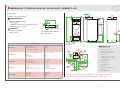
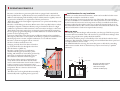
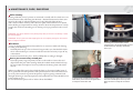
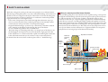
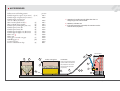
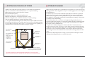
INSTALLATION AND OPERATION MAINTENANCE
• Biomatic+ 20 and 30
ARITERM SWEDEN AB
Installation, Operation & Maintenance - 2007.08.14- 1/24
CONTENTS
Important Information.....................................................................2
Dimensions / Items included / Technical Specification .......... 3-4
Operating Principle ..........................................................................5
Wiring Diagram................................................................................6
Control Panel ....................................................................................7
Installation Chimney ........................................................................7
Water Piping - Planning ..................................................................8
Filling of Water / Burner overview .................................................9
Maintenance, care, sweeping ....................................................10-11
Pellets Feed System ........................................................................12
Safety and Alarms...........................................................................13
Start-up in OFF mode ...................................................................14
Control Panel Layout - Default Settings .....................................15
Displayed Messages ..................................................................16-17
Troubleshooting ........................................................................18-19
Advice about Fuel Pellets ...............................................................20
Accessories .......................................................................................21
System Solution - Pellets Store .....................................................22
Storage Planning .............................................................................22
Installation Protocol.... ...................................................................23
IMPORTANT INFORMATION
• Keep this instruction manual readily available for future use.
• Read the instructions carefully before taking your pellets installation into service.
• The capacity of the burner is calculated according to the maximum volume of pellets that can be fed to and burnt in the burn pot during 1 hour (based on a normal,
average wood pellets quality as described in our fuel specification)
Follow
these instructions carefully and carry out care and maintenance work as
•
recommended.
Notification to building authority
Attention! When you change heating installation this must always be
communicated to the local building authorities.
Inspection
Heating installations installed after 01.01.1983 shall be inspected and approved by
an authorised inspector. The building authorities where you live can inform you about
this.
Sweeping
According to the fire protection laws a chimney shall be swept regularly. This is done
by the local chimneysweep. Sweeping of the boiler shall be carried out in such a
manner that good operating economy is achieved. (see under ”Maintenance”) Prepare
to chimney-sweeping by turning off the boiler at least one hour before cleaning to
minimize the amount of glowing ash.
Warning!
Make sure to cut the power supply to the boiler before removing the burner housing.
Maintenance contract
Ariterm recommends the boiler installation to be made by a company with professional competence. For more information please contact your Ariterm retailer.
Replacing of spare parts
Ariterm recommends that replacing of spare parts is made by authorized serviceman
of Ariterm retailer. The retailer supplies required spare parts and authorized serviceman makes the necessary adjustments and combustion gas analysis when replacing
spare parts.
Ariterm reserves the right to alter any details and specifications without prior notice.
ARITERM SWEDEN AB
Installation, Operation & Maintenance - 2007.08.14- 2/24
DIMENSIONS / ITEMS INCLUDED IN THE DELIVERY - BIOMATIC+ 20
Ø 102 outs.
Part Number
Biomatic+ 20 (part.no. 4010) *)
606
Standard delivery
180
440
A-dimensions including comb.flue
pipe is app. 1710 mm
425
677
11
12
342
261
1
TECHNICAL DATA
10
725
220
600
Dimensions are without
adjustable feet
8 - 20 kW
450 W
60 W
389
0,5 - 1,5 bar
max 120 o C
5-20 Pa
Connections
Expansion
Drain
Flue pipe connection
Recommended chimney diameter and
length
DN 25 male
DN 15 female
Ø 102 mm
Ø 100 mm, length min 5 m
Electrical data
Power supply
Supply cable
Fuse size
Power in operation
400 V 50 Hz
MMJ 4x2,5s
3x16 A
9000 W
49
Design pressure
Design temperature
Recommended draught
305
Design values
1.
2.
3.
4.
5.
4
9
62
606 x 945 x 1500 mm
245 kg
140 l
23 kg
100
Dimensions (width x depth x height)
Weight
Water contents
Weight (burner)
2
214
3
Dimensions
410
5b
758
Output using pellets
Power of ignition resistor
Normal power consumption
13
55
Performance
490
Comb.flue pipe
A=1460
Ø114
107
1500
Accessories
• Burner assembly kit
• Shunt outlet
213
Ø114
50
• Shunt valve ESBE TM 20
• Sweeping gear
• Combination flue for horizontal and vertical
installation (part no. 5206)
5a
8
130
157
6
7
Biomatic+ 20
Drain DN 15, inv.
Flue pipe Ø 139 mm
Additional shunt (optional)
Expansion DN 25, male
Shunt outlet
a) Feed line Cu 22 / DN 20
b) Return line Cu 22 / DN 20
6. Cold water Cu 22
7. Hot water Cu 22
8. Cabel bushing
9. Sweeping hatch
10. Ash box
11. Return line DN 25 female
12. Air valve
13. Ash compression
*) The simpler model of Biomatic+ 20, Biomatic+ 20 Ultra Light, is delivered
without electric heater, heat exchanger and internal circulation pump.
ARITERM SWEDEN AB
Installation, Operation & Maintenance - 2007.08.14- 3/24
DIMENSIONS / ITEMS INCLUDED IN THE DELIVERY - BIOMATIC+ 30
Ø 139 outs.
Part Number
Biomatic+ 30
195
606
(part.no. 4009)
53
1720
A=1700
Standard delivery
• Shunt valve ESBE TM 20
• Sweeping gear
• Combination flue for horizontal and vertical
installation (part no. 5208)
Accessories
• Shunt outlet
11
264
490
12
1
592
TECHNICAL DATA
389
3
DN 25 male
DN 15 female
Ø 139 mm
Ø 130 mm, length min 6 m
Electrical data
Power supply
Supply cable
Fuse size
Power in operation
400 V 50 Hz
MMJ 4x2,5s
3x16 A
9000 W
758
Connections
Expansion
Drain
Flue pipe connection
Recommended chimney diameter and
length
55
0,5 - 1,5 bar
max 120 o C
5-20 Pa
214
305
5b
5a
8
6
157
130
7
Comb.flue pipe
130
50
Design pressure
Design temperature
Recommended draught
49
Design values
100
606 x 970 x 1720 mm
330 kg
142 l
38 kg
598
255
4
9
Ø159
Dimensions
Dimensions (width x depth x height)
Weight
Water contents
Weight (burner)
156
128
12 - 30 kW
450 W
70 W
505
2
62
Performance
Output using pellets
Power of ignition resistor
Normal power consumption
54
10
13
Ø159
620
A-dimensions including comb.flue pipe
is app. 2000 mm
ARITERM SWEDEN AB
1.
2.
3.
4.
5.
Biomatic+ 30
Drain DN 15, inv.
Flue pipe Ø 139 mm
Additional shunt (optional)
Expansion DN 25, male
Shunt outlet
a) Feed line Cu 22 / DN 20
b) Return line Cu 22 / DN 20
6. Cold water Cu 22
7. Hot water Cu 22
8. Cabel bushing
9. Sweeping hatch
10. Ash box
11. Return line DN 25 female
12. Air valve
13. Ash compression
Installation, Operation & Maintenance - 2007.08.14- 4/24
OPERATING PRINCIPLE
Biomatic+ 20/30 the new generation pellet boiler is equipped with a 20/30 kW
built-in pellet burner. A pellet burner has many similarities with an oil burner. The
difference is that heating with solid fuel produces ash that must be regularly removed
to prevent loss of efficiency or impairment of burner performance.
The boiler is designed to meet highest requirements as to operational reliability, convenience, and safety.
Biomatic+ 20/30 belongs to the most efficient state-of-the art pellet boilers in today’s
marketplace. Optimal combustion efficiency and good insulation allows for a high
coefficient of performance while emissions to the environment are kept at a low level.
The boiler has automatic ignition but can always be ignited manually, if required. It
has two ignition programs depending on whether the burner is started from the OFF
position or from operating mode.
Operation of the boiler and its feed system are fully automated and are regulated in
three steps by the built-in control system. In the burn pot, pellets are mixed with air to
the ideal proportion to ensure complete combustion in a cost effective manner.
Biomatic+ 20/30 are equipped with an oversized
ash box to facilitate maintenance work.
Sweeping is mainly done from the soot-hatch on
top of the boiler but also through the rebox door
after the burner is pulled out.
Biomatic+ 20/30 consists of a combustion
chamber with flue pipes enclosed by a jacket
holding 140/142 litres of water. Heat generated by
the burner is transferred to the boiler water via
the combustion chamber and the flue pipes.
Heat for the radiator system is transferred via a
4-way shunt valve. In the shunt valve the boiler
water is mixed with return water from the radiators
so that a constant, correct temperature can be
maintained in the radiators in relation to the outdoor
temperature. This is a means to achieve better
heating economy.
The shunt valve can be regulated either manually or
automatically with a regulating device (optional).
Small dimensions for easy installation
Thanks to its modest dimensions Biomatic+ 20/30 can be installed in boiler rooms
that would normally be considered too small.
Most of the piping connections are placed on top of the boiler. The terminal block
for electric installation is accessible from the control panel. Service work is facilitated
by the fact that all connections and components are easily accessible from the front.
Sweeping takes place through the rebox door or through a cleaning hatch on top of
the boiler. Ashes collect in the oversized ash box that is attached to the ash door. The
ash box holds 50 litre of ash and is emptied when necessary.
Hot tap water
The efficient plate heat exchanger will ensure that you always get “fresh” hot tap water.
A strainer has been installed in the cold water line to prevent the heat exchanger from
becoming clogged (the water quality should be checked).
The internal circulation pump is controlled by a flow switch, fitted on the hot water
outlet pipe. The whole heat-exchanger package is located behind the electric panel and
is easily accessible for service work.
ATTENTION! Before servicing, disconnect the power to the boiler by switching
off the mains switches. Work on the boiler may only be carried out by a qualified
electrician.
cw
Strainer
hw
Flow switch
1
Front view of the heat exchanger
installation for hot tap water.
1. Plate heat exchanger
2. Internal circulation pump
2
ARITERM SWEDEN AB
Installation, Operation & Maintenance - 2007.08.14- 5/24
WIRING DIAGRAM
ARITERM SWEDEN AB
Installation, Operation & Maintenance - 2007.08.14- 6/24
CONTROL PANEL
1.
2.
3.
4.
5.
6.
7.
8.
9.
10.
11.
12.
13.
INSTALLATION
Fuse, circulation pump hot water circuit
Fuse, circulation pump external heating circuit
Switch, circulation pump hot water circuit
Switch, circulation pump external heating circuit
Overheating protection, burner. Reset button for high limit thermostat
Overheating protection, electric heating element. Reset button for overheating
cut-out
Control unit function keys. See chapter”Control Panel Layout”
Display panel for messages
Display of operating mode, alarm messages, system settings
On/Off switch. Main switch for pellet burner
Green indicating light. Is on when the burner is in operation mode
Red cause-indicating light. Is on when the burner is switched off or has stopped.
A message describing the cause is shown on the display panel
Flashing red/green cause-indicating light
Indication for programmed reminder alarm. Does not stop operation
Connection for external auger
1
2
8
5
6
77
1010-12
11 12
9
Chimney installation
To embed the angular tube in the chimney, proceed according to the drawing below.
If the tube is embedded as described, you will be able to avoid soot leakage when the
chimney is being swept. See page 3-4 about where to make the hole for the flue pipe
and the diameter of the hole.
Flue connection and combustion air intake
The combination flue of the boiler allows for connection towards the top as well as to
the rear. Boiler cement is suitable for sealing. Recommended flue gas requirements for
Biomatic+ 20/30: brick chimney lined with a Ø 100 mm (130 mm for 30) acid proof
thin-walled tube or an acid proof Ø 100 mm:s (130 mm for 30) element chimney.
Recommended underpressure for Biomatic+ 20 is 20 Pa (25 Pa for 30). The height of
the gas flue shall be dimensioned according to the building’s requirements, but should
be at least 5m for Biomatic+ 20 (6m for Biomatic+ 30). If condensation water comes
out of the flue, a condensate drain pan shall be installed in the lower portion of the
chimney. The combustion air intake must not be covered.
ATTENTION! The chimneysweep
must be notied for inspection of the flue.
44
3
The boiler shall be positioned and installed according to the building rules in force.
Before installing the boiler, the chimney must be controlled for underpressure and
possible risk of condensation. It is possible that an air draught compensator has to be
installed. Inner pipe is recommended for minimizing the risk of condensation.
Space needed for installation: Minimum clearance in front of the boiler (burner
included) is 1000 mm. Clearence on the top and at least by the other side of the boiler
shall be at least 0,5 m. The boiler must be level. If the floor is uneven, adjustments can
be made with the help of four adjusting bolts (enclosed with the boiler) that shall be
fitted to the bottom plate of the boiler.
The air intake duct to the boiler room must have at least the same area as the flues.
13
CAUTION! The boiler has low flue
gas temperatures, which, under certain
conditions,might lead to condensation of
flue gases.
30
Mortar
Flue pipe
30 mm incombustible
insulation
ARITERM SWEDEN AB
Installation, Operation & Maintenance - 2007.08.14- 7/24
WATER PIPING
Water piping shall be carried out in accordance with current local and national hot
water and building regulations. Safety equipment shall be installed in accordance with
regulations in force.
If a closed expansion vessel is used, an approved safety valve, a pressure gauge, and a
vent valve shall be fitted. The safety valve shall be fitted just above, but not directly on,
the boiler in such a manner that the connection with the boiler cannot be closed off.
The connecting line from the boiler to the safety valve must rise continuously. Before the
boiler is filled with water, the enclosed drain tap shall be fitted.
Radiator system and expansion vessel
When you fill the system, all valves must be open and the external circulation pump
turned off. Bleed the system carefully while filling. When the installation has been in
service for a few days, it shall be bled and refilled once again.
ATTENTION! See also separate instructions for filling of water.
The volume of the expansion vessel is determined as follows:
Open system:
5% of the water volume in the heating system.
Closed system:
Select the volume of the vessel in accordance with the manufacturer’s instructions.
In the following table, you will find examples of suitable closed system expansion
vessels.
System volume
(litre)*
Opening pressure
(bar)
Initial pressure
(bar)
500
1000
1500
2000
1,5
1,5
1,5
1,5
0,5
0,5
0,5
0,5
Vessel volume
(litre)
70˚C 90˚C
35
80
80 140
80 140
140 200
Planning and installation
Planning and installation shall be carried out in a professional manner, attention being
paid to general and local rules and regulations. Operating pressure is max.
1,5 bar. Before taking the installation into service, and always at the beginning of the
heating season, the following checks shall be carried out:
• that the heating system is filled and bled
• that the circulation pump is working
• that the system valves are open
• that the automatic control and safety devices are in working order
• that the chimney has the necessary draught and that the fresh air ventilation
is open.
Safety valve
If a closed expansion vessel has been installed in the radiator system, the safety valve
must be checked 4 times a year.
Activate the valve by pressing or turning the control button and check that water escapes from the overflow pipe connecting the valve to the drain.
Elecktrical installation
The supply cable delivered with burner is connected to the burner. In addition, an
over-temperature protection thermostat must be installed in the boiler (this must
acquired separately). The connection is made in accordance with the wiring diagram
annexed to this manual. Also the use of a safety switch (burner switch) is recommended. The other connection cable delivered with the burner is for boiler temperature
and flue gas sensors. Work on the burner may only be carried out by a qualified serviceman. Make sure to cut the power supply to the burner before servicing.
An open system with 500 litre water volume demands at least a 35 litre expansion vessel and a 1500 litre
system volume a 80 litre expansion vessel
* System volume = boiler volume + storage tanks + piping volume + radiator volume.
ARITERM SWEDEN AB
Installation, Operation & Maintenance - 2007.08.14- 8/24
FILLING OF WATER
Before you begin heating, the heating system must be filled with water.
To fill the system, do as follows:
1 Open all shut-o valves, including the shunt valve.
The pump must be switched off.
2 Fill the boiler and the radiator system with water.
Bleed the system at the radiators.
3 Once the system is filled completely, the circulation pump can be started and
heating can begin.
4 When the boiler water has reached its pre-set operating temperature, the pump
should be stopped and the system bled at the radiators once again. This should be
repeated several times.
Remember that much air is enclosed in tap water. The enclosed air volume may reach
as much as 10%, which explains why bleeding takes time – especially where there are
large water volumes.
A closed system shall be filled until the pressure gauge indicates the correct system
pressure, i.e. the distance from the pressure gauge to the highest radiator in meter
times 0,1 which gives the system pressure in bar.
Adjust the red needle of the pressure gauge to the same value as the big needle.
Heating with electric heating element
Ariterm Biomatic+ 20 and Biomatic+ 30 has been fitted with a factory wired 3-phase
6/9 kW electric heating element.
The power of electric heating elements can be adjusted in service menu.
BURNER OVERVIEW
5
4
6
10
2
1
12
11
7
1.
2.
3.
4.
5.
6.
Primary ring
Primary air tube
Optical monitor tube
Level monitor, receiver
Top coupling
Level monitor, transmitter
3
7.
8.
9.
10.
11.
12.
ARITERM SWEDEN AB
8
9
Fan
Auger tube
Burn pot
Sluice gate
Auger motor (at the rear)
Chain
Installation, Operation & Maintenance - 2007.08.14- 9/24
MAINTENANCE, CARE, SWEEPING
Boiler cleaning
Burning solid fuels, even if operation is automated, normally calls for a little more care
and maintenance than oil heating. For Biomatic+ 20/30 maintenance has been minimized as the result of well planned design and a big ash box holding 50 litres.
Ash is removed when necessary. The convection parts of the boiler are to be cleaned
when the flue gas temperature has risen by 20-30˚C above the temperature of a newly
swept boiler. An alarm reminding you of cleaning can be programmed on the control
panel.
ATTENTION! Pay special attention to the pellets quality when you receive a new delivery or when
you change supplier.
ATTENTION! Show a great care when emptying the ash as it might be glowing hot. Ash must be
kept in a fireproof container.
The burner
- Carry out checks and measures when needed or in connection with boiler cleaning
according to the following:
• Normally, the burn pot does not demand any particular care, but should be checked for carbon build-up in connection with ash removal. If necessary scrape off any
carbonisation.
• Put the burner back into place - check carefully that no sealing is damaged.
1. Switch off the burner one hour before cleaning.
2. Cleaning the convectional flues. Lift the
sweeping hatch at the top of the boiler and clean
the flues with brush. Cleaning is needed few
times a year.
3. Cleaning brush is included in Ariterm pellet
boiler delivery. Move the brush through the flues
to sweep the ash from flue walls.
4. Optional cleaning device makes the cleaning
even easier. Pull the adjuster at the top of the
boiler a few times to sweep the ash from the
flues.
Once a year to once every second year
• Clean the primary ring and primary air tube on the inside to remove dust and
chips. Check the pins of the metering wheel, the toothed wheel and the back stop
for wear. Adjust and replace if necessary. Lubricate the driving chain with a little
thin oil.
When new pellet fuel is used, always check the burn pot for sintered ashes (crust of
ash or gravel and stone-like particles). Such particles must be removed from the burn
pot at very short intervals to prevent the primary ring from getting overheated and
damaged. Sintering is caused by impurities in the pellet fuel and a claim should be sent
to the supplier at once.
For more information please refer to ”Advice about Fuel Pellets”.
ARITERM SWEDEN AB
Installation, Operation & Maintenance - 2007.08.14- 10/24
MAINTENANCE, CARE, SWEEPING
5. Cleaning the burner. Remove the fixing bolts
from the burner and loosen the hose and electric
connections. Pull out the burner.
6. Remove the ash by brushing the walls of the
combustion chamber. Clean the burn pot and
the air cracks.
7. Emptying the ash. Pull out the ash box. Empty
the ash into a decked fireproof container outdoors. Because of the fire risk, the container must
not include anything but ash.
8. Ash compression lengthens the interval between emptying the ash. The ash tightens when
the adjuster is moved back and forth.
9. Emptying the ash is even easier with an ash
cyclone, which works like a vacuum cleaner. It is
important not to vacuum hot ash because of the
fire risk.
10. Ash screw carries the ash from ash box to
a larger, wheeled carriage, which is easier to
empty. (Extra equipment)
11. Remaining ash which is collected in a fireproof container…
12. … can be used as a fertilizer.
ARITERM SWEDEN AB
Installation, Operation & Maintenance - 2007.08.14- 11/24
PELLETS FEED SYSTEM
• Pellets are feed automatically from the external pellet store to the burner via a specially designed feeding system, adjusted to the individual installation and regulated
by the burner control unit. It is based on the safety principle of interrupted fuel
flow by free fall (gravity feed chamber) between the external pellets feed and the
burner.
• The burner auger motor and the external auger motor are equipped with an overheating safety switch as a protection against overheating.
ATTENTION!
To eliminate the risk of the connecting hose becoming overfilled with pellets, the
boiler should not be combined with any other external feeding system.
3
4
7
1
1. Bulk refill connection
2. Feeding hose to burner
3. Augerpipe, outlet unit
4. Motor
5
3
4
2
2
5. Auger tube with inserted flexible auger for 8mm pellets
6. Augerpipe, inlet unit
7. Vent tube Ø=200mm
5
7
1
6
6
ARITERM SWEDEN AB
Installation, Operation & Maintenance - 2007.08.14- 12/24
SAFETY AND ALARMS
The boiler is designed according to the same main principles as an oil heated system.
The advantage of this pelletsystem is easy and comfortable handling, as the location of
the fuel store does not depend on the layout of the boiler room. From the safety point
of view, the separation of fuel store and burner in combination with interrupted fuel
supply between the two means high security.
• In the event of temperature sensor failure, the high-limit thermostat stops operation to prevent the boiler from overheating. The burner automatically resumes
normal operation after power failure or interrupted fuel supply.
• Equipment failure leading to operation stop is indicated by a red LED combined
with a message on the display panel indicating the cause of the failure.
In case of fuel shortage, there is also an audible alarm.
• The boiler design is outstanding with safety as an integral part of the function. As
the fuel supply is interrupted and corrected in the burner auger pipe before the
boiler wall, there is no continuous fuel line capable of transferring heat outside the
boiler wall which means that you do not have to rely on extra safety devices.
For details about the various alarm conditions please refer to ”Troubleshooting”.
Safety is a natural part of the burner function
Each time filling takes place, only a limited amount of pellets (150 g) is transported
through the external feeding system from the storage bin to the top feed connection.
To make sure that the correct amount of pellets is supplied from the top feed
connection to the burn pot, a separate supply auger has been installed immediately
under the top connection controlling the supply of pellets through the air lock and
burner auger. As the burner auger is feeding pellets to the burn pot three times a fast
as they are supplied, a safety zone containing only a few seperated pellets is created
between the air lock and the burn pot. This safety zone is always kept intact even in
case of power failure, insucient maintenance or equipment failure. In consequence,
safety has become an integral part of the burner functionality.
Top feed connection
Back flow
preventer
plate
Supply
control
auger
Air lock
Primary air tube
Ignitor tube
Burner auger
Fan
Boiler front
ARITERM SWEDEN AB
Installation, Operation & Maintenance - 2007.08.14- 13/24
START-UP IN OFF MODE
Start-up in OFF mode (cold burner start with electrical ignition)
You can only start up in this way when the burner has been switched off at the control
panel or when the power is restored after a power cut. The boiler temperature must be
8 degrees below its set-point value.
Attention! When the boiler is started for the first time after installation this must be
done by an authorised installer.
• If the external feed system has been emptied of pellets, it must be refilled before
you can start. The easiest way to refill the system is to remove the filling hose from
the burner top coupling letting it hang freely over a container. Switch on the power
to the burner control unit so that the operation indicating light is red. Operating
mode shall be OFF. Scroll through menu 1 with the arrow-forward key until you
reach EXTERNAL AUGER MANUAL and time (15 min). Start the external
auger by pressing the plus-key. Remaining operating time is indicated on the
display panel. The external auger can be stopped with the minus-key before the
programmed time has elapsed.
• To start the burner, scroll through menu 1 with the arrow-forward key until you
reach ON/OFF. Select ON with the pluskey. This starts the motor of the burner auger feeding fuel to the burn pot. After another 3 min the fan and ignition
element will become activated. When the fuel level has reached about the height
of the ignition element’s hot air outlet, the feeding rate will be reduced and after a
total of some 6-7 minutes the pellet fuel will ignite.
Start and stop in operating mode
The green LED indicates that the burner is in operating mode.
During operation, start and stop is regulated by the boiler temperature sensor. When
the water temperature falls to 5 degrees below its set-point value, the burner starts in
the programmed low power mode. If the water temperature falls by an additional 2
degrees to 7 degrees below the set-point value, the programmed high power mode is
activated. The burner will then operate in this mode until the temperature has risen to
4 degrees below set-point value when it returns to low power mode. When the burner
is working, the green LED is lit.
A red light indicates that the burner is not in operation (see ”Troubleshooting” )
OFF
To switch o the burner open menu 1 and go to ON/OFF using the arrow-forward
key. Select OFF using the minus key.
When the burner is switched OFF, a red light is lit on the control panel to indicate
that power is connected.
Attention! Always switch off the power to the burner during service work.
• The boiler ’s optical monitor detects when the fuel has ignited and switches off the
ignition element. The red light goes out and the green comes on to confirm that
the burner is operating. Fan speed is reduced. At the same time the fuel feed motor
stops for three minutes to allow all the pellets in the burn pot to ignite. After that
pellets will be fed at reduced speed for another 5 minutes. After a subsequent wait
time of 10 minutes, the burner control cuts in and controls the operation of the
burner. If ignition fails, this is indicated by red light and an alarm message on the
display panel.
Attention! Sometimes, when the burner is started for the first time, or if there are
no pellets in the burner, a fire-start might be necessary after some 3 minutes operation. It is always possible to light the fuel manually using fire-lighting fluid.
ARITERM SWEDEN AB
Installation, Operation & Maintenance - 2007.08.14- 14/24
CONTROL PANEL LAYOUT
Control Computer and Menus
1
2
1. Display for set values
2. Display of operation and active alarms with indi
cation light
Green: Burner in operation
Red: Alarm (burner not in operation)
Flashing: Warning light (does not switch off the
burner)
Browsing forward in the menu
Browsing backward in the menu
Increases the set values
Decreases the set values
Default Settings
The settings made at the factory cover most of the control system functions.Normally
only the following adjustments have to be made.:
1 Selection of operating mode (heat source)
2 Adjustment of set-point value for boiler temperature (desired temperature
of boiler water).
3 Programming of desired value for reminder alarm.
Service Levels
The control unit has dierent menu levels for the adjustment and viewing of the control
system parameters. The tables on page 14-16 will give you a detailed description of the
menus shown on the control unit display panel. Normally the control unit is at menu
level 1.
To reach menu level 2 ”Service”, do the following:
• Press arrow forward and arrow backward at the same time for 5 seconds.
The message ”Service” is shown on the display panel.
The control unit is now at the service menu.
• Move forward in the service menu by pressing ”arrow forward” .
If you do not press any of the control keys, the control unit will revert to menu 1
automatically after 8 minutes.
There are two more service levels, but they are reserved for the service
technician only.
On (-Off)
Service
Reaching the menu
level ”Service”
ARITERM SWEDEN AB
Installation, Operation & Maintenance - 2007.08.14- 15/24
DISPLAY MESSAGES AND POSSIBLE ADJUSTMENTS
The following tables give an overview of the messages, which may appear on the
display of the control unit. They also indicate which parameters the user is allowed to
change, and which parameters are allowed to be changed only in case that the user has
been given instructions from an authorised installer. Note that a part of the menu options are displayed only when they are activated.
Description of level 1 menu ->
Text on the display
Description
Setting possibilities
Temperature boiler xx
(80) °C
Boiler temperature, set value in brackets. Shows the
actual temperature of the boiler, the set value shows
the desired temperature.
Adjustable between 20 and 95°C by
means of the Plus and Minus buttons.
ON (OFF)
Operating mode. In ON mode the burner switches on
when needed. In OFF mode the next menu displays
“Auger external manual”.
Selectable by means of the Plus and
Minus buttons.
Operation mode, pellet
(The menu is displayed
only when the electric resistors are activated)
Options:
• pellet
• electric (the function electric resistors is enabled
only in Biomatic+ models).
Selectable by means of the Plus and
Minus buttons.
Operation mode
OFF, start, stop, temperature hold, max, medium,
min, electric. This menu also displays the different
starting stages.
For information only.
Temperature flue gas
Flue gas temperature
For information only.
Operating time press
plus key
Press the Plus button and then the arrow button
“forward” to the next screen, if you want to view
the operating time data.
The operating time is reset by pressing
the Plus and Minus buttons simultaneously for 3 seconds.
Operating time total
Total operating time of the burner.
Operating time high
Operating time at high power.
Operating time low
Operating time at medium power.
Operating time min
Minimum power level during operating time (only
displayed when the min operating level is activated)
Operating time electric el1
Operating time of the resistor 1
The number of electric resistors vary between models. (Biomatic+ function)
Operating time electric el2
Operating time of the resistor 2
(Biomatic+ function)
Pellets store press plus key
Press the Plus button and then the arrow button
“forward” to the next screen, if you want to view
the pellets store data.
Estimated time left
Displays the number of operating days at the average consumption level in question.
Text on the display
Description
Setting possibilities
Pellets store
Displays the amount of pellets in the store, a new
figure can be entered in connection with reloading
the pellets store.
For information and can be changed.
Feeding factor
Displays the feeding power of the external auger
Adjustable between 0 and 76.7 kg, see
“Determination of the feeding factor”.
Consumption average
Displays the average consumption during the last
8 days.
For information only.
Consumption total
Displays the total consumption of pellets.
For information only.
Auger external total
Displays the total operating time of the external auger in hours
For information only.
Alarm pellets min
Sounds an alarm for calculated set minimum amount
of pellets in the store.
Adjustable between 0 and 3.0 tons.
Service press plus key
Press the Plus button and then the arrow button
“right” to the next screen, if you want to view the
service menu.
Alarm ash removal
Sounds an alarm for emptying the ash box upon
reaching a set value.
Adjustable between 0 and 250 h, according to the operating time of the
external auger.
Alarm cleaning
Sounds an alarm for cleaning of the combustion
head upon reaching a set value.
Adjustable between 0 and 250 h, according to the operating time of the
external auger.
Alarm audible
Audible alarm sound for a pellet shortage can be
activated.
Adjustable “yes/no”
Flue gas max °C
Audible alarm for cleaning of the convection parts
upon reaching a set value
Adjustable for alarm “max value” between 120 and 280°C
For information only.
ARITERM SWEDEN AB
Installation, Operation & Maintenance - 2007.08.14- 16/24
DISPLAY MESSAGES AND POSSIBLE ADJUSTMENTS
Description of menu 2 – Service
Service: To select this menu press both arrow buttons simultaneously for. approx. 5 seconds, then press the arrow button forward
to the next screen.
Text on the
display
Description
On (Off )
Service
Setting possibilities
El Step
Displays in brackets the activation of one of the electric resistors
(enabled only in Biomatic+ models).
To activate one of the electric resistors enter number (3) here by means of the Plus
button.
Start backup heat
15°C
Displays temperature difference from the target temperature, at which the electric resistor is switched on
(enabled only in Biomatic+ models).
Adjustable between 10 and 40°C.
Level monitor
Measured light intensity in percentage.
The set limit value for the light in brackets in percentage.
Adjustable between 10 and 90%.
Measured light intensity in percentage.
The set limit value for the light in brackets in percentage.
Adjustable between 1 and 98%.
Optical monitor
level
Testing press plus
key
Description of menu 3 – Power
Power: In order to activate this menu, select number 5 in the “Service” - “Power” menu by pressing the Plus button. Wait, until the number stops flashing and continue by pressing the arrow button to the right.
Text on the
display
Power
Burner type *)
Press the Plus button and then the arrow button to the
right, if you want to view the test values.
Description
Setting possibilities
The menu is activated by entering code 5. Wait,
until the number stops flashing and continue by
pressing the arrow button to the right.
0
12-30 kW *) Note: Don’t change the factory
setting, button -> resets the original settings.
12, 20 and 30 kW
Power high auger
Setting of fuel feed to high power (%).
50 to 100%, adjusted by means of the Plus/Minus buttons.
Note! The maximum value is 90% for 20 kW.
Power high fan
Setting of speed of the fan to high power (%).
1 to 100%, adjusted by means of the Plus/Minus buttons.
Power low auger
Setting of fuel feed to medium power (%).
35 to 70%, not in use at level 0.
Power low fan
Setting of speed of the fan to medium power
(%).
1 to 100%, adjusted by means of the Plus/Minus buttons
Power min auger
Setting of fuel feed to low power (%).
20 to 50%, not in use at level 0.
Power min fan
Setting of speed of the fan to low power (%).
1 to 100%, adjusted by means of the Plus/Minus buttons.
Cleaning fan
Frequency of cleaning blows
0 to 4 blows/h.
Holding time
Time between maintenance periods for the glow
of embers
20 to 120 minutes, in increments of five minutes,
adjusted by means of the Plus/Minus buttons.
Auger external
0/1 manual test.
Enabled by pressing the Plus button, disabled by pressing the Minus button.
Fan
0 to 100%
Enabled by pressing the Plus button.
Auger burner
0/1 manual test.
Enabled by pressing the Plus button.
Ignition
0/1 manual test.
Enabled by pressing the Plus button. Note:
the test is performed only when the fan is
running.
Alarm
0/1 manual test of the alarm diode.
Enabled by pressing the Plus button.
El Step
0/1 manual test (enabled only in Biomatic+ models).
Enabled by pressing the Plus button.
Power regulation
0
See the next menu.
Auger external time
Setting of operating time for the external auger.
1 to 250 seconds.
English
Selection of the display language.
Finnish, Swedish, English, German or Italian
can be selected by pressing the Plus/Minus buttons.
Auger external manual
Setting of operating time for the external auger in
manual operation, see page 13.
3 to 60 minutes, adjusted by means of the Plus /
Minus buttons.
Address
0
Not used.
Hot starts
Displays the number of hot starts.
Is reset by pressing the Plus/Minus buttons simultaneously for 3 seconds.
Default set vXXXX
Displays the version number of the processor and enables resetting the factory settings.
The factory settings can reset by pressing
the Plus button.
Cold starts
Displays the number of cold starts.
Is reset by pressing the Plus/Minus buttons simultaneously for 3 seconds.
ARITERM SWEDEN AB
Installation, Operation & Maintenance - 2007.08.14- 17/24
TROUBLESHOOTING
In case an alarm becomes active, this is indicated on the display of the control panel
with a red light and a text message. This facilitates troubleshooting, because the user
can see the cause of the problem. The alarm is acknowledged by selecting OFF on the
control unit. The cause of the alarm must always be determined and the problem removed before the device is switched on again.
Problem
The following checks and remedies are described in such an order that the most probable cause of the problem is given first.
Problem
All display segments are out.
The red operation indication is on.
The display reads: ALARM PELLETS NO.
The burner is requesting fuel, but
has not received it.
Check
Remedy
that the fuses of the control unit of the
burner are intact and the main switch
has been turned ON.
has the over-temperature protection
tripped?
Replace the defective fuse in the control unit or turn ON the power by means of the main switch. Note! Disconnect the device from electricity supply
before replacing the fuse. The size of
fuses F1 and F2 is 4A/230 V.
If the cause of over-heating cannot be
determined with certainty, contact an
authorised technician. If the over-temperature protection of the boiler has
tripped, put it back into operation by
pressing the RESET button. After this
switch the control unit OFF and then
back ON. Also check that the 3-phase
current is correctly connected.
that there are pellets in the fuel storage.
Add pellets.
that the inclination of the drop pipe is
not too gentle.
Shake the drop tube and change the
inclination so that pellets will not get
stuck.
The red operation indication is
on and the display reads: ALARM
MAX THERMOSTAT, or
ALARM MAX THERMOSTAT ELECTRIC
The over-temperature protection of
the boiler has tripped.
The red operation indication is on
and the display reads:
CONTROL EL. IGNITION or
CONTROL OPTICAL MONITOR
The cause of the problem is that
the optical flame monitoring of
the burner has not detected flame
during a certain period of time. No
fuel has entered into the combustion head.
Check
Remedy
that the motor shaft rotates the auger
and the motor of the external auger
operates.
(In most cases the default setting of the
operating time of the external auger (30
seconds) is not long enough to bring sufficient amount of pellets to the burner. If
the problem cannot be removed by means of the above checks and remedies,
the operating time of the external auger
may be too short. In such cases increase
the operating time (see page 15, menu 3
-> ”Auger external time”). However, the
operating time must not be so long that
pellets accumulate into the drop tube.)
If the motor does not rotate, disconnect
the power cable from the boiler and
connect it directly to a mains socket by
means of the additional cable provided.
If the motor has been over-heated due
to a blockage or for some other
reason, the over-temperature protection of the motor may have been tripped. The motor will not start until it has
been cooled down. Also check that there are no blockages in the auger.
If there are problems with the motor,
contact an authorised technician.
has the over-temperature protection
tripped?
check the circulation pump.
If the cause of over-heating cannot be
determined with certainty, contact an
authorised technician. If the over-temperature protection of the boiler has
tripped, put it back into operation by
pressing the RESET button. After this
switch the control unit OFF and then
back ON. Also check that the 3-phase
current is correctly connected.
that the flame guard and/or the combustion head is not full of ash and
the flame guard has not over-heated
or sooty.
Remove ash, clean the combustion
head from loose ash and wipe the
flame guard clean. If the flame guard
becomes easily sooty, the cause may
be incorrect settings or too low underpressure in the furnace. In such cases
call a technician.
ARITERM SWEDEN AB
Installation, Operation & Maintenance - 2007.08.14- 18/24
TROUBLESHOOTING
Problem
Check
The device has been stopped during a
hot start.
Remedy
The red operation indication is on
and the display reads:
ALARM LEVEL MONITOR, or
ALARM BLOCKAGE
The cause of the problem is that
the optical flame monitor of the
burner has not detected light during a certain period of time. No
fuel has entered into the combustion head.
is there fuel in the upper connection?
Check
Remedy
Check that the pellets fed into the
combustion head are whole. The fuel
consists of pieces, the burner cannot
keep up the embers. The reason for recurring stops may also be an excessive
play in the blocking feeder, which makes it difficult to keep up the embers.
Check the function of the ignition resistor, unless ignition does not succeed
after two start attempts.
The device has been stopped during
a cold start.
Problem
If the cause of the operation cannot
be determined with certainty or the ignition resistor must be replaced, contact an authorised technician.
that the feed auger, blocking feeder
and burner auger rotate and are not
blocked, e.g. because of a foreign
object.
If there is no fuel in the upper connection of the burner, check the cable
connections of the level switches. If
this does not help, wipe the level switches clean. If the external feed of the
burner does not start in spite of this
or the level switches must be cleaned
continuously, they may be defective
and, when necessary, should be replaced by an authorised technician.
ARITERM SWEDEN AB
The dosing wheel and the toothed
wheel may hit each other and get
stuck, if they are close to each other.
The toothed wheel can be worn or the
device preventing backward rotation
may be in wrong position.
Remedy the possible problem. Remember to put the device preventing
backward rotation back in place after
the burner has been turned. A possible
foreign object in the pellet fuel must
be removed, if it gets stuck in the
blocking feeder or in one of the feed
augers. Remove the upper connection and take out the possible foreign
object from the feed auger or blocking
feeder. In connection with the inspection of the burner auger remove the
four augers located between the inner
and middle part and pull out the burner auger from the tube. Be sure to
disconnect all cable connections.
Installation, Operation & Maintenance - 2007.08.14- 19/24
ADVICE ABOUT FUEL PELLETS
• Pellet fuel can be manufactured from several different biologically derived raw
materials. Most common is wood, but today there are several alternative materials
available on the market that are suitable for pellets manufacture.
These raw materials have various characteristics that can be advantageous or disadvantageous for pelletised fuel.
Important factors that can be assessed are energy content, size, amount of fines,
moisture content and, last but not least, the price. We recommend that you choose
the fuel that has the lowest cost per energy unit after checking how the fuel performs in the burner. Study carefully the fuel performance after new delivery.
In case of doubt, please contact us at Ariterm.
• Most of the problems that arise on account of inferior fuel quality are the result of
inadequate handling and storage before the fuel reaches the end customer.
If the fuel has high fines content the problem is usually due to separation
during storage or loading.
The formation of sintered ash is due to silicate contaminants (sand). Theses
cannot be discovered before they are used. If you get pellets that produce
sintered ash, a claim must immediately be sent to the pellet supplier.
ATTENTION! If sintered ash is formed, the burn pot must be continuously
cleaned of sintered material (with a table spoon for example).
• Damp pellets can be the result of inadequate handling and transport.
If possible, inspect the pellets before they are unloaded to make sure that
you get clean and dry pellets and no fines.
ATTENTION! Damp pellets must be rejected immediately.
FUEL RECOMMENDATION
Raw material
Chemically untreated barkless wood
Diameter
8 mm
Length
15 to 32 mm
Volume weight
over 600 kg/m3
Moisture content
less than 10 %
Ash content
less than 0.7 weight %
Fine material content
max 4 weight %
Melting temperature of ash
> 1100 °C
Energy content
>4,75 kWh/kg
ARITERM SWEDEN AB
Installation, Operation & Maintenance - 2007.08.14- 20/24
ACCESSORIES
Pellets store and feeding system
Flexible auger kit, option 1 (no motor) (3+9)
Flexible auger compl. 2,0 m (no motor)
Flexible auger compl. 3,0 m
incl. 45˚ elbow (no motor)
Motor 45 W (small model) 1)
(4)
Motor 120 W (large model)
(4)
Flexible spiral, cut lengths (min 1 m)
(8)
Flexible spiral, 12 m, kit
(8)
Flexible spiral, 24 m, kit
(8)
Flexible pipe straight, 3 m, Ø 75 mm
(5)
Flexible pipe straight, 6 m, Ø 75 mm
(5)
Elbow 45˚ 2)
(6)
Elbow 90˚ 2)
Store pipe 3 m with core pipe
(7)
Bulkfilling pipe 3)
(10)
Connecting pipe
Hose 1 m incl. 2 hose clips
(2)
part.no
2413
2426
1) Attention! The small motor only allows less than 3 m
straight auger tube and one intake.
2) Minimum radius 800 mm.
3) If the refill connection is extended, the extension must be
made of metal (no plastic)
2425
2415
2416
2434
2435
2436
2427
5447
2428
2442
2443
2444
2433
0011
Pellets Boiler
4
3
11
10 *)
10
11
9
Pellets storage bin
ATTENTION !
max 3 piece feeding holes
*) If the refill connection is
extended, the extension
must be made of metal
(no plastic)
7
6
2
1
5 8
12
ARITERM SWEDEN AB
Installation, Operation & Maintenance - 2007.08.14- 21/24
SYSTEM SOLUTION PELLET STORE
STORAGE PLANNING
Thanks to the pellet feed system the pellet store can be built for bulk deliveries.
The store can either be located inside the house or in a separate building.
Pellets must, however, never be exposed to moisture.
Data for exible feed system:
Maximum climb: 2,5 m / Maximum gradient: 45˚
Minimal radie: 800 mm / Outside pipe diameter: 75 mm
Attention! The pellet store can have a maximum of 3 intake openings.
The store shall be well sealed to avoid the spreading of dust.
• As a guide when determining the size of the store, it may be useful to know that
the minimum bulk delivery is normally 3 tons if you wish to avoid freight surcharge.
1 ton of pellets corresponds to about 1,6 m3. To accommodate 3 tons of pellets you
would need a store of at least 6 m3 to have some space to spare.
Bulk filling pipe
Ø 100 mm
Vent pipe Ø 200 mm
Attention!
If filter sack is used
for filling we
recommend
2 x Ø 200 mm
Inspection hatch
600 x 600 mm
Stud 45x95 mm
c/c 600 mm
Slippery plywood
board 16 mm
Horizontal stud
45x95 mm
50˚
2 x horizontal
studs 45x95 mm
Vertical studs
95x45 mm
c/c 600 mm
When planning the pellet store you should keep in mind that you cannot use the same
feeding system for a store designed for a day’s or a week’s supply as for a store designed
for bulk deliveries.
A common way is to start with a small and simple pellet store which is a quick and
simple solution. It demands a bit of handling however, both when you pick up the
pellets from your supplier and when you fill them into your store. For this kind of
store, pellets can be acquired in small sacks (normally between 6-20 kg) or large sacks
(normally between 500-1000 kg).
The very best solution for a convenient and simple handling of pellets however is
to install a pellet store designed to accommodate pellets delivered by bulk tanker. This
delivery method will demand a store of some 6 m3 to accommodate 3 tons which is
the normal volume at bulk deliveries.
The pellet store should be designed to eliminate the risk of contamination and
moisture penetration. Take special care to avoid damp penetration through the walls
and floor. It is also important that pellets are not exposed to direct contact with water
in the form of rain or condensation. Pellets do not however absorb moisture from
surrounding moist air and can therefore be stored outdoors as long as they are under
cover.
The fuel store should be planned according to your estimated consumption so that
refilling and handling takes place at convenient intervals.
80 mm
Store pipe (delivered by Ariterm),
see previous page. The whole length
of the store pipe shall be supported.
The drawing represents a stand alone pellet storage bin. If the store is built
against a supporting wall, the sloping studs will have to be arranged differently.
ARITERM SWEDEN AB
Installation, Operation & Maintenance - 2007.08.14- 22/24
INSTALLATION PROTOCOL
After installation the burner has to be adjusted. To test every power range, press plus key for 8 seconds in On/Off menu, then can high, low and min modes be tested
manually. Returning to normal position: Press minus key once.
Flue gas temp. High
CO
O2
CO2
Efficiency
Draught (mm)
Fan
Effect %
Flue gas temp. Low
CO
O2
CO2
Efficiency
Draught (mm)
Fan
Effect %
Flue gas temp. Min
CO
O2
CO2
Efficiency
Draught (mm)
Fan
Effect %
Air-fuel ratio
Air-fuel ratio
Air-fuel ratio
INSTALLER
Retailer / Installer
Installed by
Inst. date
If these instructions are not followed during installation, operation and maintenance,
the obligations of Ariterm AB under the warranty regulations are no longer binding.
Ariterm reserves the right to alter any details and specifications without prior notice.
ARITERM SWEDEN AB
Installation, Operation & Maintenance - 2007.08.14- 23/24
ARITERM SWEDEN AB
Installation, Operation & Maintenance - 2007.08.14- 24/24
Ariterm Sweden AB | Flottilvägen 15 39241 Kalmar Sweden
www.ariterm.se | +46 480 442850