1
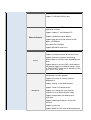
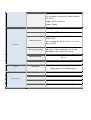
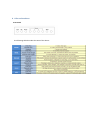
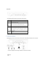
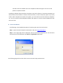
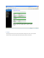
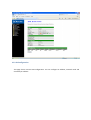
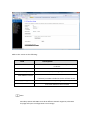
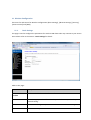
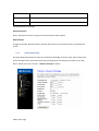
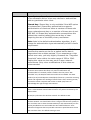
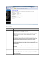
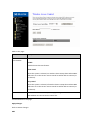
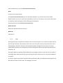
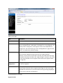
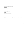
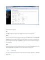
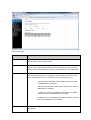
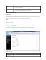
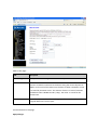
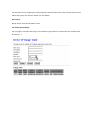
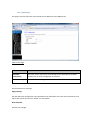
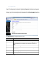
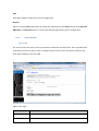
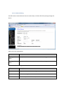
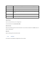
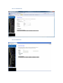
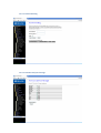
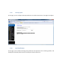
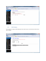
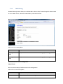
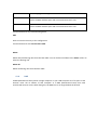
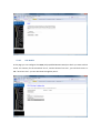
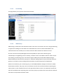
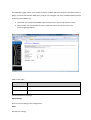
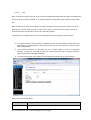
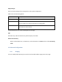
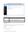
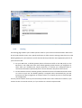
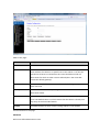
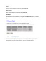
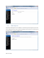
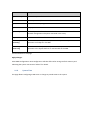
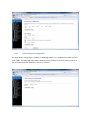
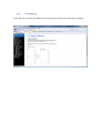
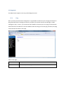
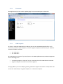
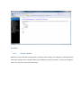
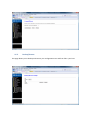
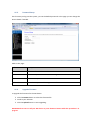
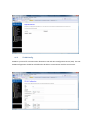
RTA04W
ADSL2+ 11b/g HOME GATEWAY
User Manual
CONTENT TABLE
1.
INTRODUCTION ................................................................................................................. 4
2.
APPLICATION .................................................................................................................... 4
3.
TECHNICAL SPECIFICATIONS AND FEATURES .............................................................................. 5
4.
PACKING LIST ................................................................................................................... 8
5.
SAFETY PRECAUTIONS ......................................................................................................... 8
6.
LEDS AND INTERFACES ........................................................................................................ 9
7.
HARDWARE INSTALLATION................................................................................................. 10
8.
ACCESS THE ROUTER ........................................................................................................ 11
9.
STATUS ......................................................................................................................... 12
10.
LAN CONFIGURATION ...................................................................................................... 13
11.
WIRELESS CONFIGURATION ................................................................................................ 15
11.1.
BASIC SETTINGS .................................................................................................................... 15
11.2.
ADVANCED SETTINGS ............................................................................................................. 16
11.3.
SECURITY ............................................................................................................................. 18
11.4.
ACCESS CONTROL .................................................................................................................. 20
11.5.
WPS ................................................................................................................................... 22
12.
WAN CONFIGURATION..................................................................................................... 24
12.1.
CHANNEL CONFIGURATION ..................................................................................................... 24
12.2.
ATM SETTING ...................................................................................................................... 25
12.3.
ADSL SETTING...................................................................................................................... 27
13.
SERVICES ....................................................................................................................... 28
13.1.
DHCP CONFIG...................................................................................................................... 28
13.1.1.
13.2.
DHCP Mode .............................................................................................................. 28
DNS ................................................................................................................................... 31
13.2.1.
DNS Server................................................................................................................ 32
13.2.2.
Dynamic DNS ............................................................................................................ 33
13.3.
ACCESS CONTROL .................................................................................................................. 34
13.3.1.
ACL............................................................................................................................ 34
13.3.2.
IP/Port Filtering ........................................................................................................ 36
13.4.
NAT/PAT............................................................................................................................ 37
13.4.1.
Virtual Server............................................................................................................ 38
13.4.2.
NAT IP Pool ............................................................................................................... 38
13.4.3.
NAT Forwarding ....................................................................................................... 39
13.4.4.
NAT ALG and pass through....................................................................................... 39
13.5.
PRIORITY QUEUE ................................................................................................................... 40
13.6.
QOS CLASSIFICATION ............................................................................................................. 40
13.7.
TRAFFIC SHAPING .................................................................................................................. 41
13.8.
MAC FILTERING .................................................................................................................... 42
13.9.
DMZ................................................................................................................................... 43
13.10. URL BLOCK ........................................................................................................................ 44
13.11. DOS SETTING ....................................................................................................................... 45
13.12. IGMP PROXY ....................................................................................................................... 45
13.13. RIP ..................................................................................................................................... 47
14.
ADVANCED CONFIGURATION .............................................................................................. 48
14.1.
BRIDGING ............................................................................................................................ 48
14.2.
LOG SETTING ........................................................................................................................ 49
14.3.
ROUTING ............................................................................................................................. 50
14.4.
UPNP CONFIGURATION.......................................................................................................... 52
14.5.
SNMP CONFIGURATION ........................................................................................................ 53
14.6.
SYSTEM TIME ....................................................................................................................... 54
14.7.
OTHER ADVANCED CONFIGURATION ......................................................................................... 55
14.8.
PORT MAPPING .................................................................................................................... 56
15.
DIAGNOSTIC ................................................................................................................... 57
15.1.
PING ................................................................................................................................... 57
15.2.
TRACEROUTE ........................................................................................................................ 58
15.3.
ATM LOOPBACK ................................................................................................................... 58
16.
ADMIN.......................................................................................................................... 59
16.1.
COMMIT / REBOOT................................................................................................................ 59
16.2.
BACKUP/RESTORE ................................................................................................................. 60
16.3.
PASSWORD SETUP ................................................................................................................. 61
16.4.
UPGRADE FIRMWARE............................................................................................................. 61
16.5.
TR-069 CONFIG. .................................................................................................................. 62
17.
STATISTICS ..................................................................................................................... 63
1. Introduction
The RTA04W is a router with wireless local area network (WLAN) function. It is a high integrated
residential broadband access device, which provides one ADSL2+ RJ11 interface, four built-in
Ethernet interfaces, and one wireless access point. The RTA04W is fully compliant with ADSL/2/2+
standards. The Ethernet interface complies with IEEE802.3/802.3u standards, and the WLAN
interface complies with IEEE802.11b/g standards. This device provides high performance access to
Internet, downstream up to 24Mbps and upstream up to 1Mbps.
Computers on the LAN side can share the Internet access through the Ethernet interface or
wireless access point. These local computers can communicate and share resources and files with
each other when the RTA04W is connected to the Internet with DSL line.
•
Support up to 8 permanent virtual circuits (PVCs)
•
Provide one RJ11 interface and four built-in RJ45 interfaces
•
IGMP Snooping and IGMP Proxy
•
General IP: NAT, PAT, DHCP server, DHCP relay, and DNS relay
•
Routing: Static routing, RIP V1 and V2
•
Security: NAT, IP filtering, password authentication, and denial of service (DoS)
•
Compatible with IEEE 802.11b and IEEE 802.11g
2. Application
This device can provide high access performance applications for individual users, SOHOs, and
small enterprises. Specific applications can be:
•
Broadband Internet access sharing
•
Higher data rate broadband sharing
•
Audio, video streaming, and transfer
•
PC file and application sharing
•
Network and online gaming
3. Technical Specifications and features
Product Specification of RTA04W
Model
RTA04W
Product Name
54M Wireless 802.11b/g ADSL2+ Router
RJ45
4
RJ11
1
Reset button
1
Power Jack
1
On/Off Switch
1
WPS/WiFi button
1
User Interface
Physical Specifications
Dimensions (W×D×H)
170 * 120 * 33 mm
RFC 1483 Bridge
IEEE 802.1D transparent bridging
Bridge Filtering
RFC 1483 Router
RIP 1 & 2 supported
Protocol Feature
DHCP (RFC1541) Server, Relay
Network Address Translation (NAT)/ Network
Address Port
Features
Translation (NAPT)
DNS relay
IGMP v1 and v2
Support ANSI T1.413 Issue2
Support ITU G.992.1 (G.dmt) Annex A
ADSL Feature
Support ITU G.992.2 (G.lite) Annex A
Support ITU G.992.3 ADSL2 (G.dmt.bis)
Annexs A, L, M
Support ITU G.992.4 ADSL2 (G.lite.bis)
Support ITU G.992.5 ADSL2 plus
Fully compliant with IEEE802.3/802.3u autonegotiation function
Support 10 base-T and 100 base-TX
Ethernet Feature
Support half duplex and full duplex
Support back pressure flow control for half
duplex, IEEE802.3x
flow control for full duplex
Support MDI/MDIX auto cross
Support firewall function
Support revised passwords of two-level users
Security
Support electronic signature (preventing
different types of versions from upgrading each
other)
Support denial of service (DoS ) which detects
and protects against a number of attacks (such
as SYN/FIN/RST Flood, Smurf, WinNuke, Echo
Scan, Xmas Tree Scan)
Support Web and TFTP modes for local and
long-distance version upgrade
Support test estate of circuitry connect
(diagnostics)
Support settings in the Web interface
Support Telnet CLI command line
Management
Support user setting the reset function:
hardware reset or Web interface mode
Support configuration files backup and
restoration
Support modifying IP address of the LAN
interface
Support system log
Support SNMP V1/V2C local and long-distance
control (MIB II
RFC1213/ADSL line MIB RFC 2662 ATM MIB
RFC 2515)
Support SNTP enactment
Support TR069
Standards
Frequency range
IEEE 802.11g, 802.11b
2.400-2.4835GHz
(ISM frequency bands)
802.11b compliant: 11, 5.5, 2, 1 Mbps
(DSSS/CCK);
Wireless signal rates
802.11g compliant: 54, 48, 36, 24, 18, 12, 9, 6
Mbps (OFDM)
Wireless
Wireless operating range
Power
Transmission Distance: 300 meters outdoors,
100 meters indoors coverage area (varying
depending on the actual environment.)
Wireless security
64/128-bit WEP, AES, TKIP, WPA, WPA2,
802.1x
Antenna
Single external antenna
Input power: 100-240 V DC, 50/60Hz
Input/Output
Output power: 12 V DC/800mA(min)
Operating Temperature
0℃~50℃
Storage Temperature
-20ºC~70ºC
Operating Humidity
5%~95%, non-condensing
Storage Humidity
5%~95%, non-condensing
Environment
4. Packing List
The content of the packaging is as follows:
•
•
•
•
•
•
•
•
1 x RTA04W
1 x power adapter
2 x Micro filter
1 x Double Micro filter
1 x telephone cables (RJ11)
1 x Ethernet cable (RJ45)
1 x QSG
1 x GVT service guide
5. Safety Precautions
Follow the following instructions to prevent the device from risks and damage caused by fire
or electric power:
•
•
•
•
•
•
•
•
Use volume labels to mark the type of power.
Use the power adapter packed within the device package.
Pay attention to the power load of the outlet or prolonged lines. An overburden
power outlet or damaged lines and plugs may cause electric shock or fire accident. Check
the power cords regularly. If you find any damage, replace it at once.
Proper space left for heat dissipation is necessary to avoid damage caused by overheating
to the device. The long and thin holes on the device are designed for heat dissipation to
ensure that the device works normally. Do not cover these heat dissipation holes.
Do not put this device close to a place where a heat source exists or high temperature
occurs. Avoid the device from direct sunshine.
Do not put this device close to a place where it is over damp or watery. Do not spill any
fluid on this device.
Do not connect this device to any PCs or electronic products, unless our customer engineer
or your broadband provider instructs you to do this, because any wrong connection
may cause power or fire risk.
Do not place this device on an unstable surface or support.
6. LEDs and Interfaces
Front Panel
The following table describes the LEDs of the device:
Rear Panel
The following table describes the interfaces of the device:
Items
Description
RJ-11 interface, for connecting to the ADSL interface or a splitter
through the telephone cable.
RJ-45 interface, for connecting to the Ethernet interface of PC
Line
LAN1,
LAN2,
Or other Ethernet devices through the Ethernet cable.
LAN3,
LAN4
Power
Power interface, for connecting to the power adapter.
Reset to the factory defaults. To reset to the factory defaults, keep
the device powered on and push a paper clip in to the hole for
Reset
over 3 seconds. Then release it, the configuration is reset to the
factory defaults.
WLAN/WPS
Button to enable and disable Wireless interface and establish WPS
connection
Power switch, power on or power off the device.
7. Hardware Installation
Following figure shows the connection of the router to the different elements of the network.
Connection diagram (Connecting a telephone set before the splitter)
Note:
The filter must be installed close to the telephone cable. See Figure2. Do not use the
splitter to replace the filter.
Installing a telephone directly before the splitter may lead to failure of connection between the
device and the central office, or failure of Internet access, or slow connection speed. If you really
need to add a telephone set before the splitter, you must add a micro filter before a telephone
set. Do not connect several telephones before the splitter or connect several telephones with
the micro filter.
8. Access the Router
The following is the detailed description of accessing the router for the first time.
Step 1 Open the Internet Explorer (IE) browser and enter http://192.168.1.1.
Step 2 In the Login page that is displayed, enter the username and password. The username
and password of the equipment are admin and gvt12345 respectively.
The following page will be shown after correct username and password enter.
9. Status
Status page shows the current status and some basic settings of the router, such as uptime,
software version, upstream speed, downstream speed, and other information
10. LAN Configuration
This page shows current LAN configuration. You can configure IP address, network mask and
secondary IP address:
Fields in this screen are the following:
Field
Description
IP Address
IP address the LAN hosts can use to identify the LAN port of
its device.
Subnet Mask
LAN sub network mask.
Secondary IP
MAC Address Control
Apply Changes
Add
Secondary IP (or emergency) and mask.
Access control based in MAC address at LAN level.
If selected, one MAC included in the list will have access.
Click here to keep settings temporarily.
Enter MAC addresses and click Add
Note:
Secondary LAN IP and LAN IP must be in different network segments; otherwise
the page will report a configuration error message.
11. Wireless Configuration
There are five sub-menus for Wireless configuration: [Basic Settings], [Advance Settings], [Security],
[Access Control] and [WPS].
11.1.
Basic Settings
This page is used to configure the parameters for wireless LAN clients who may connect to your Access
Point. Please refer to the section – Basic settings for details.
Fields in this page:
Field
Description
Disable Wireless LAN Check it to disable the wireless function for ADSL modem.
Interface
Band
Select the appropriate band from the list provided to correspond with your
network setting.
Mode
Access Point—The gateway communicates with both clients and bridges.
SSID
Enter a name for your wireless network here. SSID stands for Service Set
Identifier.
Channel Number
Drop-down menu that allows selection of specific channel.
Radio Power
The maximum output power: 15mW, 30mW or 60mW.
Function buttons in this page:
Associated Clients
Click it will show the clients currently associated with the ADSL modem.
Apply Changes
Change the settings. New parameters will take effect after save into flash memory and reboot the
system
11.2.
Advanced Settings
This page allows advanced users who have sufficient knowledge of wireless LAN. These setting shall
not be changed unless you know exactly what will happen for the changes you made on your DSL
device. Please refer to the section – Advance settings for details.
Fields in this page:
Field
Description
Authentication Type Open System: Open System authentication is not required
to be successful while a client may decline to authenticate
with any particular other client.
Shared Key: Shared Key is only available if the WEP option
is implemented. Shared Key authentication supports
authentication of clients as either a member of those who
know a shared secret key or a member of those who do not.
IEEE 802.11 Shared Key authentication accomplishes this
without the need to transmit the secret key in clear.
Requiring the use of the WEP privacy mechanism.
Auto: Auto is the default authentication algorithm. It will
change its authentication type automatically to fulfill client’s
requirement.
Fragment Threshold
This value should remain at its default setting of 2346. It
specifies the maximum size for a packet before data is
fragmented into multiple packets. If you experience a high
packet error rate, you may slightly increases the “Fragment
Threshold” value within the value range of 256 to 2346.
Setting this value too low may result in poor network
performance. Only minor modifications of this value are
recommended.
RTS Threshold
This value should remain at its default setting of 2347. Should you
encounter inconsistent data flow, only minor modifications are
recommended. If a network packet is smaller than the preset “RTS
threshold” size, the RTS/CTS mechanism will not be enabled. The ADSL
modem (or AP) sends Request to Send (RTS) frames to a particular receiving
station and negotiates the sending of a data frame. After receiving an RTS,
the wireless station responds with a Clear to Send (CTS) frame to
acknowledge the right to begin transmission.
Beacon Interval
The Beacon Interval value indicates the frequency interval of the beacon.
Enter a value between 20 and 1024. A beacon is a packet broadcast by the
ADSL modem
(Or AP) to synchronize the wireless network. The default is 100.
Data Rate
The rate of data transmission should be set depending on the speed of your
wireless network. You should select from a range of transmission speeds, or
you can select Auto to have the ADSL modem (or AP) automatically use the
fastest possible data rate and enable the Auto-Fallback feature. AutoFallback will negotiate the best possible connection speed between the AP
and a wireless client. The default setting is Auto.
Preamble Type
The Preamble Type defines the length of the CRC (Cyclic Redundancy Check)
block for communication between the AP and mobile wireless stations.
Make sure to select the appropriate preamble type. Note that high network
traffic areas should use the short preamble type. CRC is a common
technique for detecting data transmission errors.
Broadcast SSID
If this option is enabled, the device will automatically transmit their network
name (SSID) into open air at regular interval. This feature is intended to
allow clients to dynamically discover and roam between WLANs; if this
option is disabled, the device will hide its SSID. When this is done, the
station cannot directly discover its WLAN and MUST be configure with the
SSID. Note that in a home Wi-Fi network, roaming is largely unnecessary
and the SSID broadcast feature serves no useful purpose. You should disable
this feature to improve the security of your WLAN.
Relay Blocking
When Relay Blocking is enabled, wireless clients will not be able to directly
access other wireless clients.
VMM support
WMM is a QoS solution with industry-wide support that offers strong
interoperability, meets the requirements of all market segments, and has
global reach. It is available now and will be interoperable with 802.11e. The
Wi-Fi Alliance has launched a WMM certification program that establishes a
solid foundation for the growth of the Wi-Fi multimedia market, and that
facilitates the development of interoperable devices and applications with
QoS capabilities. At the same time, WMM greatly improves the end-user
experience and enables a wider, more efficient use of Wi-Fi networks
everywhere.
Function buttons in this page:
Apply Changes
Click to commit changes.
11.3.
Security
This screen allows you to setup the wireless security. Turn on WEP or WPA by using encryption
keys could prevent any unauthorized access to your WLAN. Please refer to the section – Security
for details.
Fields in this page:
Field
Description
Encryption
There are 4 types of security to be selected. To secure your WLAN, it’s
strongly recommended to enable this feature.
WEP: Make sure that all wireless devices on your network are using the
same encryption level and key. Click Set WEP Key button to set the
encryption key.
WPA (TKIP): WPA uses Temporal Key Integrity Protocol (TKIP) for data
encryption. TKIP utilized a stronger encryption method and incorporates
Message Integrity Code (MIC) to provide protection against hackers.
WPA2 (AES): WPA2, also known as 802.11i, uses Advanced Encryption
Standard (AES) for data encryption. AES utilized a symmetric 128-bit block
data encryption.
WAP2 Mixed: The AP supports WPA (TKIP) and WPA2 (AES) for data
encryption.
The actual selection of the encryption methods will depend on the clients.
Use 802.1x
Authentication
Check it to enable 802.1x authentication. This option is selectable only
when the “Encryption” is choose to either None or WEP. If the “Encryption”
is WEP, you need to further select the WEP key length to be either WEP
64bits or WEP 128bits.
WPA Authentication There are 2 types of authentication mode for WPA.
code
WPA-RADIUS: WPA RADIUS uses an external RADIUS server to perform user
authentication. To use WPA RADIUS, enter the IP address of the RADIUS
server, he RADIUS port (default is 1812) and the shared secret from the
RADIUS server. Please refer to “Authentication RADIUS Server” setting
below for RADIUS setting.
The WPA algorithm is selected between TKIP and AES, please refer to “WPA
cipher Suite” below.
Pre-Shared Key: Pre-Shared Key authentication is based on a shared secret
that is known only by the parties involved. To use WPA Pre-Shared Key,
select key format and enter a password in the “Pre-Shared Key Format” and
“Pre-Shared Key” setting respectively. Please refer to “Pre-Shared Key
Format” and “Pre-Shared Key” setting below.
Pre-Shared Key
Format
Passphrase: Select this to enter the Pre-Shared Key secret as user-friendly
textual secret.
Hex (64 characters): Select this to enter the Pre-Shared Key secret as
hexadecimal secret.
Pre-Shared Key
Specify the shared secret used by this Pre-Shared Key. If the “Pre-Shared
Key Format” is specified as Passphrase, then it indicates a passphrase of 8 to
63 bytes long; or if the “Pre-Shared Key Format” is specified as Passphrase,
then it indicates a 64-hexadecimal number.
Authentication
RADIUS Server
If the WPA-RADIUS is selected at “WPA Authentication Mode”, the port
(default is
1812), IP address and password of external RADIUS server are specified
here.
Function buttons in this page:
Apply Changes
Click to commit changes.
11.4.
Access Control
This page allows administrator to have access control by enter MAC address of client stations. When
Enable this function, MAC address can be added into access control list and only those clients whose
wireless MAC address are in the access control list will be able to connect to your DSL device (or AP).
Please refer to the section – Access control for details.
Fields in this page:
Field
Description
Wireless Access
Control Mode
The Selections are:
Disable
Disable the wireless ACL feature.
Allow Listed
When this option is selected, no wireless clients except those whose MAC
addresses are in the current access control list will be able to connect (to
this device).
Deny Listed
When this option is selected, all wireless clients except those whose MAC
addresses are in the current access control list will be able to connect (to
this device).
MAC Address
Enter client MAC address and press “Apply Changes” button to add client
MAC address into current access control list.
Function buttons in this page:
Apply Changes
Click to commit changes.
Add
Click to add this entry into the Current Access Control List.
Reset
It restores the original values
The Current Access Control List lists the client MAC addresses. Any wireless client with its MAC
address listed in this access control list will be able to connect to the device. You can select the entries
at the Select column and apply to the following function buttons.
Function buttons for the Current Access Control List:
Delete Selected
Delete the selected entries from the list.
Delete All
Flush the list.
11.5.
WPS
Although home Wi-Fi networks have become more and more popular, users still have trouble with the
initial set up of network. This obstacle forces users to use the open security and increases the risk of
eavesdropping. Therefore, The Wi-Fi Protected Setup (WPS) is designed to ease set up of securityenabled Wi-Fi networks and subsequently network management (Wi-Fi Protected Setup Specification
1.0h.pdf, p. 8).
The largest difference between WPS-enabled devices and legacy devices is that users do not need the
knowledge about SSID, channel and security settings, but they could still surf in a security-enabled WiFi network.
This device supports Push Button method and PIN method for WPS. The following sub-paragraphs will
describe the function of each item. The webpage is as below.
Fields in this page:
Field
Description
Disable WPS
Check to disable the Wi-Fi protected Setup.
WPS Status
When AP’s settings are factory default (out of box), it is set to open security
and un-configured state. “WPS Status” will display it as “UnConfigured”. If it
already shows “Configured”, some registrars such as Vista WCN will not
configure AP. Users will need to go to the “Backup/Restore” page and click
“Reset” to reload factory default settings.
Self-PIN Number
“Self-PIN Number” is AP’s PIN. Whenever users want to change AP’s PIN,
they could click “Regenerate PIN” and then click “Apply Changes”.
Moreover, if users want to make their own PIN, they could enter four-digit
PIN without checksum and then click “Apply Changes”. However, this would
not be recommended since the registrar side needs to be supported with
four-digit PIN.
Push Button
Configuration
Clicking this button will invoke the PBC method of WPS. It is only used when
AP acts as a registrar.
Client PIN Number
It is only used when users want their station to join AP’s network. The
length of PIN is limited to four or eight numeric digits. If users enter eightdigit PIN with checksum error, there will be a warning message popping up.
If users insist on this PIN, AP will take it.
Function buttons in this page:
Regenerate PIN
Click to regenerate the Self-PIN Number.
Start PBC
Click to start the Push Button method of WPS.
Apply Changes
Click to commit changes.
Reset
It restores the original values.
Start PIN
Click to start the PIN method of WPS.
12. WAN Configuration
There are three sub-menus for WAN configuration: [Channel Comfit], [ATM Settings], and [ADSL
Settings].
12.1.
Channel Configuration
ADSL modem/router comes with 8 ATM Permanent Virtual Channels (PVCs) at the most. There are
mainly three operations for each of the PVC channels: add, delete and modify. And there are several
channel modes to be selected for each PVC channel. For each of the channel modes, the setting is
quite different accordingly.
Function buttons in this page:
Add
Click Add to complete the channel setup and add this PVC channel into configuration.
Modify
Select an existing PVC channel by clicking the radio button at the Select column of the Current ATM
VC Table before we can modify the PVC channel. After selecting a PVC channel, we can modify the
channel configuration at this page. Click Modify to complete the channel modification and apply to
the configuration.
Delete
Select an existing PVC channel to be deleted by clicking the radio button at the Select column of the
Current ATM VC Table. Click Delete to delete this PVC channel from configuration.
12.2.
ATM Setting
The page is for ATM PVC QoS parameters setting. The DSL device support 4 QoS mode —UBR/CBR/rtVBR/nrt-VBR.
Fields in this page:
Field
Description
VPI
Virtual Path Identifier. This is read-only field and is selected on the Select
column in the Current ATM VC Table.
VCI
Virtual Channel Identifier. This is read-only field and is selected on the Select
column in the Current ATM VC Table. The VCI, together with VPI, is used to
identify the next destination of a cell as it passes through to the ATM switch.
QoS
Quality of Server, a characteristic of data transmission that measures how
accurately and how quickly a message or data is transferred from a source
host to a destination host over a network. The four QoS options are:
PCR
−
UBR (Unspecified Bit Rate): When UBR is selected; the SCR
and MBS fields are disabled.
−
CBR (Constant Bit Rate): When CBR is selected, the SCR and
MBS fields are disabled.
−
nrt-VBR (non-real-time Variable Bit Rate): When nrt-VBR is
selected, the SCR and MBS fields are enabled.
−
rt-VBR (real-time Variable Bit Rate): When rt-VBR is selected,
the SCR and MBS fields are enabled.
Peak Cell Rate, measured in cells/sec., is the cell rate which the source may
never exceed.
SCR
Sustained Cell Rate, measured in cells/sec., is the average cell rate over the
duration of the connection.
MBS
Maximum Burst Size, a traffic parameter that specifies the maximum number
of cells that can be transmitted at the peak cell rate.
Function buttons in this page:
Apply Changes
Set new PVC QoS mode for the selected PVC. New parameters will take effect after save into flash
memory and reboot the system. See section “Admin” for save details.
Undo
Discard your settings.
12.3.
ADSL Setting
The ADSL setting page allows you to select any combination of DSL training modes.
Fields in this page:
Field
Description
ADSL modulation
Choose preferred xDSL standard protocols.
G.lite : G.992.2 Annex A
G.dmt : G.992.1 Annex A
T1.413 : T1.413 issue #2
ADSL2 : G.992.3 Annex A
ADSL2+ : G.992.5 Annex A
AnnexL Option
Enable/Disable ADSL2/ADSL2+ Annex L capability.
AnnexM Option
Enable/Disable ADSL2/ADSL2+ Annex M capability.
ADSL Capability
“Bit-swap Enable” : Enable/Disable bit-swap capability.
“SRA Enable” : Enable/Disable SRA (seamless rate adaptation) capability.
Function buttons in this page:
Apply Changes
Click to save the setting to the configuration and the modem will be retrained.
13. Services
There are thirteen sub-menus for Services: [DHCP Config], [DNS], [Acess Control List], [NAT/NAPT],
[Priority Queue], [QoS], [Traffic Shaping], [MAC Filtering], [DMZ], [URL Block], [DOS Setting], [IGMP
Proxy] and [RIP].
13.1.
DHCP Config
You can configure your network and DSL device to use the Dynamic Host Configuration Protocol
(DHCP). This page provides DHCP instructions for implementing it on your network by selecting the
role of DHCP protocol that this device wants to play. There are two different DHCP roles that this
device can act as: DHCP Serve and DHCP Relay. When acting as DHCP server, you can setup the server
parameters at the DHCP Server page; while acting as DHCP Relay, you can setup the relay at the DHCP
Relay page.
13.1.1. DHCP Mode
By default, the device is configured as a DHCP server, with a predefined IP address pool of 192.168.1.2
through 192.168.1.254 (subnet mask 255.255.255.0).
Fields in this page:
Field
Description
IP Pool Range
Specify the lowest and highest addresses in the pool.
Max Lease Time
The Lease Time is the amount of time that a network user is allowed to
maintain a network connection to the device using the current dynamic IP
address. At the end of the Lease Time, the lease is either renewed or a new
IP is issued by the DHCP server. The amount of time is in units of seconds.
The default value is 86400 seconds (1 day). The value –1 stands for the
infinite lease.
Domain Name
A user-friendly name that refers to the group of hosts (subnet) that will be
assigned addresses from this pool.
Function buttons in this page:
Apply Changes
Set new DHCP server configuration. New parameters will take effect after save into flash memory and
reboot the system. See section “Admin” for save details.
Show Client
Shows clients associated by DHCP to LAN
Set Vendor ClassIP Range
Use this page to set DHCP sub ranges to the different type of devices connected to the network (STB,
IP Cameras, …):
Fields in this page:
Field
Description
Option 60
To identify the vendor and functionality of a DHCP client. The information is
a variable-length string of characters or octets which has a meaning
specified by the vendor of the DHCP client. One method that a DHCP client
can utilize to communicate to the server that it is using a certain type of
hardware or firmware is to set a value in its DHCP requests called the
Vendor Class Identifier
Device type
User can define the client type such as PC, Camera, HGW, STB, Phone and
Unknown device.
Reserved Option
It includes Option 241, 242, 243, 244, 245, which will be used to send
information to the DHCP client.
Function buttons in this page:
Add
Click to save the rule entry to the configuration.
Delete
Delete selected setting from the IP range table. You can click the checkbox at the Select column to
select the filtering rule.
Modify
Change selected setting from the IP range table. You can click the checkbox at the Select column to
select the filtering rule.
Close
Closes this configuration page.
13.2.
DNS
There are two submenus for the DNS Configuration: [DNS Server] and [Dynamic DNS]
13.2.1. DNS Server
This page is used to select the way to obtain the IP addresses of the DNS servers.
Fields in this page:
Field
Description
Attain DNS
Automatically
Select this item if you want to use the DNS servers obtained by the WAN
interface via the auto-configuration mechanism.
Set DNS Manually
Select this item to configure up to three DNS IP addresses.
Function buttons in this page:
Apply Changes
Set new DNS relay configuration. New parameters will take effect after save into flash memory and
reboot the system. See section “Admin” for save details.
Reset Selected
Discard your changes.
13.2.2. Dynamic DNS
Each time your device connects to the Internet, your ISP assigns a different IP address to your device.
In order for you or other users to access your device from the WAN-side, you need to manually track
the IP that is currently used. The Dynamic DNS feature allows you to register your device with a DNS
server and access your device each time using the same host name. The Dynamic DNS page allows you
to enable/disable the Dynamic DNS feature.
On the Dynamic DNS page, configure the following fields:
Field
Description
Enable
Check this item to enable this registration account for the DNS server.
DDNS provider
There are two DDNS providers to be selected in order to register your device
with: DynDNS and TZO. A charge may occur depends on the service you
select.
Hostname
Domain name to be registered with the DDNS server.
Interface
This field defaults to your device’s WAN interface over which your device
will be accessed.
Username
User-name assigned by the DDNS service provider.
Password
Password assigned by the DDNS service provider.
Function buttons in this page:
Add
Click Add to add this registration into the configuration.
Remove
Select an existing DDNS registration by clicking the radio button at the Select column of the Dynamic
DNS Table. Click Remove button to remove the selected registration from the configuration.
13.3.
Access Control
13.3.1. ACL
The Access Control List (ACL) is a list of permissions attached to the DSL device. The list specifies who
is allowed to access this device. If ACL is enabled, all hosts cannot access this device except for the
hosts with IP address in the ACL table.
Fields in this page:
Field
Description
ACL Switch
Enable/disable the ACL function
Direction select
Select the interface domain: LAN or WAN
IP Address
Enter the IP address that allows access to this device.
13.3.2. IP/Port Filtering
Firewall contains several features that are used to deny or allow traffic from passing through the
device.
Fields on the first setting block:
Field
Description
Outgoing Default
Action
Specify the default action on the LAN to WAN forwarding path.
Incoming Default
Action
Specify the default action on the WAN to LAN forwarding path.
Fields on the second setting block:
Field
Description
Rule Action
Deny or allow traffic when matching this rule.
Direction
Traffic forwarding direction.
Protocol
There are 3 options available: TCP, UDP and ICMP.
Src IP Address
The source IP address assigned to the traffic on which filtering is applied.
Src Subnet Mask
Subnet-mask of the source IP.
Src Port
Starting and ending source port numbers.
Dst IP Address
The destination IP address assigned to the traffic on which filtering is
applied.
Dst Subnet Mask
Subnet-mask of the destination IP.
Dst Port
Starting and ending destination port numbers.
Function buttons for this second setting block:
Apply Changes
Click to save the rule entry to the configuration.
Function buttons for the Current Filter Table:
Delete Selected
Delete selected filtering rules from the filter table. You can click the checkbox at the Select column to
select the filtering rule.
Delete All
Delete all filtering rules from the filter table
13.4.
NAT/PAT
In this option, all possible NAT configurations can be entered.
13.4.1. Virtual Server
13.4.2. NAT IP Pool
13.4.3. NAT Forwarding
13.4.4. NAT ALG and pass through
13.5.
Priority queue
In this page, you can configure the QoS preference list. Follow instructions in the page to configure.
13.6.
QoS Classification
In this page, you can define and assign the preferences and priorities to the incoming packets, and
manage the Upstream packets queue according to the priorization set:
13.7.
Traffic Shaping
In this page you can apply Traffic Shaping for the IP traffic control. It will only have effect if the IP
QoS is disabled:
13.8.
MAC Filtering
The MAC filtering feature allows you to define rules to allow or deny frames through the device based
on source MAC address, destination MAC address, and traffic direction.
Fields on the first setting block:
Field
Description
Outgoing Default
Policy
Specify the default action on the LAN to WAN bridging/forwarding path.
Incoming Default
Policy
Specify the default action on the WAN to LAN bridging/forwarding path.
Function button for this first setting block:
Apply Changes
Click to save the setting of default actions to the configuration.
Fields on the second setting block:
Field
Description
Rule Action
Deny or allow traffic when matching this rule.
Direction
Traffic bridging/forwarding direction.
Src MAC Address
The source MAC address. It must be xxxxxxxxxxxx format. Blanks can be
used in the MAC address space and are considered as don’t care.
Dst MAC Address
The destination MAC address. It must be xxxxxxxxxxxx format. Blanks can be
used in the MAC address space and are considered as don’t care.
Function buttons for this second setting block:
Add
Click to save the rule entry to the configuration.
Function buttons for the Current Filter Table:
Delete
Delete selected filtering rules from the filter table. You can click the checkbox at the Select column to
select the filtering rule.
Delete All
Delete all filtering rules from the filter table
13.9.
DMZ
A DMZ (Demilitarized Zone) allows a single computer on your LAN to expose ALL of its ports to the
Internet. Enter the IP address of that computer as a DMZ (Demilitarized Zone) host with
unrestricted Internet access. When doing this, the DMZ host is no longer behind the firewall
13.10.
URL BLOCK
In this page you can configure the FQDN (Fully Qualified Domain Name) to which you want to block
access. For instance, for the PC named “serv1”, and the domain “bar.com”, you can block access to
URL “serv1.bar.com”. you can also block through key word .
13.11.
DoS Setting
This page allows you to prevent form external attacks.
13.12.
IGMP Proxy
Multicasting is useful when the same data needs to be sent to more than one hosts. Using multicasting
as opposed to sending the same data to the individual hosts uses less network bandwidth. The
multicast feature also enables you to receive multicast video stream from multicast servers.
IP hosts use Internet Group Management Protocol (IGMP) to report their multicast group
memberships to neighboring routers. Similarly, multicast routers use IGMP to discover which of their
hosts belong to multicast groups. This device supports IGMP proxy that handles IGMP messages.
When enabled, this device acts as a proxy for a LAN host making requests to join and leave multicast
groups, or a multicast router sending multicast packets to multicast group on the WAN side.
When a host wishes to join a multicast group, it sends IGMP REPORT message to the device’s IGMP
downstream interface. The proxy sets up a multicast route for the interface and host requesting the
video content. It then forwards the Join to the upstream multicast router. The multicast IP traffic will
then be forwarded to the requesting host. On a leave, the proxy removes the route and then forwards
the leave to the upstream multicast router.
The IGMP Proxy page allows you to enable multicast on WAN and LAN interfaces. The LAN interface is
always served as downstream IGMP proxy, and you can configure one of the available WAN interfaces
as the upstream IGMP proxy.
Upstream: The interface that IGMP requests from hosts is sent to the multicast router.
Downstream: The interface data from the multicast router are sent to hosts in the
multicast group database.
Fields in this page:
Field
Description
IGMP Proxy
Enable/disable IGMP proxy feature
Proxy Interface
The upstream WAN interface is selected here.
Function buttons in this page:
Apply Changes
Click to save the setting to the configuration.
Undo
Discard your settings.
13.13.
RIP
RIP is an Internet protocol you can set up to share routing table information with other routing devices
on your LAN, at your ISP’s location, or on remote networks connected to your network via the ADSL
line.
Most small home or office networks do not need to use RIP; they have only one router, such as the
ADSL Router, and one path to an ISP. In these cases, there is no need to share routes, because all
Internet data from the network is sent to the same ISP gateway.
You may want to configure RIP if any of the following circumstances apply to your network:
Your home network setup includes an additional router or RIP-enabled PC (other than the
ADSL Router). The ADSL Router and the router will need to communicate via RIP to share
their routing tables.
Your network connects via the ADSL line to a remote network, such as a corporate
network. In order for your LAN to learn the routes used within your corporate network,
they should both be configured with RIP.
Your ISP requests that you run RIP for communication with devices on their network.
Fields on the first setting block:
Field
Description
RIP
Enable/disable RIP feature.
Function buttons for the second setting block in this page:
Apply Changes
Click to save the setting of this setting block to the system configuration
Fields on the second setting block:
Field
Description
Interface
The name of the interface on which you want to enable RIP.
Receive Mode
Indicate the RIP version in which information must be passed to the DSL
device in order for it to be accepted into its routing table.
Send Mode
Indicate the RIP version this interface will use when it sends its route
information to other devices.
Function buttons for the second setting block in this page:
Add
Add a RIP entry and the new RIP entry will be display in the table
Delete Selected Entry
Delete a selected RIP entry. The RIP entry can be selected on the Select column of the RIP Config
Table.
14. Advanced Configuration
14.1.
Bridging
You can enable/disable Spanning Tree Protocol and set MAC address aging time in this page.
Fields in this page:
Field
Description
Ageing Time
Set the Ethernet address ageing time, in seconds. After [Ageing Time] seconds of
not having seen a frame coming from a certain address, the bridge will time out
(delete) that address from Forwarding Database (fdb).
802.1d Spanning Tree
Enable/disable the spanning tree protocol
Function buttons in this page:
Apply Changes
Save this bridge configuration. New configuration will take effect after saving into flash memory and
rebooting the system. See section “Admin” for details.
Show MACs
List MAC address in forwarding table.
14.2.
Log Setting
This page allows you to check the logs created by the system.
14.3.
Routing
The Routing page enables you to define specific route for your Internet and network data. Most users
do not need to define routes. On a typical small home or office LAN, the existing routes that set up the
default gateways for your LAN hosts and for the DSL device provide the most appropriate path for all
your Internet traffic.
On your LAN hosts, a default gateway directs all Internet traffic to the LAN port(s) on the
DSL device. Your LAN hosts know their default gateway either because you assigned it to
them when you modified your TCP/IP properties, or because you configured them to
receive the information dynamically from a server whenever they access the Internet.
On the DSL device itself, a default gateway is defined to direct all outbound Internet traffic
to a route at your ISP. The default gateway is assigned either automatically by your ISP
whenever the device negotiates an Internet access, or manually by user to setup through
the configuration.
You may need to define routes if your home setup includes two or more networks or subnets, if you
connect to two or more ISP services, or if you connect to a remote corporate LAN.
Fields in this page:
Field
Description
Enable
Check to enable the selected route or route to be added.
Destination
The network IP address of the subnet. The destination can be specified as
the IP address of a subnet or a specific host in the subnet. It can also be
specified as all zeros to indicate that this route should be used for all
destinations for which no other route is defined (this is the route that
creates the default gateway).
Subnet Mask
The network mask of the destination subnet. The default gateway uses a
mask of 0.0.0.0.
Next Hop
The IP address of the next hop through which traffic will flow towards the
destination subnet.
Metric
Defines the number of hops between network nodes that data packets
travel. The default value is 0, which means that the subnet is directly one
hop away on the local LAN network.
Interface
The WAN interface to which a static routing subnet is to be applied.
Function buttons in this page:
Add Route
Add a user-defined destination route.
Update
Update the selected destination route on the Static Route Table.
Delete Selected
Delete a selected destination route on the Static Route Table.
Show Routes
Click this button to view the DSL device’s routing table. The IP Route Table displays, as shown in
Figure.
14.4.
UPnP Configuration
Universal Plug and Play (UPnP) defines protocols and common procedures to guarantee the
interoperability among PCs allowed in network, applications and wireless devices.
14.5.
SNMP Configuration
Simple Network Management Protocol (SNMP) is a troubleshooting and management protocol that
uses the UDP protocol on port 161 to communicate between clients and servers. The DSL device can
be managed locally or remotely by SNMP protocol.
Fields in this page:
Field
Description
System Description
System description of the DSL device.
System Contact
Contact person and/or contact information for the DSL device.
System Name
An administratively assigned name for the DSL device.
System Location
The physical location of the DSL device.
System Object ID
Vendor object identifier. The vendor’s authoritative identification of the
network management subsystem contained in the entity.
Trap IP Address
Destination IP address of the SNMP trap.
Community name
(read-only)
Name of the read-only community. This read-only community allows read
operation to all objects in the MIB.
Community name
(write-only)
Name of the write-only community. This write-only community allows write
operation to the objects defines as read-writable in the MIB.
Function buttons in this page:
Apply Changes
Save SNMP configuration. New configuration will take effect after saving into flash memory and
rebooting the system. See section “Admin” for details
14.6.
System Time
This page allows configuring a SNP server in charge to provide time to the system.
14.7.
Other advanced configuration
This page allows configuring the modem in Half Bridge mode. If it is enabled the modem will turn
to be visible. The DHCP will duplicate the WAN IP from its local ISP to your PC and only one PC of
the local network will be allowed to connect to internet.
14.8.
Port Mapping
In this page you can select the different interfaces group to create the specific ports mapping:
15. Diagnostic
This ADSL device supports some very useful diagnostic tools:
15.1.
Ping
Once you have your DSL device configured, it is a good idea to make sure you can ping the network. A
ping command sends a message to the host you specify. If the host receives the message, it sends
messages in reply. To use it, you must know the IP address of the host you are trying to communicate
with and enter the IP address in the Host Address field. Click Ping To start the ping command, the ping
result will then be shown in this page.
Fields in this page:
Field
Description
Host Address
The IP address you want to ping.
15.2.
Traceroute
Through this tool you can track the packets going from one network point to the other.
15.3.
ATM Loopback
In order to isolate the ATM interface problems, you can use ATM OAM loopback cells to verify
connectivity between VP/VC endpoints, as well as segment endpoints within the VP/VC. ATM uses
F4 and F5 cell flows as follows:
•
•
F4: used in VPs
F5: used in VCs
An ATM connection consists of a group of points. This OAM implementation provides management
for the following points:
•
•
Connection endpoint: the end of a VP/VC connection where the ATM cell are terminated
Segment endpoint: the end of a connection segment
This page allows you to use ATM ping, which generates F5 segment and end-to-end loop-back cells
to test the reach ability of a segment endpoint or a connection endpoint.
16. Admin
16.1.
Commit / Reboot
Whenever you use the Web configuration to change system settings, the changes are initially placed in
temporary storage. These changes will be lost if the device is reset or turn off. To save your change for
future use, you can use the commit function:
16.2.
Backup/Restore
This page allows you to backup and restore your configuration into and from file in your host.
16.3.
Password Setup
The first time you log into the system, you use the default password. In this page you can change the
Access details if needed.
Fields in this page:
Field
Description
User Name
Selection of user levels are: admin and user.
Old Password
Enter the old password for this selected login.
New Password
Enter the new password here.
Confirmed Password Enter the new password here again to confirm.
16.4.
Upgrade Firmware
To upgrade the firmware for the DSL device:
Click the Browse button to select the firmware file.
Confirm your selection.
Click the Upload button to start upgrading.
IMPORTANT! Do not turn off your DSL device or press the Reset button while this procedure is in
progress
16.5.
TR-069 Config.
TR-069 is a protocol for communication between a CPE and Auto-Configuration Server (ACS). The CPE
TR-069 configuration should be well defined to be able to communicate with the remote ACS:
Fields in this page:
ACS Field
Description
URL
ACS URL. For example, http://10.0.0.1:80 https://10.0.0.1:443
User Name
The username the DSL device should use when connecting to the ACS.
Password
The password the DSL device should use when connecting to the ACS.
Periodic Inform
Enable
When this field is enabled, the DSL device will send an Inform RPC to the
ACS server at the system startup, and will continue to send it periodically at
an interval defined in Periodic Inform Interval field; When this field is
disabled, the DSL device will only send Inform RPC to the ACS server once at
the system startup.
Periodic Inform
Interval
Time interval in second to send Inform RPC.
Connection Request
Field
Description
User Name
The username the remote ACS should use when connecting to this device.
Password
The password the remote ACS should use when connecting to this device.
Path
The path of the device ConnectionRequestURL. The device
ConnectionRequestURL should be configured based on the Device_IP, Path
and Port as follows:
http://Device_IP:Port/Path
Port
The port of the device ConnectionRequestURL.
17. Statistics
You can view statistics on the processing of IP packets on the networking interfaces. You will not
typically need to view this data, but you may find it helpful when working with your ISP to diagnose
network and Internet data transmission problems.