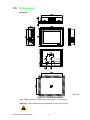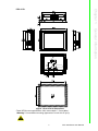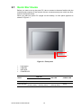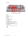
1
User Manual PPC-6150/6170 Intel® Core i3,i5/Celeron 847E processor based microcomputer, with 15"/17" color TFT LCD display Copyright The documentation and the software included with this product are copyrighted 2013 by Advantech Co., Ltd. All rights are reserved. Advantech Co., Ltd. reserves the right to make improvements in the products described in this manual at any time without notice. No part of this manual may be reproduced, copied, translated or transmitted in any form or by any means without the prior written permission of Advantech Co., Ltd. Information provided in this manual is intended to be accurate and reliable. However, Advantech Co., Ltd. assumes no responsibility for its use, nor for any infringements of the rights of third parties, which may result from its use. Acknowledgements Intel and Pentium are trademarks of Intel Corporation. Microsoft Windows is registered trademark of Microsoft Corp. All other product names or trademarks are properties of their respective owners. Product Warranty (2 years) Advantech warrants to you, the original purchaser, that each of its products will be free from defects in materials and workmanship for two years from the date of purchase. This warranty does not apply to any products which have been repaired or altered by persons other than repair personnel authorized by Advantech, or which have been subject to misuse, abuse, accident or improper installation. Advantech assumes no liability under the terms of this warranty as a consequence of such events. Because of Advantech’s high quality-control standards and rigorous testing, most of our customers never need to use our repair service. If an Advantech product is defective, it will be repaired or replaced at no charge during the warranty period. For outof-warranty repairs, you will be billed according to the cost of replacement materials, service time and freight. Please consult your dealer for more details. If you think you have a defective product, follow these steps: 1. Collect all the information about the problem encountered. (For example, CPU speed, Advantech products used, other hardware and software used, etc.) Note anything abnormal and list any onscreen messages you get when the problem occurs. 2. Call your dealer and describe the problem. Please have your manual, product, and any helpful information readily available. 3. If your product is diagnosed as defective, obtain an RMA (return merchandize authorization) number from your dealer. This allows us to process your return more quickly. 4. Carefully pack the defective product, a fully-completed Repair and Replacement Order Card and a photocopy proof of purchase date (such as your sales receipt) in a shippable container. A product returned without proof of the purchase date is not eligible for warranty service. 5. Write the RMA number visibly on the outside of the package and ship it prepaid to your dealer. PPC-6150/6170 User Manual Part No. 200K617020 Edition 1 Printed in China March 2013 ii Declaration of Conformity CE This product has passed the CE test for environmental specifications when shielded cables are used for external wiring. We recommend the use of shielded cables. This kind of cable is available from Advantech. Please contact your local supplier for ordering information. CE This product has passed the CE test for environmental specifications. Test conditions for passing included the equipment being operated within an industrial enclosure. In order to protect the product from being damaged by ESD (Electrostatic Discharge) and EMI leakage, we strongly recommend the use of CE-compliant industrial enclosure products. FCC Class A Note: This equipment has been tested and found to comply with the limits for a Class A digital device, pursuant to part 15 of the FCC Rules. These limits are designed to provide reasonable protection against harmful interference when the equipment is operated in a commercial environment. This equipment generates, uses, and can radiate radio frequency energy and, if not installed and used in accordance with the instruction manual, may cause harmful interference to radio communications. Operation of this equipment in a residential area is likely to cause harmful interference in which case the user will be required to correct the interference at his own expense. Technical Support and Assistance 1. 2. Visit the Advantech web site at http://support.advantech.com where you can find the latest information about the product. Contact your distributor, sales representative, or Advantech's customer service center for technical support if you need additional assistance. Please have the following information ready before you call: – Product name and serial number – Description of your peripheral attachments – Description of your software (operating system, version, application software, etc.) – A complete description of the problem – The exact wording of any error messages iii PPC-6150/6170 User Manual Safety Instructions 1. 2. 3. Read these safety instructions carefully. Keep this User Manual for later reference. Disconnect this equipment from any AC outlet before cleaning. Use a damp cloth. Do not use liquid or spray detergents for cleaning. 4. For plug-in equipment, the power outlet socket must be located near the equipment and must be easily accessible. 5. Keep this equipment away from humidity. 6. Put this equipment on a reliable surface during installation. Dropping it or letting it fall may cause damage. 7. The openings on the enclosure are for air convection. Protect the equipment from overheating. DO NOT COVER THE OPENINGS. 8. Make sure the voltage of the power source is correct before connecting the equipment to the power outlet. 9. Position the power cord so that people cannot step on it. Do not place anything over the power cord. 10. All cautions and warnings on the equipment should be noted. 11. If the equipment is not used for a long time, disconnect it from the power source to avoid damage by transient overvoltage. 12. Never pour any liquid into an opening. This may cause fire or electrical shock. 13. Never open the equipment. For safety reasons, the equipment should be opened only by qualified service personnel. 14. If one of the following situations arises, get the equipment checked by service personnel: The power cord or plug is damaged. Liquid has penetrated into the equipment. The equipment has been exposed to moisture. The equipment does not work well, or you cannot get it to work according to the user's manual. The equipment has been dropped and damaged. The equipment has obvious signs of breakage. 15. DO NOT LEAVE THIS EQUIPMENT IN AN ENVIRONMENT WHERE THE STORAGE TEMPERATURE MAY GO BELOW -20° C (-4° F) OR ABOVE 60° C (140° F). THIS COULD DAMAGE THE EQUIPMENT. THE EQUIPMENT SHOULD BE IN A CONTROLLED ENVIRONMENT. 16. CAUTION: DANGER OF EXPLOSION IF BATTERY IS INCORRECTLY REPLACED. REPLACE ONLY WITH THE SAME OR EQUIVALENT TYPE RECOMMENDED BY THE MANUFACTURER, DISCARD USED BATTERIES ACCORDING TO THE MANUFACTURER'S INSTRUCTIONS. The sound pressure level at the operator's position according to IEC 704-1:1982 is no more than 70 dB (A). DISCLAIMER: This set of instructions is given according to IEC 704-1. Advantech disclaims all responsibility for the accuracy of any statements contained herein. PPC-6150/6170 User Manual iv Safety Precaution - Static Electricity Follow these simple precautions to protect yourself from harm and the products from damage. To avoid electrical shock, always disconnect the power from your PC chassis before you work on it. Don't touch any components on the CPU card or other cards while the PC is on. Disconnect power before making any configuration changes. The sudden rush of power as you connect a jumper or install a card may damage sensitive electronic components. Power Warning The power is only fit for areas with an altitude of 2000 M below. v PPC-6150/6170 User Manual PPC-6150/6170 User Manual vi Contents Chapter 1 General Information ............................1 1.1 1.2 Introduction ............................................................................................... 2 Specifications ............................................................................................ 2 1.2.1 Specification Comparison ............................................................. 2 1.2.2 General Specifications .................................................................. 3 1.2.3 Power Specifications..................................................................... 3 1.2.4 Touchscreen Specifications .......................................................... 4 1.2.5 Environment Specifications........................................................... 4 1.2.6 Certification Specifications............................................................ 4 1.2.7 IP .................................................................................................. 4 Dimensions ............................................................................................... 6 Figure 1.1 PPC-6150 dimensions................................................ 6 Figure 1.2 PPC-6170 dimensions................................................ 7 1.3 Chapter 2 System Installation & Setup ...............9 2.1 Quick Start Guide.................................................................................... 10 Figure 2.1 Front panel ............................................................... 10 Figure 2.2 Side view .................................................................. 11 Figure 2.3 Location of I/O interfaces.......................................... 12 HDMI Specifications................................................................................ 13 Figure 2.4 .................................................................................. 13 Figure 2.5 .................................................................................. 13 Install Memory Card ................................................................................ 14 Figure 2.6 After removing rear cover ......................................... 14 Figure 2.7 .................................................................................. 14 Figure 2.8 .................................................................................. 15 Figure 2.9 .................................................................................. 15 Figure 2.10.................................................................................. 15 Figure 2.11.................................................................................. 16 Install ODD.............................................................................................. 16 Figure 2.12.................................................................................. 16 Figure 2.13.................................................................................. 17 Install HDD .............................................................................................. 17 2.5.1 Install HDD1:............................................................................... 17 Figure 2.14.................................................................................. 17 Figure 2.15.................................................................................. 18 Figure 2.16.................................................................................. 18 Figure 2.17.................................................................................. 18 Figure 2.18.................................................................................. 19 2.5.2 Install HDD2................................................................................ 19 Figure 2.19.................................................................................. 19 Figure 2.20.................................................................................. 20 Figure 2.21.................................................................................. 20 Figure 2.22.................................................................................. 21 Figure 2.23.................................................................................. 21 Install Mini SATA and Wireless Network Card ....................................... 22 Figure 2.24.................................................................................. 22 Figure 2.25.................................................................................. 23 2.6.1 Install MiNi SATA ........................................................................ 24 Figure 2.26.................................................................................. 24 2.6.2 Install Wireless LAN Long Card .................................................. 24 Figure 2.27.................................................................................. 24 Figure 2.28.................................................................................. 25 2.2 2.3 2.4 2.5 2.6 vii PPC-6150/6170 User Manual 2.7 2.8 2.9 Chapter 3 Jumper Configuration ...................... 33 3.1 Jumper & Connectors ............................................................................. 34 3.1.1 PCM-8207................................................................................... 34 Figure 3.1 PCM-8207 front view................................................ 34 3.1.2 MIO-5290.................................................................................... 36 Figure 3.2 MIO-5290 front view ................................................. 36 Figure 3.3 MIO-5290 rear view.................................................. 36 External COM PORT & DIO Switch and PIN Definition .......................... 38 Figure 3.4 COM ports ................................................................ 38 External Port DIO and COM5 Switch...................................................... 40 Figure 3.5 ................................................................................. 40 Figure 3.6 ................................................................................. 41 Figure 3.7 ................................................................................. 41 Touchscreen Control Source Configuration............................................ 42 Figure 3.8 ................................................................................. 42 Figure 3.9 ................................................................................. 42 3.2 3.3 3.4 Chapter Figure 2.29 ................................................................................. 25 Figure 2.30 ................................................................................. 26 Figure 2.31 ................................................................................. 26 Figure 2.32 ................................................................................. 27 2.6.3 Install Wireless LAN Short Card ................................................. 27 Figure 2.33 ................................................................................. 27 Figure 2.34 ................................................................................. 28 Figure 2.35 ................................................................................. 28 Figure 2.36 ................................................................................. 29 Figure 2.37 ................................................................................. 29 Install Riser Card .................................................................................... 30 Figure 2.38 ................................................................................. 30 Figure 2.39 ................................................................................. 30 Panel Mount Bracket Installation ............................................................ 31 Figure 2.40 ................................................................................. 31 Power Cable Bracket Installation ............................................................ 32 Figure 2.41 ................................................................................. 32 Figure 2.42 ................................................................................. 32 4 Software Configuration .................... 43 4.1 Install Divers ........................................................................................... 44 Figure 4.1 Divers in the CD-ROM.............................................. 44 BIOS Setup ............................................................................................. 45 4.2.1 Enter BIOS.................................................................................. 45 4.2.2 ATX & AT Mode Setup ............................................................... 46 4.2.3 Display Brightness Adjustment ................................................... 47 4.2.4 COM 232/422/485 Port .............................................................. 48 4.2.5 MiniPCIE & MiniSATA Configuration Method ............................. 50 4.2.6 PCIE Mode Select (x1, x4) ........................................................ 51 4.2.7 RAID Function Configuration ...................................................... 52 4.2.8 PCIE/RI Wakeup......................................................................... 53 4.2 Appendix A PCI/PCIE (Images) & Dual HDD RAID Function Configuration .................... 59 A.1 A.2 PCI/PCIE (Images) ................................................................................. 60 Dual HDD RAID ...................................................................................... 61 A.2.1 Windows XP Dual HDD RAID System Installation Procedures .. 61 PPC-6150/6170 User Manual viii A.2.2 Windows 7 Dual HDD RAID System Installation Procedures ..... 67 ix PPC-6150/6170 User Manual PPC-6150/6170 User Manual x Chapter 1 1 General Information This chapter gives background information on PPC-6150/6170 panel PC. Sections include: Introduction Specifications Dimensions 1.1 Introduction Advantech PPC-6150/6170 are Intel Core i3/i5 processor based panel PCs with 15" and 17" color LCD respectively. They feature powerful computing capability, modular design and excellent connection performance, almost fit for any application. In addition, they are also humanized information machine, which is highly represented by the user-friendly interface. For example, they have two expansion slots, dual HDDs, Intel RAID support, and an isolated RS-232/422 /485 port. These functions greatly improve the product reliability, and are able to satisfy most users' needs. 1.2 Specifications 1.2.1 Specification Comparison Product PPC-6150 PPC‐6170 LCD Specification 15’’ LCD 17’’ LCD Display Type 15" TFT LCD (LED backlight) 17" TFT LCD (LED backlight) Max. Resolution 1024 x 768 1280 x 1024 Color 262K 262K dot matrix 0.297 x 0.297mm 0.264 x 0.264mm Viewing Angle 80 (left), 80 (right), 80 (top), 60 (bottom) 85 (left), 85 (right) 80 (top), 80 (bottom) Brightness 350 cd/m2 350cd/m2 Contrast 700 1000 LCD Operation Temperature -30 ~ 85° C -30 ~ 85° C Backlight Lifecycle 50, 000 hours 50, 000 hours Weight 6.5 Kg (14.32 lb) 7.5 Kg (16.52 lb) Dimensions 395.5 x 316.8 x 105.5 (mm) (15.6" x 12.5" x 4.15") 442.0 x 362.0 x 113.5 (mm) (17.4" x 14.25" x 4.47") PPC-6150/6170 User Manual 2 Frequency 2.7 GHz 2.4 GHz 1.1 GHz Cache 4M 3M 2M Chipset Intel QM77 Memory One 204 pin SO-DIMM slot, up to 8 G DDR3 (1600 MHz) / DDRL (1333 MHz) Storage 1 2.5" SATA HDD 2.5" SATA HDD (support Intel RAID function) (optional) Storage 2 Support slim 8X or above DVD +/- RW (optional) 2 x Gigabit Ethernet ports, support Intel AMT (GbE1- Intel 82579LM,GbE2–Intel 82583V) Network 4 x COM port: 1 x isolated RS-232/422/485; 3 x RS232 1 x GPIO/RS-232 (8 channels, TTL level) 3 x USB3.0 + 2 x USB2.0 I/O Ports 2 x Gigabit Ethernet ports 1 x D-SUB VGA ports 1 x HDMI ports 1 x Line-out port,1 x Mic-in port, 2 x 1 W speaker (built-in) 1 x PCI + 1 x PCIe x1 (optional) Expansion Slot 1 x PCIe x4 (available in the accessory box) 2 x PCIe x1 (optional) 2 x PCI (optional) Additional Expansion 1 x mini PCIe long card slot (support mSATA) Slot 1 x mini PCIe half long card slot System Windows XPE / Windows XP Pro / Windows Embedded Standard 7 / Windows 7 1.2.3 Power Specifications Model PPC-6150 PPC-6170 Power (i5-3610ME) 61 W (test system: Windows7 32bit) 65 W (test system: Windows7 32bit) Power (i3-3210ME) 55 W (test system: Windows7 32bit) 50 W (test system: Windows XP 32bit) 60 W (test system: Windows XP 32bit) 55 W (test system: Windows7 32bit) 47 W (test system: Windows XP 32bit) 47 W (test system: Windows XP 32bit) 48 W (test system: Windows7 32bit) 53 W (test system: Windows7 32bit) Power (Celeron 847E) 35 W (test system: Windows XP 32bit) 39 W (test system: Windows XP 32bit) Output Power 150 W (Max.) Input Voltage 100-240 Vac, 50/60 Hz, 4 A ~ 2 A 3 PPC-6150/6170 User Manual General Information CPU Model No. Core i5-3610ME Core i3-3120ME Celeron 847E Chapter 1 1.2.2 General Specifications 1.2.4 Touchscreen Specifications Type 5-wire resistive Resolution 2048 x 2048 Light Transmission 81%+/-3% Controller COM interface (can be used as USB interface, use COM5 as controller source) Touchscreen Lifecycle 36,000,000 times 1.2.5 Environment Specifications Operation Temperature 0 ~ 50° C (32 ~ 122° F) Storage Temperature -20 ~ 60° C (-4 ~ 140° F) Relative Temperature 10 ~ 95% @ 40° C (non-condensing) Shock 10 G peak acceleration (11 msec duration) Vibration 5 ~ 500 Hz 1 G RMS 1.2.6 Certification Specifications EMC BSMI, CE, FCC Class A Safety CB, CCC, BSMI, UL 1.2.7 IP Front Panel IP Grade PPC-6150/6170 User Manual IP65 4 Test Software Test Configuration i5-3610ME @2.70 GHz Celeron 847E @ 1.1GHz Power (W) Windows 7 32bit 65 Windows XP 32bit 55 Windows 7 32bit 55 Windows XP 32bit 47 Windows 7 32bit 53 Windows XP 32bit 39 Note2: PPC-6150's power test conditions are as follows (for reference only, powers differ from different peripheral configurations) Test Software Test Configuration i5-3610ME @2.70 GHz Memory: Transcend DDR3 1600 SODIMM 8GBx1 HDD: Seagate ST250LT003 i3-3120ME @2.4 GHz Burn-in 7.0 9YG141C-500 250GB SATA 2.5” IO: COM Port RS232 loopback x5, USB3.0 device x5 Celeron847E @1.1 GHz 5 Test System Power (W) Windows 7 32bit 61 Windows XP 32bit 50 Windows 7 32bit 50 Windows XP 32bit 43 Windows 7 32bit 48 Windows XP 32bit 35 PPC-6150/6170 User Manual General Information Memory: Transcend DDR3 1600 SODIMM 8GBx1 HDD: Seagate ST250LT003 i3-3120ME @2.4 GHz Burn-in 7.0 9YG141C-500 250GB SATA 2.5” IO: COM Port RS232 loopback x5: USB3.0 device x5 Test System Chapter 1 Note 1: PPC-6170's power test conditions are as follows (for reference only, powers differ from different peripheral configurations) 1.3 Dimensions PPC-6150: Unit: mm Figure 1.1 PPC-6150 dimensions Fixed VESA screw specification: M4; screw depth: 7.5 mm (Max).. Warning! Use suitable mounting apparatus to avoid risk of injury. PPC-6150/6170 User Manual 6 Chapter 1 PPC-6170: General Information Figure 1.2 PPC-6170 dimensions Fixed VESA screw specification: M4; screw depth: 7.5 mm (Max).. Warning! Use suitable mounting apparatus to avoid risk of injury. 7 PPC-6150/6170 User Manual PPC-6150/6170 User Manual 8 Chapter 2 2 System Installation & Setup Sections include: Quick Installation Guide HDMI Specifications Install Memory Install ODD Install HDD Install MINI SATA and Wireless LAN Card Install Riser Card Panel Mount Bracket Installation Power Cable Bracket Installation 2.1 Quick Start Guide Before you start to set up the panel PC, take a moment to become familiar with the locations and purposes of the controls, drives, connectors and ports, which are illustrated in the figures below. When you place the panel PC upright on the desktop, its front panel appears as shown in Figure 2.1. 4 3 1 2 Figure 2.1 Front panel 1. 2. 3. 4. Light sense LAN LED HDD LED POWER LED LAN LED Status LAN1 Power Off (S5) Off Green Power On (S0) (working, blink) PPC-6150/6170 User Manual HDD LED POWER LED Off Yellow Yellow (working, blink) Green LAN2 Yellow (working, blink) 10 1 Chapter 2 2 2 4 5 6 Figure 2.2 Side view Red rectangle indicates VESA screw hole. 1. Air outlet 2. Antenna hole 3. Panel Mount Bracket hole (10 in PPC-6170, 8 in PPC-6150) 4. Slim type optical drive bay 5. Loudspeaker (dual) 6. Air inlet Note! Fixed VESA specification: M4; screw depth: 7.5 mm (Max). 11 PPC-6150/6170 User Manual System Installation & Setup 3 I/O interfaces: A B C D K4 E K3 G F K2 H K1 K J Figure 2.3 Location of I/O interfaces A: AC power B: Power C: 2 x USB 3.0, 2 x USB 2.0 D: Wire clasp E: HDMI port F: VGA port G: 2 x Gigabit Ethernet ports H: 2 x Expansion slots I: Line out/Mic in J: 1 x USB 3.0 interface K: DIO / COM5 port (by swapping pin header) K1: COM1(RS232,Pin9 supports 5 V/12 V output) K2: COM2(RS232/422/485,with isolation) K3: COM3(RS232,Pin9 supports 5 V/12 V output) K4: COM4(RS232) Note! Wire clasp dimension: 9 mm x 3.5 mm. PPC-6150/6170 User Manual 12 I 1. When using HDMI interface, please purchase cables of above 9 mm long (see Figure 2.4), or imperfect contact may happen. Figure 2.4 2. Please insert the cable by the right ride. (See Fig 2.5) Figure 2.5 13 PPC-6150/6170 User Manual System Installation & Setup Length: above 9mm Chapter 2 2.2 HDMI Specifications 2.3 Install Memory Card 1. Remove rear cover of the panel PC. (See Fig 2.6) Figure 2.6 After removing rear cover 2. Remove the two screws of the riser card (see Fig 2.7), and pull out the card. Figure 2.7 PPC-6150/6170 User Manual 14 Remove all the screws in the reinforced board, including the three screws beside the fan (see Fig 2.8) and the one in I/O stop plate. System Installation & Setup Figure 2.8 4. Remove the reinforced board. (see Fig 2.9) Figure 2.9 5. Remove CPU fan cable and the 4 screws in CPU cooler and take out the CPU cooler. Figure 2.10 15 Chapter 2 3. PPC-6150/6170 User Manual 6. Insert the memory card in the slot, and take out the thermal pads of CPU, QM77 and memory and stick them in the correct locations (see Fig 2.11), then install the CPU cooler to complete the memory installation. 1 3 2 Figure 2.11 2.4 Install ODD 1. Remove the four screws as shown in Fig 2.12, and take out the HDD2 bracket. Figure 2.12 PPC-6150/6170 User Manual 16 Take out ODD module, fix it onto the iron bracket, and connect the ODD cable to the corresponding interface.(See Fig 2.13) 2.5 Install HDD 2.5.1 Install HDD1: 1. 2. Please follow the procedures 1-4 in Section 2.3. Take down the HDD hold-down clamp. (See Fig 2.14) Figure 2.14 17 PPC-6150/6170 User Manual System Installation & Setup Figure 2.13 Chapter 2 2. 3. Take down the HDD U type bracket. (See Fig 2.15) Figure 2.15 4. Take out the 4 screws, lock HDD onto the U type bracket (screws can be found in the accessory box, 4 x M3X4), and insert HDD cable into HDD module. (See Fig 2.16) Figure 2.16 5. Return to the original position. (See Fig 2.17) Figure 2.17 PPC-6150/6170 User Manual 18 Connect HDD cable to the mainboard. (See Fig 2.18). 2.5.2 Install HDD2 1. 2. Please follow the procedures 1-4 in Section 2.3. Take out the U type bracket, 4 black washers, 4 transparent washers and 2 HDD hold-down clamps (with black foams attached). (See Fig 2.19) Figure 2.19 19 PPC-6150/6170 User Manual System Installation & Setup Figure 2.18 Chapter 2 6. 3. Position the 8 washers as shown in Fig 2.20. Please make sure the transparent washer U card is fixed in the U iron bracket, or HDD may be damaged easily. Figure 2.20 4. Take out 4 M3*4 screws, fix the HDD lock onto U type iron bracket, and insert the power cable. (See Fig 2.21) Figure 2.21 PPC-6150/6170 User Manual 20 Lock the hold-down clamp onto U type iron bracket with the 4 M3*4 screws, and fix the HDD onto HDD2 iron bracket. System Installation & Setup Figure 2.22 6. Connect the HDD cable. (See Fig 2.23) Figure 2.23 21 Chapter 2 5. PPC-6150/6170 User Manual 2.6 Install Mini SATA and Wireless Network Card (The following installation procedures are only for professional technicists’ reference. The screws needed in this process can be found in the accessory box. 1. Please follow the procedures in Section 2.3. 2. Untie USB cable, and then remove the cable and two screws in MIO mainboard. Figure 2.24 PPC-6150/6170 User Manual 22 Unplug the cables beside the IO as shown below, and remove the 2 hexagonal screws in VGA of I/O back plate. Then vertically pull out MIO board. (See Fig 2.25) 5 4 3 6 8 7 9 10 Figure 2.25 23 PPC-6150/6170 User Manual System Installation & Setup 2 1 Chapter 2 3. The steps to install the card are as follows. Please follow the corresponding steps to install. Part A. Install MiNi SATA; Part B: Install wireless LAN long card; Part C. Install wireless LAN short card 2.6.1 Install MiNi SATA 1. Insert MiNi SATA card into PCIE slot, and fix it with two M2x 6. (See Fig 2.17) Note! Wireless LAN long card and MiNi SATA slot share one slot. Users need to configure the port as Mini SATA by BIOS, please refer to "BIOS Configuration" chapter for the details. Figure 2.26 2.6.2 Install Wireless LAN Long Card 1. First take down wireless LAN card antenna bracket. (See Fig 2.27) Figure 2.27 PPC-6150/6170 User Manual 24 Fixed the antenna onto the bracket. (See Fig2.28) Chapter 2 2. 3. Lock the bracket with antenna onto M/B frame, the wiring method is shown as Fig 2.29. The antenna receiver is locked onto the antenna terminal. (See Fig 2.30) Figure 2.29 25 PPC-6150/6170 User Manual System Installation & Setup Figure 2.28 Figure 2.30 4. Take out two M2 X 6 screws from the accessory box, and insert the wireless LAN card into MIO-5290 CN28 slot. Note! Long card and MiNi SATA slot share one slot. Users need to configure the port as PCIE by BIOS, please refer to "BIOS Configuration" chapter for the details. Figure 2.31 PPC-6150/6170 User Manual 26 Connect the antenna to wireless LAN card, the wiring method of the long card is shown as Fig 2.32. 2.6.3 Install Wireless LAN Short Card 1. 2. Follow the procedures in Section 2.6.2, and install the antenna to the machine. Take out one M2 X 6 screw from the accessory box, and lock the short card into MIO-5290 CN29 card slot. (See Fig 2.33) Figure 2.33 27 PPC-6150/6170 User Manual System Installation & Setup Figure 2.32 Chapter 2 5. 3. Connect the antenna to wireless LAN card, the wiring method of wireless LAN card is shown as Fig 2.34. Figure 2.34 4. Reinstall MIO mainboard, lock the screws and return back the cables according to Procedure 3-6, then check if all cables are correctly connected, which is shown as Fig2.35, 2.36 and 2.37 respectively. 5. Lock the cooler onto MIO mainboard and connect the MIO fan cable. (See Fig 2.35) Figure 2.35 PPC-6150/6170 User Manual 28 Connect the USB cable. (See Fig2.36) Chapter 2 6. 7. Lock the reinforced board and connect the fan cable, and check if the left system fan cable is connected well. (See Fig 2.37) Figure 2.37 8. Lock the reinforced board, riser card and rear cover to complete the installation. 29 PPC-6150/6170 User Manual System Installation & Setup Figure 2.36 2.7 Install Riser Card (See the appendix for card image) When using PCM-916, users need to configure PPCIEx1 interface as“PCIE x4” Mode. When using PCM-917/918/920, users need to configure PPCIEx1 interface as “PCIE x1” Mode For PPCIE interface configuration, please refer to "PCIE Mode Selection (x1, x4)" in "BIOS Configuration" chapter. 1. Remove the rear cover of panel PC. 2. Insert the riser card into the slot, and lock the two screws.(See Figure 2.38) Figure 2.38 3. Remove the card slot back plate, and insert the needed card (See Fig 2.33), then fixed the screws and return back the rear cover. Figure 2.39 PPC-6150/6170 User Manual 30 Chapter 2 2.8 Panel Mount Bracket Installation Please follow the figures below: Panel System Installation & Setup Panel Figure 2.40 31 PPC-6150/6170 User Manual 2.9 Power Cable Bracket Installation 1. Insert the power cable into the power interface. Figure 2.41 2. Lock the power cable bracket onto the machine which is shown as the figure below. 2 M3X5 2 screws Figure 2.42 3. When using power bracket, please select the power cable with correct connecter. The dimension of the bracket is shown as below: PPC-6150/6170 User Manual 32 Chapter 3 3 Jumper Configuration Sections include: Jumper & Connectors Peripheral COM Port & DIO Switch and Pin Definitions Peripheral DIO and COM5 Port Switch Touchscreen Control Source Configuration 3.1 Jumper & Connectors 3.1.1 PCM-8207 Figure 3.1 PCM-8207 front view Connectors Functions CN2 ATX POWER SYSFAN2 3PIN FAN CN4/CN5 SATA POWER CN33 LED driver board CN8 Backlight enable CN37 USB for touch CN10 Light sense CN59 COM5 (RS232, default for Touch) CN12 DIO CN13 LCD size select CN17 Touch CN18 LPT Port CN21 Speaker CN20 Audio CN19 Pin9 power select (COM1&COM3) JP1&JP2 Touch source select PPCIE1 PCIEx4 (non standard) PPC-6150/6170 User Manual 34 Images LCD Selection (1-2) P1 17” LCD (3-4) P2 15” LCD CN19 Images Configuration Image P2 COM1/COM3 Pin9 Power Selection Function (1-3) (2-4) (Default) P3 RI (5-7) P4 5 V (COM2 Pin9) (+/-10%, maximum 0.5 A) (7-9) P5 12 V (COM1 Pin9) (+/-10%, maximum 0.25 A) (6-8) P6 5 V (COM2 Pin9) (+/-10%, maximum 0.5 A) (8-10) P7 12 V (COM2 Pin9) (+/-10%, maximum 0.25 A) Image P3 Image P4 Image P5 Image P6 JP1&JP2 Images Touch Source Selection JP1 (5-9), JP1 (6-10) JP1 (7-11), JP1 (8-12) JP2 (1-5), JP2 (2-6) JP2 (3-7), JP2 (4-8) P8 (Default) COM5 control JP1(1-5), JP1 (2-6) JP1 (3-7), JP1 (4-8) JP2(5-9), JP2 (6-10) JP2(7-11), JP1 (8-12) P9 USB control COM Port (default) Image P7 USB interface Image P8 Image P9 35 PPC-6150/6170 User Manual Jumper Configuration Image P1 Chapter 3 CN13 3.1.2 MIO-5290 Top Figure 3.2 MIO-5290 front view Bottom Figure 3.3 MIO-5290 rear view PPC-6150/6170 User Manual 36 Chapter 3 Functions CN12 Memory CN7/CN8 SATA CN9 Audio CN3 Backlight enable CN1 Power button J1 Clear CMOS J2 ATX&AT select CN11 LED board FAN1 CPU FAN FAN2 Power FAN CN18 ATX 4PIN 12V POWER CN14 LVDS J3 LVDS Power select J4 DDR3 POWER select CN13 USB CN28 Full Mini PCIE or Mini SATA (Selected by BIOS) CN29 Half Mini PCIE J1 Images For Clear CMOS Configuration Functions (1-2) P10 Keep CMOS (Default) (2-3) P11 Clear CMOS Image P10 J2 Images Image P11 For ATX & AT Select Configuration Functions On(1-2) P12 AT mode OFF(1-2) P13 ATX mode (Default) Image P12 J3 Images Image P13 For LVDS Power Select Configuration Functions (1-3) P14 15”LCD mode (3-5) P15 17”LCD mode 37 PPC-6150/6170 User Manual Jumper Configuration Connectors Image P14 J4 Image P15 Images For DDR3 Power Select Configuration Functions On (1-2) P15 DDR3L mode OFF (1-2) P16 DDR3 mode (Default) Image P16 Image P17 3.2 External COM PORT & DIO Switch and PIN Definition (Open the rear cover before configuration) K4 K3 K2 K1 K Figure 3.4 COM ports K: DIO / COM5 port (by swapping pin header) K1: COM1(RS232, pin9 supports 5 V/12 V output) K2: COM2(RS232/422/485, with isolation) K3: COM3(RS232, pin9 supports 5 V/12 V output) K4: COM4 (RS232) PPC-6150/6170 User Manual 38 Jumper Configuration DIO: 1. Operation voltage 5 V+/-10%. 2. 8 bit parallel input and output port. 3. Control signal is SMBUS. External COM PORT & DIO PIN definition: Ports Functions Pin RS232 1 DCD 422_TXD- 485_Data- GND 2 RXD 422_TXD+ 485_Data+ GPIO4 3 TXD 422_RXD+ GPIO0 4 DTR 422_RXD- GPIO5 5 GND GND GPIO1 6 DSR GPIO6 7 RTS GPIO2 8 CTS GPIO7 9 RIC GPIO3 RS422 39 Chapter 3 COM2: 1. The operation mode can be either RS232/422/485, selected by BIOS. (For details, please refer to "232/422/485 COM PORT" in "BIOS Configuration" chapter. 2. This port is designed with isolation function (1000 VDC). RS485 DIO PPC-6150/6170 User Manual 3.3 External Port DIO and COM5 Switch 1. ? Configure the external port as DIO (default). Figure 3.5 PPC-6150/6170 User Manual 40 Configure the external port as COM5. (See Fig 3.6) a. Configure JP1 and JP2 as shown in Fig 3.6. (This configuration will change touchscreen's control source as USB, and the system needs to reinstall touchscreen driver.) Jumper Configuration Figure 3.6 b. Connect the cable to COM5. (See Fig 3.7) Figure 3.7 41 Chapter 3 2. PPC-6150/6170 User Manual 3.4 Touchscreen Control Source Configuration (Open the rear cover first) 1. Use COM5 port to control touchscreen. (Default) Take down DIO cable, and configure JP&JP2 as shown in Fig 3.8, then insert the DIO cable. Figure 3.8 2. Use USB to control touchscreen. Take down DIO cable, and configure JP&JP2 as shown in the figure below, then insert the DIO cable. Figure 3.9 PPC-6150/6170 User Manual 42 Chapter 4 Software Configuration Sections include: Install Drivers BIOS Setup Program 4 4.1 Install Divers When first using the system, users need to set up corresponding drivers, in order to ensure all functions are normal. Please take out the CD-ROM from the accessory box and open it in the system, the below folder will be shown: Figure 4.1 Divers in the CD-ROM All needed drivers are included in the CD-ROM, both Windows 7 and Windows XP systems can be used in all drivers except VGA. Intel RAID_AHCI: All drivers needed to install during RAID assembly PPC Backlight Adjustment Tool: Customers can use this program to adjust the LCD brightness in the system to optimize the display effect. For details please refer to "User manual" in this folder. User manual: E-record of the user manual for this machine. Please follow the instructions to install the drivers. The drivers in the accompanied CD-ROM may not be the latest version, if needed, please find it at: http://www.advantech.com.cn/ PPC-6150/6170 User Manual 44 4.2.1 Enter BIOS Start the computer and press "Delete" key to enter BIOS. Press "F4" to save and exit after any configuration, or the configuration won't be saved in BIOS. Chapter 4 4.2 BIOS Setup Software Configuration 45 PPC-6150/6170 User Manual 4.2.2 ATX & AT Mode Setup 1. Select “PCH-IO Configuration” under “Chipset”. 2. Configure “Restore AC Power Loss” as “Power On”. PPC-6150/6170 User Manual 46 Chapter 4 4.2.3 Display Brightness Adjustment Select “Chipset” under “Brightness Control”. Software Configuration A.Manual Adjustment Mode “LCD Brightness Control” is configured as “Manual Mode” by default. Select “Brightness Manual Control” under “Brightness Control”, and there will be 6 options: 47 PPC-6150/6170 User Manual B. Auto Sensor Adjustment Mode “LCD Brightness Control” is configured as "Dynamic Mode", that is, auto sensor adjustment mode. Then the machine will automatically adjust the LCD brightness from sensor points. 4.2.4 COM 232/422/485 Port 1. Select “Advanced” under “Super IO Configuration”. PPC-6150/6170 User Manual 48 Then Select “Serial Port 2 Configuration”. 3. Then you can select the operation mode of COM2 by "Serial Port2 Mode". PPC-6150/6170 User Manual Software Configuration 49 Chapter 4 2. 4.2.5 MiniPCIE & MiniSATA Configuration Method 1. Select "Chipset" under "PCH-IO Configuration". 2. Then select "MINI Card/M-SATA". PPC-6150/6170 User Manual 50 Enter and select MINI PCIE type. Mini Card: CN28 is of Mini PCIE interface. M-SATA: CN28 is of Mini SATA interface. Chapter 4 3. Software Configuration 4.2.6 PCIE Mode Select (x1, x4) 1. Select "Chipset" under "PCIE Port Configuration". 51 PPC-6150/6170 User Manual 2. Enter and select PCIE mode as x1 or x4. PCIE X1: PPCIEX1 interface includes 4 PCIEx1 interface. (Users need to set this mode when using PCM-917/918/920) PCIE X4: PPCIEX1 interface includes 1 PCIEx4 interface. (Users need to set this mode when using PCM-916) 4.2.7 RAID Function Configuration 1. Select "SATA Configuration" under "Advanced". PPC-6150/6170 User Manual 52 Then select "RAID" in "SATA Mode Selection". Chapter 4 2. Software Configuration 4.2.8 PCIE/RI Wakeup 1. Select “Chipset” under “PCH-IO Configuration”. 53 PPC-6150/6170 User Manual 2. Select “Wake on PCIE/RI” as “Enabled” under “PCH-IO Configuration”. 3. Open wake on LAN function in the system. A. Open wake on LAN function in windows 7. Right click “Computer” and select “Manage” to enter management interface, then select “Device Manager”. PPC-6150/6170 User Manual 54 Chapter 4 Select “Network adapters”, and 2 network devices will appear. Select any device with wake on LAN function, and right click to select “Properties”. Software Configuration Select “Power Management”, and remember to check “Wake on Magic Packet” and “Wake on Magic Packet from power off state”. 55 PPC-6150/6170 User Manual B. Open wake on LAN function in windows XP. Right click “Computer” and select “Manage” to enter management interface, then select “Network adapters”, and 2 network devices will appear. Select any device with wake on LAN function, and right click to select “Properties”. PPC-6150/6170 User Manual 56 Chapter 4 Select “Power Management”, and remember to check “Wake on Magic Packet” and “Wake on Magic Packet from power off state”. Software Configuration 57 PPC-6150/6170 User Manual PPC-6150/6170 User Manual 58 Appendix A A PCI/PCIE (Images) & Dual HDD RAID Function Configuration A.1 PCI/PCIE (Images) PCM-916 1-PCIEX4 slot (in the accessory box) PCM-917 2-PCIEX1 slot (optional) PCM-918 2-PCI32 slot (optional) PCM-920 1-PCIEX1&1-PCI32 slot (default) PPC-6150/6170 User Manual 60 The size of PCI and PCIE card can not exceed 208 mm long, and 105 mm wide. The total current load provided by the expansion slot is as follows: 12 V 2A 5V 2A 3.3 V 3A -12 V 100 mA Total output voltage of 12 V, 5 V and 3.3 V can not exceed 25 W. A.2 Dual HDD RAID A.2.1 Windows XP Dual HDD RAID System Installation Procedures 1. 2. Enter BIOS and set SATA mode as RAID. Please press “Ctrl+I” to enter RAID screen during bootup. 61 PPC-6150/6170 User Manual Appendix A PCI/PCIE (Images) & Dual HDD RAID Function Configuration Note! 3. Select “Create RAID Volume” to create RAID. Users can choose RAID0 or RAID1 mode here. 4. Select “Create Volume” after mode configuration, and you’ll be reminded that RAID HDD data will be erased. Press “Y” to confirm selecting RAID mode. PPC-6150/6170 User Manual 62 Select “Exit” and press “Y” to exit the screen. 6. Then it will boot from CD-ROM. Press “F6” to wait loading RAID driver. 63 PPC-6150/6170 User Manual Appendix A PCI/PCIE (Images) & Dual HDD RAID Function Configuration 5. 7. You can press “S” to select the driver when “loading driver” appears. Please select “Intel (R) Mobile Express Chipset SATA RAID Controller” and press “Enter” to continue. PPC-6150/6170 User Manual 64 Press “Enter” to continue. 9. Press “Enter” to prepare installing system. 65 Appendix A PCI/PCIE (Images) & Dual HDD RAID Function Configuration 8. PPC-6150/6170 User Manual 10. Press “F8” to agree starting installation. 11. It will appear the total HDD size after RAID configuration, then you can create partition by your favorite. PPC-6150/6170 User Manual 66 A.2.2 Windows 7 Dual HDD RAID System Installation Procedures The preparation procedures of Windows 7 installation is the same as that of Windows XP. Users need to configure dual HDD as RAID mode and then start installation. It will continue introducing from the above step 5 here. 1. Continue with Step 5, boot from CD-ROM, and continue installation according to the instructions. It will appear the HDDs with RAID successfully configured. 67 PPC-6150/6170 User Manual Appendix A PCI/PCIE (Images) & Dual HDD RAID Function Configuration 12. Finally wait until copying all files, and complete the installation according to the instructions. 2. You can create partition by your favorite and continue installation. 3. Click “Next” to continue and complete the installation. PPC-6150/6170 User Manual 68 Appendix A PCI/PCIE (Images) & Dual HDD RAID Function Configuration PPC-6150/6170 User Manual 69 www.advantech.com Please verify specifications before quoting. This guide is intended for reference purposes only. All product specifications are subject to change without notice. No part of this publication may be reproduced in any form or by any means, electronic, photocopying, recording or otherwise, without prior written permission of the publisher. All brand and product names are trademarks or registered trademarks of their respective companies. © Advantech Co., Ltd. 2013