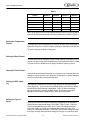
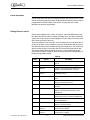
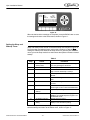
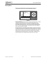
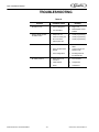
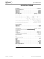
1
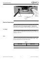
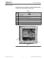
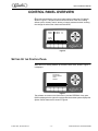
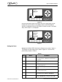
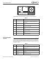
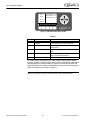
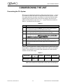
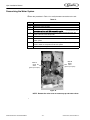
FRUTISTA VIPER 3 FLAVOR Installation Manual Release Date: April 2, 2010 Publication Number: 621360041TBINS Revision Date: May 09, 2012 Revision: D Visit the IMI Cornelius web site at www.cornelius.com for all your Literature needs. The products, technical information, and instructions contained in this manual are subject to change without notice. These instructions are not intended to cover all details or variations of the equipment, nor to provide for every possible contingency in the installation, operation or maintenance of this equipment. This manual assumes that the person(s) working on the equipment have been trained and are skilled in working with electrical, plumbing, pneumatic, and mechanical equipment. It is assumed that appropriate safety precautions are taken and that all local safety and construction requirements are being met, in addition to the information contained in this manual. This Product is warranted only as provided in Cornelius’ Commercial Warrant applicable to this Product and is subject to all of the restrictions and limitations contained in the Commercial Warranty. Cornelius will not be responsible for any repair, replacement or other service required by or loss or damage resulting from any of the following occurrences, including but not limited to, (1) other than normal and proper use and normal service conditions with respect to the Product, (2) improper voltage, (3) inadequate wiring, (4) abuse, (5) accident, (6) alteration, (7) misuse, (8) neglect, (9) unauthorized repair or the failure to utilize suitably qualified and trained persons to perform service and/or repair of the Product, (10) improper cleaning, (11) failure to follow installation, operating, cleaning or maintenance instructions, (12) use of “non-authorized” parts (i.e., parts that are not 100% compatible with the Product) which use voids the entire warranty, (13) Product parts in contact with water or the product dispensed which are adversely impacted by changes in liquid scale or chemical composition. Contact Information: To inquire about current revisions of this and other documentation or for assistance with any Cornelius product contact: www.cornelius.com 800-238-3600 Trademarks and Copyrights: This document contains proprietary information and it may not be reproduced in any way without permission from Cornelius. Printed in U.S.A. TABLE OF CONTENTS Introduction . . . . . . . . . . . . . . . . . . . . . . . . . . . . . . . . . . . . . . . . . . . . . . . . . . . . . . . . . . . . . . . . . . . . . . 1 System Overview . . . . . . . . . . . . . . . . . . . . . . . . . . . . . . . . . . . . . . . . . . . . . . . . . . . . . . . . . . . . . . . 1 Introduction . . . . . . . . . . . . . . . . . . . . . . . . . . . . . . . . . . . . . . . . . . . . . . . . . . . . . . . . . . . . . . . . . 1 Safety Instructions. . . . . . . . . . . . . . . . . . . . . . . . . . . . . . . . . . . . . . . . . . . . . . . . . . . . . . . . . . . . . . . . . 2 Read and Follow ALL Safety Instructions . . . . . . . . . . . . . . . . . . . . . . . . . . . . . . . . . . . . . . . . . . . . . 2 Safety Overview . . . . . . . . . . . . . . . . . . . . . . . . . . . . . . . . . . . . . . . . . . . . . . . . . . . . . . . . . . 2 Recognition . . . . . . . . . . . . . . . . . . . . . . . . . . . . . . . . . . . . . . . . . . . . . . . . . . . . . . . . . . . . . . 2 Different Types of Alerts . . . . . . . . . . . . . . . . . . . . . . . . . . . . . . . . . . . . . . . . . . . . . . . . . . . . . . . 2 Safety Tips . . . . . . . . . . . . . . . . . . . . . . . . . . . . . . . . . . . . . . . . . . . . . . . . . . . . . . . . . . . . . . . . . . . . 2 Qualified Service Personnel . . . . . . . . . . . . . . . . . . . . . . . . . . . . . . . . . . . . . . . . . . . . . . . . . . . . . . . 3 Safety Precautions . . . . . . . . . . . . . . . . . . . . . . . . . . . . . . . . . . . . . . . . . . . . . . . . . . . . . . . . . . . . . . 3 Shipping And Storage . . . . . . . . . . . . . . . . . . . . . . . . . . . . . . . . . . . . . . . . . . . . . . . . . . . . . . . . . . . . 3 CO2 (Carbon Dioxide) Warning . . . . . . . . . . . . . . . . . . . . . . . . . . . . . . . . . . . . . . . . . . . . . . . . . . . . 4 Mounting in or on a Counter . . . . . . . . . . . . . . . . . . . . . . . . . . . . . . . . . . . . . . . . . . . . . . . . . . . . . . . 4 Dispensed Product Conditions . . . . . . . . . . . . . . . . . . . . . . . . . . . . . . . . . . . . . . . . . . . . . . . . . . . . . 4 Overrun, as Applied to Carbonated Beverages . . . . . . . . . . . . . . . . . . . . . . . . . . . . . . . . . . . . . 4 Overrun Definition . . . . . . . . . . . . . . . . . . . . . . . . . . . . . . . . . . . . . . . . . . . . . . . . . . . . . . . . . Overrun is a Variable . . . . . . . . . . . . . . . . . . . . . . . . . . . . . . . . . . . . . . . . . . . . . . . . . . . . . . Specific Product Ingredients Affect Overrun . . . . . . . . . . . . . . . . . . . . . . . . . . . . . . . . . . . . . BRIX Affects Overrun . . . . . . . . . . . . . . . . . . . . . . . . . . . . . . . . . . . . . . . . . . . . . . . . . . . . . . Low Dispensing Volume Affects Overrun . . . . . . . . . . . . . . . . . . . . . . . . . . . . . . . . . . . . . . . Carbonation Level in Liquid Product Affects Overrun . . . . . . . . . . . . . . . . . . . . . . . . . . . . . . Freezing Affects Overrun . . . . . . . . . . . . . . . . . . . . . . . . . . . . . . . . . . . . . . . . . . . . . . . . . . . Installation . . . . . . . . . . . . . . . . . . . . . . . . . . . . . . . . . . . . . . . . . . . . . . . . . . . . . . . . . . . . . . . . . . . . . . . 4 4 5 5 5 5 5 6 Delivery, Inspection & Unpacking . . . . . . . . . . . . . . . . . . . . . . . . . . . . . . . . . . . . . . . . . . . . . . . . . . . 6 Counter Location . . . . . . . . . . . . . . . . . . . . . . . . . . . . . . . . . . . . . . . . . . . . . . . . . . . . . . . . . . . . . . . . 6 Backroom Requirements . . . . . . . . . . . . . . . . . . . . . . . . . . . . . . . . . . . . . . . . . . . . . . . . . . . . . . . . . 7 Supply Connections . . . . . . . . . . . . . . . . . . . . . . . . . . . . . . . . . . . . . . . . . . . . . . . . . . . . . . . . . . . . . 7 Electrical Requirements . . . . . . . . . . . . . . . . . . . . . . . . . . . . . . . . . . . . . . . . . . . . . . . . . . . . . . . 8 Line Voltage . . . . . . . . . . . . . . . . . . . . . . . . . . . . . . . . . . . . . . . . . . . . . . . . . . . . . . . . . . . . . 8 Power . . . . . . . . . . . . . . . . . . . . . . . . . . . . . . . . . . . . . . . . . . . . . . . . . . . . . . . . . . . . . . . . . . 8 Electrical Connections . . . . . . . . . . . . . . . . . . . . . . . . . . . . . . . . . . . . . . . . . . . . . . . . . . . . . . 9 Water Supply Requirements . . . . . . . . . . . . . . . . . . . . . . . . . . . . . . . . . . . . . . . . . . . . . . . . . . . 10 Water Connections . . . . . . . . . . . . . . . . . . . . . . . . . . . . . . . . . . . . . . . . . . . . . . . . . . . . . . . 10 CO2 Requirements . . . . . . . . . . . . . . . . . . . . . . . . . . . . . . . . . . . . . . . . . . . . . . . . . . . . . . . . . . 10 CO2 Connections . . . . . . . . . . . . . . . . . . . . . . . . . . . . . . . . . . . . . . . . . . . . . . . . . . . . . . . . 11 Syrup Requirements . . . . . . . . . . . . . . . . . . . . . . . . . . . . . . . . . . . . . . . . . . . . . . . . . . . . . . . . . 11 Syrup Connections . . . . . . . . . . . . . . . . . . . . . . . . . . . . . . . . . . . . . . . . . . . . . . . . . . . . . . . 11 Testing Power . . . . . . . . . . . . . . . . . . . . . . . . . . . . . . . . . . . . . . . . . . . . . . . . . . . . . . . . . . . . . . 11 Installing The Drip Tray . . . . . . . . . . . . . . . . . . . . . . . . . . . . . . . . . . . . . . . . . . . . . . . . . . . . . . . . . . 12 Cart Information and Mounting . . . . . . . . . . . . . . . . . . . . . . . . . . . . . . . . . . . . . . . . . . . . . . . . . . . . 12 Control Panel Overview . . . . . . . . . . . . . . . . . . . . . . . . . . . . . . . . . . . . . . . . . . . . . . . . . . . . . . . . . . . .13 Setting Up the Control Panel . . . . . . . . . . . . . . . . . . . . . . . . . . . . . . . . . . . . . . . . . . . . . . . . . . . . . .13 Setting the System Options . . . . . . . . . . . . . . . . . . . . . . . . . . . . . . . . . . . . . . . . . . . . . . . . . . . .14 Options Setup Menu . . . . . . . . . . . . . . . . . . . . . . . . . . . . . . . . . . . . . . . . . . . . . . . . . . . . . . .17 Events Setup Menu . . . . . . . . . . . . . . . . . . . . . . . . . . . . . . . . . . . . . . . . . . . . . . . . . . . . . . .19 Setting Viscosity . . . . . . . . . . . . . . . . . . . . . . . . . . . . . . . . . . . . . . . . . . . . . . . . . . . . . . . . . .21 CO2 Setup Menu . . . . . . . . . . . . . . . . . . . . . . . . . . . . . . . . . . . . . . . . . . . . . . . . . . . . . . . . .21 Commissioning the Unit . . . . . . . . . . . . . . . . . . . . . . . . . . . . . . . . . . . . . . . . . . . . . . . . . . . . . . . . . . .23 Pressurizing the CO2 System . . . . . . . . . . . . . . . . . . . . . . . . . . . . . . . . . . . . . . . . . . . . . . . . . . .23 Pressurizing the Water System . . . . . . . . . . . . . . . . . . . . . . . . . . . . . . . . . . . . . . . . . . . . . . . . .24 Pressurizing the Syrup System . . . . . . . . . . . . . . . . . . . . . . . . . . . . . . . . . . . . . . . . . . . . . . . . .25 Setting BRIX . . . . . . . . . . . . . . . . . . . . . . . . . . . . . . . . . . . . . . . . . . . . . . . . . . . . . . . . . . . . . . . .25 Testing BRIX Level . . . . . . . . . . . . . . . . . . . . . . . . . . . . . . . . . . . . . . . . . . . . . . . . . . . . . . . .25 Adjusting BRIX Level . . . . . . . . . . . . . . . . . . . . . . . . . . . . . . . . . . . . . . . . . . . . . . . . . . . . . .27 Filling the Barrels . . . . . . . . . . . . . . . . . . . . . . . . . . . . . . . . . . . . . . . . . . . . . . . . . . . . . . . . . . . .28 Security Menu . . . . . . . . . . . . . . . . . . . . . . . . . . . . . . . . . . . . . . . . . . . . . . . . . . . . . . . . . . . . . . .29 Troubleshooting . . . . . . . . . . . . . . . . . . . . . . . . . . . . . . . . . . . . . . . . . . . . . . . . . . . . . . . . . . . . . . . . . .30 Specifications . . . . . . . . . . . . . . . . . . . . . . . . . . . . . . . . . . . . . . . . . . . . . . . . . . . . . . . . . . . . . . . . . . . .31 Viper Installation Manual INTRODUCTION SYSTEM OVERVIEW Introduction The Frutista Viper system is a state-of-the-art FCB/FUB machine. The Frutista Viper machine provides improved drink availability, reliability and reduced complexity in a compact, reduced footprint machine. Viper provides the highest quality in drink appearance and consistency while keeping operation and maintenance simple and straightforward. The unit consists of multiple freeze barrels that each contain an internal beater driven by an electric motor, a refrigeration system, a timer-controlled, intelligent defrost system and interconnecting tubing and controls required to dispense the product. © 2010-2012, IMI Cornelius Inc. -1- Publication Number: 621360041TBINS Viper Installation Manual SAFETY INSTRUCTIONS READ AND FOLLOW ALL SAFETY INSTRUCTIONS Safety Overview • Read and follow ALL SAFETY INSTRUCTIONS in this manual and any warning/caution labels on the unit (decals, labels or laminated cards). • Read and understand ALL applicable OSHA (Occupational Safety and Health Administration) safety regulations before operating this unit. Recognition Recognize Safety Alerts ! This is the safety alert symbol. When you see it in this manual or on the unit, be alert to the potential of personal injury or damage to the unit. Different Types of Alerts ! DANGER: Indicates an immediate hazardous situation which if not avoided WILL result in serious injury, death or equipment damage. ! WARNING: Indicates a potentially hazardous situation which, if not avoided, COULD result in serious injury, death, or equipment damage. ! CAUTION: Indicates a potentially hazardous situation which, if not avoided, MAY result in minor or moderate injury or equipment damage. SAFETY TIPS • Carefully read and follow all safety messages in this manual and safety signs on the unit. • Keep safety signs in good condition and replace missing or damaged items. • Learn how to operate the unit and how to use the controls properly. • Do not let anyone operate the unit without proper training. This appliance is not intended for use by very young children or infirm Publication Number: 621360041TBINS -2- © 2010-2012, IMI Cornelius Inc. Viper Installation Manual persons without supervision. Young children should be supervised to ensure that they do not play with the appliance. • Keep your unit in proper working condition and do not allow unauthorized modifications to the unit. QUALIFIED SERVICE PERSONNEL ! WARNING: Only trained and certified electrical, plumbing and refrigeration technicians should service this unit. ALL WIRING AND PLUMBING MUST CONFORM TO NATIONAL AND LOCAL CODES. FAILURE TO COMPLY COULD RESULT IN SERIOUS INJURY, DEATH OR EQUIPMENT DAMAGE. SAFETY PRECAUTIONS This unit has been specifically designed to provide protection against personal injury. To ensure continued protection observe the following: ! WARNING: Disconnect power to the unit before servicing following all lock out/tag out procedures established by the user. Verify all of the power is off to the unit before any work is performed. Failure to disconnect the power could result in serious injury, death or equipment damage. ! CAUTION: Always be sure to keep area around the unit clean and free of clutter. Failure to keep this area clean may result in injury or equipment damage. SHIPPING AND STORAGE ! CAUTION: Before shipping, storing, or relocating the unit, the unit must be sanitized and all sanitizing solution must be drained from the system. A freezing ambient environment will cause residual sanitizing solution or water remaining inside the unit to freeze resulting in damage to internal components. © 2010-2012, IMI Cornelius Inc. -3- Publication Number: 621360041TBINS Viper Installation Manual CO2 (CARBON DIOXIDE) WARNING ! DANGER: CO2 displaces oxygen. Strict attention MUST be observed in the prevention of CO2 gas leaks in the entire CO2 and soft drink system. If a CO2 gas leak is suspected, particularly in a small area, IMMEDIATELY ventilate the contaminated area before attempting to repair the leak. Personnel exposed to high concentrations of CO2 gas experience tremors which are followed rapidly by loss of consciousness and DEATH. MOUNTING IN OR ON A COUNTER ! WARNING: When installing the unit in or on a counter top, the counter must be able to support a weight in excess of 450 lbs. to insure adequate support for the unit. FAILURE TO COMPLY COULD RESULT IN SERIOUS INJURY, DEATH OR EQUIPMENT DAMAGE. NOTE: Many units incorporate the use of additional equipment such as ice makers. When any addition equipment is used you must check with the equipment manufacturer to determine the additional weight the counter will need to support to ensure a safe installation. DISPENSED PRODUCT CONDITIONS Overrun, as Applied to Carbonated Beverages Overrun Definition Overrun is defined as product expansion that takes place in the frozen carbonated drink. It is caused primarily by CO2 gas breakout and secondarily by freezing. Overrun is a Variable The percentage or degree of overrun depends on a number of factors. The specific syrup, BRIX, low dispensing volume, carbonation level in the liquid product and freezing of the product. These items all affect overrun. After these factors have been considered, desired viscosity (product consistency) adjustment may be made on the unit. The viscosity adjustment adjusts product texture from very wet to light. Publication Number: 621360041TBINS -4- © 2010-2012, IMI Cornelius Inc. Viper Installation Manual Specific Product Ingredients Affect Overrun Each syrup has its own specific formulation of makeup. Fruit flavors contain citric acids that colas do not. Colas also differ in ingredients from one brand to another. Each product formulation has its own peculiarities regarding the way the product absorbs carbonation and the way it releases carbonation. BRIX Affects Overrun Sugar in carbonated drinks is like anti-freeze in water. The higher the BRIX, the greater the resistance of the product to freezing. Conversely, in products with lower BRIX, freezing takes place at higher temperatures than for high-BRIX products. Thus, BRIX affects overrun because the amount of sugar in a drink has a direct bearing on the product’s freezing characteristics. Figure 1. Low Dispensing Volume Affects Overrun Carbonation Level in Liquid Product Affects Overrun When a unit sits idle for a period of time with no drinks being dispensed, CO2 gas in the system takes a “set”. When the first few drinks are drawn off after an idle period, CO2 gas has less tendency to break out as the drink is dispensed. The result is that these first drinks have less overrun than drinks dispensed during peak-use periods. The higher the specific carbonation level in a given product, the greater the potential for carbonation breakout in frozen carbonated form of that drink. For example, drinks with 3.0 volume of carbonation have more gas breakout in frozen carbonated form and more overrun than drinks that contain 2.0 volumes of CO2 gas. Freezing Affects Overrun Freezing causes approximately a 5-7 percent expansion in dispensed frozen carbonated drinks. The degree of freezing is limited because the finished drink is intended to be sipped through a straw. This is not possible if the product is too “solid”. © 2010-2012, IMI Cornelius Inc. -5- Publication Number: 621360041TBINS Viper Installation Manual INSTALLATION DELIVERY, INSPECTION & UNPACKING NOTE: IMI Cornelius is not responsible for damaged freight. If damage is found, you must save all packaging material and contact the freight carrier. Failure to contact the carrier within 48 hours of receipt may void your claim. 1. Inspect the carton and note any damage, regardless if it appears minor. If the carton is damaged, note on the consignee copy of the freight invoice “exterior carton damage – concealed damage possible” and contact the freight company immediately. 2. Remove any staples along the bottom edge of the carton and lift the carton off the pallet. 3. Remove the exterior carton sleeve, internal fillers and plastic bag around the unit. Carefully inspect the unit for damage. 4. Remove the bolts holding the dispenser to the pallet. 5. Remove the packing fillers from the top of the unit. 6. Inspect the dispenser cabinet and make sure it has no scratches, dents or any other cosmetic defects. 7. Make sure that the glass or plastic merchandiser panels are not scratched or cracked. 8. Open the packages of loose parts and inspect all of the parts for damage or missing parts. Check the parts received against the packing list to insure receipt of all parts. Seal Replacement: If unit is installed more than three months from date of production, replace the seals according to the instructions accompanying the spare seals supplied with the unit. Unite date of manufacture is included in the unit serial no. as follows: The date code follows the first letter of the serial number. The next four numbers reflect the date of manufacture. The first two represent the year, the next two the week. For example, 62A0815xxxxxx would be a unit produced during the 15th week of 2008. COUNTER LOCATION Select a location in a well ventilated area, close to a grounded electrical outlet and backroom connections. The counter must be capable of supporting a minimum of 400 pounds. If possible do not place the unit close to hot and/or steaming machines. The minimum clearance is: 2 in. (5.08 cm) in back and 12 in. (30.48 cm) on top of the unit. If both sides have a minimum clearance of 2” (5.08 cm), then the unit may be flush to the wall in the back. For ambient temperatures at or above 100° F, 4" of rear clearance is required. Condenser air is drawn in from the sides or back and discharged out the top. Failure to maintain clearance space will reduce the capacity of the unit and cause premature compressor failure. Publication Number: 621360041TBINS -6- © 2010-2012, IMI Cornelius Inc. Viper Installation Manual BACKROOM REQUIREMENTS Typically the supplies for the unit are located in a backroom adjoining the service area. Syrup, water and CO2 lines are then run from the backroom to the service area. The backroom supplies (syrup boxes, CO2, water filters and pumps) are typically installed on a rack system that sits on the floor, as shown in Figure 2. The CO2 cylinder is normally mounted against the wall. Figure 2. SUPPLY CONNECTIONS All of the electrical and supply connections to the unit are typically located near the bottom rear of the unit. There are alternate locations for the electrical and supply connections on the bottom of the unit, below the rear locations. The bottom connection locations may be used if the unit is located directly against a wall. The electrical connection is located at the left side of the rear panel and the tubing supplies are located on the right side, as shown in Figure 3. © 2010-2012, IMI Cornelius Inc. -7- Publication Number: 621360041TBINS Viper Installation Manual Power Cord Syrup, Water and CO2 Input Lines Figure 3. Electrical Requirements Refer to the nameplate to determine the power requirements before connecting electrical power to the unit. All of the power cords shall comply with safety requirements outlined in the EC Standards (EN60335-1 1 Clause 24.1) in countries where CE compliance is required. All cords must be HD 21 or HD 22. Line Voltage The recommended line voltage range for the Viper unit is 215 to 245VAC. Measure the voltage at the wall outlet to verify proper wiring of the outlet before plugging the Viper unit in. Power The power circuit must have some sort of overload protection, such as a circuit breaker or fuse that meets local and national electrical codes. Table 1. shows the power requirements for the various types of units. Table 1. Publication Number: 621360041TBINS 3-Barrel 60Hz 3-Barrel 50Hz 30 A. Circuit 30 A. Circuit -8- © 2010-2012, IMI Cornelius Inc. Viper Installation Manual Electrical Connections To connect AC power to the unit, perform the procedure in Table 2. 60Hz units are supplied with the power cord attached. Skip installation information in Table 2. and begin with the Water Supply Requirements section. Table 2. Step Action 1 Insure that power to the unit is off. DO NOT plug the power cord into the wall outlet at this time. 2 Remove the right side and rear panel from the unit. 3 Remove the cover from the electrical box. 4 Feed the power cord through the strain relief, as shown in Figure 4. 5 Pull the slack out of cable and tighten the strain relief (see Figure 4.). 6 Connect the colored wire to the appropriate terminal on the terminal block. 7 Connect the black wire to the appropriate terminal on the terminal block. 8 Connect the green wire to the ground terminal next to the terminal block. 9 Replace the power box cover. DO NOT TURN ON THE POWER at this time. Terminal Block Strain Relief Figure 4. © 2010-2012, IMI Cornelius Inc. -9- Publication Number: 621360041TBINS Viper Installation Manual Water Supply Requirements NOTE: Water connections require 1/2” I.D. tubing. All hoses must reach the back of the unit plus an adequate amount of extra tubing to allow the unit to be pulled out for servicing. The Viper unit is designed as a high throughput unit. It is very important that the incoming water line is dedicated to the unit. This line should not have any other machines connected which could cause a water surge, such as coffee makers or ice machines. ! IMPORTANT: The water supply should be consistent with proper water quality standards (neutral pH of 7.0 to 8.0), and should not be connected to a water softener. Drink quality may be affected by poor water conditions. Water connections should be sized, installed and maintained according to federal, state and local laws. NOTE: Size, install, and maintain the water pipe, connections, and fixtures directly connected to a potable water supply in accordance with Federal, State, and Local codes. It is the installer’s responsibility to ensure that the potable water supply is equipped with protection against backflow. This protection can be an air gap as defined by ANSI/ASME A112.1.2-1979 or by an approved vacuum breaker or other approved method. If the flowing water pressure at the back of the unit is less than the specified 25 psi and 100 GPH flowrate (per 2 barrels) a water pressure booster is required. It is recommended that a water shutoff valve and water filter be installed in the water supply line. Water Connections Use the appropriate fittings and clamps to connect the water line to the unit. Run the tubing for the water (1/2 in. ID, Min.) from the water source in the backroom to the unit and make all appropriate connections. Do not turn on the water supply to the unit. CO2 Requirements ! WARNING: CO2 displaces oxygen. Persons exposed to high concentrations of CO2 will experience tremors, followed by loss of consciousness and death. It is very important to prevent CO2 leaks, especially in small unventilated areas. If a CO2 leak occurs ventilate the area before fixing the leak. NOTE: There are two CO2 delivery systems available: High Pressure Cylinder; Low Pressure Bulk System. High pressure Cylinder requires a Primary Regulator with a minimum inlet pressure of 500 psi. Low Pressure Bulk System requires a Secondary Regulator with a Maximum inlet pressure of 200 psi. NOTE: CO2 connections require 1/4” I.D. tubing. All hoses must reach the back of the unit plus an adequate amount of extra tubing to allow the unit to be pulled out for servicing. NOTE: Use a dedicated secondary regulator adjusted to 75 +/- 1 psig to supply the unit. Publication Number: 621360041TBINS - 10 - © 2010-2012, IMI Cornelius Inc. Viper Installation Manual CO2 Connections Use a dedicated secondary regulator, fittings and clamps to connect the CO2 line to the unit. Set the regulator for 75 +/- 1 psig at the unit. Run the tubing for the CO2 from the secondary regulator to the unit and make all appropriate connections. Do not turn on the CO2 supply to the unit. Syrup Requirements NOTE: Syrup connections require 3/8” I.D. tubing. All hoses must reach the back of the unit plus an adequate amount of extra tubing to allow the unit to be pulled out for servicing. Syrup Connections Use the appropriate fittings and clamps to connect the syrup line to the unit. Run the tubing for the syrup (3/8 in. ID, Min.) from the backroom to the unit and make all appropriate connections. Do not turn on the syrup supply to the unit. Testing Power The following procedure provides a minimal operational test of the power to the unit. Perform the procedure in Table 3. Table 3. © 2010-2012, IMI Cornelius Inc. Step Action 1 Verify the voltage being supplied to the unit. It should be between 215 and 245 Volts, measured at the wall outlet. 2 Plug in the unit power cord and turn on power to the unit. 3 The barrels are off when the unit is initially powered up and the unit displays the “Water Out” message. 4 Unit powers up with Do Not Drink and Out of Product lights on. 5 If the unit displays normal startup operation, proceed to “Setting Up the Control Panel” on page 13. - 11 - Publication Number: 621360041TBINS Viper Installation Manual INSTALLING THE DRIP TRAY Slide the drip tray into the two brackets protruding from the bottom of the unit until the tray contacts the two detents in the brackets. See Figure 5. Drip Tray Mounting Brackets Figure 5. CART INFORMATION AND MOUNTING The Viper unit may be mounted on a mobile cart (Cornelius part no. 620043075 for 2-barrel unit, 620053990 for 3-barrel unit and 620046556 for 4-barrel unit) which allows some movement of the unit for service and cleaning. There are four captive nuts on the bottom of the Viper to accommodate four 3/8-16 bolts. These bolts must be installed to secure the unit to the cart. These carts are also designed with movable wheels that act as outriggers to provide stability to the unit when it is being moved. ! WARNING: The above listed mounting bolts must be installed and the wheels extended and locked in the outboard position prior to moving the unit. Failure to comply could result in serious injury, death or equipment damage. This completes the initial installation of the unit. The following sections describe the control panel operation and commissioning the unit. Publication Number: 621360041TBINS - 12 - © 2010-2012, IMI Cornelius Inc. Viper Installation Manual CONTROL PANEL OVERVIEW Behind the merchandiser is the control panel which includes the LCD display, shown in Figure 6. This panel controls all the functions of the unit including defrost cycles, viscosity control, sensing of supply pressures and the incoming line voltage as well as other functions and features. BARREL STATUS #1 FREEZE 65 #2 FREEZE 96 12:51P MAR 04 MENU OFF ON DFRST SPIN Figure 6. SETTING UP THE CONTROL PANEL When the unit is initially powered up, the Main Check menu, shown in Figure 7. is displayed. INITIALIZING PLEASE STAND BY FLASH: EEPROM: Figure 7. The software runs tests on the flash memory and the EEPROM. If they pass, PASS is displayed to the right of the appropriate line and the system displays the System Check State screen, shown in Figure 8. © 2010-2012, IMI Cornelius Inc. - 13 - Publication Number: 621360041TBINS Viper Installation Manual SW REV UI 000.003 I/O 000.002 MOTOR 000.001 STATUS 000.001 Figure 8. Once the System Check State verification is complete, the display automatically displays the Barrel Status menu. This is the normal or home screen for the system when the unit is running properly. It shows the status of all barrels in the system, as shown in Figure 9. During initial powerup, the barrel status is off, indicating that the unit is in idle mode, with refrigeration off, product delivery off and the barrel motor off. BARREL #1 OFF STATUS #2 OFF 12:51P MAR 04 MENU OFF ON DFRST SPIN Figure 9. From this screen, all the other screens may be accessed. The following procedures are required for initial setup of the unit. • Set the Options • Set the Clock • Set the Sleep and Wake Times • Set the Viscosity Setting the System Options The first items that should be set are the formatting options. These formatting options are located in the Option Setup menu. To access the Option Setup menu, press the MENU button on the Barrel Status menu. This displays the MAIN menu, shown in Figure 10. Then press the SETUP button to display the Option Setup menu, shown in Figure 11. Publication Number: 621360041TBINS - 14 - © 2010-2012, IMI Cornelius Inc. Viper Installation Manual SELECT UNIT DATA ERROR STATUS ERROR LOG 12:51P MAR 04 BACK MAIN SETUP MAINT GO Figure 10. Use the up and down arrows on the right side of the control panel to move between the various choices on the display. When the OPTION SETUP selection is highlighted, press the GO button to access the menu. The Option Setup menu (Figure 11.) is displayed. CLOCK SETUP EVENTS SETUP VISC SETUP CO2 SETUP 12:51P OPTION SETUP MAR 04 BARREL MAINT SELECT BACK MAIN SETUP MAINT GO Figure 11. Setting the Clock Highlight the CLOCK SETUP field from the Select menu, shown in Figure 11. This displays the Clock Setup menu, shown in Figure 12. To set the time, perform the procedure in Table 4. Table 4. Step © 2010-2012, IMI Cornelius Inc. Action Procedure 1 Set clock time Use the up and down arrows on the right side of the control panel to highlight the TIME display on the screen. 2 Select hour field Use the left and right arrows to select the hour field 3 Set correct hour Use the + or - buttons at the bottom of the display to set the proper hour. 4 Select minute field Use the left and right arrows to select the minute field. 5 Set correct minute Use the + or - buttons at the bottom of the display to set the proper minute. 6 Select AM/PM field If the 12 hour clock option is selected, use the left and right arrows to select the AM/PM field. 7 Set AM/PM Use the + button at the bottom of the display to set the AM/PM setting, if using 12 hour format. - 15 - Publication Number: 621360041TBINS Viper Installation Manual CLOCK SETUP TIME: 11:00 AM DATE: 01/01/00 12:51P MAR 04 BACK CLOCK DST ‐ + Figure 12. To set the date, perform the procedure in Table 5. and refer to Figure 12. Table 5. Step Setting Daylight Savings Time Action 1 Set date 2 Select month field 3 Set correct month 4 Select day field 5 Set correct day 6 Select year field 7 Set correct year Procedure Use the up and down arrows on the right side of the control panel to highlight the DATE display on the screen. Use the left and right arrows to select the month field Use the + or - buttons at the bottom of the display to set the correct month. Use the left and right arrows to select the day field. Use the + or - buttons at the bottom of the display to set the correct day. Use the left and right arrows to select the year field. Use the + or - buttons at the bottom of the display to set the correct year. Once the date and time are set properly, the daylight savings time settings can be done. Display the Daylight Savings Time menu (Figure 13.) by pressing the DST button at the bottom of the display. To set daylight savings time, perform the procedure in Table 6. Table 6. Step Action Procedure 1 Set daylight savings time 2 3 4 Select DST Set DST on Select SPRING MONTH Set SPRING MONTH Press the DST button at the bottom of the display to open the daylight savings time display, shown in Figure 13.. Use the up and down arrows to select DST. Use the + button to turn on daylight savings time. Use the up and down arrows to select SPRING MONTH. Use the + or - buttons at the bottom of the display to set the correct month. 5 Publication Number: 621360041TBINS - 16 - © 2010-2012, IMI Cornelius Inc. Viper Installation Manual Table 6. Step Action Procedure 6 7 Select SPRING WEEK Set SPRING WEEK 8 Select FALL MONTH 9 Set FALL MONTH 10 Select FALL WEEK 11 Set FALL WEEK Use the up and down arrows to select SPRING WEEK. Use the + or - buttons at the bottom of the display to set the correct week. The choices are 1, 2, 3 or L. Use the up and down arrows to select FALL MONTH. Use the + or - buttons at the bottom of the display to set the correct month. Use the up and down arrows to select FALL WEEK. Use the + or - buttons at the bottom of the display to set the correct week. The choices are 1, 2, 3 or L. CLOCK SETUP 12:51P MAR 04 DST: ON SPRING MONTH: MAR SPRING WEEK: 1 FALL MONTH: OCT FALL WEEK: L BACK CLOCK DST ‐ + Figure 13. When the daylight savings settings are complete, press the BACK button to save the settings and return to the Select menu, shown in Figure 11. Options Setup Menu The Option Setup menu allows the user to set the various options available in the system. These options are listed in Table 7. The functions of the display buttons change, depending on the highlighted selection on the Option Setup screen. The Option Setup menu is shown in Figure 14. OPTION TEMP FORMAT oF SETUP DATE FORMAT USA TIME FORMAT 12 HR POS LIGHTING ALWAYS 12:51P #1 SYRUP TYPE: FCB MAR 04 #2 SYRUP TYPE: FCB BACK oF oC Figure 14. © 2010-2012, IMI Cornelius Inc. - 17 - Publication Number: 621360041TBINS Viper Installation Manual Table 7. Option Button 2 Button 3 Temp Format Button 4 Button 5 o o F C Date Format USA EURO Time Format 12 HR 24 HR OFF ALWAYS SLEEP POS Lighting #1 SYRUP TYPE FCB FCB-L FUB FUB-L #X SYRUP TYPE FCB FCB-L FUB FUB-L When all the options are set to the desired settings for the unit, press the BACK button to store these settings and return to the Select menu, shown in Figure 11. Setting the Temperature Format The temperature format displayed by the unit may be set to either Centigrade or Fahrenheit. Press the oF button to display readings in Fahrenheit and press the oC button to display readings in Centigrade. Setting the Date Format The date format can be displayed in either United States or European format. To display U.S. date format, press the USA button. This displays the date in mm/dd/ yy format. Press the EURO button to display the date in dd/mm/yy format. Setting the Time Format Time format can be displayed in either 12 or 24 hour format. To display the clock settings in 12 hour format (1:08 P), press the 12 HR button. To display settings in 24 hour format (23:05), press the 24 HR button. Setting the POS Lighting Setting the Type of Syrup Publication Number: 621360041TBINS POS Lighting is controlled by the POS LIGHTING field on the Option Setup menu (Figure 14.). To turn off the merchandiser lighting, press the OFF button while the POS LIGHTING field is highlighted. To turn on the merchandiser lighting permanently, press the ALWAYS button. To turn the merchandiser lighting on and off with the Sleep settings, press the SLEEP button. Syrup type for each barrel may be selected by highlighting the desired barrel and pressing the appropriate button, FCB, FCB-L, FUB or FUB-L. FCB is for Frozen Carbonated Beverage, FCB-L is for Frozen Carbonated Beverages Light (diet), FUB is for Frozen Un-carbonated Beverages and FUB-L is for Frozen Un-carbonated Beverages - Light (diet). Each of these settings provides the proper viscosity and temperature settings for the type of syrup being used. - 18 - © 2010-2012, IMI Cornelius Inc. Viper Installation Manual Events Setup Menu Events setup allows the user to set sleep periods for the unit and to lock out the defrost cycle during peak busy times. Sleep periods and defrost lockouts may be programmed for individual days of the week or for every day of the week, depending on location requirements. Setting Defrost Lockout From the Barrel Status menu, shown in Figure 9., press the MENU button and then press the SETUP button to display the Setup menu. Use the up and down arrows on the right of the control to highlight the Events Setup menu, then press GO to enter the menu (Figure 15.). This menu allows the user to set the unit for a sleep period on individual days or all days of the week. It also provides a lockout for the automatic defrost cycle, so that all barrels have product available during peak usage hours. The lockout can also be set day by day or for all days with up to three lockout periods per day. The defrost lockout affects all barrels in the unit. To set the defrost lockouts, perform the procedure in Table 8.. Defrost lockouts should be overlapped by 15 minutes for sequential lockout. Table 8. Step Action 1 Set defrost lockout Open the Events Setup menu, shown in Figure 15. 2 Select DAY Use the up and down arrows to highlight DAY. 3 Set DAY Use the + and - buttons at the bottom of the display to set the desired day or all days. 4 Select DEFROST LOCK 1 Use the up and down arrows to highlight DEFROST LOCK 1. 5 Set hour field Use the left and right arrows to select the hour field 6 7 Use the + and - buttons at the bottom of the display to set the desired hour. Set minute field 8 9 Use the left and right arrows to select the minute field Use the + and - buttons at the bottom of the display to set the desired minute (in 15 min. increments). Select AM/PM field 10 © 2010-2012, IMI Cornelius Inc. Procedure If the 12 hour clock option is selected, use the left and right arrows to select the AM/PM field. Use the + button at the bottom of the display to set the AM/PM field. 11 Save the setting Press the BACK button at the bottom of the display to save the settings. 12 Select DEFROST LOCK 2 Repeat Steps 2 through 11 for the DEFROST LOCK 2 time, if desired. 13 Select DEFROST LOCK 3 Repeat Steps 2 through 11 for the DEFROST LOCK 3 time, if desired. - 19 - Publication Number: 621360041TBINS Viper Installation Manual EVENT DAY SUN SETUP SLEEP 10:00 PM WAKEUP 08:00 AM DEFROST LOCK 1: 05:15 PM 12:51P DEFROST LOCK 2: 09:30 AM MAR 04 DEFROST LOCK 3: 12:00 PM BACK CLEAR ‐ + Figure 15. When the defrost lockout settings are complete, press the BACK button to save the settings and return to the Select menu, shown in Figure 11. Setting the Sleep and Wakeup Times Sleep and wakeup times are set on the Event Setup menu shown in Figure 15. To set the sleep and wakeup times, perform the procedure in Table 9. Note: Setting the wakeup time ahead of the sleep time on a given day will cause the unit to go into the sleep mode for a week unless the operator initiates a manual wakeup. Table 9. Step Action Procedure 1 Set sleep and wakeup times Open the Events Setup menu, shown in Figure 15. by pressing the GO button. 2 Select DAY Use the up and down arrows to highlight DAY. 3 Set DAY Use the + or - buttons at the bottom of the display to set the desired day or all days. 4 Select SLEEP Use the up and down arrows to highlight SLEEP. 5 Set hour field Use the left and right arrows to select the hour field 6 Set minute field Use the left and right arrows to select the minute field 7 Select AM/PM field If the 12 hour clock option is selected, use the left and right arrows to select the AM/PM field. 8 Select DAY for Wakeup Repeat Steps 1 through 3. 9 Select WAKEUP Use the up and down arrows to highlight WAKEUP and repeat Steps 6 through 8 to set the WAKEUP times. 10 Set Wakeup day/time Repeat Steps 5 through 7. 11 Save the WAKEUP setting Press the BACK button at the bottom of the display to save the wakeup setting. When the sleep and wakeup settings are complete, press the BACK button to save the settings and return to the Select menu, shown in Figure 11. Publication Number: 621360041TBINS - 20 - © 2010-2012, IMI Cornelius Inc. Viper Installation Manual Setting Viscosity The viscosity maintained in the freeze barrels depends on the type of product being served. Some products are served best at a higher viscosity, while others require a lower viscosity for best quality. The Viscosity menu allows the user to adjust the viscosity in each barrel to the optimum setting for each type of syrup. Refer to for Table 13. recommended settings based on syrup type. Table 10. Step Action Procedure 1 Set viscosity range From the Setup menu (Figure 11.), open the Viscosity Setup menu, shown in Figure 16. 2 Select barrel Use the up and down arrows to highlight the desired barrel. 3 Set range Use the + or - buttons at the bottom of the display to set the desired range. 4 Select barrel Repeat Steps 2 and 3 for each barrel in the machine. To set all barrels in the system to the same viscosity setting, follow Table 10. and then press the ALL button at the bottom of the display while highlighting the viscosity setting you desire for all the barrels. VISC SETUP #1 VISC RANGE 4 40‐96 #2 VISC RANGE 5 44‐103 12:51P MAR 04 BACK ALL ‐ + Figure 16. When the viscosity settings are complete, press the BACK button to save the settings and return to the Select menu, shown in Figure 11. CO2 Setup Menu The CO2 Setup menu, shown in Figure 17. allows the user to adjust the percentage of time that the CO2 pulse valves are open. This provides an adjustment of the overrun for the unit when using different syrups. The valves use a one second interval duration time. Setting a valve to 45 activates the valve for 450 msec. out of each second. The CO2 pulse valves may be set between 0 and 100%, in 5% increments. To change the settings of the CO2 pulse valves, perform the procedure in Table 11. © 2010-2012, IMI Cornelius Inc. - 21 - Publication Number: 621360041TBINS Viper Installation Manual CO2 SETUP #1 CO2 PULSE %: 45 #2 CO2 PULSE % 45 #3 CO2 PULSE % 45 12:51P MAR 04 BACK ALL ‐ + Figure 17. CO2 Pulse Valve Setup Screen Table 11. Step Action 1 Set CO2 Pulse valve duration 2 Select barrel 3 Select duration field 4 Set duration 5 Select barrel Procedure From the Setup screen (Figure 11.), select the CO2 Setup screen, shown in Figure 17.. Use the Up and Down arrows to highlight the desired barrel. Use Left and Right arrows to select duration field Use the + or - buttons at the bottom of the display to set the desired duration. Repeat Steps 2 through 4 for all barrels. To set all barrels in the system to the same duration setting, perform Steps 1 through 4 in Table 11. and then press the ALL button at the bottom of the display while highlighting the duration setting you desire for all the barrels. When the duration settings are complete, press the BACK button to save the settings and return to the Select menu, shown in Figure 11. Refer to the service manual for other controller functions and features. Publication Number: 621360041TBINS - 22 - © 2010-2012, IMI Cornelius Inc. Viper Installation Manual COMMISSIONING THE UNIT Pressurizing the CO2 System The Viper unit is designed to operate on a CO2 input pressure of 75 +/- 1 psig. If the installation location has either an independent tank and regulator or a bulk CO2 supply that feeds more than one machine, a shutoff valve and secondary regulator must be placed in the line from the bulk supply to the Viper unit to reduce the CO2 pressure at the unit to 75 +/- 1 psig. Perform the procedure in Table 12. to pressurize the CO2 system. Table 12. Step Action 1 Open the CO2 cylinder valve slightly to allow lines to slowly fill with gas. When lines are fully pressurized, open the CO2 cylinder valve all the way until it back-seats itself (this prevents leaks from the valve). Adjust the CO2 cylinder regulator for the unit to 75 +/- 1psig at the unit. DO NOT TURN THE SYRUP CO2 REGULATOR ON AT THIS TIME. On the right side of the unit, verity that the expansion tank CO2 regulator is set to 7 psig, if not correct. NOTE: The expansion tank regulator should not be adjusted when pressure is applied to the barrels. The Do Not Drink and Out of Product lights remain on. The “H2O Out” message should clear and the “Syrup Out” message displays. Check for CO2 leaks by turning off the CO2 supply to the Viper. Wait at least 3 minutes and check the CO2 cylinder gauge to see if the pressure has dropped. The Do Not Drink and Out of Product lights remain on. 2 3 4 5 6 Table 13. provides guidelines for machine settings based on general syrup type. Several factors, including syrup formulation, level of citric acids, etc, will impact settings. These settings are to provide initial adjustments to achieve product overruns in the 80-120% range. Table 13. Syrup Type FCB Syrup w/ Foaming Agent Syrup Type Set FCB Viscosity CO2 Setting Expansion 3 50 7 NOTE: For citric syrups, adjust the CO2 pressures down by 2-4 PSIG from the above to compensate for the lower CO2 adsorption. © 2010-2012, IMI Cornelius Inc. - 23 - Publication Number: 621360041TBINS Viper Installation Manual Pressurizing the Water System Perform the procedure in Table 14. to verify the water connection to the unit. Table 14. Step Action 1 2 3 Turn on the water supply to the unit. Check the system for leaks. The Do Not Drink and Out of Product lights remain on. NOTE: The H2O Out error does not clear until CO2 pressure is applied. Turn the product supply valve to the down (BRIX) position and open the valve at the end of the sample tube. Place the end of the tube in a bucket. Manually lift the water valve at the front of the unit (Figure 18.) to fill the water system. When water flows from the sample tube, the system is full and you may proceed to Table 12. and pressurize the CO2 system. Repeat Steps 4 through 7 for each barrel in the unit. 4 5 6 7 8 Manual Water Valve (push up to open) Manual Syrup Valve (push up to open) Figure 18. NOTE: Remove the valve cover to access syrup and water valves. Publication Number: 621360041TBINS - 24 - © 2010-2012, IMI Cornelius Inc. Viper Installation Manual Pressurizing the Syrup System Perform the procedure in Table 15. to pressurize the syrup system. Table 15. Step Action 1 Slowly turn on the CO2 regulator for the syrup BIB pumps to avoid damaging them and set them so there is 65-70 psig syrup pressure at the unit. Turn the product supply valve to the down (BRIX) position and open the valve at the end of the sample tube. Place the end of the tube in a bucket. Manually press the syrup valve at the front of the unit (Figure 18.) to fill the syrup system. When syrup flows from the sample tube, the system is full Check the system for syrup leaks. Repeat Steps 2 through 5 for each barrel in the unit. Verify that the Do Not Drink and Out of Product lights go off on all barrels and the “Syrup Out” message clears. 2 3 4 5 6 7 8 Setting BRIX BRIX is important to the quality of the final product. The BRIX menu provides a measured amount of product with a constant volume so that a BRIX comparison can be made between samples. The unit is set to provide a three second dispense of the product for BRIX testing. Testing BRIX Level The BRIX Setup menu is located on the Maintenance menu. The Maintenance menu is shown in Figure 19. BARREL MAINT MANUAL DIAG TOTALS BRIX SETUP 12:51P MOTOR SETUP MAR 04 SYSTEM SELECT BACK MAIN SETUP MAINT GO Figure 19. The BRIX Setup menu facilitates the extraction of a sample of product from the unit for BRIX measurement. There is a three second dispense that produces a constant volume dispense so that BRIX comparison can be made between samples. © 2010-2012, IMI Cornelius Inc. - 25 - Publication Number: 621360041TBINS Viper Installation Manual Table 16. Step Action 1 2 Remove the drip tray by sliding it forward off the mounting brackets. Remove the splash panel behind the drip tray (if not removed). Turn product supply valve to the Down (BRIX) position for the barrel you are going to test. (See Figure 20.) From the Maintenance menu (Figure 19.), open the BRIX Setup menu. NOTE: Entering the BRIX Setup menu turns off all the barrels in the system. Use the up and down arrows to highlight BRIX SETUP. Press the GO button at the bottom of the display. Again use the up and down arrows to select the barrel you wish to perform BRIX on. NOTE: Pressing CANCEL will stop the process. Locate the appropriate barrel sample tube and hold a cup under it. Open the valve at the end of the sample tube. Press the BRIX button. The product pump will pump product for approximately 3 seconds. After the sample is dispensed Press the BRIX button twice more to dispense product two more times. Discard all three of these samples. Press the BRIX button again. Collect a sample from the cup. Place adequate amount of the sample on a refractometer and read the BRIX value. A target BRIX reading of 13.0 (+/- 1.0) is normally desired for sugar-based syrups. Lower values for some diet syrups can be specified. Check with the syrup manufacturer if you are not sure. 3 4 5 6 7 8 9 10 11 12 13 If BRIX level needs to be adjusted, perform the Adjusting BRIX Level procedure in Table 17. Repeat this procedure for each barrel in the system. Replace splash panel on unit. Product Product Product Supply Supply Supply Valve Valve Valve Barrel 3 Barrel 2 Barrel 1 Valves shown in Product position w/ Splash Panel Removed Figure 20. Publication Number: 621360041TBINS - 26 - © 2010-2012, IMI Cornelius Inc. Viper Installation Manual Adjusting BRIX Level If the BRIX reading is out of its proper range, the syrup level should be adjusted to bring BRIX into the proper range. NEVER change the WATER FLOW CONTROL setting to adjust BRIX. The syrup flow control adjustment valve is shown in Figure 21. Perform the procedure in Table 17. Table 17. Step Action 1 2 Remove the drip tray and the access panel behind it, if not already removed. To increase the BRIX reading, turn the syrup flow control knob clockwise. Turn it counter-clockwise to decrease the BRIX reading. Never adjust the flow control more than 1/2-turn at a time. Repeat steps 7 through 10 of Table 16. for each adjustment until the proper BRIX setting is achieved. Manually press the water valve at the front of the unit (Figure 18.) in the middle of the water flow regulator to clean out the sample tube and close the valve at end of the sample tube. Once the BRIX is properly set, turn the product supply valve to the upright (Product) position for the barrel you are testing. (See Figure 20.) From the Barrel Maintenance menu, press the PURGE button to fill the barrel with CO2. Bleed the air from the face plate relief valves for 30 seconds each to remove air from the barrels. Go to the Barrel Maintenance menu and press FILL to fill the barrel. Fill the barrel by opening up the barrel faceplate relief valve for the barrel (See Figure 22.). Fill the barrel to the level shown in Figure 22. (approx. half way between the relief valve and the top of the barrel) for 100-110% overrun. After finishing BRIX testing and adjustment for the first barrel, repeat this procedure for each of the other barrels, as required. When BRIX adjustments are complete and all the air is purged from the system, replace the splash panel. NOTE: If any of the valve covers were removed during the process, make sure to replace them. 3 4 5 6 7 8 9 10 11 © 2010-2012, IMI Cornelius Inc. - 27 - Publication Number: 621360041TBINS Viper Installation Manual Water Flow Control Knob (Do Not Adjust) Syrup Flow Control Knob Figure 21. FCB Product Level Relief Valve Figure 22. Filling the Barrels Once the barrels have been BRIXed and purged, they may be filled with product. This is accomplished by going to the Barrel Maintenance menu and pressing the FILL button. This starts the fill process for the highlighted barrel. As the barrel fills, the barrel pressure sensor shuts off the barrel at a pressure of 28 psi. To completely fill the barrel, open the relief valve on the faceplate of the barrel and allow some of the barrel pressure to escape. This allows the barrel to continue filling. Repeat this process until the unit reaches the scribe mark indicated in Figure 22. Once the product reaches the proper level, press the OFF button to stop filling the barrel. Press the FREEZE button to start mixing and cooling the product and the CO2 present in the barrel. Publication Number: 621360041TBINS - 28 - © 2010-2012, IMI Cornelius Inc. Viper Installation Manual Security Menu The security is enabled at the factory before shipping the Unit. It is recommended that security be remains enabled after installation. SYSTEM # OF BARREL 2 # OF COMPRESSOR 1 SECURITY OFF 12:51P MAR 04 BACK OFF ON Figure 23. Security Disabling: System security is located on the System menu. It allows a supervisor or service technician to keep unauthorized personnel from accessing the Maintenance menu. This feature is activated on the System menu. When security is turned on, users can only access the Main and Setup menus. The word LOCKED appears in the upper left corner of the display to inform users that security is enabled. Pressing the extreme Left and Right buttons (Buttons 1 and 5) on the bottom of the display simultaneously and holding them for approximately five (5) seconds unlocks the Security menu. If security is left ON, on the System menu, when the system times out or when the user goes back to the Main menu, security is reactivated and the Maintenance menu is not accessible. To disable security, access the System menu, highlight Security and press the OFF button © 2010-2012, IMI Cornelius Inc. - 29 - Publication Number: 621360041TBINS Viper Installation Manual TROUBLESHOOTING Table 18. Problem Probable Cause Unit will not run. “Sleep” display on Barrel Status menu Barrel Status OFF No water pressure Publication Number: 621360041TBINS - 30 - A. Unit not plugged in B. Remedy Circuit breaker A. B. Plug in unit. Reset/replace circuit breaker A. B. Sleep time set Clock incorrectly set A. B. Check programming Check programming C. No or incorrect wakeup time set C. Check programming A. Not activated A. B. Error has shut down barrels B. C. Unit in diagnostics C. Exit diagnostics & turn barrels ON A. A. Turn on water B. Water source not turned on Filter blocked B. Change filter C. Other C. Call Service Turn barrels to ON or SPIN Correct error & turn barrels to ON © 2010-2012, IMI Cornelius Inc. Viper Installation Manual SPECIFICATIONS Line Voltage: . . . . . . . . . . . . . . . . . . . . . . . . . . . . . . . . . . . . . . . . . . 215-245VAC Max. Current Draw (FLA): 2 Barrel Unit. . . . . . . . . . . . . . . . . . . . . . . . . . . . . . . . . . . . . . . . . . . . . . 16 amps 3 Barrel Unit. . . . . . . . . . . . . . . . . . . . . . . . . . . . . . . . . . . . . . . . . . . . . . 20 amps 4 Barrel Unit. . . . . . . . . . . . . . . . . . . . . . . . . . . . . . . . . . . . . . . . . . . . . . 20 amps Syrup Tubing Size:. . . . . . . . . . . . . . . . . . . . . . . . . . . . . . . 3/8 in. I.D., 75 ft. max. Water Inlet Size:. . . . . . . . . . . . . . . . . . . . . . . . . . . . . . . . . 1/2 in. I.D., 75 ft. max. Water Flow Rate (2 barrel unit) . 100 gal. per hr. at 25psig min. flowing pressure Water Flow Rate (3 barrel unit) . 100 gal. per hr. at 25psig min. flowing pressure Water Flow Rate (4 barrel unit, low cap., single compressor) . . . . . . . . . . . . . . . . . . . . . . . . . . . . . . . . . . . . . . . . . 100 gal. per hr. at 25psig min. flowing pressure . . . . . . . . . . . . . . . . . . . . . . . . . . . . . . . . . . . . 25 p.s.i.g., min.; 100 p.s.i.g., max. Ventilation Clearance, Standard Condenser . . . . . . . . . 2” on both sides or back . . . . . . . . . . . . . . . . . . . . . . . . . . . . . . . . . . . . . . . . . . . . . . . 12” on top of the unit For ambient temperatures above 100o F . . . . . . . . . . . . . 4” in the rear of the unit Equipment Weight: 2 Barrel Unit. . . . . . . . . . . . . . . . . . . . . . . . . . . . . . . . . . . . . . . . . . . . . . . . 410 lb. 3 Barrel Unit. . . . . . . . . . . . . . . . . . . . . . . . . . . . . . . . . . . . . . . . . . . . . . . . 465 lb. 4 Barrel Unit. . . . . . . . . . . . . . . . . . . . . . . . . . . . . . . . . . . . . . . . . . . . . . . . 500 lb. CO2 Tubing Size: . . . . . . . . . . . . . . . . . . . . . . . . . . . . . . . . 1/4 in. I.D., 75 ft. max. CO2 supply pressure to Viper should never exceed 75 p.s.i.g. CO2 Pressures: To Unit . . . . . . . . . . . . . . . . . . . . . . . . . . . . . . . . . . . . . . . . . . . . . . . 70-75 p.s.i.g. To BIB Pumps . . . . . . . . . . . . . . . . . . . . . . . . . . . . . . . . . . . . . . . . . 65-70 p.s.i.g. To Expansion Tank (non-adjustable) . . . . . . . . . . . . . . . . . . . . . . . . . . 7.0 p.s.i.g. Product Flow Rate: . . . . . . . . . . . . . . . . . . . . . . . . . . . . . . . . . . . . . . . .2 oz./sec. BRIX: . . . . . . . . . . . . . . . . . . . . . . . . . . . . . . . . . . . . . . . . . . . . . 13 +/- 1 standard Viscosity Setting Range. . . . . . . . . . . . . . . . . . . . . . . . . . . . . . . . . . . . . . . . . . 1-9 Height: . . . . . . . . . . . . . . . . . . . . . . . . . . . . . . . . . . . . . . . . . . . . . . . . . . . . . 37 in. Width: 2 Barrel Unit. . . . . . . . . . . . . . . . . . . . . . . . . . . . . . . . . . . . . . . . . . . . . . . . . 17 in. 3 Barrel Unit. . . . . . . . . . . . . . . . . . . . . . . . . . . . . . . . . . . . . . . . . . . . . . 22.75 in. 4 Barrel Unit. . . . . . . . . . . . . . . . . . . . . . . . . . . . . . . . . . . . . . . . . . . . . . . . . 29 in. Depth (including drip tray):. . . . . . . . . . . . . . . . . . . . . . . . . . . . . . . . . . . . . . 35 in. Operating Temperature: . . . . . . . . . . . . . . . . . . . . . . . . . . . . . . . . . . . 55° to 95° F © 2010-2012, IMI Cornelius Inc. - 31 - Publication Number: 621360041TBINS Viper Installation Manual Publication Number: 621360041TBINS - 32 - © 2010-2012, IMI Cornelius Inc. IMI Cornelius Inc. www.cornelius.com


![Service Manual FCB Pinnacle 2 and 4 Flavor [ 005271 ]](http://vs1.manualzilla.com/store/data/006038828_1-2ffb9d6cd82d544c3f733521619945ce-150x150.png)