1
Dell PowerEdge M I/O
Aggregator
Getting Started Guide
Regulatory Model: PEMIOAggregatr
Notes, Cautions, and Warnings
NOTE: A NOTE indicates important information that helps you make better use of
your computer.
CAUTION: A CAUTION indicates potential damage to hardware or loss of data if
instructions are not followed.
WARNING: A WARNING indicates a potential for property damage, personal
injury, or death.
____________________
Information in this publication is subject to change without notice.
© 2012 Dell Inc. All rights reserved.
Reproduction of these materials in any manner whatsoever without the written permission of Dell Inc.
is strictly forbidden.
Trademarks used in this text: Dell™, the DELL logo, Dell Precision™, OptiPlex™, Latitude™,
PowerEdge™, PowerVault™, PowerConnect™, OpenManage™, EqualLogic™, KACE™,
FlexAddress™ and Vostro™ are trademarks of Dell Inc. Intel®, Pentium®, Xeon®, Core™ and
Celeron® are registered trademarks of Intel Corporation in the U.S. and other countries. AMD® is a
registered trademark and AMD Opteron™, AMD Phenom™, and AMD Sempron™ are trademarks
of Advanced Micro Devices, Inc. Microsoft®, Windows®, Windows Server®, MS-DOS® and
Windows Vista® are either trademarks or registered trademarks of Microsoft Corporation in the United
States and/or other countries. Red Hat Enterprise Linux® and Enterprise Linux® are registered
trademarks of Red Hat, Inc. in the United States and/or other countries. Novell® is a registered
trademark and SUSE ™ is a trademark of Novell Inc. in the United States and other countries. Oracle®
is a registered trademark of Oracle Corporation and/or its affiliates. Citrix®, Xen®, XenServer® and
XenMotion® are either registered trademarks or trademarks of Citrix Systems, Inc. in the United States
and/or other countries. VMware®, Virtual SMP®, vMotion®, vCenter®, and vSphere® are registered
trademarks or trademarks of VMWare, Inc. in the United States or other countries.
Other trademarks and trade names may be used in this publication to refer to either the entities claiming
the marks and names or their products. Dell Inc. disclaims any proprietary interest in trademarks and
trade names other than its own.
Regulatory Model PEMIOAggregatr
August 2012
P/N KGCK9 Rev. A00
Contents
1
Introduction .
2
Product Description
. . . . . . . . . . . . . . . . .
7
3
Hardware Overview .
. . . . . . . . . . . . . . . . .
8
. . . . . . . . . . . . . . . . . . . . . . .
8
. . . . . . . . . . . . . . . . . . . . . . . .
8
Internal Ports.
Front Panel .
. . . . . . . . . . . . . . . . . . . . . . .
Base Module with 40GbE Ports
. . . . . . . . . . . . . .
FlexIOTM Modules with Uplink Ports
Port Numbering
. . . . . . . . . . . . . . . . . . . . .
USB Console Port
. . . . . . . . . . . . . . . . . . . .
8
9
11
12
. . . . . . . . . . . . . . . . . .
13
. . . . . . . . . . . . . . . . . . . . . . .
15
System and Port LEDs
Installation .
. . . . . . . . . . .
7
Site Preparation
. . . . . . . . . . . . . . . . . .
. . . . . . . . . . . . . . .
16
. . . . . . . . . . . . . . . . .
16
. . . . . . . . . . . . . . . . . .
16
Unpacking the Aggregator
Package Contents
Unpacking Steps
15
Contents
3
4
Installing and Configuring the Aggregator 16
Installing the Aggregator in a PowerEdge Chassis .
Connecting a Console Terminal
. .
18
. . . . . . . . . . . . .
20
. . . . . . . .
21
. . . . . . . . . . . . .
21
. . . . . . . . . . . . . . . . . .
22
Invoking the X-Loader and U-Boot CLIs .
Reconfiguring Default Settings
Before You Start.
Reconfiguration Using the CMC Interface
. . . . .
22
. . . . . . . . . . .
22
. . . . . . . . . . . . .
25
. . . . . . . . . . . . . . . . . . . .
26
Reconfiguration Using the CLI
Aggregator Auto-Configuration
DCB Support
FCoE Connectivity .
. . . . . . . . . . . . . . . . .
26
iSCSI Operation .
. . . . . . . . . . . . . . . . . .
26
Link Aggregation
. . . . . . . . . . . . . . . . . .
27
. . . . . . . . . . . . . . . . . . . .
27
Link Tracking
. . . . . . . . . . . . . . . . . . .
27
. . . . . . . . . . . . . . . . . . . . .
28
Configuring VLANs .
Uplink LAG
Server-Facing LAGs .
Stacking Mode
5
. . . . . . . . . . . . . . . .
28
. . . . . . . . . . . . . . . . . . .
28
Assembling a Switch Stack .
Cabling the Switch Stack
. . . . . . . . . . . . . . . .
4
Contents
29
31
. . . . . . . . . . . . . . . . . . . .
32
. . . . . . . . . .
32
. . . . . . . . . . . . . . . . . . . .
32
Master and Member Switches .
Stack Startup
29
. . . . . . . . . .
Configuring and Bringing Up a Stack
Managing a Stack
. . . . . . . . .
6
Next Steps .
7
Technical Specifications .
. . . . . . . . . . . . . . . . . . . . . . .
Chassis Physical Design
. . . . . . . . . . . .
35
. . . . . . . . . . . . . . . .
35
Environmental Parameters
. . . . . . . . . . . . . . .
35
. . . . . . . . . . . . . . . . . .
36
. . . . . . . . . . . . . . . . . . . . .
36
Power Requirements
IEEE Standards .
34
Contents
5
6
Contents
Introduction
This document provides basic information about the Dell PowerEdge M I/O
Aggregator, including how to install the switch in the Dell PowerEdge
M1000e Enclosure and perform the initial configuration.
For more detailed information about any of the basic installation steps, refer to
the Dell PowerEdge M1000e Enclosure Owner's Manual on the Dell Support
website at http://support.dell.com/manuals.
Product Description
The I/O Aggregator is a zero-touch, layer 2 switch blade with two fixed 40GbE
ports on the base module and support for two optional plug-in modules. The
Aggregator operates in a Dell PowerEdge M1000e chassis, which can support
up to 32 servers and six I/O Aggregator blade switches.
The Aggregator runs the Dell Force10 Operating System (FTOS) and autoconfigures as an unmanaged switch with bridging and multiplexing
functionality, which transmits traffic as follows:
•
GbE/10GbE connections through the midplane to up to 32 server ports in
the chassis
•
10GbE connections through uplink ports to top-of-rack (ToR) switches
•
40GbE connections through stacking ports to other I/O Aggregators in a
switch stack
In a data center network, the Aggregator functions as a flat layer 2 passthrough switch that interoperates with Dell and third-party ToR devices.
The switch supports data center bridging (DCB) features, and provides
seamless connectivity for a Fiber Channel over Ethernet (FCoE) server and
iSCSI storage data traffic.
In its default operational mode, the Aggregator requires no additional
configuration; network connectivity for servers in an M1000e chassis is
enabled. By simplifying switch configuration and management, the
Aggregator reduces complexity in a data center network.
Introduction
7
Hardware Overview
This section contains information about device characteristics and modular
hardware configurations for the Aggregator.
Internal Ports
The Aggregator provides thirty-two 1/10-Gigabit Ethernet internal ports. The
internal ports are connected to server blades through the M1000e chassis
midplane. Each port can operate in either 1GbE or 10GbE mode.
The Aggregator also provides an internal Ethernet interface—the out-of-band
(OOB) interface—which is dedicated to switch management. Traffic on this
port is segregated from operational network traffic on the switch ports and
cannot be switched or routed to the operational network.
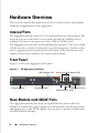
Front Panel
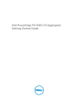
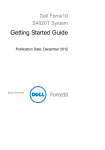
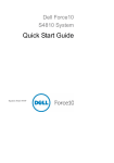
Figure 1-1 shows the Aggregator front panel:
Figure 1-1. I/O Aggregator Front Panel
USB Storage Port
Expansion Slot 1
Activity and Link Status LEDs
USB Console Port
Expansion Slot 0
40GbE QSFP+ Ports
Base Module with 40GbE Ports
The Aggregator provides two fixed 40-Gigabit Ethernet ports on the base
module. By default, these ports operate in 4x10GbE mode with breakout cables
and support up to eight 10GbE uplinks. You can also use the base-module ports
as 40GbE links for stacking.
8
Hardware Overview
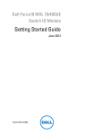
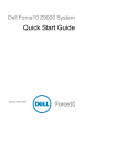
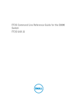
FlexIOTM Modules with Uplink Ports
On the Aggregator, FlexIO plug-in modules (Figure 1-2) operate only as
uplinks; stacking is not supported. The following modules are supported in
the two expansion slots:
•
4-Port 10-Gigabit Ethernet module using SFP+ optics or direct-attach
cables (1m, 3m, or 5m DAC)
4-Port 10GBASE-T module using RJ-45 connector (copper) cables
NOTE: Only one 4-Port 10GBASE-T module is supported in an Aggregator.
NOTE: The 10M speed is not supported on the 4-Port 10GBASE-T module. Only
100M, 1G, and 10G speeds are supported.
•
2-Port 40-Gigabit Ethernet QSFP+ (SR or direct attach only) module only
for 10GbE SFP+ connections using 4x10GbE breakout cables.
Figure 1-2. I/O Aggregator: FlexIO Modules
2-Port 40GbE QSFP+ Module
4-Port 10GbE SFP+ Module
4-Port 10GBASE-T Module (100Mb/1GbE/10GbE)
Hardware Overview
9
Use the FlexIO modules in an Aggregator that operates in standalone or
stacking mode:
•
In standalone mode, you can install any of the supported FlexIO modules
in two expansion slots. All ports operate at 10GbE to provide increased
bandwidth of up to 160Gbps for uplinks. Stacking is not supported.
•
In stacking mode, only the 40GbE ports on the base module are used for
stacking. FlexIO modules are required for uplink connections.
Usage Notes:
•
After you insert any FlexIO module into an empty slot, you must reload
the Aggregator for the module to be operational.
•
You can hot swap FlexIO modules of the same type without having to
reboot the Aggregator. If you insert a different type of plug-in module, you
must reload the Aggregator for the new module to be recognized.
•
All uplink ports are in the same 10GbE link aggregation group (LAG).
Tips for Aggregator standalone operation:
•
If you use 16 servers in an M1000e and you want a 2:1 oversubscription,
you only need to use the base module ports in 8x10GbE mode.
•
If you use 32 servers in an M1000e and you want a 2:1 oversubscription,
use the base-module ports in 8x10GbE mode and either a 2-Port 40GbE
QSFP+ module operating in 8x10GbE mode or two 4-Port 10GbE SFP+
modules. Use breakout cables with the 2-Port QSFP+ module.
Tips for Aggregator stacking operation:
•
To provide uplink connectivity for the stack, you must use at least one
FlexIO module in either expansion slot on any Aggregator in the stack.
•
To optimize redundancy and high availability, Dell Force10 recommends
that you use at least one FlexIO module for uplinks on each Aggregator in
a stack. If you do not use a FlexIO module on each stacked Aggregator for
uplink connectivity, in the event of a stack split, the server-facing ports on
Aggregators without an uplink connection are brought down.
All FlexIO modules, transceivers, and direct attach cables are sold separately.
10
Hardware Overview
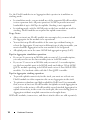
Port Numbering
When installed in a PowerEdge M1000e Enclosure, Aggregator ports are
numbered 1 to 56. Ports 1 to 32 are internal server-facing ports. Ports 33 to 56
are external ports numbered from the bottom to the top of the switch as
follows:
•
•
•
The 40GbE base-module ports operate:
•
In standalone 4x10GbE mode (default); ports are numbered 33 to 36
and 37 to 40.
•
In stacking mode; ports are numbered 33 and 37, and cannot be used
for uplinks.
The 2-Port 40-GbE QSFP+ module operates only in 4x10GbE mode:
•
In the bottom expansion slot, ports are numbered 41 to 44 and 45 to
48.
•
In the top expansion slot, ports are numbered 49 to 52 and 53 to 56.
4-Port 10-GbE SFP+ and 4-Port 10GBASE-T modules operate only in
4x10GbE mode:
•
In the bottom expansion slot, ports are numbered 41 to 44.
•
In the top expansion slot, ports are numbered 49 to 52.
To configure a port, you must specify the slot (0-5; default: 0) and port
number (1 to 56) in the interface port-type slot/port command, where slot is
the unit number of the Aggregator displayed in the show system brief
command; for example:
FTOS(conf)# interface tengigabitethernet 0/4
Hardware Overview
11
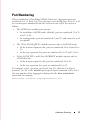
USB Console Port
Figure 1-3. USB Ports on Front Panel
USB Storage Port
USB Console Port
Use the lower USB console port (Figure 1-3) to manage the switch through an
RS-232 serial interface. This port provides a direct connection to the switch
and allows you to access the command-line interface (CLI) from a console
terminal connected to the port through the provided serial cable (with USB
type-A to female DB-9 connectors).
The console port supports asynchronous data of eight data bits, one stop bit,
no parity bit, and no flow control. The default baud rate is 9600 bps.
The upper USB port (Figure 1-3) functions as an external flash drive that you
can use to store configuration files, scripts, and so on.
12
Hardware Overview
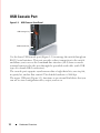
System and Port LEDs
The front panel of the Aggregator contains light emitting diodes (LEDs) that
provide information about the status of the switch (Figure 1-4).
Figure 1-4. System LEDs on Front Panel
Standalone 4x10GbE
Uplink Ports or
40GbE Stacking Ports
System Status LED
System Power LED
Table 1-1 describes system LED conditions.
Ta b l e 1 - 1 .
System LEDs
System LED
Color
Meaning
Green
Power is being supplied to the switch.
Off
The switch does not have power.
Blue
The switch is operating normally as a standalone
switch or as a stack master.
Off
The switch is not the stack master.
Amber
A fault has occurred, or the switch is booting.
Power
Status
Hardware Overview
13
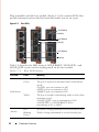
Plug-in modules and the base module (Figure 1-1) also contains LEDs that
provide information about the link status and traffic activity on a port.
Figure 1-5. Port LEDs
Link Status
Activity
Link Status
Activity
Link Status
Activity
Table 1-2 describes the LED status of 10GbE BASE-T, 10GbE SFP+, and
40GbE QSFP+ ports used in stacking mode on the base module.
Ta b l e 1 - 2 .
Port LED Status
Port LED
Color
Meaning
Off
The port is down.
Green
The port is up and can transmit traffic at maximum
speed:
A QSFP+ port can transmit at 40G.
An SFP+ port can transmit at 10G.
A BASE-T port can transmit at 10G.
Yellow
The port is up and is transmitting traffic at lower than
maximum speed:
A 40GbE QSFP+ port is transmitting at 10G.
A 10GbE SFP+ or 10GbE BASE-T port is
transmitting at 1G or 100M.
Off
No traffic is being transmitted or received on the port.
Blinking
Green
Traffic is being transmitted or received on the port.
Link Status
Activity
14
Hardware Overview
Table 1-3 describes the LED status of a 40GbE QSFP+ port that is split into
four 10GbE SFP+ ports using a 4x10GbE breakout cable.
Ta b l e 1 - 3 .
LED Status of 4x10GbE Port
Port LED
Color
Meaning
Off
All four 10GbE ports on a breakout cable are down.
Yellow
At least one of the four 10GbE ports on a breakout
cable is up.
Off
No traffic is being transmitted on any 10GbE port on
the breakout cable.
Blinking
Green
Traffic is being transmitted or received on at least one
of the 10GbE ports on the breakout cable.
Link Status
Activity
Installation
Site Preparation
Before installing the switch or switches, ensure that the chosen installation
location meets the following site requirements:
•
Clearance — There is adequate front and rear clearance for operator
access. Allow clearance for cabling, power connections, and ventilation.
•
Cabling — The cabling is routed to avoid sources of electrical noise such
as radio transmitters, broadcast amplifiers, power lines, and fluorescent
lighting fixtures.
•
Ambient Temperature — The ambient switch operating temperature
range is 10° to 40ºC (50° to 104ºF).
NOTE: Decrease the maximum temperature by 1°C (1.8°F) per 300 m (985 ft.)
above 900 m (2955 ft.).
•
Relative Humidity — The operating relative humidity is 8% to 85% (noncondensing) with a maximum humidity gradation of 10% per hour.
Hardware Overview
15
Unpacking the Aggregator
Package Contents
When unpacking each switch, ensure that the following items are included:
•
One PowerEdge M I/O Aggregator switch blade
•
One USB type A-to-DB-9 female cable
•
Getting Started Guide
•
Safety and Regulatory Information
•
Warranty and Support Information
•
Software License Agreement
Unpacking Steps
NOTE: Before unpacking the switch, inspect the container and immediately
report any evidence of damage.
1 Place the container on a clean, flat surface and cut all straps securing the
container.
2 Open the container or remove the container top.
3 Carefully remove the switch from the container and place it on a secure
and clean surface.
4 Remove all packing material.
5 Inspect the product and accessories for damage.
Installing and Configuring the
Aggregator
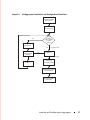
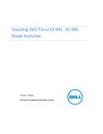
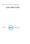
After you unpack the Aggregator, refer to the flow chart in Figure 1-6 for an
overview of the steps you must follow to install the blade and perform the
initial configuration.
16
Installing and Configuring the Aggregator
Figure 1-6. I/O Aggregator: Installation and Configuration Flow Chart
Insert Switch Blade
with FlexIO Modules
and Power On
Connect Console
Press
any key to
enter X-Loader
or U-Boot
menu?
Yes
X-Loader CLI
No
Run Memory Tests/
Configure Switch
Settings
Yes
U-Boot CLI
No
Reboot
Do not press a key
Do not press a key
Load Image
from Flash to RAM
(Optional) Reconfigure
Default Settings
(Optional) Assemble a
Switch Stack
Installing and Configuring the Aggregator
17
Installing the Aggregator in a PowerEdge Chassis
After you unpack the Aggregator, install FlexIO modules in the base module
and slide the Aggregator into one of the open I/O module slots in the back of
a PowerEdge M1000e chassis.
NOTE: If you plug a FlexIO module into an Aggregator that is already powered
on and inserted in an M1000e chassis, you must reboot the Aggregator for the plugin module to be activated.
The M1000e chassis is a 10U rack-mountable blade chassis that holds:
•
Server blades: Eight full-height or 16 half-height, or 32 quarter-height
blades
•
Switch blades: Six I/O modules and two integrated chassis management
controllers
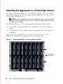
Server blades are installed in the front of the chassis (Figure 1-7); I/O
modules are installed in the back of the chassis (Figure 1-8).
Figure 1-7. PowerEdge M1000e: Front View with Server Blades
16 half-height
server blades
18
Installing and Configuring the Aggregator
Figure 1-8. PowerEdge M1000e: Back View with Six Aggregator Blades
CMC 2
CMC 1
Six I/O
Aggregator
blades
After you slide the Aggregator in so that the connectors on the back of the
blade are inserted into the chassis midplane, the switch receives power from
the chassis and automatically powers on. The chassis management controller
(CMC) in the chassis validates that the switch blade is a supported I/O
module before powering it on.
When the Aggregator powers on, the Boot loader loads the image in the local
flash. The image initializes the hardware and brings the switch up in
operational mode.
Installing and Configuring the Aggregator
19
Connecting a Console Terminal
After the I/O Aggregator powers on, complete all external cabling connections
and connect a terminal to the blade to configure the switch.
To monitor and configure the Aggregator using the serial console, use the
USB console port on the front panel of the switch ( Figure 1-3) to connect it
to a VT100 terminal or to a computer running VT100 terminal emulation
software. The console port is implemented as a data terminal equipment
(DTE) connector.
The following equipment is required to use the console port:
•
VT100-compatible terminal or a desktop or a portable computer with a
serial port running VT100 terminal emulation software, such as Microsoft
HyperTerminal.
•
A serial cable (provided) with a USB type-A connector for the console port
and DB-9 connector for the terminal.
Perform the following tasks to connect a terminal to the switch console port:
1 Connect the DB-9 connector on the serial cable to the terminal or
computer running VT100 terminal emulation software.
2 Configure the terminal emulation software as follows:
a
Select the appropriate serial port (for example, COM 1) to connect to
the console.
b
Set the data rate to 9600 baud.
c
Set the data format to 8 data bits, 1 stop bit, and no parity.
d
Set the flow control to none.
e
Set the terminal emulation mode to VT100.
f
Select Terminal keys for Function, Arrow, and Ctrl keys. Ensure that
the setting is for Terminal keys (not Microsoft Windows keys).
Connect the USB connector on the cable directly to the switch console port.
The console port on the Aggregator is located below the fixed 40GbE ports
(Figure 1-3).
20
Installing and Configuring the Aggregator
Invoking the X-Loader and U-Boot CLIs
During the boot process, you can perform various configuration tasks by
accessing the X-Loader and U-Boot CLIs, such as running memory tests
(X-Loader) and activating the backup image or recovering a password
(U-Boot).
You are first prompted to enter the X-Loader CLI by pressing any key when
the following message is displayed: Hit any key to stop autoboot.
If you do not press a key, the boot process continues and you are prompted to
enter the U-Boot CLI by pressing any key.
After performing any of the X-Loader or U-Boot tasks, the switch
automatically reboots when you exit a CLI. To continue with the boot process
without entering either CLI, do not press a key.
Reconfiguring Default Settings
The I/O Aggregator provides zero-touch configuration with:
•
default user name (root)
•
password (calvin)
•
VLAN (vlan1) and IP address for in-band management (DHCP)
•
IP address for out-of-band (OOB) management (DHCP)
•
read-only SNMP community name (public)
•
broadcast storm control (enabled)
•
IGMP multicast flooding (enabled)
•
VLAN configuration (all ports belong to all VLANs)
You can change any of these default settings using the CLI. You can change
many of the default settings using the CMC interface as described in
"Reconfiguration Using the CLI" on page 22.
Installing and Configuring the Aggregator
21
Before You Start
Before you reconfigure default settings, ensure that:
•
The Aggregator booted successfully when it powered on.
•
The console connection is established and the login prompt appears on the
screen of a VT100 terminal or terminal equivalent.
By default, the Aggregator receives the following IP addresses from a DHCP
server in the network. If you want to change the DHCP default setting, obtain
the required information from your network administrator, such as:
•
The IP address and subnet mask of the out-of-band interface used for
remote management via Telnet, SNMP, or other management agents.
•
The IP address and subnet mask of the default VLAN IP address used for
in-band management.
•
The IP address of the default gateway used for IP access to the Aggregator.
Reconfiguration Using the CMC Interface
For information about how to access the CMC to configure an Aggregator,
refer to the Dell Chassis Management Controller (CMC) User’s Guide on
the Dell Support website at
http://support.dell.com/support/edocs/systems/pem/en/index.htm. The CMC
online help provides information about how to use the Web interface. The
default settings that you can change using the CMC interface are noted in
the CLI reconfiguration procedure below.
Reconfiguration Using the CLI
To reconfigure any settings in the default Aggregator configuration using the
CLI:
1 (CMC-supported) From the console monitor or a remote management
session, log in by entering the user ID "root" and password "calvin". Then
press Enter.
Login: root
Password: *****
FTOS>
22
Installing and Configuring the Aggregator
2 At the EXEC mode prompt, enter enable. At the EXEC Privilege prompt,
enter configure to reach the configuration command mode.
FTOS> enable
FTOS# configure
FTOS(conf)#
3 (CLI only) At the configuration mode prompt, enter the hostname name
command to configure a hostname for the Aggregator, where name is a text
string of up to 20 alphanumeric characters.
Host names must start with a letter and end with a letter or number.
Characters within the string can be letters, numbers, and hyphens.
FTOS(conf)# hostname Aggregator1
FTOS(conf)#
4 (CMC-supported) To reconfigure the default username and password,
enter the username name password password command, where name is a
string of up to 63 alphanumeric characters and password is a string of up to
32 characters. Both values are case sensitive; spaces are supported.
FTOS(conf)# username admin password dellAgg1
FTOS(conf)#
5 (CLI only) At power up, the default VLAN for all ports is VLAN 1. To
reconfigure the default VLAN, enter the default vlan vlan-id command;
for example:
FTOS(conf)# default vlan 3
6 (CMC-supported) To reconfigure the SNMP community name used for
read-only management access to the switch, enter the snmp-server
community name ro command, where name is a text string of up to 20
alphanumeric characters and ro specifies read-only permission.
FTOS(conf)# snmp-server community dellSNMP ro
7 (CMC-supported) By default, the IP address and subnet mask of the outof-band management interface used for remote SNMP or Telnet access is
assigned by a DHCP server. You can reconfigure the default setting by
specifying an IP address with the following commands:
interface ManagementEthernet slot/port, where is slot is 0-1 and port is 0.
ip address ip-address/mask, where ip-address is in dotted-decimal format
(A.B.C.D) and mask is a subnet mask in /prefix-length format (/xx).
no shutdown enables the interface.
Installing and Configuring the Aggregator
23
For example:
FTOS(conf)# interface ManagementEthernet 1/0
FTOS(conf-if-ma-1/0)# ip address 128.0.0.1/24
FTOS(conf-if-ma-1/0)# no shutdown
8 (CMC-supported) To reconfigure the default route used by the out-ofband interface to access the Aggregator from a remote network, enter the
management route subnet/mask managementethernet command, where
subnet/mask is an IP address in dotted decimal format (A.B.C.D) and a
subnet mask that defines the out-of-band management network.
FTOS(conf)# management route 10.0.0.0/24
9 (CLI only) By default, the IP address of the default VLAN used to access
the switch from an in-band routing interface is assigned by a DHCP server.
You can reconfigure the default setting by specifying an IP address with the
ip address ip-address/mask command:
FTOS(conf)# interface vlan 1
FTOS(conf-if-vl-1)# ip address 10.1.1.4/24
10 (CLI only) To reconfigure the default route used by the in-band
management interface (default VLAN) used to access the Aggregator from
a remote network, enter the ip route subnet/mask vlan 1 command, where
subnet/mask is an IP address in dotted decimal format (A.B.C.D) and a
subnet mask that defines the in-band management network.
FTOS(conf)# ip route 10.1.1.0/24 vlan 1
11 (CLI only) By default, broadcast storm control is enabled on an Aggregator
to limit unregistered unicast, multicast, and broadcast packets. To disable
storm control, enter the following command:
FTOS(conf)# no io-aggregator broadcast storm-control
12 (CLI only) By default, IGMP multicast flooding is enabled on an
Aggregator. To disable multicast flooding to send unregistered multicast
packets only to interested hosts in a VLAN, enter the following command:
FTOS(conf)# no ip igmp snooping flood
24
Installing and Configuring the Aggregator
13 (CLI only) To verify the reconfigured settings, enter the show runningconfig command.
FTOS(conf)# show running-config
14 (CMC-supported) To save reconfigured settings to the startup
configuration, enter the write memory command.
FTOS(conf)# write memory
For more information about Aggregator configuration using the CLI, refer to
the Dell Force10 FTOS Configuration Guide for the PowerEdge M I/O
Aggregator.
Aggregator Auto-Configuration
After the Aggregator powers on, it auto-configures and is operational with
software features enabled, including:
•
VLANs: All ports are configured as members of all (4094) VLANs. All
VLANs are up and can send or receive layer 2 traffic. For more information,
refer to "Configuring VLANs" on page 27.
•
Data Center Bridging Capability Exchange Protocol (DCBX)
•
Fiber Channel over Ethernet (FCoE) connectivity
•
FCoE Initiation Protocol (FIP) snooping
•
Hybrid ports: Ports are administratively up and auto-configured to operate
as hybrid ports to transmit tagged and untagged VLAN traffic.
•
iSCSI optimization
•
IGMP snooping
•
Jumbo frames: Ports are set to a maximum MTU of 12,000 bytes by
default.
•
Link aggregation: All uplink ports are configured in a single LAG
(LAG 128).
•
Link Layer Discovery Protocol (LLDP): Enabled on all ports.
•
Link tracking: Enables server-facing links to be brought up only if the
uplink port-channel (LAG 128) is up.
Installing and Configuring the Aggregator
25
DCB Support
DCB enhancements for data center networks are supported to eliminate
packet loss and provision links with required bandwidth.
The Aggregator provides zero-touch configuration for DCB. The Aggregator
auto-configures DCBX port roles to match the DCBX configuration in the ToR
switches to which it connects through its uplink ports.
FCoE Connectivity
Many data centers use Fiber Channel (FC) in storage area networks (SANs).
Fiber Channel over Ethernet (FCoE) encapsulates Fiber Channel frames over
Ethernet networks.
On an Aggregator, the internal ports support FCoE connectivity and connect
to the converged network adapter (CNA) in blade servers. FCoE allows Fiber
Channel to use 10-Gigabit Ethernet networks while preserving the Fiber
Channel protocol.
The Aggregator also provides zero-touch configuration for FCoE configuration.
The Aggregator auto-configures to match the FCoE settings used in the ToR
switches to which it connects through its uplink ports.
iSCSI Operation
Support for iSCSI traffic is turned on by default when the Aggregator powers
up. No configuration is required.
When the Aggregator powers up, it monitors known TCP ports for iSCSI
storage devices on all interfaces. When a session is detected, an entry is
created and monitored as long as the session is active.
The Aggregator also detects iSCSI storage devices on all interfaces and autoconfigures to optimize performance. Performance optimization operations,
such as Jumbo frame size support, STP port-state fast, and disabling of storm
control on interfaces connected to an iSCSI storage device, are applied
automatically.
CLI configuration is necessary only when the configuration includes iSCSI
storage devices that cannot be automatically detected and when non-default
QoS handling is required.
26
Installing and Configuring the Aggregator
Link Aggregation
All uplink ports are configured in a single LAG (LAG 128). Server-facing ports
are auto-configured as part of link aggregation groups if the corresponding
server is configured for LACP-based NIC teaming. Static LAGs are not
supported.
Tip: The recommended LACP timeout is long-timeout mode.
Link Tracking
By default, all server-facing ports are tracked by the operational status of the
uplink LAG. If the uplink LAG goes down, the Aggregator loses its
connectivity and is no longer operational; all server-facing ports are brought
down.
Tip: If installed servers do not have connectivity to a ToR switch, check the
Link Status LED of uplink ports on the Aggregator. If all LEDs are on, check
the LACP configuration on the ToR switch that is connected to the
Aggregator to ensure the LACP is correctly configured.
Configuring VLANs
By default, all Aggregator ports belong to all 4094 VLANs and are members of
untagged VLAN 1. You can use the CLI or CMC interface to configure only
the required VLANs on a port.
When you configure VLANs on server-facing interfaces (ports 1 to 32), you
can assign VLANs to a port or a range of ports by entering the vlan tagged or
vlan untagged commands in interface configuration mode; for example:
FTOS(conf)# interface tengigabitethernet 0/2 - 4
FTOS(conf-if-range-te-0/2-4)# vlan tagged 5,7,10-12
FTOS(conf-if-range-te-0/2-4)# vlan untagged 3
You can also use the CMC interface to configure VLANs. For information
about how to access the CMC, refer to the Dell PowerEdge M1000e
Enclosure Hardware Owner's Manual or Dell Chassis Management
Controller (CMC) User’s Guide on the Dell Support website at
http://support.dell.com/support/edocs/systems/pem/en/index.htm The CMC
online help provides information about how to use the Web interface.
Installing and Configuring the Aggregator
27
Uplink LAG
The tagged VLAN membership of the uplink LAG is automatically
configured based on the VLAN configuration of all server-facing ports (ports 1
to 32).
The untagged VLAN used for the uplink LAG is always the default VLAN.
Server-Facing LAGs
The tagged VLAN membership of a server-facing LAG is automatically
configured based on the server-facing ports that are members of the LAG.
The untagged VLAN of a server-facing LAG is configured based on the
untagged VLAN to which the lowest numbered server-facing port in the LAG
belongs.
Tip: Dell Force10 recommends that you configure the same VLAN
membership on all LAG member ports.
Stacking Mode
When you configure an Aggregator to operate in stacking mode
("Configuring and Bringing Up a Stack" on page 31), VLANs are reconfigured
as follows:
•
If an Aggregator port belonged to all 4094 VLANs in standalone mode
(default), all VLAN membership is removed and the port is assigned only
to default VLAN 1. You must configure additional VLAN membership as
necessary.
•
If you had manually configured an Aggregator port to belong to one or
more VLANs (non-default) in standalone mode, the VLAN configuration
is retained in stacking mode only on the master switch.
When you reconfigure an Aggregator from stacking to standalone mode:
•
Aggregator ports that you manually configured for VLAN membership in
stacking mode retain their VLAN configuration in standalone mode.
•
To restore the default auto-VLAN mode of operation (in which all ports are
members of all 4094 VLANs) on a port, enter the auto vlan command; for
example:
FTOS(conf)# interface tengigabitethernet 0/2
FTOS(conf-if-te-0/2)# auto vlan
28
Installing and Configuring the Aggregator
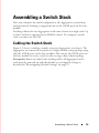
Assembling a Switch Stack
After you complete the initial configuration, the Aggregator is powered up
and operational. Stacking is supported only on the 40GbE ports on the base
module.
Stacking is limited to two Aggregators in the same chassis in a single stack. Up
to three stacks are supported in an M1000e chassis. To configure a switch
stack, you must use the CLI.
Cabling the Switch Stack
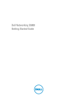
Figure 1-9 shows a stacking example using two Aggregators in a chassis. The
Aggregators are connected to operate as a single stack in a ring topology using
only the 40GbE ports on the base modules. You can use the 40GbE ports on
the base module to create a stack in either a ring or daisy-chain topology.
Prerequisite: Before you attach the stacking cables, all Aggregators in the
stack must be powered up with the default or reconfigured settings as
described in "Reconfiguring Default Settings" on page 21.
Assembling a Switch Stack
29
Figure 1-9. Switch Stack Using 40GbE Ports on Two Aggregators
Use only QSFP transceivers and QSFP cables (separately purchased) to
connect stacking ports; for example:
1 Insert a QSFP cable in the bottom base-module port on the rightmost
Aggregator.
2 Connect the cable to the bottom base-module port on the next Aggregator
to the left.
3 On the leftmost Aggregator, connect the top base-module port to the top
base-module port on the rightmost Aggregator to create a loop.
NOTE: The resulting topology allows the stack to function as a single switch with
resilient fail-over capabilities.
30
Assembling a Switch Stack
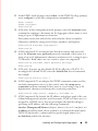
Configuring and Bringing Up a Stack
After you attach the cables in a stack of Aggregators, follow these steps to
configure and bring up the stack:
1 Connect the terminal to the console port on an Aggregator. Enter the
following commands to access the CLI and configure the base-module
ports for stacking mode:
Login: username
Password: *****
FTOS> enable
FTOS# configure
FTOS(conf)# stack-unit 0 iom-mode stack
Where stack-unit 0 defines the default stack-unit number in the initial
configuration of a switch.
2 Save the stacking configuration on the 40GbE ports:
FTOS# write memory
3 Repeat Steps 1 and 2 on each Aggregator in the stack by entering the
stack-unit 0 iom-mode stack command and saving the configuration.
4 Reboot each Aggregator by entering the reload command in EXEC
Privilege mode:
FTOS# reload
If the stacked switches all reboot at approximately the same time, the
Aggregator with the highest MAC address is automatically elected as the
master switch. The Aggregator with the next highest MAC address is
elected as standby master.
Tip: You can ensure that a stacked switch becomes the master by rebooting
the switch first, and waiting for it to come up before rebooting the second
switch in the stack.
The Status LED on the Aggregator that is elected as the master switch is
blue. Perform VLAN and other software configuration for the stack by
connecting to the console port on the master unit.
To determine which switch is the stack master, you can also enter the show
system command at the terminal.
Assembling a Switch Stack
31
To remove an Aggregator from the stack, enter the stack-unit 0 iom-mode
standalone command in global configuration mode. After entering the
command, save the configuration and reload the Aggregator for the change to
take effect.
Managing a Stack
Master and Member Switches
You can manage a stack of Aggregators as a single entity when they are
connected together. Manage the stack from the CLI through the serial
console connection or a remote Telnet session over the OOB management IP
address.
When a stack is created, one switch automatically becomes the master switch
and another switch is elected standby master. The master switch maintains
stack operation with minimal impact in the event of:
•
Switch failure
•
Inter-switch stacking link failure
•
Switch insertion
•
Switch removal
If the master switch goes off line, the standby master replaces it as the new
master.
Stack Startup
Topology Discovery
When a stack is formed, a topology discovery process builds up a database
that contains information about both switches in the stack, including the
FTOS version, hardware version, management priority, and switch MAC
address. Use the CLI (show system command) to view this information.
Auto Stack Number Assignment
During the stack formation process, a unique stack-unit number is assigned if
the same number is assigned to more than one switch. After assignment is
complete, each switch saves its stack-unit number. To view stack-unit
numbers, enter the show system command.
32
Assembling a Switch Stack
FTOS Version Checking
Following the stack-unit number assignment, the master switch performs a
consistency check to ensure both switches in the stack are running the same
FTOS version.
If the master switch determines that both switches are not running the same
FTOS version, the ports on the non-master switch with the incorrect version
are disabled.
To download the required FTOS image from the master switch and reload a
member switch so that it joins the stack, enter the following command in
EXEC Privilege mode:
FTOS# upgrade system stack-unit unit-number partition
Where stack-unit unit-number identifies the switch whose FTOS version
needs to be upgraded; partition identifies the partition on the master switch
from which the FTOS image boots up. For example:
FTOS# upgrade system stack-unit 3 a:
To display the boot partition used on the master switch, enter the show
version command.
To ensure that a stack unit boots from partition a:, enter the commands:
FTOS# configure
FTOS(conf)# boot system stack-unit unit-number primary system
a:
FTOS(conf)# end
FTOS# write memory
FTOS# power-cycle stack-unit unit-number
NOTE: When an Aggregator is stacked, booting is supported only from flash
memory; it is not supported over the network using an IP address.
System Initialization
The master switch initializes the stack using the last saved system
configuration file.
If you change the stack configuration, be sure to save the configuration file.
The master switch automatically distributes the configuration file to the
standby master switch.
In case of a split stack in which the master switch and standby master become
disconnected, the last saved configuration is used on both switches. The two
switches now operate as two separate stacks, each consisting of one switch.
Assembling a Switch Stack
33
Next Steps
•
You can customize the Aggregator for use in your data center network as
necessary. To perform additional switch configuration, do one of the
following:
•
For remote out-of-band management, enter the OOB management
interface IP address into a Telnet or SSH client and log in to the
switch using the user ID and password to access the CLI.
•
For local management using the CLI, use the attached console
connection.
•
For remote in-band management from a network management
station, enter the VLAN IP address of the management port and log in
to the switch to access the CLI.
•
If you installed the Aggregator in a stack, you can configure additional
settings for switch stacking.
•
In case of an FTOS upgrade, you can check to see that an Aggregator is
running the latest FTOS version by entering the show version command.
To download an FTOS version, go to http://support.dell.com.
For information about how to configure software features, refer to the User’s
Configuration Guide for the PowerEdge M I/O Aggregator on the Dell Support
website at http://support.dell.com/manuals.
34
Next Steps
Technical Specifications
The Aggregator is an I/O module and installed with the Server (model:
PowerEdge M1000e) for communication.
CAUTION: Lithium Battery Caution: There is a danger of explosion if the battery
is incorrectly replaced.
Replace batteries only with same or equivalent type. Dispose of the batteries
according to the manufacturer's instructions.
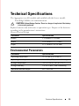
Chassis Physical Design
Parameter
Specifications
Height
1.32 inches (33.45 mm)
Width
10.81 inches (274.75 mm)
Depth
12.17 inches (309.24 mm)
Environmental Parameters
Parameter
Specifications
Operating temperature
32° to 104°F (0° to 40°C)
Operating humidity
10 to 85% (RH), non-condensing
Storage temperature
–40° to 158°F (–40° to 70°C)
Storage humidity
5 to 95% (RH), non-condensing
Maximum thermal output
419.7 BTU/hr
Technical Specifications
35
Power Requirements
Parameter
Specifications
Power supply
100–240 VAC 50/60 Hz
Maximum current draw per system
2 A @ 100/120 VAC
1 A @ 200/40 VAC
Maximum power consumption
123 Watts
Reliability
MTBF 355,178 hours
IEEE Standards
The Aggregator complies with the following IEEE standards:
36
•
802.1AB LLDP
•
802.1p L2 Prioritization
•
802.1Q VLAN Tagging
•
802.3ab Gigabit Ethernet (1000BASE-T)
•
802.3ac Frame Extensions for VLAN Tagging
•
802.3ad Link Aggregation with LACP
•
802.3ae 10 Gigabit Ethernet (10GBASE-X)
•
802.3ap 10GbE-KR
•
802.3u Fast Ethernet (100BASE-TX)
•
802.3x Flow Control
•
802.3z Gigabit Ethernet (1000BASE-X)
•
MTU 12K bytes
Technical Specifications
Printed in the U.S.A.
ww w.d el l .c o m | s up p or t . de l l. c o m