1
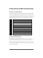
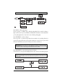
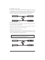
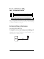
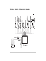
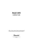
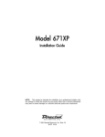
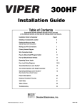
3200HS
Installation Guide
NOTE: This product is intended for installation by a professional installer only!
Any attempt to install this product by any person other than a trained professional
may result in severe damage to a vehicle’s electrical system and components.
© 2002 Directed Electronics, Inc. Vista, CA
N416S 12-02
The Bitwriter® (p/n 998T)
requires chip version 1.4 or
newer to program this unit.
Bitwriter™, Code Hopping™, DEI®, Doubleguard®, ESP™, FailSafe®, Ghost Switch™, Learn
Routine™, Nite-Lite®, Nuisance Prevention® Circuitry, NPC®, Revenger®, Silent Mode™,
Soft Chirp®, Stinger®, Valet®, Vehicle Recovery System®, VRS®, and Warn Away® are all
Trademarks or Registered Trademarks of Directed Electronics, Inc.
www.directechs.com
DirectFax 800-999-1329 Technical Support 800-753-0800
These resources are for authorized Directed Dealer use only.
Table of Contents
Primary Harness (H1) Wire Connection Guide . . . . . . . . . . . . . . . . . . . . . . . . . . . . . . . . . . . .4
Primary Harness (H1) Wiring Diagram . . . . . . . . . . . . . . . . . . . . . . . . . . . . . . . . . . . . . . . .4
Primary Harness Wire Descriptions . . . . . . . . . . . . . . . . . . . . . . . . . . . . . . . . . . . . . . . . . . .4
Door Lock Harness (H4), Wire Connection Guide . . . . . . . . . . . . . . . . . . . . . . . . . . . . . . . . .8
Peripheral Plug-In Harnesses . . . . . . . . . . . . . . . . . . . . . . . . . . . . . . . . . . . . . . . . . . . . . . . . . .8
Super Bright LED, 2-Pin WHITE Plug . . . . . . . . . . . . . . . . . . . . . . . . . . . . . . . . . . . . . . . .8
Valet/Program Switch, 2-Pin BLUE Plug . . . . . . . . . . . . . . . . . . . . . . . . . . . . . . . . . . . . . . .9
Programmer Interface, 3-Pin Port . . . . . . . . . . . . . . . . . . . . . . . . . . . . . . . . . . . . . . . . . . . . .9
System Features Learn Routine . . . . . . . . . . . . . . . . . . . . . . . . . . . . . . . . . . . . . . . . . . . . . . . . .9
System Features Menus . . . . . . . . . . . . . . . . . . . . . . . . . . . . . . . . . . . . . . . . . . . . . . . . . . . . . . .11
Feature Descriptions . . . . . . . . . . . . . . . . . . . . . . . . . . . . . . . . . . . . . . . . . . . . . . . . . . . . . . . . .11
Transmitter/Receiver Learn Routine . . . . . . . . . . . . . . . . . . . . . . . . . . . . . . . . . . . . . . . . . . . . .13
Transmitter Configurations . . . . . . . . . . . . . . . . . . . . . . . . . . . . . . . . . . . . . . . . . . . . . . . . . . .15
Standard Configuration . . . . . . . . . . . . . . . . . . . . . . . . . . . . . . . . . . . . . . . . . . . . . . . . . . . .15
Single Button Arm/Disarm Configuration . . . . . . . . . . . . . . . . . . . . . . . . . . . . . . . . . . . . . .15
Rapid Resume Logic . . . . . . . . . . . . . . . . . . . . . . . . . . . . . . . . . . . . . . . . . . . . . . . . . . . . . . . . .15
Wiring Quick Reference Guide . . . . . . . . . . . . . . . . . . . . . . . . . . . . . . . . . . . . . . . . . . . . . . . . .16
©
2002 Directed Electronics, Inc.
3
Primary Harness (H1) Wire Connection Guide
Primary Harness (H1) Wiring Diagram
The primary harness supplied with this unit is the standard 12-pin harness used by Directed security
systems. Two wires in the plug are not used. The upgrade from this unit to a security system would
simply require unplugging and exchanging control units and connecting the necessary wires to the
vehicle. The functions of all the wires that are used in the primary harness are outlined in the
following wiring diagram and the wire connections are described in the wire connection guides.
H1/1
___ ORANGE
H1/2
___ WHITE
H1/3
___ WHITE/BLUE
H1/4
___ BLACK/WHITE
H1/5
___ GREEN
H1/6
___ BLUE
H1/7
___ VIOLET
No Function
H1/8
___ BLACK
(-) Chassis Ground Input
H1/9
___ YELLOW
H1/10
___ BROWN
H1/11
___ RED
H1/12
___ RED/WHITE
(-) 500 mA Armed Output
(-) Light Flash Output
(-) 200 mA Channel 3 Validity Output
(-) 200 mA Domelight Supervision Output
No Function
(-) 200 mA Second Unlock Output
Switched Ignition Input
(-) Horn Honk Output
(+) Constant Power Input
(-) 200 mA Channel 2 Validity Output
Primary Harness Wire Descriptions
H1/1 ORANGE (-) Ground-When-Armed Output
This wire supplies a (-) 500 mA ground as long as the system is armed. This output ceases as soon
as the system is disarmed. The orange wire is pre-wired to control the 8618 starter kill relay.
NOTE: if using the H1/1 Orange wire to activate an add-on accessory such as window automation,
pager or voice module a 1Amp diode must be installed to ensure proper operation. Insert the diode
as shown in the following diagram.
4
©
2002 Directed Electronics, Inc.
IMPORTANT! Never interrupt any wire other than the starter wire.
H1/2 WHITE (-) Parking Light Output
This wire provides a (-) 200mA output to flash the parking lights. This is suitable for driving (-)
light control wires in Toyota, Lexus, BMW, some Mitsubishi, some Mazda, etc. If the vehicle has a
positive parking light circuit, a relay must be used to flash the parking lights.
H1/3 WHITE/BLUE (-) Channel 3 Output
This wire provides a (-) 200 mA output whenever the transmitter code controlling Channel 3 is
received. This output will continue as long as that transmission is received. Use for options such as
DEI’s 551T Valet® Start system, 529T or 530T power window controllers, etc.
IMPORTANT! Never use this wire to drive anything but a relay or a low-current input!
The transistorized output can only provide 200 mA of current, and connecting directly
to a solenoid, motor, or other high-current device will cause it to fail.
H1/4 BLACK/WHITE (-) 200 mA Domelight Supervision Output
Connect this wire to the optional domelight supervision relay as shown in the following diagram:
IMPORTANT! This output is only intended to drive a relay. It cannot be connected
directly to the domelight circuit, as the output cannot support the current draw of one
or more bulbs.
©
2002 Directed Electronics, Inc.
5
H1/6 BLUE (-) 200 mA Second Unlock Output
The H1/6 BLUE output is used for progressive unlock. A progressive unlock system unlocks the
driver's door when the unlock (disarm) button is pressed and unlocks the passenger doors if the
unlock (disarm) button is pressed again within 15 seconds after unlocking the driver's door. The
BLUE wire outputs a low current (-) pulse on the second press of the unlock button of the transmitter. This negative unlock output is used to unlock the passenger doors.
H1/8 BLACK (-) Chassis Ground Connection
Connect this wire to a clean, paint-free sheet metal location (driver kick panel) using a factory bolt
that DOES NOT have any vehicle component grounds attached to it. A screw should only be used
when in conjunction with a two-sided lock washer. Under dash brackets and door sheet metal are
not acceptable ground points. It is recommended that all security components be grounded at the
same location.
H1/9 YELLOW (+) Ignition Input
Connect this wire to an ignition source. This input must show (+)12V with the key in run position
and during cranking. Make sure that this wire cannot be shorted to the chassis at any point. This
wire will trigger the system if the ignition is turned on before the unit is disarmed (doors unlocked
with the remote). It will also honk the vehicle’s horn and flash the parking lights (if connected).
6
©
2002 Directed Electronics, Inc.
H1/10 BROWN (-) Horn Honk Output
This wire supplies a (-) 200 mA output that can be used to honk the vehicle horn. It outputs a single
pulse when locking the doors with the remote, and two pulses when unlocking with the remote. This
wire will also output pulses for 30 seconds when the Panic Mode is activated. If the vehicle has a (+)
horn circuit, an optional relay can be used to interface with the system, as shown below.
H1/11 RED (+)12V constant power input
Before connecting this wire, remove the supplied fuse. Connect to the battery positive terminal or
the constant 12V supply to the ignition switch.
NOTE: Always use a fuse within 12 inches of the point you obtain (+)12V. Do not use the fuse in
the harness for this purpose. This fuse protects the module itself.
H1/12 Red/white channel 2, 200mA (-) output
When the system receives the transmitter code controlling Channel 2 for longer than 1.5 seconds,
the red/white wire will supply an output as long as the transmission continues. This is often used
to operate a trunk/hatch release or other relay-driven functions.
IMPORTANT! Never use this wire to drive anything but a relay or a low-current input!
The transistorized output can only supply 200 mA of current. Connecting directly to a
solenoid, motor, or other high-current device will cause it to fail.
©
2002 Directed Electronics, Inc.
7
Door Lock Harness (H4),
Wire Connection Guide
H4/A
___ Green
(-) Lock, (+) Unlock Output
H4/B
___ Empty
Unless Using 451M
H4/C
___ Blue
(-) Unlock, (+) Lock Output
IMPORTANT! The door lock outputs are low current and should not be attached
directly to any high current device; they are only to be used to activate relays
NOTE: For detailed instructions about connecting to the vehicle’s power door lock systems, refer
to the Door Lock Wiring guide (Document No. 1041) available only to authorized dealers though
the technical resources listed at the front of this guide.
Peripheral Plug-In Harnesses
Super Bright LED, 2-Pin WHITE Plug
The super bright LED operates at (+) 2 volt DC and plugs into the two-pin WHITE port. Make
sure the LED wires are not shorted to ground as the LED will be damaged. Multiple LED’s can be
used, but they must be wired in series. The LED fits into a 9/32-inch mounting hole. Be sure to
check for clearance prior to drilling the mounting hole.
DIA-41
8
©
2002 Directed Electronics, Inc.
Valet/Program Switch, 2-Pin BLUE Plug
The Valet/Program button should be accessible from the driver’s seat. It plugs into the BLUE port
on the side of the unit. Consider how the button will be used before choosing a mounting location.
Check for rear clearance before drilling a 9/32-inch hole and mounting the button.
Programmer Interface, 3-Pin Port
The BLACK three-pin port is provided for programming of the unit. When using the 998T
Bitwriter, it is possible to configure any and all of the programmable functions. For more information please refer to the guide packaged with the programmer.
System Features Learn Routine
The System Features Learn Routine dictates how the unit operates. It is possible to access and
change any of the feature settings using the Valet/Program switch. However, this process can be
greatly simplified by using the 998T Bitwriter. Any of the settings can be changed and then assigned
to a particular transmitter, up to four, a feature called Owner Recognition. Each time that particular
transmitter is used to disarm the system, the assigned feature settings will be recalled. Owner
Recognition is only possible when programming the unit via the 998T Bitwriter.
If the system was previously programmed using the 998T Bitwriter, the learn routine may be
locked. If the horn generates one long honk when attempting to program the unit, the learn routine
is locked and must be unlocked using the 998T Bitwriter before proceeding.
©
2002 Directed Electronics, Inc.
9
To program the learn routine:
1.
Key. Turn the ignition on and then back off.
2.
Choose. Within 10 seconds, press and release the Valet®/Program switch
the number of times corresponding to the feature number you want to
program. (See Feature Menus.) Once the Valet®/Program switch has
been pressed and released the desired number of times, press it once more
and hold it. After a second, the LED will flash and the horn will honk to
indicate which feature you have accessed.
3.
Transmit. The transmitter is used to select the desired setting. As shipped,
the unit is configured to the LED ON settings. These are the default
settings. Pressing the lock button will set it to the LED ON setting. The
LED will light solid (stop flashing) to indicate the setting. The horn will
honk once (if connected). Pressing the unlock button will change the
setting to the LED OFF setting. The LED will go out indicating the
change and the horn will honk twice (if connected).
4.
Release. The Valet®/Program switch can now be released.
For example, to program the arming mode from active to passive, within 10 seconds of turning the
ignition off, and press and release the Valet/Program switch once. Then press it again and hold it.
The LED will flash in groups of one and the horn will honk once (if connected). While holding the
Valet®/Program switch, press the unlock button. The LED will stop flashing and go out. The horn
will honk twice if connected. Passive arming is now programmed. If that was not the desired setting,
without releasing the Valet®/Program switch, press the lock button. The LED will light solid and
the horn will honk once if connected. Active arming is now programmed. Release the
Valet®/Program switch after the selection has been made.
You can advance from feature to feature by pressing and releasing the Valet®/Program switch the
number of times necessary to get from the feature you just programmed to the feature you wish to
access. For example, if you just programmed Feature 2 and you next want to program Feature 3 to
off, release the Valet/Program switch. Press and release it once to advance from Feature 2 to Feature
3. Then press it once more and hold it. The LED will flash in groups of three and the horn will
honk three times (if connected) to confirm that you have accessed Feature 3.
10
©
2002 Directed Electronics, Inc.
The learn routine will be exited if:
➤ The ignition is turned on.
➤ The Valet/Program switch is pressed too many times.
➤ More than 15 seconds elapses between programming steps.
One long horn honk (if connected) indicates that the Learn Routine has been exited.
System Features Menus
Feature
Number
Default LED ON Setting
(Press Channel 1)
LED OFF Setting
(Press Channel 2)
1
Active arming
Passive arming
2
Chirps ON
Chirps OFF
3
Ignition-controlled door lock ON
Ignition-controlled door lock OFF
4
Ignition-controlled door unlock ON
Ignition-controlled door unlock OFF
5
Active locking
Passive locking
6
Ignition-controlled domelight ON
Ignition-controlled domelight OFF
7
0.8 second door lock pulses
3.5 second door lock pulses
8
Double pulse unlock OFF
Double pulse unlock ON
9
Security features ON
Security features OFF
10
Code Hopping ON
Code Hopping OFF
Feature Descriptions
The features of the system are described below. Features that have additional settings that can be
selected only when programming with the 998T Bitwriter are indicated by the following
icon:
1 ACTIVE/PASSIVE ARMING: When active arming is selected, the starter kill will arm (if
connected) only when the transmitter is used. When set to passive arming, the starter kill will arm
(if connected) 30 seconds after the ignition key is turned off.
2 CHIRPS ON/OFF: This feature controls the chirps that confirm arming and disarming of the
system. A siren or horn must be connected to the H1/10 BROWN wire.
©
2002 Directed Electronics, Inc.
11
3 IGNITION CONTROLLED DOOR LOCK ON/OFF: When turned on, the doors will lock three
seconds after the ignition is turned on.
4 IGNITION CONTROLLED DOOR UNLOCK ON/OFF: When turned on, the doors will
unlock when the ignition is turned off.
5 ACTIVE/PASSIVE LOCKING: If passive arming is selected in Feature 1, then the system can be
programmed to either lock the doors when passive arming occurs, or only lock the doors when the
system is armed with a transmitter. Active locking means the doors will not lock when the system
passively arms. Passive locking means that the doors will lock whenever the system passively arms
the starter kill (if connected).
6 IGNITION CONTROLLED DOMELIGHT: If turned on, the system will turn on the domelight
for 30 seconds when the ignition is turned off. The domelight supervision output (H1/4) wire must
be connected to an optional relay as described in the Primary Harness Wire Connection Guide.
7 DOOR LOCK PULSE DURATION: Some European vehicles, such as Mercedes-Benz and Audi,
require longer lock and unlock pulses to operate the vacuum pump. Programming the system to
provide 3.5 second pulses will accommodate the door lock interface in these vehicles. The default
setting is 0.8 second door lock pulses.
8 DOUBLE PULSE UNLOCK OFF/ON: Some vehicles require two pulses on a single wire to
unlock the doors. When the double pulse unlock feature is turned on, the BLUE H4/C wire will
supply two negative pulses instead of a single pulse. At the same time, the GREEN H4/A wire will
supply two positive pulses instead of a single pulse. This makes it possible to directly interface with
double pulse vehicles without any extra parts.
9 SECURITY FEATURES ON/OFF: In the ON setting the (-) ground-when-armed output will be
active and can be used to operate starter kill. The unit will also trigger a panic sequence if the
ignition is turned on before disarming the system. Turning the security features off will turn off both
the starter kill feature and the triggered sequence with ignition.
10 CODE-HOPPING ON/OFF: The system features Code-Hopping as an option. To use CodeHopping technology, this feature must be programmed on.
12
©
2002 Directed Electronics, Inc.
Transmitter/Receiver Learn Routine
The system comes with two transmitters that have been taught to the receiver. The receiver can store
up to four different transmitter codes in memory. Use the following learn routine to add transmitters to the system or to change button assignments if desired.
If the system was previously programmed using the 998T Bitwriter, the learn routine may be locked.
If the horn generates one long honk when attempting to program the unit, the learn routine is locked
and must be unlocked using the 998T Bitwriter before proceeding.
1.
Key. Turn the key to the ON position.
2.
Choose. Within 10 seconds, press and release the Valet/program switch
the number of times corresponding to the desired channel listed below.
Once you have selected the channel, press the switch once more and
HOLD it. The LED will flash and the horn will honk ( if connected) to
confirm the selected channel. Do not release the Valet/program switch.
3.
Transmit. While holding the Valet/Program button, press the button
from the transmitter that you wish to assign to the selected channel. The
unit will chirp indicating successful programming. It is not possible to
teach a transmitter button to the system more than once.
4.
Release. Once the code is learned, the Valet/Program button can be
released.
Channel Number
Function
Wire Color
1
Arm/Disarm/Panic
2
Silent Mode/Remote Valet/Trunk Release
RED/WHITE
3
Remote Start or Other Accessory
WHITE/BLUE
4
Arm only
5
Disarm only
6
Panic only
7
Auto-learn Standard Configuration*
8
Auto-learn Single Button Arm/Disarm Configuration*
9
Delete all transmitters
**NOTE: For Auto Learn Configurations, see Transmitter Configurations section of this guide.
©
2002 Directed Electronics, Inc.
13
Channels #4-6: Channels 4 through 6 are used to assign the arm, disarm and panic functions to
separate buttons on the remote control. Teaching a button to Channel 4 erases all information about
that remote from memory. Any auxiliary functions that are desired will have to be reprogrammed.
Similarly, if the remote is set up to use the separate arm, disarm and panic channels and a button
from that remote is entered into channel one, the remote will be erased from memory, and the system
will only recognize the button that was entered into Channel 1.
Channel #9: If any button from a known transmitter is programmed to Channel 9, all transmitters
will be erased from memory and the system features will revert to the default settings. This is useful
in cases where the one of the customer's transmitters is lost or stolen. This will erase any lost or
stolen transmitters from the system's memory. It can also be used to start from scratch if the transmitter buttons were programmed incorrectly.
To exit the learn routine:
One long horn honk indicates that Learn Routine has been exited.
➤
➤
➤
14
Ignition is turned off.
Valet/Program button is pressed too many times.
More than 15 seconds elapse between steps.
©
2002 Directed Electronics, Inc.
Transmitter Configurations
The transmitters can be programmed with the standard or single button arm/disarm configurations
by using the Auto Learn functions in the Transmitter/Receiver Learn Routine.
Standard Configuration
A remote that uses the standard configuration operates similarly to many factory keyless entry
remotes. A standard configuration transmitter allows arming, disarming, and Panic Mode activation
with separate buttons. When programmed for standard configuration using the Channel 7 Autolearn configuration, the transmitter buttons are assigned to the following functions:
and
operates
Arm only
operates
Disarm only
operates
Channel 2 and Silent Mode
operates
Panic only
operate
Channel 3
Single Button Arm/Disarm Configuration
When programmed for single button arm/disarm configuration using the Channel 8 Auto-learn
configuration, the transmitter buttons are assigned to the following functions:
and
operates
Arm/Disarm/Panic
operates
Channel 2 and Silent Mode
operate
Channel 3
Rapid Resume Logic
Rapid Resume Logic ensures that the when the system is powered up it will return to the same state
it was in when power is disconnected. For a full description of Rapid Resume Logic refer to the
owner's manual.
©
2002 Directed Electronics, Inc.
15
Wiring Quick Reference Guide
16
©
2002 Directed Electronics, Inc.