1
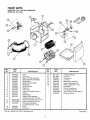
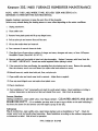
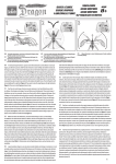
Kenmore
1700
11 GALLON
CENTRAL HUMIDIFIER
Installation
Maintenance
Repair Parts
Troubleshooting
Sears, Roebuck and Co., Hoffman Estates, IL 60179 U.S.A.
contents
WARRANTY ...........................................
2
BEFORE YOU START
Rules for Safe Installation
and Operation ...................................
2
Tools and Materials Needed .................. 2
UNDERSTANDING HUMIDITY ..............
SELECTING A LOCATION .....................
DISASSEMBLY/CONVERSION
.............
INSTALLATION ......................................
WATER SUPPLY ...................................
3
4
4
5
6
HUMIDISTAT ..........................................
OPERATION ..........................................
MAINTENANCE .....................................
SERVICE HINTS ..................................
REPAIR PARTS ....................................
8
9
9
10
11
introduction
Please read the instructions before you install and use your humidifier. This will help you obtain the full value from the humidifier. It will
also help you avoid any needless service cost, if the problem is something we cannot control and cannot cover in our Warranty.
FULL ONE YEAR WARRANTY ON HUMIDIFIER
If, within one year from the date of purchase, this humidifier fails due to a defect in material or workmanship,
repair it, free of charge.
WARRANTY
SERVICE IS AVAILABLE
CENTER IN THE UNITED STATES.
BY SIMPLY
CONTACTING
THE
NEAREST
SEARS
STORE
Sears will
OR SERVICE
This warranty gives you specific legal rights, and you may also have other rights which vary from state to state.
This warranty DOES NOT cover the replacement
media pad.
Sears, Roebuck and Co,, Dept, 817WA, Hoffman Estates, IL 60179
DO-IT-YOURSELF
CHECK LIST
If you feel the following operations are within your skills, you should
have no difficulty installing this humidifier.
I
You must realize that the wrong use of any tool can be dangerous. Be sure you know how to use the tools and equipment to
avoid any possible hazards. If you have any doubt we ask that
you contact your Sears salesperson. They will arrange for professional installation.
Cutting and drilling sheet metal.
Using hand tools: screwdriver, wrench, etc.
I
Hooking up low voltage electrical connections.
SEARS INSTALLATION
SEARS INSTALLATION
POLICY
WARRANTY
in addition to any warranty extended to you on the Sears merchandise involved, which warranty becomes effective the date
the merchandise is installed, should the workmanship of any Sears
arranged installation prove faulty within one year, Sears will, upon
notice from you, cause such faults to be corrected at no additional cost to you.
All installation labor arranged by Sears will be performed in a neat,
workmanlike manner in accordance with generally accepted trade
practices. Further, all installations will comply with all local laws,
codes, regulations, and ordinances. The customer will also be
protected, during installation, by insurance relating to property
damage, Workman's Compensation, and public liability.
before you start
RULES FOR SAFE INSTALLATION
& OPERATION
1.
Read these rules and the instructions carefully. Failure to follow the rules and instructions could cause bodily injury and/
or property damage.
2.
Check your local building codes and utility standards. The
installation must comply with their rules.
3.
Always shut off the furnace blower before installing or servicing the humidifier.
4.
Always wear safety glasses when installing or servicing.
5.
HUMIDIFIER MUST NOT BE INSTALLED IN AREAWHERE
FREEZING IS POSSIBLE OR LEAKING WOULD CAUSE
WATER DAMAGE.
6.
Follow a regular service and maintenance
7.
Always shut off electricity and water to the humidifier before
servicing.
10. To prevent over humidification, humidifier must not be operated above humidistat
high position or above the +20
position (whichever
applies) except briefly to test operation after installation
or servicing.
TOOLS
•
Safety Glasses
•
Straight edge ruler
schedule.
•
8.
When the furnace blower is used for air-conditioning, the humidifier damper should be closed, and the humidistat should
be turned to the minimum humidity setting.
9. NEVER OIL ANY PART OFTHE HUMIDIFIER.
AND MATERIALS
•
Screwdriver (flat point,
Pencil or grease pencil
•
medium size)
File
Hand drill or grounded
electric drill
•
Level
•
Hammer
Drill bits, 5/32", 1/8"
•
Small adjustable wrench
Tin snips or metal
•
Center punch
cutting saw
2
NEEDED
THANK YOU?
Thank you for selecting a Sears Humidifier. It will provide years of service if you give it a little care,
UNDERSTANDING
HUMIDITY
Humidity can be puzzling, it cannot be seen, heard, touched,
smelled or tasted. Many people do not understand what a humidifier will or will not do.
Probably the best way to judge whether the humidity is too high,
too low or about right is to watch your windows. If they are heavily
fogged you most likely have too much. If there is no moisture on
TYPICAL
1.
QUESTIONS
them at all, especially in the corners, you have too little. (NOTE:
Moisture will not normally form on thermopane or when storm windows are used.) If there is some moisture in the window corners
and along the edges, the humidity is just about right. This is a good
rule of thumb if you do not have an expensive piece of testing equipment. Your comfort is another good check.
ASKED
Why do moisture requirements
vary from home to home?
5.
Requirements depend on the amount and dryness of air to be
humidified. The larger and more loosely constructed the home,
the greater the quantity of moisture required.
2.
How can I best check my home's relative humidity?
First give your humidifier time to build up the humidity to an
acceptable level. Instruments are available to measure relative
humidity, but from a practical standpoint, your comfort is the
best guide. You cannot depend on table top or wall hung dial
gauges.
3.
How long will it take my humidifier
humidity in my home?
to build
up the
Much depends on the outside temperature, time of year, home
construction, and how dried out the home has become. In some
cases, it may take a week or more.
4.
What ere some of the common things that cause higher
than average air leakage in the home, therefore causing
low humidity?
A.
B.
C.
D.
E.
F.
Jalousie windows
Open fireplace dampers
Cracks around windows and doors
Open doors and windows
Unusually large attic or foundation vents
Range hoods and bath fans
What else causes static shock besides low humidity?
Some types of carpets tend to create more static than others.
While the proper humidity level will reduce the static level, it
may not eliminate static entirely.
6.
What is the safe humidity
level for my home?
In order to determine the safe relative humidity for homes exposed to various low outside temperatures, NESCA* conducted
tests and published recommended humidity levels for various
outdoor temperatures. These are shown in the chart. These
levels help prevent damage to your home such as water running down the walls or even building up inside the walls.
The safe indoor relative humidity percentage is not a fixed number but will increase or decrease as the outdoor temperatures
rise or fall.
Ou_deT_
Maximum Safe Recommended
Indoor Relative Humidity
-10 °
F
20%
0o
F
25%
10 °
F
30%
2O°
F
35%
30 °
F
35%
*NESCA = National Environmental
Systems Contractors Association,
selecting a location
Consider these points as you choose the location for your humidifier.
Supply
Air
9 inch minimum
36 inch maximum
hose provided*
Locate humidifier on supply air plenum (Fig. 1) or return air
plenum. If the humidifier is installed on the return air plenum,
the flexible hose, round opening, is connected to the supply air
plenum.
using flex
* Purchase additional
hose for greater spans.
Return Air
Plenum
If furnace is equipped with air conditioning, humidifier should
be mounted above or at slope side of "A" coil to avoid possible
splashing (Fig. 2) of water in reservoir.
Furnace
Humidifier should be installed so that if the humidifier or any
other connections should leak, the resulting flow of water will
not cause damage. Under no condition is Sears and the manufacturer to be held liable for any water damage in connection
with this humidifier. Never install humidifier in attic or crawl space
where freezing may occur or leaking
If holes between supply air plenum and return air
be located more than 36 inches apart (Fig. 1),
round pipe and fittings (not supplied)
section of flexible tube No. 281152-05
through the Sears
type installation are available at Sears.
Place Humidifier
Duct
Supply
Plenum
)urchased
for this
Air Conditioner
inspection
Coil
AS RECEIVED
(Left Hand Flange)
AS CONVERTED
(Right Hand Flange)
This humidifier is a_molea
with the bypass d_t" on the left
side (Fig. 3)._is
is suitable
for install p_on as shown in
Fig. l:._is
is suitable for your
inst_ation,
remove parts as
_wn
under Disassembly.
f_Sl_lp
conversion steps A, B,
f_
Plenum
(Warm to
Touch
During
Heating
MT
Bypas
and IX Start your installation
with
C and then skip to [] 1.
If you require the bypass duct
on the right (Fig. 4), remove
parts as shown under Disassembly and start with A.
"-U
l
l
otor
Bypass Duct
disassembly
I=l[e'l.3
Motor Bracket Top Flange-Wire Bearing Support -- Pull Up
Pull Up--7
/
Remove front cover. Lift top cover to lock position.
Pull pivot pin and remove float assembly from valve.
,Top Cover
_
Lift out media wheel.
Remove water reservoir.
conversion- (,frequiredA
see "inspection"
above)
Pull motor bracket and wire bearing support to remove
-Lances
from lances (Fig. 5).
4
Wire Support
installation
MotorBracket
(on sheet metal plenums)
FIBER
PLENUM
DUCTS
NOTE: The mounting screws supplied are for standard installation on sheet metal plenum ducts. If you have fiber
plenum ducts, install the humidifier and components with
thru-bolts, nuts, and washers (not supplied). If necessary,
reinforce the humidifier mounting area on fiber ducts with
sheet metal and provide additional bracing as required to
support the weight of the humidifier and water. (This fiber
duct installation hardware is not supplied and must be purchased from your local hardware store.)
'4
I
Mark a level line on selected plenum at bottom location for humidifier.
_
B
NOTE: Unit must be installed level from left to right and
front to back to maintain proper float control of water.
Install motor bracket on left side. Make sure bracket
is firmly seated (Fig. 6).
I
I
Hold the humidifier housing against the plenum with the bottom
edge on the level line. Mark location of the (3) holes and large
rectangular opening (Fig. 9).
Nylon
Lance
C
Install
wire
support
and
nylon
bearing
in
Level
Line
lances. Be sure groove in nylon bearing is toward inside of
humidifier.
Bend that portion of the wire support leg extending below the lance, outward, to lock support in lances
(Fig. 7)
D
After conversion,
unit should look like (Fig. 8).
See Fig. 10 for clearance required to open top cover when removing media wheel for servicing. Cut opening with tin snips or
saw and drill (3) 1/8" diameter holes as shown in Fig. 11.
AFTER CONVERSION
Groove
CAUTION: DO NOT DRILL INTO AIR CONDITIONING
Duct or Ceiling
g" --._-_1
Motor -Top Cove r_/_
._._,
- Wire Bearing Support
Plenum
Lances
5
/
©
5' _in.
Clearance
COIL.
Screws (2)
If Necessary
-Drill (3)
Holes
1/8" Dia.
O
Top
Humidifier
"_t
ar/
_.5" Minimum Clearance
- Cut
Opening
Plenum--->
o
• Level Line
& Bottom of
Humidifier
i 6
It is best to install an overflow line. Local codes may
require overflow protection. The overflow is in the bottom of
the reservoir (Fig. 15). Use 1/2" inside diameter plastic or rubber tubing to connect and route to nearby floor drain. (Tubing
not furnished. Available at your local hardware store.)
2
Mount the humidifier to the hot air plenum using the
three screws provided. Bend the two tabs 180 ° inward to seal
the humidifier to the Plenum (Fig. 12).
NOTE: HUMIDIFIER
WORK PROPERLY.
MUST BE LEVEL FOR DRAIN TO
I
I
Humidifier
With 3
Screws
Bend 2 Tabs Inward 180°
_
Position
collar
at selected
location.
Overflow Drain
Mark center
opening and (5) holes. Cut out center opening and drill (5) 1/8"
holes.
installation
WATER
4
Attach collar and flexible hose to plenum. If additional flexible hose is required an eight foot length is available
through the parts department, order 281152-05. Before tightening screws, insert damper between collar and plenum
(Fig. 13). it should be open for humidifier operation.
SUPPLY
J1
Water for the humidifier must be taken from a nearby
cold water line. Turn off the water supply. Drain by opening a
faucet at a lower level of the line.
i J2
Damper Blade
Position the saddle valve on the water line as close
to the humidifier as possible. You have been supplied
feet of 1/4" plastic tubing.
(Slide shut
before using
air conditioning.
Slide open at
start of heating
season.)
with 10
SPECIAL NOTE: When measuring the distance from the
saddle valve location to the humidifier, keep in mind that
the tubing must be supported; therefore, it must run along
ceiling and walls. Measure along the path the tubing will
follow.
3
Back out the piercing pin by turning the "T" handle
counter clockwise and then clamp the saddle valve body securely on the water line with rubber gasket positioned as shown
(Fig. 16). On galvanized or copper pipe over 5/8", first drill a
5/32" hole.
;_1
Connect the flexible hose as shown using clamp provided. Do not allow flexible tube to come within 3" of furnace
flue pipe because of flue pipes extreme heat. If hose is under
stress (pulling), it may be necessary to drill 2 holes in humidifier collar for screws. This will prevent clamp from slipping off
(Fig. 14).
CAUTION:
For safety,
electric drill.
6
use a hand drill or grounded
Turnhandleclockwise
untilithaspierced
thewater
lineandvalveis completely
closed(Fig.16).
,_
Partially
uncoilthetubing.Slidethebrasscompressionnutoverthetubing.
Thethreadsinthenutmustfacethe
tubingend.Placethebrasscompression
sleeveasshownin
NOTE: Wire bearing support must be bent slightly inward
to insure snug engagement of media wheel with media
motor. Adjust as required by bending wire slightly inward
before installing media wheel. (Be careful not to overbend
as too much tension may cause media wheel shaft to pop
out of plastic bearing.)
Fig. 16. Slip brass insert into end of tubing.
1,1[_ U:!
_ U
Insert the tubing end into the saddle valve at
threaded stem "A" (Fig. 16) as far as it will go. Thread the
brass compression nut onto the valve, then tighten gently with
a wrench. Take care not to overtighten the nut.
l;Ke'_il[,_B
Brass Compression
f
Cover
Bend
Slightly _.
Inward
Sleeve
Brass Insert
Reservoir
Brass
Compression
Nut
11
Water Pipe
Install float assembly. Place float assembly
Rubber Gasket
(Stem Up)
Operating Float \
Valve Button
SADDLE VALVE
7
Unwind the rest of the tubing. Take care not to kink
it. Run the tubing along flat surfaces to the humidifier. Support
the tubing as needed to avoid contact with furnace.
Body
Pivot Pin
0
__ O
Close previously opened faucet. Turn on main water supply. Place a pail under the end of the tubing. Open the
saddle valve. Flush the line. Make sure there are no leaks along
the line or at the valve. Turn valve off.
Complete
installation
on valve
body; align hole. Slide pivot pin through holes to fasten. Float
should have slight up and down movement (Fig. 19).
.A,,
MOUNTING
Media
Wheel
Assembly
Overflow
Compartment
of water supply by first sliding
[ 12 Open
plastic compression nut onto the water supply tubing. Insert brass
insert into the end of water supply tubing. Insert the tubing into
humidifier valve body, making sure it is fully seated. Tighten plastic nut securely, finger tight (no wrench) (Fig. 17).
l=[_=_ilrd
Plastic Compression
saddle valve and allow reservoir to fill. Check
water level (Fig. 20). If adjustment is necessary, turn off water
and remove float assembly. See instructions on bottom of float.
To raise water level, turn float clockwise viewing bottom of float.
Water should be 9/16" below the top edge of the reservoir.
Nut
t--p,ost,o
3rass Insert
Water Line
WARNING:
BrassInsert MustBe Installed
10
Install reservoir,
making
sure overflow
drain is on
3
left side. Install media wheel. Be sure that media wheel is properly engaged with the media motor and that media wheel shaft
is in groove in plastic bearing (Fig. 18).
Lower top cover. Install plastic front cover by inserting
top edge up under top cover front flange, with side flanges outside casing. Swing bottom of cover in against case and lower
down against flange.
7
humidistat
Run low voltage wire through the wall. Exit hole must
be within the lower backplate
wire as required.)
The humidistat is designed to mount on the cold air plenum of
your furnace or on an interior wall of the home. The cold air plenum, however is the preferred location for sensing the average
humidity throughout your home. Select your location and follow
the appropriate instructions.
NOTE:COLD
THE AIR
HUMIDISTAT
SUPPLIED IS(FIG.
ASSEMBLED
FOR
PLENUM AS
INSTALLATION
21).
5
I
Connect
low voltage
opening.
(Purchase
additional
wires from wall to previously
cut leads on humidistat by stripping ends and using wire nuts
(not provided). Position and fasten humidistat to wall with (4)
screws provided. Install cover by snapping onto backplate.
Press knob onto humidistat shaft. Make sure 1/8" air space is
maintained between wall and backplate to allow air circulation
and humidity sensing.
6
Connect wiring (Fig. 24). Remove electrical disconnect by cutting wires on harness, strip ends and splice to low
voltage wire from wall humidistat using wire nuts. (Wire nuts
not provided. Purchase them from your local Sears Hardware
Store.) Plug 24 VAC transformer into 120 VAC outlet. Do not
use existing transformer on furnace.
cold air plenum mount (F g.
21)
1
Select a location that is a minimum
of 6" upstream
on cold air plenum (Fig. 22). Peel off paper backing and position template supplied, drill (4) 1/8" diameter holes and cut out
center portion along solid line. Peel off backing and apply gasket
material as indicated by dashed lines.
NOTE: Humidifier humidifies only when furnace is on,
however, Media Wheel will turn whenever humidistat
calls for humidity.
I
CAUTION: _
install humidistat on hot air plenum.
I
I
-_ 2
Remove knob and cover from humidistat.
cover, place screwdriver
twist.
screws
Position
provided.
To remove
blade in slot at side of humidistat
humidistat
in opening
and fasten
and
with 4
_ 4
Install shaft extension. Install cover by snapping onto
backplate. Press knob onto shaft extension.
Connect wiring
into 120 VAC outlet.
(Fig. 24). Plug 24 VAC transformer
_i 6
Peel off backing and attach the operating instruction label onto the cold air plenum next to the humidistat.
wall mount (Fig.
r iI
Remove knob and cover from humidistat.To
cover, place screwdriver
twist.
remove
blade in slot at side of humidistat
and
2
Convert humidistat for wall mounting by removing
control unit from backplate.
Reassemble
control unit to
backplate as illustrated in (Fig. 23) with spacers to rear and
shaft forward. Remove electrical disconnect by cutting the (2)
wires. Strip ends 1/2" for splicing to wall wire.
I
NOTE: Shaft extension is not required for wall mounting.
i 3
Select a location on a convenient
ally beside your furnace thermostat.
inside wall, usu-
NOTE: If the installation is being made in the summer or when the humidity is high, turn knob to the
test position and the humidifier should start. When
your system is working satisfactorily, turn knob back
to the minimum humidity setting until winter.
NOTE: By turning knob to the test position humidifier
should start. (Do not leave on test.)
I
I
SPLASH
INSIDE
HUMIDIFIER:
Hole In Wall
Mountin(
Screws
This humidifier depends on the difference of air pressure between
the supply air plenum and the return air plenum to propel air
through the humidifier. Some furnaces have higher pressures than
others. This could result in air travelling at high speed through
the humidifier. This can cause droplets of water to be picked up
and splashed against the inside of the humidifier case. Eventually a coating of lime will build up. It could in extreme cases, cause
leaking of water from the humidifier. If possible, operate the furnace blower at a lower speed.
Mounting
Screws
(4)
Cover-_
)_--Spacers
Control
Unit
TO REDUCE
Wall Mount
SPLASH:
Partially
close the damper located
return air plenum. Some experimenting
find the proper setting.
AIR CONDITIONING
in the collar on the
may be necessary to
- IMPORTANT:
If your furnace has air conditioning (cooling), close the damper
completely during summer months and turn the humidistat to
the Minimum Humidity setting. BE SURE TO OPEN DAMPER
DURING HEATING SEASON.
CAUTION:
Do not use tablets in an attempt to control lime deposits in this humidifieH Use of tablets may cause
humidifier to splash causing damage to humidifier
or furnace.
Spade _
Terminals
Humidifier
f
Wall Outlet
maintenance
I
NOTE: Make sure wall outlet is not controlled by a switch.
THIS HUMIDIFIER IS AN APPLIANCE THAT EVAPORATES WATER IN LARGE QUANTITIES.
I
operation
1 Set knob
to the lowest temperature predicted for a
24-hour period. Because of differences in house construction
you may want to try a higher or lower setting to achieve proper
humidity.
The dissolved minerals normally found in tap water are left as
lime deposits in the humidifier. REGULAR CLEANING is necessary to keep the parts free of lime deposits. Deposit buildup will reduce humidifier output. Ease of servicing has been
foremost in the design of this humidifier, Service at least every
(4) four weeks during the heating season or more often depending on the water conditions.
' 2
Occur.
1.
Unplug transformer.
2.
Close saddle valve.
3.
Remove the front plastic panel and lift up top hinged cover.
4.
Pull out pivot pin and remove float and float arm.
5.
Lift out the media wheel and reservoir.
6.
Pour contents of reservoir down the drain.
7.
Clean lime from all parts using a solution of vinegar and water, detergent and water, or Sears All-Purpose Humidifier
Cleaner (Stock No. 42-14713).
8.
Remove media pad from inside of wheel and clean thoroughly,
replace
if
necessary
(Sears
Stock
No. 42-14603). IMPORTANT: Stretch new media lengthwise before placing in wheel.
9.
If the Reservoir has been overflowing, the operating Float
Valve Button may be worn. Remove the operating Float
Valve Button, turn it over and reinsert or replace after both
surfaces are worn (see page 10, Fig. 25).
Change
knob settings
as outdoor
temperature
changes
WARNING:
DO NOT LEAVE KNOB SET ABOVE "+20" OR HUMIDIFIER WILL RUN CONSTANTLY AND MAY OVER
HUMIDIFY YOUR HOME.
IF SWEATING OF WINDOWS OR WALLS
OCCURS OR IF AIR ISTOO DRY:
Check dial setting. Indicator should point to the lowest 24 hour
temperature. If setting does not agree, readjust knob to proper
number and wait 24 hours for sweating to stop. If dial setting
was correct and conditions have not changed, rotate knob back
and forth from TEST to MINIMUM HUMIDITY SETTING. If humidifier goes ON and OFF, control is operating properly.
10. Reinstall reservoir, media wheel with pad, float and pivot pin.
11. Open saddle valve and check water level in reservoir. Adjust
float as required.
9
12. Close top metal hinged cover and replace front plastic cover.
SUMMER
13. Plug in transformer.
Unplug transformer, close saddle valve, close bypass damper.
(CLEAN PER ABOVE AND LEAVE RESERVOIR EMPTY.) As a
reminder, you may want to put a tag or sticker on the unit indicating it has been shut down for the summer and will require
start up in the fall.
14. Turn humidistat to "test" momentarily and check for media
wheel rotation. Reset humidistat according to outdoor temperature as instructed on label and reinstall front cover. Unit
is back in operation.
SHUT
DOWN:
FALL START UP:
Plug in transformer, open saddle valve, open bypass damper
and set humidistat to TEST position. Check for proper water
level and media wheel operation. Set humidistat according to
outdoor temperature as instructed on label.
Body
SERVICING
If the humidifier has been overflowing, the float valve button
may be worn. This button will wear much like a faucet washer.
To service:
1. Turn off water at saddle valve.
Pivot Pin
Float
THE FLOAT
*Reverse button if it
has not been used.
Replace with new
button if both sides
are worn.
2.
3.
Remove float from humidifier (pull out pivot pin).
Service float as shown in illustration at left.
4.
Reinstall, turn on water at saddle valve and test float.
service hints
Frequently what seems to be a major problem can be solved very easily. Listed below are the common concerns with any humidifier.
Check the simple things first. Remove the front panel and see if there is a crusty, white lime build-up on the media pad. The lime buildup won't hurt the humidifier, but will reduce its output. Low output might just mean your humidifier needs cleaning. While you're
checking for lime build-up, look to see if the media wheel is turning. If not, check the power supply.
CONDITION
Too little
Humidity
WHAT TO CHECK
WHAT TO DO
1.
Does humidifier need cleaning.
1.
2.
Is media wheel rotating?
2.
3.
Humidistat setting.
3.
4.
Water to unit.
4.
5.
Excessive air loss in house.
5.
6.
7.
Is water level correct?
Is damper open?
6.
7.
Too much
Humidity
1.
2.
Humidistat setting.
Other humidification sources.
1.
2.
Turn knob counterclockwise to decrease humidity.
May be a temporary condition caused by moisture
from laundering, bathing, cooking, etc.
Humidifier
Overflows
1.
2.
3.
Is humidifier level?
Float valve.
Air flow too high.
1.
2.
3.
Level unit.
Service as shown in Fig. 25.
Adjust damper.
Humidifier
Making Noise
1.
2.
3.
Mounting or plenum.
Water pressure.
Media Wheel.
1.
2.
3.
Tighten all fasteners.
A slight sound is normal as water enters humidifier.
Check clearance of media wheel in reservoir.
Humidifier Motor
Comes On When
Furnace Isn't
Running
This is a normal condition
1. If heating season is over.
2. If heating season is just starting.
1.
2.
Turn knob on humidistat to minimum setting.
This is a normal condition since humidistat is
controlling humidifier.
10
Clean humidifier and clean or replace media pad
and reservoir liner.
a. Clean or replace media pad.
b. Check to see if transformer is properly plugged in.
c. Inspect main fuse or circuit breaker.
d. Check to see if media motor is rotating.
e. Humidistat setting too low, turn knob clockwise
to increase humidity.
Set for proper outdoor temperature - lowest 24 hour
temperature.
Turn on saddle valve and check for possible
obstruction in water line. Is water supply
connected?
Close fireplace damper, seal around doors and
windows.
Adjust float.
Slide damper out for winter operation.
repair parts
KENMORE "1700" CENTRAL
MODEL NO. 303.14601
HUMIDIFIER
I
I
I
I
I
/
KEY
NO.
PART
NO.
1
2
3
4
5
6
7
8
9
10
11
12
13
14
43134913
43160803
21605701
40437001
44006501
21605501
41102901
03022815
43128902
43161010
431491O2
43148901
21581001
35561801
15
16
17
STD575026
STD575025
35576102
18
19
42063901
22513801
DESCRIPTION
Case
Top Cover
Motor and Plate Assembly
Bearing and Wire Assembly
Media Wheel
Media Pad (42-14603)
Media Clip
Slinger Washer
Reservoir
Front Cover
Collar and Flexible Hose (3')
Damper
Hose Clamp
Saddle Valve Assembly (Includes Key Nos. 15 & 16)
Brass Compression Sleeve 1/4"
Brass Compression Nut 1/4"
Float Valve Assembly (Includes Key Nos. 18-23)
Float
Float Arm
THIS IS A PARTS LIST, NOT A PACKING LIST.
KEY
NO.
PART
NO.
2O
21
22
23
24
25
26
28110101
28110201
43133801
03029401
41067501
25514001
21582703
35587301
35575901
21584002
STD610803
21605901
DESCRIPTION
Float Valve Button
Pivot Pin
Valve Body
Lock Nut
Brass Insert (2) Req'd
Nylon Compression Nut
Plastic Tubing (1/4" x 10')
Humidistat
Plug In Transformer
Low Voltage Wire Set
Screw (No. 8 x 3/8) (8 Req'd.)
Owner's Manual
*Not Shown
11
Kenmore 303.14601 FURNACE HUMIDIFIER MAINTENANCE
NOTE: APPLY THIS LABEL WHERE IT WILL BE EASILY SEEN AND SERVE AS A
REMINDER TO PERFORM THIS ROUTINE SERVICE.
Regular cleaning is necessary to keep the parts free of lime deposits.
Service every month during the heating seasonor more often depending on the water conditions.
1. Unplug transformer.
2. Close saddle valve.
3. Remove front plastic panel and lift up top hinged cover.
4. Pull out pivot pin and remove float and float arm.
5. Lift out the media wheel and reservoir.
6. Pour contents of reservoir down the drain.
7. Clean lime from all parts using a solution of vinegar and water, detergent and water, or SearsAll-Purpose
Humidifier Cleaner (Stock No. 42-14713).
8. Remove media pad from inside of wheel and clean thoroughly.
Replace if necessary with Sears Stock No.
42-14603.
IMPORTANT:
Stretch new media lengthwise before placing in wheel.
9.
If the reservoir has been overflowing, the operating float valve button may be worn. Remove the operating
float valve button, turn it over and reinsert (or replace after both surfaces are worn).
10. Reinstall reservoir, media wheel with pad, float, and pivot pin.
11.Open saddle valve and check water level in reservoir. Adjust float as required.
12.Close top metal hinged cover and replace front plastic cover.
13.Plug in transformer.
14.Turn humidistat to "test" momentarily and check for media wheel rotation. Reset humidistat according to
outdoor temperature as instructed on label and reinstall front cover. Unit is back in operation.
Summer Shutdown
Unplug transformer, close saddle valve, close bypass damper. CLEAN PERABOVE AND LEAVE
RESERVOIR EMPTY. (As a reminder you may want to put a tag or sticker on the unit indicating it
has been shut down for the summer and will require startup in the fall.)
Fall Startuj_
Plug in transformer, open saddle valve, open bypass damper and set humidistat to "test". Check for
proper water level and media wheel operation. Reset humidistat according to the outdoor temperature
as instructed on label. Unit is back in operation.
P/N 21606101
RI0-O0
Kenmore
1700
11 GALLON
CENTRAL HUMIDIFIER
For the repair or replacement parts you need
Call 7:00 a.m. - 7:00 p.m., 7 days a week
1-800-366-PART
(1-800-366-7278)
For in-home major brand repair service
Call 24 hours a day, 7 days a week
1-800-4-REPAIR
(1-800-473-7247)
For the location of a
Sears Repair Service Center in your area
Call 24 hours a day, 7 days a week
1-800-488-1222
For information on purchasing a Sears
Maintenance Agreement or to inquire
about an existing Agreement
Call 9:00 a.m. - 5:00 p.m., Monday-Saturday
1-800-827-6655
SEAR8
r;t..I.]:rl_Y_#[_
America's
Repair Specialists
Tell Sears You Want It Installed,
Then Relax...
When Sears arranges the installation, you can be sure the job is
done right. We will arrange for professional workmanship...and
we'll take care of the entire project. What's more, during installation you get insured protection...against property damage and
also against accidents to workmen. All you have to do is talk to
your Sears salesperson or call 1-800-865-6500 or your nearest
Sears store today for detailed information.
Sears, Roebuck and Co., Hoffman Estates, IL 60179 U.S.A.
10-00
216059-01-02
Printed in U.S.A.