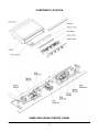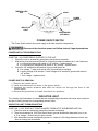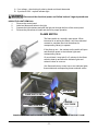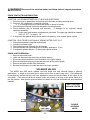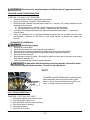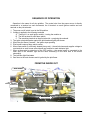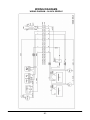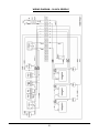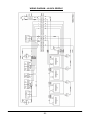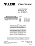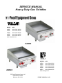
1
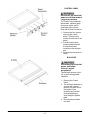
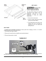
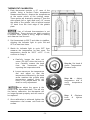
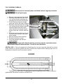
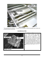
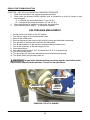
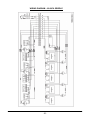
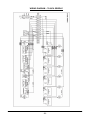
SERVICE MANUAL
Heavy Duty Gas Griddles
MODEL
MLS
924RE
ML-135221-00G24
936RE
ML-135222-00G36
948RE
ML-135223-00G48
960RE
ML-135224-00G60
972RE
ML-135225-00G72
www.vulcanhart.com
924RE
MODELS
AGE24
ITW Food Equipment Group, LLC
3600 North Point Blvd.
Baltimore, MD 21222
MLS
AGE24
ML-135226-00G24
AGE36
ML-135227-00G36
AGE48
ML-135228-00G48
AGE60
ML-135229-00G60
AGE72
ML-135230-00G72
www.wolfrange.com
FORM F-35628 (Rev. 8-07)
TABLE OF CONENTS
INSTALLATION ........................................................................................................................... 4
COMPONENT LOCATION .......................................................................................................................5
948RE AND AGE48 CONTROL PANEL .............................................................................. 5
CONTROL PANEL ............................................................................................................ 6
BULLNOSE ...................................................................................................................... 6
HEAT SHIELD .................................................................................................................. 7
BACK PANEL ................................................................................................................... 7
THERMOSTAT .........................................................................................................................................7
THERMOSTAT TROUBLESHOOTING ............................................................................... 8
SYMPTOM – NO POWER TO THE BURNER SOLENOID ......................................................8
SYMPTOM – GRIDDLE SURFACE TEMPERATURE IS MORE THAN ±15°F OF
THERMOSTAT SET POINT .....................................................................................................8
THERMOSTAT REMOVAL ................................................................................................ 8
THERMOSTAT CALIBRATION .......................................................................................... 9
POWER ON/OFF SWITCH.....................................................................................................................10
POWER SWITCH TROUBLESHOOTING .......................................................................... 10
SYMPTOM – NO POWER BEING SUPPLIED TO THE UNIT ...............................................10
POWER SWITCH REMOVAL ........................................................................................... 10
INDICATOR LIGHT.................................................................................................................................10
INDICATOR LIGHT TROUBLESHOOTING ....................................................................... 10
SYMPTOM – LIGHT DOES NOT COME ON WHEN THERMOSTAT AND BURNER ARE ON
................................................................................................................................................10
INDICATOR LIGHT REMOVAL ........................................................................................ 11
FLAME SWITCH.....................................................................................................................................11
FLAME SWITCH TROUBLESHOOTING ........................................................................... 12
SYMPTOM – INDICATOR LIGHTS AND BURNER VALVES NOT WORKING .....................12
HELPFUL HINT.......................................................................................................................12
FLAME SWITCH REMOVAL ............................................................................................ 12
HELPFUL HINT.......................................................................................................................12
SPARK IGNITER MODULE....................................................................................................................12
SPARK IGNITOR TROUBLESHOOTING .......................................................................... 13
SYMPTOM – NO SPARK BETWEEN PILOT HEAD AND ELECTRODE...............................13
SYMPTOM – ELECTRODE CONTINUALLY SPARKS AFTER PILOT IS LIT........................13
SPARK IGNITOR REMOVAL ........................................................................................... 13
SOLENOID VALVES ..............................................................................................................................13
SOLENOID VALVE TROUBLESHOOTING........................................................................ 14
SYMPTOM – NO GAS FLOW TO BURNER ..........................................................................14
SOLENOID VALVE REMOVAL……………………………………………………………………… 14
PILOT VALVE .........................................................................................................................................14
PILOT VALVE TROUBLESHOOTING ............................................................................... 14
SYMPTOM – PILOT WILL NOT LIGHT ..................................................................................14
PILOT ASSEMBLY REMOVAL ......................................................................................... 15
HELPFUL HINT.......................................................................................................................15
BURNER.................................................................................................................................................15
BURNER TROUBLESHOOTING ...................................................................................... 16
SYMPTOM – ALL BURNERS HAVE A LOWER OR HIGHER FLAME THAN NORMAL .......16
SYMPTOM – ONE OR MORE BURNERS HAVE LOWER FLAME LEVEL THAN THE
OTHERS. ................................................................................................................................16
-2-
SYMPTOM – ONE BURNER HAS A DELAYED IGNITION; A SEVERAL SECOND LAPSE
BETWEEN THE INDICATOR LIGHT TURING ON AND WHEN THE BURNER ACTUALLY
LIGHTS. ..................................................................................................................................16
BURNER REMOVAL ....................................................................................................... 16
BURNER ADJUSTMENT ................................................................................................. 16
GAS REGULATOR .................................................................................................................................17
REGULATOR TROUBLESHOOTING................................................................................ 18
SYMPTOM – UNIT WILL NOT MAINTAIN CONSISTENT PRESSURE.................................18
GAS PRESSURE MEASURMENT .........................................................................................................18
SEQUENCE OF OPERATION................................................................................................................19
FROM THE INSIDE OUT........................................................................................................................19
WIRING DIAGRAMS ..............................................................................................................................20
WIRING DIAGRAM – 24-INCH GRIDDLE.......................................................................... 20
WIRING DIAGRAM – 36-INCH GRIDDLE.......................................................................... 21
WIRING DIAGRAM – 48-INCH GRIDDLE.......................................................................... 22
WIRING DIAGRAM – 60-INCH GRIDDLE.......................................................................... 23
WIRING DIAGRAM – 72-INCH GRIDDLE.......................................................................... 24
-3-
GENERAL
INTRODUCTION
This manual is prepared for the use of trained service technicians and should only be used by those
who are properly qualified. This manual is not intended to be all encompassing. You should read, in
it's entirety, the repair procedure you wish to perform to determine if you have the necessary tools,
instruments and skills required to perform the procedure. Procedures for which you do not have the
necessary tools, instruments and skills should not be attempted.
Disconnect the electrical power and follow lockout / tagout procedures
Certain procedures in this manual require electrical test or
measurements while power is applied to the machine. Exercise extreme caution at all
times when attempting these procedures. Before testing, disconnect electrical power
and follow lock/out tagout procedures, then attach test equipment and reapply power to
test.
Procedures in this manual will apply to all 900RE and AGE models unless specified. No procedure
in this manual will require the removal or raising of the griddle plate. Pictures and illustrations can be of
any model unless the picture or illustration needs to be model specific.
INSTALLATION
Generally, installations are made by the dealer or contracted by the dealer or owner. Detailed
installation instructions are included in the Installation and Operation Manual that is sent with each unit.
However, it should be noted that an improperly installed unit, especially an unlevel unit can lead to
premature electrical component failures. A unit that is higher in the front will cause the flue gases to
vent improperly and gather in the front near the electrical components. All 900RE and AGE models
must be installed with an externally mounted regulator.
OPERATION
Detailed operation instructions are included in the Installation & Operation Manual sent with each
unit and are also available at WWW.VULCANHART.COM .
CLEANING
Detailed cleaning procedures are included in the Installation & Operation manual sent with each
unit.
LUBRICATION
No lubrication is required on this equipment.
SPECIFICATIONS
All 900RE and AGE models operate on 120 volt, 60 hertz, single phase at 0.5 amps. All models are
equipped with electric snap-action thermostats, automatic spark igniters and pilot flame safety switches.
All models are equipped with 30,000 BTU/HR burners as standard equipment. One burner is used for
every 12 inches of griddle surface. Natural gas models are to operate at 5.0" W.C. manifold pressure
and LP models at 10.0" W.C. manifold pressure with main burners on.
-4-
COMPONENT LOCATION
948RE AND AGE48 CONTROL PANEL
-5-
CONTROL PANEL
Disconnect the electrical
power and follow lockout
/ tagout procedures
The Control Panel holds the
thermostats, indicator lights
and power switch, and is
connected to the Control
Plate with a Panel Connector
1. Remove the four screws
securing the control
panel. There are two
screws at each end of the
panel.
2. Pull the control panel
forward and disconnect
the electrical panel
connector near the right
end.
3. Reverse the procedure to
install.
BULLNOSE
Disconnect the electrical
power and follow
lockout / tagout
procedures
The Bullnose acts as a front
rail or shelf during griddle
operation.
1. Remove the Control
Panel.
2. The bullnose assembly is
secured with several
screws, one each end of
the bottom of the
assembly and several
more (depending on
size) facing the griddle
plate.
3. Reverse the procedure
to install.
-6-
HEAT SHIELD
Disconnect the
electrical power and follow
lockout / tagout procedures
The heat shield protects the electrical
components and should only be
temporarily
removed
for
easier
replacement of some the control
components.
1. Remove the control panel.
2. Remove screws along the top edge
that secure the heat shield.
3. The shield clamps on the front of the
chassis and can be removed by
grasping the top of the shield and
pulling forward.
BACK PANEL
It should only be necessary to remove the back panel when changing a burner or to remove
excessive grease build up from the flue area.
1. Disconnect gas supply at griddle.
2. Remove all screws from rear of griddle securing the back panel.
3. Reverse the procedure to install.
THERMOSTAT
Thermostat
Capillary
bulb
Capillary wire insulation
The thermostat is a snap action, single pole – single throw type. The thermostat supplies power to
the main burner solenoid valves when turned on or until the temperature set point is reached.
-7-
Disconnect the electrical power and follow lockout / tagout procedures
THERMOSTAT TROUBLESHOOTING
SYMPTOM – NO POWER TO THE BURNER SOLENOID
1. Check for loose or excessively greasy/dirty connections at terminals
2. Check for continuity/resistance between the two thermostat terminals with wires disconnected
A. If you get continuity/resistance with the thermostat off or open – replace thermostat
B. If you do not get continuity or resistance with thermostat on or closed – replace
thermostat
3. Check flame switch for continuity/resistance and voltage
4. Check for voltage from hot line
A. If no voltage check wiring for shorts or breaks
SYMPTOM – GRIDDLE SURFACE TEMPERATURE IS MORE THAN ±15°F OF THERMOSTAT SET
POINT
1. Ensure that you are using a high quality, calibrated surface temperature measuring device.
A. Do not use an infrared thermometer – these are highly inaccurate on a griddle plate.
B. Refer to instructions on the proceeding page for proper placement of probe and method.
2. Check that burners are properly adjusted.
3. Check that burner valves are operating correctly.
4. Check that there are no burner orifice obstructions
5. Check that thermostat capillary bulb is completely seated back as far as possible in the groove
on the bottom of the plate. No part of the bulb should be exposed from behind the bulb heat
shield.
6. Check that the high temp. capillary wire insulation is completely covering capillary wire from the
connection at the thermostat to the beginning of the bulb and that the insulation is not damaged
or burned thru. If insulation appears damaged – replace the insulation.
7. If you have found no problems in steps 1 – 6, proceed to the next page for calibration
instructions.
8. If thermostat will not calibrate after all previous steps – replace thermostat.
THERMOSTAT REMOVAL
1. Remove the control panel
2. Remove the knob
3. Label and disconnect the wires
4. Remove the two screws and two washers securing the thermostat dial and thermostat to the
Control panel.
5. Remove the heat shield.
6. Pull the capillary bulb straight out from the plate groove.
7. Reverse the procedure to install while ensuring that capillary bulb is completely seated – all the
way to the back of the plate groove.
8. Check that capillary wire is completely covered with insulation from the connection at the
thermostat to the beginning of the sensor bulb.
-8-
THERMOSTAT CALIBRATION
1. Each thermostat controls a 12” zone of the
griddle. Using a Surface Probe temperature
measurement device, observe the temperatures
at the center points of the cooking zones.
These points are located by starting 6” from the
side splash (left or right) and every 12” across
the width of the griddle, with all points located
12” back from the front edge of the griddle
plate.
Use of infrared thermometers is not
recommended. These devices are highly sensitive
to surface color (clean or dirty), angle of reading
and distance from the unit.
2. Set thermostats to 350°F and allow to stabilize,
allowing the indicator light to cycle ON and
OFF at least two times.
3. Watch for indicator light to cycle OFF, then
measure the temperature for that zone. The
temperature should be 350°F ±15°F. If not,
continue to Step 4.
4.
a. Carefully loosen the knob set
screw. DO NOT allow the knob to
turn. Carefully remove the knob
from
the
thermostat
shaft,
exposing the temperature dial.
b. Loosen screws on the temperature
dial and adjust so that the
temperature indicated by the knob
arrow matches the griddle plate
temperature reading. Knob will
have to be placed back on the
shaft to verify adjustment.
Never adjust the screw in the
center of the thermostat shaft. This will ruin
the factory calibration; the thermostat will
no longer operate properly and will need to
be replaced.
5. Once calibration is achieved, tighten the
temperature dial screws and knob set
screws.
-9-
Step 4a. Set knob &
check Temperature.
Remove knob
Step 4b. – Adjust
temperature dial &
verify
temperature
setting
Step
5
–Replace
knob
&
tighten
screws
TEMPERATURE
DIAL
KNOB
POWER
SWITCH
INDICATOR
LIGHT
KNOB GUARD
(OPTIONAL)
POWER ON/OFF SWITCH
The Power Switch controls the power supply to all other electronic components.
Disconnect the electrical power and follow lockout / tagout procedures
POWER SWITCH TROUBLESHOOTING
SYMPTOM – NO POWER BEING SUPPLIED TO THE UNIT
1. Check for loose or excessively greasy/dirty connections at terminals.
1. With power wires disconnected check for continuity/resistance between the 1 and 2 terminals
A. If continuity/resistance with switch in “off” position – replace switch
B. If no continuity/no resistance with switch in “on” position – replace switch
3. Check for 120 voltage from #2 terminal to ground with power on
A. If no voltage – check main wiring from j box and power cord/plug
B. If getting voltage to #2 terminal – check voltage to #1 terminal to ground with switch in
“on” position.
1. If no voltage – replace switch
POWER SWITCH REMOVAL
1. Remove the control panel.
2. Label and disconnect the wires to the power switch.
3. Squeeze the switch retainers and slide the switch out through the front of the
control panel.
4. Reverse the procedure to install and check for operation.
INDICATOR LIGHT
The indicator light illuminates to indicate that the corresponding thermostat and burner have turned on
and gas is flowing through the corresponding solenoid valve.
INDICATOR LIGHT TROUBLESHOOTING
SYMPTOM – LIGHT DOES NOT COME ON WHEN THERMOSTAT AND BURNER ARE ON.
1. Check for loose or excessively greasy/dirty terminal connections
2. There should always be 120V from the hot wire to ground whether the thermostat is on or not.
A. If no voltage – check wiring for short or break.
3. With thermostat on and corresponding burner lit – check for 120 voltage between hot wire and
the wire coming from thermostat.
- 10 -
A. If no voltage – check wiring for short or break and check thermostat
B. If you have 120V – replace indicator light.
Disconnect the electrical power and follow lockout / tagout procedures
INDICATOR LIGHT REMOVAL
1.
Remove the control panel
2.
Label and disconnect wires to the light
3.
Squeeze the light retainers and slide the light out through the front of the control panel
4.
Reverse the procedures to install and check for proper operation
FLAME SWITCH
The flame switch is a normally open sensor. When
immersed in an active pilot flame, it will close electrical
contacts to complete the circuit that allows its
corresponding valve(s) to operate.
If the pilots go out – the contacts on the switch will open
and shutdown power to the indicator lights and
corresponding valves.
On a cold start, it may take 2 or 3 minutes for the flame
switch to heat up and allow the indicator lights and
solenoid valves to come on.
One flame switch may control one or two indicator lights,
thermostats and corresponding burner solenoid valves.
PILOT HOOD
FLAME SWITCH PROBE
IGNITOR
ELECTRODE
SNAP IN RETAINER
EXAMPLE OF FLAME SWITCH PROBE THAT IS PROPERLY ENGULFED IN THE PILOT FLAME
- 11 -
Disconnect the electrical power and follow lockout / tagout procedures
FLAME SWITCH TROUBLESHOOTING
SYMPTOM – INDICATOR LIGHTS, THERMOSTATS AND BURNER VALVES NOT WORKING
1. Check for loose or excessively greasy/dirty terminal connections
2. Check that flame switch probe is fully engulfed in the pilot flame and glowing cherry red.
A. If sensor is not glowing red and/or not engulfed in pilot flame
1. Check gas pressure and adjust pilot flame for proper impingement; clean pilot if
necessary
2. Check that sensor has not fallen out of the snap in retainer
3. Check that there is 120 voltage from the “NO” terminal to ground with the power switch on.
A. If no voltage – check wiring for shorts
4. Check for 120 voltage from “C” terminal to ground with sensor glowing red
A. If no voltage and steps 1 -3 were completed, replace flame switch
HELPFUL HINT – A quick way to check for a flame switch problem is to take a jumper line and connect
the two terminals on the switch – if the corresponding thermostats, indicator lights and solenoid valves
all begin to immediately function, then you know there is a problem in that area. Never leave the unit to
run with a jumped flame switch after making the check.
FLAME SWITCH REMOVAL
1. Remove the control panel.
2. Label and disconnect the wires to the flame switch.
3. Remove the two screws securing the switch to the control bracket.
4. Reach under the unit and pull the flame switch sensor straight down and out of the snap in
retainer.
5. Pull the flame switch out the front of the unit while guiding the sensor wire out through the
corresponding whole in the chassis.
6. Reverse the procedure to install. Be sure to carefully route and attach the sensor to the pilot
assembly and check for proper operation.
HELPFUL HINT – If the unit is attached to a flexible gas line, the bullet feet can be adjusted out to their
fullest extension to raise the griddle and allow more clearance to reach under the unit. Remember to
relevel the unit if you chose to do this.
SPARK IGNITER MODULE
L1 TERMINAL
N TERMINAL
GROUND
SPADE
ELECTRODE WIRE
TERMINMAL
- 12 -
The spark igniter module is
a single point gas re-igniter
that incorporates a flame
rectification sense circuit.
If there is an absence of
pilot flame, the igniter will
begin to spark.
Disconnect the electrical power and follow lockout / tagout procedures
SPARK IGNITOR TROUBLESHOOTING
SYMPTOM – NO SPARK BETWEEN PILOT HEAD AND ELECTRODE
1. Check for loose or greasy/dirty connections at all terminals (including electrode wire)
2. Check for 120 voltage from L1 terminal to ground
a. If no voltage check on/off switch and wiring for shorts or breaks
3. Check that ground spade is securely attached to mounting bracket.
4. Check electrode wire for damage and continuity – if damaged or no continuity change
spark/pilot assembly
a. Check spark gap between electrode and pilot head. The spark gap should be between
.098” to 0.157” – or approx. 1/8”.
5. If component has passed above checks and is not sparking – then replace igniter module.
SYMPTOM – ELECTRODE CONTINUALLY SPARKS AFTER PILOT IS LIT
1. Check that electrode is engulfed by pilot flame
2. Increase pilot flame height
3. Check electrode and electrode wire for damage
4. Check that power cord grounding wire is securely attached to “J” box.
5. If component passes checks 1 -4, then replace igniter module
SPARK IGNITOR REMOVAL
1. Remove the control panel.
2. Label and disconnect the wires from the igniter module.
3. Disconnect the electrode wire from the bottom of the igniter module
4. Remove the bottom mounting screw and the screw at the ground spade.
5. Remove the igniter module from the bracket.
6. Reverse the procedure to install and check for proper operation.
SOLENOID VALVES
The 900RE and AGE series griddles use both single and dual solenoid valves in differing
applications. A single or dual valve can be either a pilot valve or main burner valve. Pilot valves can
be identified by the fact that they will have adjustment screws for the pilot flame at the output of the
valve body. Pilot solenoid valves will receive power and remain on as long as the power switch is in
the ON position. Main burner solenoid valves will remain on until the thermostat set point has been
satisfied.
INPUT GAS LINE
IN BACK CENTER
RETAINING SCREW
Retaining screw
OUTPUT
GAS LINES
- 13 -
DOUBLE
SOLENOID
VALVE
Disconnect the electrical power and follow lockout / tagout procedures
SOLENOID VALVE TROUBLESHOOTING
SYMPTOM – NO GAS FLOW TO BURNER
1. Check terminals for loose or greasy/dirty connections
2. Check gas pressure – check for orifice obstructions.
3. With thermostat, indicator light and power switch on – check for 120 voltage between the two
terminals on the solenoid.
A. On pilot solenoid if no voltage – check wiring and on/off power switch
B. On main burner solenoid if no voltage – check wiring and thermostat
4. If you have 120 voltage between the two terminals after performing steps 1- 3, replace the
solenoid valve.
5. Check for a shorted coil by checking resistance between the two terminals with the wires
disconnected. Readings of 100 ohms or less would indicate a shorted coil, replace the
solenoid.
SOLENOID VALVE REMOVAL
Shut off gas supply
1.
2.
3.
4.
5.
6.
7.
Remove the control panel.
Label and disconnect the wires to the solenoid terminals.
Remove the two retaining screws that are holding the valve body in the bracket.
Disconnect the input compression fitting and the output compression fitting(s).
Remove the solenoid valve
Reverse the procedure to install. Be careful to attach the input lines to the ports on the valve
body that are stamped “IN”
Verify gas pressure and check for proper operation.
All gas joints disturbed during servicing must be checked for leaks.
Check with a soap and water solution. Do not use an open flame.
PILOT
BRASS PILOT
VALVE
The 900RE and AGE Griddles utilize a solenoid valve
with a brass pilot valve to control gas flow to pilot
burners. One to three pilot flames can be fed by one
valve – one leg of which may be branched.
PILOT TROUBLESHOOTING
SYMPTOM – PILOT WILL NOT LIGHT
1. Check pilot adjustment at solenoid valve
2. Check that power switch is on
3. Check that pilot solenoid valve is working
4. Check that igniter is working
5. Check gas pressure
6. Check for air in the line
- 14 -
PILOT ASSEMBLY REMOVAL
Disconnect the electrical power and follow lockout / tagout procedures
Shut off gas supply
1. Remove control panel and heat shield
2. Reaching underneath the front of the
unit, remove the pilot tube fitting and
disengage the pilot tube from the pilot.
3. Pull the flame switch probe straight
down and out from the snap in retainer.
4. Reaching underneath the front of the
unit, remove the pilot bracket retaining
screw(#2 Phillips) and remove the
entire assembly out through the pilot
access cutout and out from under the
unit.
5. Disconnect the electrode wire from the
from the bottom terminal of the spark
igniter module.
6. Remove the pilot from the bracket.
7. Reverse procedure to install
8. Verify gas pressure and check for
proper operation
BRACKET RETAINING SCREW
FLAME SWITCH PROBE
PILOT ASSEMBLY
SNAP IN RETAINER
PILOT TUBE FITTING
PILOT ACCESS CUTOUT
All gas joints disturbed during servicing must be checked for leaks.
Check with a soap and water solution. Do not use an open flame.
HELPFUL HINT – If the unit is attached to a flexible gas line, you can extend the bullet feet out to their
fullest extension to raise the griddle and allow yourself more clearance while reaching under the unit.
Remember to relevel the unit if you chose to do this.
BURNER
The 900RE and AGE utilize “U”-shaped burner with a single center inlet for every 12 inches of
griddle width. Each burner is rated for 30,000 BTU/hr.
- 15 -
Disconnect the electrical power and follow lockout / tagout procedures
BURNER TROUBLESHOOTING
SYMPTOM – ALL BURNERS HAVE A LOWER OR HIGHER FLAME THAN NORMAL.
1. Check gas pressure
SYMPTOM – ONE OR MORE BURNERS HAVE LOWER FLAME LEVEL THAN THE OTHERS.
1. Check gas pressure
2. Check burner orifice for obstructions
3. Adjust burner air shutter
4. Check solenoid valve
SYMPTOM – ONE BURNER HAS A DELAYED IGNITION; A SEVERAL SECOND LAPSE BETWEEN
THE INDICATOR LIGHT TURING ON AND WHEN THE BURNER ACTUALLY LIGHTS.
1. Check gas pressure
2. Check that burner locater pin is properly seated with retaining clip attached
3. Check that burner ignition ports, pilot flash tube and pilot burner are all aligned.
4. Check burner shutter adjustment
5. Check pilot flame adjustment
6. Check thermostat and solenoid valve operation.
BURNER REMOVAL
Shut off gas supply
1.
2.
3.
4.
5.
6.
7.
Remove the back panel
Reach through the back of the unit. Squeeze the burner retaining clip and slide off burner
retaining pin.
Lift the burner up so the retaining pin clears the corresponding hole in the chassis, then pull
the burner out through the back of the unit.
Replace by inserting the burner through the rear of the unit and engaging the burner venturi
onto the burner orifice at the front of the unit.
Seat the retaining pin in the hole in the chassis and attach the retaining clip.
Remove the control panel to check that the venturi is properly fitted over the orifice.
Reassemble the control and back panels, then check for proper operation.
BURNER ADJUSTMENT
For efficient burner operation, it is important that a proper balance of gas volume and primary air
supply is maintained to give complete combustion. Insufficient air supply results in a yellow streaming
flame. Primary air supply is controlled by the air shutter on the front of the burner venturi. Loosen the
screw on the venturi and adjust the air shutter to just eliminate yellow tips on the burner flames. Lock
the air shutter in place in place by tightening the screw. Repeat this procedure as necessary with all
burners.
- 16 -
BURNER CLIP
(UNDERNEATH)
FLASH TUBE
PILOT ASSY
IGNITION PORTS
AIR SHUTTER
ORIFICE
MAIN BURNERS
These photos are for reference – it should not be necessary to remove the griddle top to perform the
procedures listed in this manual.
GAS REGULATOR
VENT LIMITER
REGULATOR INSTALLED
UPRIGHT POSITION
ADJUSTMENT
COVER
IN
A
HORIZONTAL,
- 17 -
The 900RE and AGE series units must
have an exterior machine gas regulator
installed. The units are shipped with a
regulator that has a vent limiter. These
regulators must be installed as close as
possible to the unit in a horizontal, upright
position for optimal performance. They are
adjusted by removing the adjustment cover –
then by turning the adjustment screw to the
right to increase and to the left to decrease.
The regulator and griddle can be damaged
by gas pressures that exceed 14” W.C. or ½
psig.
REGULATOR TROUBLESHOOTING
SYMPTOM – UNIT WILL NOT MAINTAIN CONSISTENT PRESSURE
1. Check that vent limiter is not clogged by grease and debris
2. Check store gas pressure before regulator with all equipment on that line turned on and
consuming gas
A. For natural gas should be between 7” and 14” W.C.
B. For propane gas should be between 12” and 14” W.C.
3. Check that regulator is installed in a horizontal, upright position
4. If no problems found in steps 1 – 3, replace the regulator
GAS PRESSURE MEASURMENT
1. Set the power on/off switch to the OFF position.
2. Turn the gas supply off at a manual shutoff valve.
3. Remove the control panel.
4. Remove the pressure tap plug from the far left/#1 burner port and attach manometer
5. Turn gas back on and turn power switch to the ON position
6. Turn all thermostats on to the maximum setting so that all burners are on.
7. Turn all the equipment on the same supply line on.
8. Check gas pressure
9. Gas pressure should read 5” W.C. for natural and 10” W.C. for propane gas.
10. Turn off the power switch.
11. Turn gas supply off, disconnect manometer and reinstall pressure tap plug.
12. Turn power switch and gas supply back on.
All gas joints disturbed during servicing must be checked for leaks.
Check with a soap and water solution. Do not use an open flame.
FLAME SWITCH
PRESSURE TAP
SPARK
IGNITOR
MODULE
PRESSURE TAP AT #1 BURNER
- 18 -
SEQUENCE OF OPERATION
Operation is the same for all size griddles. The neutral wire from the power source is directly
connected to a terminal on each thermostat, the N terminal on each ignition module and one
terminal on the pilot solenoid.
1. The power on/off switch is set to the ON position.
2. Voltage is applied to the following terminals
A. Terminal L1 on each igniter module – turning the module on
B. The NO terminal of each flame switch
C. The remaining terminal on the pilot solenoid – energizing the solenoid
3. The igniter electrode sparks against the pilot head and lights pilot burner
4. When the pilot flame is sensed – the igniter stops sparking
5. Pilot burner heats up flame switch sensor
6. When flame switch is sufficiently heated (cherry red) – the switch closes and supplies voltage to
one terminal on each burner solenoid and one terminal on each indicator light
7. When a thermostat is rotated out of the OFF position – the neutral return is connected to the
other side of the indicator light and the other terminal(s) on the other side of the burner
solenoid(s)
8. The indicator light illuminates
9. Gas flows to the main burners and is ignited by the pilot flame.
FROM THE INSIDE OUT
WIRE HARNESS
SPARK IGNITOR
ORIFICE
FLAME SWITCH
HARNESS
CONNECTOR
3/8” FLEX TUBE
MANIFOLD PIPE
- 19 -
SOLENOID
VALVE
WIRING DIAGRAMS
WIRING DIAGRAM – 24-INCH GRIDDLE
- 20 -
WIRING DIAGRAM – 36-INCH GRIDDLE
- 21 -
WIRING DIAGRAM – 48-INCH GRIDDLE
- 22 -
WIRING DIAGRAM – 60-INCH GRIDDLE
- 23 -
WIRING DIAGRAM – 72-INCH GRIDDLE
- 24 -