1
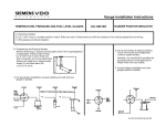
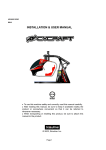
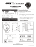
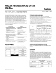
CAUTION!!! l North America Tachometer Installation and Operation Instructions for Programmable Tachometer with Hourmeter Instruction Sheet # 0 515 012 037 Rev. 03/01 INSTRUCTIONS FOR THE INSTALLATION AND OPERATION OF THE PROGRAMMABLE TACHOMETER ARE CONTAINED HEREIN. USE IS RESTRICTED TO 12-VOLT OR 24VOLT NEGATIVE GROUND ELECTRICAL SYSTEMS. If in doubt, please contact your dealer or VDO North America at (540) 6652428. CAUTION; Read these instructions thoroughly before installing the tachometer. Do not deviate from assembly or wiring instructions. Always disconnect the battery ground before making any electrical connections. General Information The VDO Programmable Tachometers featured in this installation manual are available in three diameters: 3 ¹⁄₈" (80 mm); 3 ³⁄₈" (85 mm), and 4" (100 mm). All tachometers can be programmed to function with gasoline engines or with diesel engines, and can be used with most ignition coils. These instructions describe the installation, wiring, calibration and operation of all VDO Programmable Tachometers.. Each tachometer’s analog display clearly shows the number of revolutions per minute, and the LCD display shows the accumulated engine hours. This display is also used in the programming , calibration and fine tuning of the VDO Programmable Tachometer. Signal pulses needed by the tachometer are provided by the ignition coil, an alternator [AC tap], a HallEffect sender, or an inductive sender, depending on the type of engine. If you are not sure where to tap the ignition to get the necessary signal, consult your operator’s manual or contact the engine manufacturer. Tools and Materials Needed For Installation: Hole saw or jigsaw (may not be needed) ¼" spade terminals Miscellaneous electrical connectors Philips and/or flathead screwdriver Pliers and/or wrenches Crimping tool and/or soldering iron (may not be needed) These instructions contain information about gauges of different sizes. You must determine the size of your gauge before cutting any holes! Parts List Item Description 1. 2. 3. 4. 5. Quantity Tachometer Lamp Socket (Push in, wedge-type) Light Bulb (12-volt / G.E. #161 or equivalent) VDO Spin-Lok™ Mounting Clamp Installation/Operation Instructions 1 2 2 1 1 Sensor Installation II. Wiring the Tachometer The sensor necessary to provide the signal to your new VDO Tachometer is not included. This sensor is available from your auto parts dealer. (Part numbers for VDO Hall Effect Sensors are: 340 011; 340 012; 340 013; and 340 014. The VDO Generator Sensor is Part #340 001. VDO’s Inductive Sensor is Part # 340 020.) 1. Prepare insulated ¼" spade terminals for use with the tachometer. Make sure all wires are long enough to reach the necessary positive and negative terminals and any wires from the sensor. I. Mounting the Tachometer 1. Refer to Diagram B for dimensions. The 3 ¹⁄₈ " (80 mm) tachometer requires a hole diameter of 3 ¹⁄₈" (80mm); the 3 ³⁄₈ " (85 mm) tachometer requires a hole diameter of about 3 ³⁄₈ " (85mm); and the 4 " (100 mm) tachometer requires a hole diameter of about 4 " (100 mm). If you are mounting the tachometer into an existing panel, remember that the panel cannot be more than ¾" (20 mm) thick. Minimum mounting depth is 3 ⁹⁄₁₆ " (91mm). 2. Careful measuring is a must for proper mounting of your tachometer. An improperly placed hole would be a costly mistake, so measure everything twice. REMEMBER: THERE ARE NO SECOND CHANCES ONCE YOU HAVE MADE YOUR HOLE! MEASURE TWICE... CUT ONCE! 3. Cut the hole. If you do not have a hole saw the exact size needed, use the closest SMALLER size, and carefully widen the hole with a half-round file or other similar device. 4. Note: If you plan to calibrate your tachometer, perform this step LAST! Place the tachometer in the opening and secure it with the supplied VDO Spin-Lok clamp as shown in Diagram C. You may also mount the tachometer using an optional VDO mounting bracket and nuts. 2. Connect the wire from pin #4 to a switched +12 volt or +24 volt source. A switched +12 or 24 volt wire can be found coming from the ignition switch. Follow this wire to a junction, and attach the wire from pin #4 at this junction (i.e. fuse block, etc.). Refer to Diagram D. 3. Connect a wire from pin #5 to a constant +12 or +24 volt source. 4. Attach the wire from pin #3 to a ground (negative) source. One such source can always be found where the battery is attached to the metal frame of the vehicle. Use an appropriate connector to ground this wire. 5. Attach the wire from pin #8 to the positive (+) tachometer signal source [usually a terminal on the ignition coil or the generator in a diesel system] using a butt splice and a crimping tool. 6. Attach the wire from pin #7 to the negative (–) terminal of the sender or floating ground [usually a terminal on the ignition coil or the generator in a diesel system] using a butt splice and a crimping tool. 7. Crimp a spade connector onto a short wire, and attach the connector to a terminal on one of the supplied lamp sockets. This lamp socket is referred to as Socket A. 8. Crimp the other end of the short wire, along with [text continues at #] ¨ RPM -²1³ 8_ecY^W4YQ]UdUb !)%]] 2UjU\4YQ]UdUb ® 2edd_^V_b SQ\YRbQdY^WdQSX_]UdUb !) $(]] Tachometer: “A” “B” VDO VDO 3¹⁄₈" (80 mm) 3¹⁄₈" (80 mm) 3.32" (84 mm) 3³⁄₈" (85 mm) 3³⁄₈" (85 mm) 3.56" (89 mm) 4" (100 mm) 4" (100 mm) 4.16" (104 mm) Diagram A VDO Tachometer with Hourmeter is programmable from .5 to 200 pulses per revolution Diagram B VDO Programmable Tachometer Dimensional Drawings DQSX CYW^Q\* <YWXd CgYdSX 6ecU 2\_S[ 2QddUbi 3_Y\ 9W^YdY_^ _b 5\USdb_^YS 3_^db_\2_h _b D? @Y^$ @Y^( DQSX_]UdUb @Y^# 7b_e^T 13DQ`]Qb[UT²G³_b²B³±4YUcU\1``\YSQdY_^c 1\dUb^Qd_b <YWXd CgYdSX 6ecU 2\_S[ 3@@7>E 9W^YdY_^ ?B D? @Y^( @Y^' @Y^$ @Y^# DQSX_]UdUb 7b_e^T ±4YUcU\Q``\YSQdY_^c± 7U^UbQd_b cU^TUb 9^TeSdYfU cU^TUb Diagram D Proper wiring of the tachometer with: ➊ Ignition; Electronic Control Box; alternator* Generator* and Inductive* senders *diesel applications To use the ! +#$% &'! ! "#$% &'! )*'! (optional) b !( " !( $ " 2. Manual Calibration with a known value ( ) Diagram C If you know the exact calibration value for the vehicle and type of sensor you are using (pulse-per-revolution), you may use that value to manually calibrate the tachometer. Proper mounting of the VDO Tachometer a second piece of wire (long enough to reach the light switch) into another spade connector. Attach this connector to a terminal on the remaining lamp socket, which will be referred to as Socket B. 9. Reconnect the battery and turn on the ignition to make sure the tachometer is working. When you turn on the ignition, the tachometer will do an automatic selftest. During this self-test, the pointer moves over the whole scale range, and the LCD display shows the word “ .” After the test is completed, the display will show the current working hour on the engine hourmeter. Since this is the first time power has been applied to the instrument, the reading will be 0.0. (See Diagram E.) If everything is working properly, the installation is complete. If it isn’t, re-check your wiring and your connections and try the self-test again. The display lists the cylinder/engine-type selection mode as ; the impulse-per-revolution mode as ; and the reference/fine-tune mode as . When you see the method you wish to use, let go of the button and that function will be enabled. See Diagram F. After test Diagram E The LCD on the tachometer will show this display III. Calibrating the Tachometer Calibration modes as displayed on the Tachometer’s LCD 1. Programming the Cylinder/Engine type ( ) Programming the tachometer for the number of cylinders in your gasoline engine can be done easily using the mode. Calibration of the VDO Tachometer with Hourmeter is a relatively simple procedure, and can be accomplished in any of three ways: · · · By programming in the number of cycles and the number of cylinders in the gasoline engine you are using... By the input of the known pulse-per-revolution for the diesel engine and ignition system being used with the tachometer... Using a reference point for adjustment or fine tuning. The display lists the select mode as ; the pulse-permile mode as ; and the reference/fine-tune mode as xxxxxxx . When you see the method you wish to use, let go of the button and that function will be enabled. See Diagram F. You gain access to the calibration functions by pressing the button on the back of the tachometer and holding it in while you turn on the ignition. As you continue to hold in the button, the display will change...scrolling through the three calibration methods and stopping on each one for about two seconds. 1. Press and hold in the button on the tachometer as you start the engine. Hold in the button until the word “ ” is displayed on the LCD readout. 2. As soon as you see the word “ ,” release the button. After a few seconds, the display will start flashing a series of numbers (factory default setting) that you can change to represent the impulse-per-revolution value of the ignition in your vehicle. For example, a number like “P 14.70” will show on the display, with each digit flashing in turn from right to left, except the right-most digit, a zero, which is fixed. For example, let’s say the number that represents the correct calibration value for the diesel engine and ignition system in your vehicle is 16.5 pulses-per-revolution. When you begin the manual calibration process, the LCD displays a default value. When the first digit starts flashing, press the button to start cycling through the numbers. When the number “5” appears, release the button. Diagram F During test To calibrate your VDO Tachometer manually: 3. As each number flashes, press the button and hold it until the correct digit appears. Refer to Diagram H. VDO VDO mode: 1. Press the button on the back of the tachometer, hold it in, and turn on the ignition. Release the button when the tachometer display reads, “ .” 2. Now you must enter two values: one for the number of cycles in the engine you are using; the second for the number of cylinders in the engine. To program the tachometer for use with a 4-cycle, 6-cylinder engine, for example, push and hold the button until the digit “4” appears. Release the button for a second, then push and hold it again, until the digit “6” appears, as shown in Diagram G. Then release the button. After several seconds, the display will automatically revert to its normal mode. At this point, the number “5” is set, and the digit to its immediate left begins to flash. Press the button again, and hold it until the number “6” appears. Release the button. Repeat the procedure until the “1” appears. Again, release the button. At this point, the correct calibration for the tachometer/ignition combination has been properly set...in our example, 16.5 pulses-per-revolution. After a few seconds, the value you have entered will be downloaded into the tachometer’s microprocessor, and the LCD display will automatically revert to its normal mode. Manual calibration of the tachometer is now complete. In the future, you can use this method to update the calibration value stored in the computer should it ever become necessary. This function also allows you to manually adjust the calibration value after you perform the automatic calibration process. [text continues at #] ¨ VDO then 4-2C then 4-6C VDO Hold button in until the leftmost digit rotates to the number “4.” Then release the button briefly. Hold in the button again until the correct number of cylinders comes up — in this example, “6C.” When finished, release the button. The display will show the correct number of cycles and cylinders for your engine...in our example, 4 cycles and 6 cylinders. then then A number comes up when you release the button. Digits begin flashing, starting with the second digit from the right. Diagram G Diagram H LCD Sequences as they appear when programming in the “SELECT” mode LCD Sequences that appear when calibrating in the “PULSE” mode 3. Analog (Pointer) Calibration ( ) You can adjust the calibration of the tachometer’s analog display (the pointer showing revolutions per minute) by using speed test equipment and the “ ” function on the LCD readout. The pointer can be repositioned anywhere within the calibration range of the tachometer. To manually calibrate the pointer on the analog display: 1. Press and hold in the button on the tachometer as you turn on the ignition and start the engine. Hold in the button until the word “ ” shows up. When it does, release the button. Set the RPM using a reference tachometer at a value above idle (e.g. 2000 RPM). 2. Press the button once, and the word “ ” will be displayed on the LCD readout. Press it twice rapidly then release it for a second, and the word “ ” will be displayed. So if you need an upward calibration of the pointer, press the button once. If you need a downward calibration, press the button twice rapidly and release it. 3. When either “ ” or “ ” is showing, press the button again, and hold it in. If you hold the button in for just a short time, the pointer will move slowly either upwards or downwards, depending on which mode you selected. This allows for a very accurate adjustment of the pointer. Holding the button in for a longer period of time makes the pointer move faster. Adjustments between – 30% and +100% are possible, but must be done WITH A REFERENCE TACHOMETER ONLY!!! NOTE: If you move the pointer past the upper limit of the calibration range, the LCD display will flash and you will only be able to adjust the pointer downward. If you move the pointer past the lower calibration limit, the LCD display will also flash, and you will only be able to adjust the pointer upward. TECHNICAL DATA Operating voltage: 10.8 – 32 Volts Operating current: < 100 mA (< 600 mA with light) 4. Fine Calibration When the ignition is on and power is supplied to the tachometer you can select the fine calibration function to very accurately adjust the running speed — difference ratio. This allows for compensation of alternator slippage over various speed ranges, for example. This function also allows for syncronization of two engines. Operating temperature: – 4° F to 158° F (-20° C to 70° C) Protection: To access and use the fine calibration function: 1. Press and release the pushbutton on the back of the tachometer. This enables you to adjust the running speed/difference ratio between –20% and +20%. Adjustments are made in (+) or (–) steps of 0.5% by pressing and holding the button. When the adjustment is complete, release the button. After a short time, the display reverts back to its normal mode. See Diagram J for examples of: Display 1: 0.0% difference to the adjusted value; Display 2: 2.0% difference to the adjusted value; Display 3: 2.5% difference to the adjusted value. IP65 (Front) Ozone and UV resistant housing Dimensions — Depth: 3.6" (91 mm) Diameter: 3 ¹⁄₈" (80 mm) 3 ³⁄₈" (85 mm) 4" (100 mm) Illumination: Backlit / Frontlit dial and display Calibration range: 0.5 to 200 pulses per revolution TO COMPLETE THE INSTALLATION: It is recommended that these adjustments be done only by experienced mechanics. Perform Step 4 of Section One on Page 1. When the tachometer is secure in the panel, your installation is finished. 4. When you have repositioned the pointer where you want it, release the button and wait. If no further adjustments are made within one minute, the tachometer will revert back to the normal operating mode. $%&' ()* + , %'-.)(/0+ ) 01.&)2 3.0)1&0 %4- ' (5+6' 72 VDO VDO Example #1 then Adjust pointer by pushing and holding in the button on the rear of the tachometer Example #2 or Example #3 Diagram I Diagram J Calibration of the analog (pointer) display on the tachometer Fine calibration of the tachometer reading VDO Limited Warranty VDO North America warrants all merchandise against defects in factory workmanship and materials for a period of 24 months after purchase. This warranty applies to the first retail purchaser and covers only those products exposed to normal use or service. Provisions of this warranty shall not apply to a VDO product used for a purpose for which it is not designed, or which has been altered in any way that would be detrimental to the performance or life of the product, or misapplication, misuse, negligence or accident. On any part or product found to be defective after examination by VDO North America, VDO North America will only repair or replace VDO North America the merchandise through the original selling dealer or on a direct basis. VDO North America assumes no responsibility for diagnosis, removal and/or installation labor, loss of vehicle use, loss of time, inconvenience or any other consequential expenses. The warranties herin are in lieu of any other expressed or implied warranties, including any implied warranty of merchantability or fitness, and any other obligation on the part of VDO North America, or selling dealer. (NOTE: This is a “Limited Warranty” as defined by the MagnusonMoss Warranty Act of 1975.) . 188 Brooke Rd. . P.O. Box 2897 . Winchester, VA 22603 . Phone: 540-665-2428