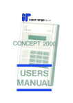
Download Code Alarm 2000 User`s manual
Transcript
This page intentionally left blank
CONCEPT 2000 USER'S MANUAL
TABLE OF CONTENTS
Basic Concepts ............................................................................................................................................................3
AREA......................................................................................................................................................................3
USERS ....................................................................................................................................................................3
ZONES....................................................................................................................................................................3
ON And OFF ...........................................................................................................................................................4
TERMINAL.............................................................................................................................................................4
Description Of The Keys..............................................................................................................................................5
Operating your System.................................................................................................................................................7
3.1 Turning An Area On Or Off...............................................................................................................................7
3.2 Multiple Area User.............................................................................................................................................7
3.3 Isolating Zones On Exit .....................................................................................................................................8
3.4 Turning On/Off More Than One Area................................................................................................................8
3.5 SPECIAL AREAS - AREA 0 AND AREA 9.....................................................................................................8
3.6 ACKNOWLEDGING ALARM MESSAGES ....................................................................................................9
3.7 TURNING OFF SIRENS ...................................................................................................................................9
IMPORTANT; THE SYSTEM HAS NOT BEEN TURNED OFF. .......................................................................9
OTHER PANEL OPERATIONS................................................................................................................................10
4.1 MENU .............................................................................................................................................................10
REVIEW MEMORY .................................................................................................................................................11
5.1 SEARCHING FOR AN EVENT IN REVIEW.................................................................................................12
5.2 REVIEW MEMORY SIZE...............................................................................................................................12
5.3 CONDENSED MODE .....................................................................................................................................12
CHANGE CODES.....................................................................................................................................................13
6.1 User 999 - The Master User .............................................................................................................................16
6.2 USER 001 - THE INSTALLER........................................................................................................................16
6.3 DIS-ABLE USER 001......................................................................................................................................16
ISOLATE ZONE/INPUT ...........................................................................................................................................17
WALK-TESTING AREAS ........................................................................................................................................19
8.1 SINGLE AREA USER.....................................................................................................................................19
8.2 MULTIPLE AREA USERS..............................................................................................................................19
ADJUSTING THE TIME AND DATE. .....................................................................................................................20
9.1 CLOCK CORRECTION .................................................................................................................................20
USING THE DEADMAN TIMERS...........................................................................................................................21
PROGRAMMING .....................................................................................................................................................22
11.1 REMOTE SERVICE DIAGNOSTICS............................................................................................................22
CALL-BACK.........................................................................................................................................................23
ACCESS CONTROL.................................................................................................................................................24
13.1 OPERATING DOOR-LOCKS........................................................................................................................24
The electric lock will only operate if:- ................................................................................................................24
GLOSSARY OF ERROR MESSAGES......................................................................................................................25
PART SPECIFICATIONS .........................................................................................................................................27
Control Module..................................................................................................................................................27
DISPLAY & KEYS............................................................................................................................................27
USER CODES ...................................................................................................................................................27
ZONES ..............................................................................................................................................................27
C2000 User Manual
Page 1 of 28
This page intentionally left blank
C2000 User Manual
Page 2 of 28
Basic Concepts
To use the Concept 2000 system effectively it is helpful to understand six simple terms used in the system. These six
terms are:
•
•
•
•
•
•
Areas
Users
Zones
On
Off
Terminals
AREA
The Concept 2000 security system is designed to protect one or more areas. When you wish the Concept 2000 to
protect an area, then you need to turn that area on. When protection is no longer required for an area then you need to
turn that area off.
The areas protected by the Concept 2000 system all have names so that you can recognize what they are. These names
can be chosen by you so that you can easily recognize the area you are protecting.
Examples of area names are:
FRANKS SHED
E.D.P. CENTER
OFFICE
HOUSE AND GARAGE
WAREHOUSE ADMINISTRATION
USERS
The Concept 2000 can be operated by one or more persons who are called users.
All users, who are allowed to operate your Concept 2000 , have names so that the Concept 2000 can recognize who is
using the system. These names can be chosen by you so that you can easily recognize what user you are referring to.
Examples of user names are:
FRANK THRING
SALLY FIELDS
ALAN BOND
ZONES
The Concept 2000 protects an Area with special alarm detectors called Zones.
These alarm detectors are designed to register un-authorized movement in the protected Area.
The Zones all have names, chosen by you, so that you can recognize which Zone is which.
Example of Zone names are :FAMILY ROOM SLIDING DOOR
COMPUTER ROOM PIR
FRANKS SHED WINDOW
REAR FIRE EXIT DOOR
LIFT LOBBY PIR
C2000 User Manual
Page 3 of 28
ON And OFF
The most common operation performed on the Concept 2000 is a User (eg. FRANK THRING )
turning an Area ( eg. FRANKS SHED) either On to protect the Area, or Off to access the Area.
Each Area ( eg. FRANKS SHED) may have one or more Zones ( eg. FRANKS SHED WINDOW)
used to protect that Area when the Area is turned On.
TERMINAL
All Concept 2000 operations, such as turning On and Off Areas, are carried out at a Terminal.
The Concept 2000 may have up to eight (8) Terminals connected and any Terminal may be used to operate the
system.
A terminal is referred to in two parts, the keypad which is used to enter your User code and operate the system and a
display window, immediately above the keypad, which is used to display messages from the system to the User.
The first step in using a Terminal is to enter your own secret code using the digit keys on the keypad, and then
pressing the OK key. The Concept 2000 will now work out who you are and greet you by displaying your name in the
display window.
After a few seconds the Concept 2000 will now display the name of the Area that you are allowed to turn On or Off.
The display window is used to tell you what the system is doing. Sometimes the message to be displayed is larger than
will fit in the display window. If this occurs, the message will automatically scroll slowly to the left so that you can
read it.
An important feature of the Concept 2000 panel is the use of the HELP key. When the HELP key is pressed, the
Concept 2000 panel will display a “ help message” on the panel operation you are currently performing.
If you are not sure what to do next, when using the Concept 2000, then press the HELP key.
C2000 User Manual
Page 4 of 28
Description Of The Keys
The Concept 2000 is controlled by using the keypad located below the display window.
Each time a key is pressed the Concept 2000 will emit a short “beep” to indicate that the key was accepted.
You may press the keys as fast as you like but, only one key should be pressed at a time.
If the Concept 2000 emits a “long beep” when a key is pressed it means that the key was not accepted or is not
allowed.
The keypad has 20 keys, all of which are listed below with a brief explanation of their purpose,
The HELP key is used to display a “help message”, on the current operation being performed, by the user. The HELP
key can be pressed at any time. If no help is available on the current item then the display window will not alter. When
you have finished looking at the “help message”, press any digit key.
The digit keys are used for entering your secret code before using the Concept 2000. When entering your secret code,
you have 15 seconds to press each digit. When you have entered all of the digits of your secret code, you must press the
OK key. No Concept 2000 panel operations can be carried out until you have entered your secret code and pushed the
OK key.
Each key has letters associated letters with the digits. By using familiar words, these letters can be used to help you
remember your secret code.
For example; the word “FRANK” could be used to help you remember the secret code comprising of the digits “2”,
“6”, “1”, “5” and “4”
The OK key is pressed after you have entered your secret code. You have 15 seconds to press the OK key once you
have completed entering your secret code. Pressing the OK key tells the Concept 2000 to check the secret code you
have just entered.
The END key is used when you have finished using the Concept 2000 panel, or if you make a mistake whilst entering
your secret code. Once the END key is pushed, you must enter your secret code again.
During normal operations, if the Concept 2000 detects no key presses for more than 15 seconds, then the Concept
2000 will automatically “press” the END key and you will have to re-enter your secret code again.
The ON key is used to turn On the Area whose name is being displayed in the display window.
The OFF key is used to turn Off the Area whose name is being displayed in the display window.
The MENU key is used if you wish to perform other Concept 2000 operations apart from turning Areas On or Off.
(Of course you must have already entered your secret code plus the OK key.)
When the MENU key is pushed, the Concept 2000 will list, in the display window, the other operations you are
allowed to perform.
The MENU key is not used during normal operation. If you press it by accident then press the “O” key or the END
key.
C2000 User Manual
Page 5 of 28
The LEFT and RIGHT arrow keys are optionally used during normal operations to control scrolling messages in the
display window. Each time the LEFT arrow is pushed, the scrolling message will start again from the beginning. If the
scrolling is too fast, or too slow, use the RIGHT arrow to step the message one letter at a time, or, hold down the
RIGHT arrow to speed up the scrolling message. Most scrolling messages will scroll 3 times.
You do not need to use these keys during scrolling messages if you do not want to. The speed of scrolling messages is
set to your reading rate and when the scrolling message reaches the end it will start again, from the beginning
automatically.
The UP and DOWN arrow keys are normally used by persons who are allowed to turn On or off more than one Area.
If the Area name in the display window is not the Area you wish to turn On or Off then, pressing the UP or DOWN
arrows repeatedly, the display window will show the names of all Areas that this User is allowed to operate.
The UP and DOWN arrow keys are also used in other Concept 2000 panel operations such as Review and Change
Codes.
C2000 User Manual
Page 6 of 28
Operating your System
3.1 Turning An Area On Or Off
The most common operation of the Concept 2000 panel is turning On or Off Areas. To turn On or Off an Area you
must first enter your secret code then press the OK key.
As the digits of your secret code are entered the display window will show each digit as a “#” character:
If you make a mistake, press the END key and start again.
After the OK key is pressed, the Concept 2000 will work out who you are and will display a short greeting message
such as:
After a few seconds, the Concept 2000 will work out and display which Area you would normally turn On and Off and
whether that Area is currently On or Off.
For example:
You may now press either the ON key to turn the Area On, or the OFF key to turn the Area Off.
If you do not wish to turn the Area On or Off, you may finish panel operations by pressing the END key, or you may
press the MENU key to perform other panel operations. (See “Other panel Operations”)
Some Users may be allowed to control more than one Area. If you can control more than one Area, and the Area name
shown on the display is not the Area you wish to control, then by pressing the up or DOWN arrow keys, the Concept
2000 will display all of the Area you are allowed to turn On or Off.
Alternatively, if you know the Area number you wish to operate, simply press the number of the Area you wish to
control.
When the Area being shown is correct, you may press the ON key or the OFF key to turn On or Off that Area.
3.2 Multiple Area User
Some Users may be asked which Area they wish to operate and the display window will show:
The second line of the display window will show all the Areas that you are allowed to turn On or Off. Simply press the
number of the Area you wish to operate.
When an Area is turned On, the Concept 2000 will first check all of the Zones that are used to protect that Area and
see that they are currently ready to be armed. (Sealed) If there is a problem with any Zone, the Concept 2000 will
display the name of the faulty Zone so that the User may go and rectify the problem.
• For example; if “FRANKS SHED WINDOW’ was open when “FRANK THRING” went to turn On “FRANKS
SHED”, then the Concept 2000 would display the following message:
“FRANKS SHED WINDOW is un-sealed. Please secure zone and press ON or press END”
FRANK THRING must go and shut the window and then try again by pressing ON. If FRANK took too long in
shutting the window, he may have to start again by re-entering his User code.
C2000 User Manual
Page 7 of 28
3.3 Isolating Zones On Exit
Some Users may be allowed to Isolate the un-sealed Zone which will then prevent the Zone from detecting movement
for the period that the Area is turned On.
If FRANK THRING was allowed to Isolate Zones then the display would show:
n “FRANKS SHED WINDOW is un-sealed. Please secure zone and press ON or isolate this zone by pressing OK.
Press END to abort”
FRANK THRING may go and shut the window and then try again by pressing ON or FRANK can Isolate FRANKS
SHED WINDOW by pressing the OK key.
3.4 Turning On/Off More Than One Area
Some Users, who can operate more than one Area, may wish to turn On or Off all their Areas at once. This can be
done by pushing the LEFT or RIGHT arrow keys when an Area is being displayed.
The display window will now show:
By pressing the ON key, all Areas you are allowed to control will automatically turn On, one by one, if they are Off.
By pressing the OFF key, all Areas you are allowed to control will automatically turn Off, one by one, if they are On.
If some of the Areas are already Off or On, then the Terminal will “beep” and the display window will show that the
“Area is already Off”, or, the “Area is already On”.
3.5 SPECIAL AREAS - AREA 0 AND AREA 9
The Concept 2000 has ten (10) Areas which may all be turned both On and Off. These Areas are numbered from 0 to
9 and all have names so that you can easily recognize which Areas they are.
Area 0 and Area 9 are two special Areas that are normally turned On at all times.
Area 0 is often named “TAMPER AREA” whilst Area 9 is often named “SYSTEM AREA”. Both of these Areas are
used to protect the Concept 2000 from any un-authorized tampering.
If an alarm occurs in Area 0 or Area 9, then the Area may be turned Off to silence the sirens if they are sounding. If
sirens are not sounding, then you needn’t turn Off the Area but rather just acknowledge the Alarm. (See
“Acknowledging alarms” )
A User must be able to control Area 0 and Area 9 before “Tamper Area” or “System Area” alarms can be
acknowledged.
You must remember to turn Area 0 and Area 9 back On. If they are not turned On, the Concept 2000 will be
vulnerable to tampering and SYSTEM SECURITY WILL BE SEVERELY COMPROMISED.
When turning on Area 0 or Area 9, any problems will be displayed if they are present.
DO NOT TURN ON AREA 0 OR AREA 9 IF A PROBLEM IS DISPLAYED, WITHOUT FIRST RECTIFYING THE
PROBLEM.
• Note: If the OK key is pressed, when a problem is displayed, you will cause an alarm immediately which may
sound the sirens.
C2000 User Manual
Page 8 of 28
3.6 ACKNOWLEDGING ALARM MESSAGES
When an alarm occurs in an Area which is turned On, the Concept 2000 will often display an alarm message on the
Terminal. The alarm message will identify the name of the Zone which caused the alarm and the name of the Area
that contains the alarmed Zone.
The alarm message will be continuously displayed, in the display window, until the alarm message has been
acknowledged by a User.
Any User can acknowledge the alarm message as long as that User can control the Area in which the alarm occurred.
The User simply enters their secret code and then presses the OK key to acknowledge the alarm.
The User will often want to turn the Area Off so that he/she can gain access. Because you need to enter your secret
code and press OK before you can turn the Area Off, any alarm messages for that Area will be automatically
acknowledged.
If more than one alarm occurs in a single Area, only the last Alarm is displayed.
If alarms occur in more than one Area, then each alarm needs to be acknowledged separately.
3.7 TURNING OFF SIRENS
If an alarm occurs in an Area that is programmed to sound the sirens, the sirens will sound for 10 minutes (or the
time set by the Installer) before turning Off automatically. The sirens can be turned Off earlier by any User simply
entering their secret code and pressing the OK key as long as that User is allowed to operate the Area which caused
the sirens to sound.
IMPORTANT; THE SYSTEM HAS NOT BEEN TURNED OFF.
YOU HAVE ONLY TURNED THE SIRENS OFF. IF ANOTHER ALARM OCCURS THEN THE SIRENS WILL
OPERATE AGAIN. YOU MUST TURN THE AREA WHICH CAUSED THE ALARM OFF TO PREVENT
FURTHER SIREN ACTIVATIONS.
C2000 User Manual
Page 9 of 28
OTHER PANEL OPERATIONS
When your secret code is entered and the OK key is pushed, the Concept 2000 assumes that you wish to turn On or Off
an Area. Sometimes you may wish to perform some other panel operation.
4.1 MENU
To perform another panel operation, other than turning On or Off Areas, you must press the MENU key first.
When the MENU key is pushed, the Concept 2000 will display what other operations you are allowed to perform. The
operations available may be different from User to User.
Listed below are all of the possible panel operations available other than the turning On and Off of Areas:
• 0 AREA ON/OFF
This option will return the User from the Menu options back to Area On/Off operations.
• 1 REVIEW PAST EVENTS.
This option is used to inspect the Concept 2000 memory to see, for example, what alarms have occurred or who has
been turning On or Off Areas.
• 2 CHANGE CODES.
This option is used to alter or delete existing User codes in the Concept 2000 system or to add new User codes.
• 3 ISOLATE ZONES
This option allows individual Zones in the Concept 2000 system to be isolated prior to turning On an Area.
• 4 WALK-TEST AN AREA
This option allows a User to Walk-test an Area so as to check the operation of all Zones within the system.
• 5 SET TIME AND DATE.
This option allows the User to set the Time and the Date for the Concept 2000 system.
• 6 ENABLE DEADMAN.
This option allows the User to turn on and off the Deadman feature. (See “Using the Deadman facility”)
• 7 PROGRAMMING.
This facility is not used in the day to day operations of the Concept 2000 system and is only accessible by the Installer
during the programming of the system.
• 8 MENU CALL-BACK.
This will cause the Concept 2000 to dial the pre-programmed Call-Back number used to contact the Installer’s Service
Center. Only use this option when instructed by the Installer. Only the Master User or Installer can operate this option.
*Note: You may go back to turning On or Off Areas by pressing the “0” key.
C2000 User Manual
Page 10 of 28
REVIEW MEMORY
Review is used to inspect what your system has been up to while you were not using it.
After pressing the MENU key, press the “1” key.
The display window will now show the last item which was entered in the review memory. The first line will show the
date and time, to the nearest second, that the event occurred. The second line will show the actual event and will often
be scrolling.
Use the UP arrow to go backwards through review memory and inspect earlier events. One key- press of the UP arrow
is one review event.
Use the DOWN arrow to go forward through review memory and inspect more recent events. One key -press of the
DOWN arrow is one review event.
The LEFT and RIGHT arrows can be used to control the scrolling if you wish.
Each time the LEFT arrow is pushed, the scrolling message will start again from the beginning.
If the scrolling is too fast, or too slow, use the RIGHT arrow to step the message one letter at a time, or hold down the
RIGHT arrow to speed up the scrolling message.
When you are finished using the Review facility, press the END key if you are finished using the Concept 2000, or
press the MENU key to perform another Concept 2000 function.
*Note: At any time the user may press HELP for help on review.
C2000 User Manual
Page 11 of 28
5.1 SEARCHING FOR AN EVENT IN REVIEW
Sometimes you may wish to find a particular review event that may have occurred many days ago. To save looking at
all review events, which may have occurred after the particular event you are looking for, the Concept 2000 can
automatically search for a particular event.
The digit keys from “0” to “8” can be pressed to search backwards through review memory for specific items. Each
time a digit key is pressed the review memory is searched backwards for that item. If the item is not the desired one
then press the same digit key again to resume searching for the next event.
When the start of review is reached, press the “8” key to go to the end of review so you can search backwards again if
you wish.
The possible search items are:
0 …… Jump to the first Review item saved. (Start of review)
1 ……. Search for he last Alarm or Restore which occurred.
2 ……. Search for the last Isolate of a Zone.
3 ……. Search for the last User to log on to a terminal.
4 ……. Search for the last time Sirens turned on or off
5 ……. Search for the time an Auxiliary turned on or off.
6 ……. Search for the last lock operation.
7 ……. Search for other Miscellaneous items.
8 ……. Jump to the last Review item saved. (End of review)
5.2 REVIEW MEMORY SIZE
Pressing the “9” key will cause the Concept 2000 to display how many items the review memory can hold.
The number of items it can hold depends on the number of User codes and the number of Zones in the system. When
the review memory fills the oldest event will be forgotten, on an event by event basis, each time a new event is saved.
5.3 CONDENSED MODE
When skipping through Review, searching for certain events, it may be convenient to have the Review information
condensed so that it is easy to read. If the OK key is pushed whilst you are in Review, then the Review format, in the
display window, will be condensed with no scrolling messages.
Pressing the OK key a second time will cause the normal Review format to be displayed.
C2000 User Manual
Page 12 of 28
CHANGE CODES
All Users who are allowed to operate your Concept 2000 panel are issued numbers from000 to 016.
• Note: Some systems may allow up to 96 Users and others to 512.
Each User has their own name and their own secret code. One of the Users has to be given the responsibility of setting
up and making the required changes to User codes.
The User with this responsibility is User 000 and is referred to as the MASTER USER.
When User 000 presses the MENU key, one of the options available to him/her is:“2 = Change Codes”
If Users are to be altered, or more Users added, then User 000 selects this option.
When Change Codes is first entered, the display window shows:
Either enter the specific User number to alter, using the digit keys, or press the OK key to proceed with the displayed
User number.
•
•
•
•
For the following options, pressing the OK key will advance to the next question
Pressing the LEFT arrow will go back to the previous question.
Pressing the UP or DOWN arrows will display the current question for other User numbers.
For Yes/No questions, press the “9” key for “Yes” and any other digit key for “No”.
• Note: A “No” is displayed as a “Blank”.
After selecting a User number to inspect or alter, the first item to enter is the User’s name.
This option allows the User’s name to be inspected or altered. The digit keys and the LEFT & RIGHT arrows can be
used to alter the displayed name.
• Note: The example used is User 002.
To select a letter, press the appropriate digit key where the desired letter appears. Press this key repeatedly until the
correct letter is displayed. Press the RIGHT arrow to advance to the next letter or the LEFT arrow to go back to the
previous letter.
•
•
•
•
Pressing the OFF key clears the display.
Pressing the ON key clears the display to the right of the cursor.
A “space” is located with “9” key.
Miscellaneous punctuation is located with the “0” key.
C2000 User Manual
Page 13 of 28
The secret code may now be entered for this User number.
All digits “0” to “9” are allowed and the secret code may be 1 to 8 digits in length.
• Note: the actual numbers contained in the secret code are only displayed if you are inspecting or altering your won
code. If you are not altering your own secret code the numbers are displayed as “#”. This allows individual Users to
keep their secret code private from User 000.
This option determines which of the Concept 2000’s eight Areas this User number is allowed to control.
• Note: User 000 is also allowed to control Area 0 and Area 9. (See “Special areas - Area 0 and Area 9”)
This option determines if this User is allowed to Isolate Zones, which belong to the Areas controlled by this User. This
option only applies to the “Isolate zones” option in the MENU.
• Note: This question is not asked for User 000.
This option determines whether this User is allowed to inspect Review memory and scroll through the review events.
• Note: This question not asked for User 000
All Users may turn On Areas that they are allowed to control. This option allows some Users to turn Areas On but not
Off.
• Note: This question is not asked for User 000.
If programmed “Y”, then this User can turn On the Deadman alarm feature. (See “Using the Deadman facility”)
• Note: This question not asked for User 000.
Normally, only User 000, the Master User, is allowed to alter or issue other User codes, however, other responsible
Users may also be allowed to perform this function if this option is programmed “Y”.
Other Users given this privilege may never alter User 000 or User 001.
• This question not asked for User 000.
The Concept 2000 has two special Areas called Area 0 and Area 9. Answering “Y” to this option allows this User to
operate these special Areas. (See “Special Areas- Area 0 and Area 9”)
• Note: This question not asked for User 000.
C2000 User Manual
Page 14 of 28
When a User attempts to turn On an Area, any un-sealed Zones in the Area will be displayed in the display window. If
this option is “Y”, then this User may Isolate any un-sealed Zones by pressing the OK key.
If this option is set to “N”, then the Area with the un-sealed Zones cannot be turned On by this User until the
offending Zones are secured.
• Note: This question not asked for User 000
This option determines whether this User is allowed to perform Walk-testing of Areas under his/her control. (See
“Walk-testing an Area”)
• Note: This question not asked for User 000
Your Concept 2000 may have been configured to include up to 5 different time zones which may b employed to
prevent certain Users from using the system outside the times specified by the time zones.
If a “Y” appears under one of the five time zone digits, then this User code will only operate during the hours
programmed to that time zone.
A User may be associated with more than one time zone. When more than one time zone is selected, then the User
code will operate during any of the time zones specified. Check with your Installer as to whether time zones have been
set up.
For example:
Time zone #1 - 09:00 AM to 17:00 PM, Mondays to Fridays.
Time zone #2 - 10:00 AM to 13:00 PM, Saturdays only.
• Note: This question not asked for User 000.
This option is normally set to “Y”. This will cause the Concept 2000 to assume that the Area you wish to turn On or
Off is the Area that you would commonly operate from the Terminal at which you are standing and where you have
just entered your secret code.
Your Installer will set up what common Areas relate to each Terminal location.
If this User is only allowed to un-lock doors and not allowed to turn On or Off Areas, then answer “Y” to this
question. (See “Operating door-locks”)
• Note: This question not asked for User 000
This option has been set aside for future expansion of the Concept 2000. Leave this option set to “N”.
• Note: This question not asked for User 000
Any User number, with the exception of User 000, may be defined as a Duress code. A Duress code works identically
to a normal User code, with the exception that a Duress alarm is raised, which may optionally contact a Central
Station. Every User may have their own Duress code, or alternatively, a few User codes may be set aside as common
Duress codes.
• For example: 999,00000,11444, or something less obvious.
• Note: This question not asked for User 000
C2000 User Manual
Page 15 of 28
When the Concept 2000 needs to display more than one screen of information, the second line of the display window
is scrolled. The scrolling may always be controlled by, pressing the LEFT arrow to re-start scrolling, or the RIGHT
arrow to scroll letter by letter. Holding the RIGHT arrow pressed will speed up the scrolling.
This option allows the default scrolling rate to alter depending on the current User operating the system. Scrolling
speed may be set between 1 and 8 characters a second. A good average to choose is 5 to 7 chars/sec.
6.1 User 999 - The Master User
User 999 is the most powerful User in the system. He/she can perform any panel operation except Concept 2000
programming. The secret code of User 000 is the single most important code in the system and must be treated as if it
were the combination to a vault.
DO NOT LOSE OR FORGET THE MASTER CODE.
6.2 USER 001 - THE INSTALLER
Programming of the Concept 2000 can only be performed by User 001. User 001 is normally assigned to the Installing
Company. User 000 cannot alter User 001 code options. Like-wise, User 001 cannot any other User code options
although can access Programming options ect.
6.3 DIS-ABLE USER 001
After the completion of the Concept 2000 installation, setting this option to “Y” prevents the Installer from accessing
system both locally and via the telephone line, (except if the system is monitored). If User 001 ( normally the Installer
) wishes to alter your system, he/she must first ask the Master User to set the above option to “N”.
C2000 User Manual
Page 16 of 28
ISOLATE ZONE/INPUT
Certain Users may be allowed to Isolate Zones via the Concept 2000 ‘s MENU options
• Note: To Isolate a Zone the Area(s) which that Zone is in, must be OFF.
When a Zone is Isolated and the Area containing that Zone is turned On, the Zone will be ignored for the rest of the
time that the Area remains On. When the Area is turned OFF again, the Isolated Zone will automatically be reinstalled and no longer be ignored.
The opposite for a Zone being Isolated is for the Zone to be Enabled.
The normal operating condition is for all Zones to be Enabled so that when an Area is turned ON, the Zones
belonging to that Area will operate.
Isolating Zones using this method is designed as a temporary fix to a problem only.
• For example: If a detector has been accidentally knocked off a wall, that Zone may be Isolated prior to it being
fixed.
To Isolate a Zone, press the MENU key followed by the “3” key.
The display window will show:
Select the number of the Zone that you wish to Isolate, by using the digit keys, and then pressing the OK key.
The display window may show:
or
The first line, of the display window, shows whether that Zone is currently Enabled (normal setting) or is currently
Isolated.
The second line, of the display window, shows the name of the selected Zone.
If the Zone is Enabled you may Isolate it by pressing the OFF key.
If the Zone is Isolated you may Enable it by pressing the ON key.
Often, the User will only know the name of the Zone to be Isolated or Enabled. By using the UP or DOWN arrows, the
names of all the Zones can be quickly checked until the right Zone name appears on the second line.
Pushing the OK key will prompt the User for another Zone number.
C2000 User Manual
Page 17 of 28
When you are finished, press either the MENU key or the END key.
User 000 will be asked a preliminary question after the MENU and “3” keys are pushed.
Press the “1” key.
The “2” key should only be used under instruction from your Installing company.
C2000 User Manual
Page 18 of 28
WALK-TESTING AREAS
It is prudent to regularly check that all Zones within an Area are fully operational, Some Insurance requirements insist
that this type of test is performed on a regular monthly basis.
8.1 SINGLE AREA USER
All Zones within an Area can be checked when the Area is OFF by pressing the MENU key, then the “4” key.
The display window will show the mane of the Area being tested.
For example: The display window may show:
The User now walks around the Area (FRANKS SHED) and deliberately alarms every Zone used to protect that Area.
As each Zone is alarmed, the Terminal will emit a short “beep”. You may take as long as you like to Walk-test an
Area.
When all Zones have been alarmed, the User now presses any digit key on the key-pad.
If all Zones protecting that Area have operated correctly, the display window will show:
The User may now either press MENU, to select another Concept 2000 operation, or press END if finished with the
Concept 2000.
If one or more Zones were not alarmed whilst Walk-testing the Area, the display window will show:
The User may now repeatedly press any digit key to display the names of all Zones that failed the Walk-test.
When the failed Zone(s) have been identified, press the OK key to resume Walk-testing and proceed to alarm the
Zone(s) that failed the first time.
On return to the T4erminal, again press any digit key to see if the Walk-test passed.
When you are finished Walk-testing, whether the test passed or failed, press the END key or the MENU key.
8.2 MULTIPLE AREA USERS
Some Users are allowed to Walk-test more than one Area. These User will be asked which Area they wish to test proir
to the start of the Walk-test’
The second line, of the display window, will list all the Areas which may be Walk-tested by this User.
Simply press a digit key corresponding to the Area you wish to test and follow the same procedures listed for a single
Area User
C2000 User Manual
Page 19 of 28
ADJUSTING THE TIME AND DATE.
The Concept 2000’s Time and Date can be set by the Master User. Some Central Stations will automatically perform
this task for you when the system is monitored.
First press the MENU key, followed by the “5” key.
• Note: Only User 000 may perform this function.
The display window will show:
The second line shows the time, to the nearest minute, when Set time/date was entered.
By using the LEFT arrow, the RIGHT arrow and the digit keys, the time and date may be adjusted to the correct
settings.
Now press the OK key to save the new time and date.
At the instant the OK key is pushed, the seconds are set to zero and the Concept 2000 automatically returns the User
to the menu.
9.1 CLOCK CORRECTION
Sometimes, the Concept 2000 clock maybe running slightly fast or slightly slow.
The clock can be corrected by pressing the UP or DOWN arrow keys when setting the time and date.
The display window will now show:
The current clock correction can be adjusted by repeatedly pressing the UP or DOWN arrow keys to achieve the
desired amount of seconds.
.
• For example: If the clock is running fast by 10 seconds per week then adjust the current
clock correction down by 10 seconds a week. (-10 s
• If the clock is running slow by 10 seconds per week then adjust the current clock
correction up by 10 seconds a week. (+ 10 secs)
When the clock corr4ection has been adjusted, press the LEFT or RIGHT arrow keys to go back to the set time and
date display.
C2000 User Manual
Page 20 of 28
USING THE DEADMAN TIMERS
The Deadman facility is used so the Concept 2000 system can “keep an eye” on personnel working in the vicinity of a
Concept 2000 Terminal.
The Deadman facility can either be enabled or dis-enabled, on a per terminal basis, by first pressing MENU, followed
by the “6” key.
The display window will show:
The User may now select which Terminal(s) in the Concept 2000 system will have the Deadman facility enabled by
placing a “Y” under the respective Terminal number
If no Deadman facility is required, then set all Terminals to “N”.
When the Deadman facility has been enabled for one or more Terminals, those Terminals will act as follows:
• If the Terminals with Deadman enabled do not have had a valid User. code entered for at least 30 minutes, all
Terminals, with the Deadman
facility enabled, will continuously “beep” and display the message:
If a valid User code is not entered at any of the Deadman Terminals within 60 seconds, a Deadman alarm will be
raised which may optionally report to a Central Station.
• Note: The 30 minute time, referred to above, is programmed by your Installer to be any
time period between 1 minute and 4 hours, 15 minutes.
C2000 User Manual
Page 21 of 28
PROGRAMMING
The Concept 2000 is an extremely powerful system that will be fulfilling security needs well into the 21st Century.
This versatility is the result of thousands of programming options available throughout the Concept 2000 system and,
as a result, this module is usually restricted for use by the Installer only.
The Installer, User 001, has the same system access levels as the Master User, User 000, and has the added feature of
being able to program the system.
It is strongly recommended that, once the Installation has been completed, the Master User prevents any further
unauthorized changes to the programming by “locking Out” User 001. (See “Dis-able User 001”)
If your Installer is required to make any authorized changes to programming, the Master User must enable User 001
before the Installer can gain access to the system.
11.1 REMOTE SERVICE DIAGNOSTICS
The Installer may service and program your Concept 2000 over the telephone line by dialing into the system. This is a
very powerful service diagnostics facility.
When User 001 is dis-abled, remote service over the telephone line cannot be performed.
Again, the Master User would have to enable User 001 before any remote programming can be effected.
C2000 User Manual
Page 22 of 28
CALL-BACK
The Concept 2000 system stores several telephone numbers in its memory that are programmed by the Installer. These
telephone numbers are used, by the Concept 2000, to communicate alarms to Central Stations or to Private telephone
numbers.
It is recommended that the Concept 2000 always be connected to the telephone line so that Remote service diagnostics
may be effected.
The system is designed to be connected to an “external” telephone line so that the Concept 2000 may be dialed
directly. Sometimes, this is not possible and the system is connected to an extension from a switchboard.
In other circumstances, the system is connected to the same telephone line as a facsimile machine.
In both cases, the Concept 2000 can make outward calls without difficulty, however, there may be problems with the
Concept 2000 answering incoming calls when Remote service diagnostics are required.
The switchboard extension may not have “indial” capabilities, (You cannot ring directly to the extension.) and both
the facsimile machine may be programmed to answe4 the phone after the very first ring. Both of these circumstances
will prevent the Concept 2000 from answering the telephone.
By pressing the MENU key, followed by the “*” key, the Concept 2000 will automatically call the pre-programmed
Call-back number and establish communications with the Installer’s service center.
DO NOT USE THIS FEATURE UNLESS INSTRUCTED BY YOUR INSTALLER.
C2000 User Manual
Page 23 of 28
ACCESS CONTROL
13.1 OPERATING DOOR-LOCKS
Concept 2000 Terminals may be installed to control electrically operated door locks. Your alarm Installer can advise
you on the full Access Control capabilities of the system.
The electric door lock is operated by pressing the OK key a second time, when the Concept 2000 Terminal is displayed
an Area name to turn On or Off.
The electric lock will only operate if:•
•
•
•
The Area the lock provides access to is currently turned Off.
The User is allowed to control that Area.
The User is using the Terminal next to lock.
The User is within the permitted Time Zone(s), (See “User Codes”)
If a User is defined as a “Lock only user” (See “User codes”), then the OK key does not have to be pushed a second
time.
When the electric lock operates, the display window will show the following message for 5 seconds:-
If the electric lock is allowed to operate at this time, the display window will show the following message for 5
seconds:Whether the electric lock operates or not, you must enter your secret code again if you wish to perform other panel
operations.
C2000 User Manual
Page 24 of 28
GLOSSARY OF ERROR MESSAGES
Below, is a glossary of common error messages that can occur in the Concept 2000 system:
“User dis-abled. Memory not configured to store this User. Memory must be re-configured by Installer.”
• A User number was selected that the Concept 2000 has not been allocated memory space to save.
The Installer must use the Code configuration option to allocate more memory.
“Code duplication. This code erased”
• When entering a new secret code for a User, a code was chosen that is already being used. You must choose
another code not used by any other User.
“Incorrect code. Please try again”
• A User was entered that was not recognized by the Concept 2000.
“Enter your code to prevent alarm”
• The Terminal that this message appears on has been set for Deadman operation. Any valid User code must be
entered at this Terminal to prevent a Deadman alarm.
“Installer code dis-abled”
• The Installer (User 001), has entered their code, but User 000 has dis-abled the code using the “Dis-able User
001” option in “User codes”.
“Access denied. Time violation”
• A legal User code has been entered but this code has been set to only operate during certain time zones. (See
“Time Zones” in “Change Codes”)
“Too many tries. Wait 60 seconds.”
• Too many illegal User codes were entered. The Terminal will not recognize any key presses for 1 minute.
“Area 9 is Off”
• Area 9 (SYSTEM AREA) is currently Off. Area 9 should normally be turned On at all times.
“Area 0 is Off”
• Area 0 (TAMPER AREA) is currently Off. Area 0 should normally be On at all times.
“Power has failed to Control unit”
• A.C. power to the main Concept 2000 Control unit is not connected, or has been turned Off.
“Power has failed to Remote unit”
• A.C. power to a Remote unit is not connected, or has been turned Off.
“Battery is low in Control unit”
• The main Control unit internal back-up Battery is low. Less than 30 minutes remain before the Concept 2000
will totally shut-down.
“Battery is low in Remote unit”
• A Remote unit internal back-up Battery is low. Less than 30 minutes remain before the remote unit will not
function.
“-Warning - Lost module”
• The Concept 2000 has ceased communicating with a Terminal or Zone Expansion card due to problems. The
Installer must be called to rectify the problem.
“Can’t walk-test. Area must be Off.”
C2000 User Manual
Page 25 of 28
• The Walk-testing of an Area was attempted without turning the Area Off first.
“Zone/Input does not exist”
• A Zone was chosen in Isolate mode that does not exist.
“Zone/Input must be Off by Areas”
• An attempt was made to Isolate or Enable a Zone, whilst at least one or more Areas which use that Zone are
On. All Areas using that Zone, including Area 0, must be Off to Isolate or Enable that Zone.
“Area dis-abled for this code”
• A User has attempted to operate an Area which he/she is not allowed to operate.
“(Area Name) is held off”
• A User has attempted to turn On an Area which is also controlled by another Area which is currently Off. This
can occur when the Installer has set up Areas to be turned On automatically by other Areas rather than be
Users.
“(Area Name) is ON. You are not allowed to access this Area.”
• A User code has been entered that can only turn Areas On and the Area being viewed is currently On.
“(Area Name) has been turned Off by another User.”
• After just turning an Area On and at the end of exit delay, the Concept 2000 has discovered that this same Area
has been turned Off by another User at another Terminal.
“Can’t use Area. Area being used.”
• A User has tried to use an Area that is permitted for use, but the Area is currently being used by another User at
another Terminal. Only one User can operate an Area at a time.
“The ON key has been dis-abled”
• The ON key has been dis-abled by the Central Station.
“No lock for this User”
• A User has attempted to un-lock a door and is not allowed to do so. Either the User is not permitted access to
this Area or the Area protected by the lock is still On.
C2000 User Manual
Page 26 of 28
PART SPECIFICATIONS
Control Module
Dimensions
Length
Width
Height
Maximum ambient temperature
Lid Tamper protection
Chassis Tamper protection
Chassis orientation
Fabrication material
415mm
210mm
73mm
50 degs C
YES
YES
ANY
Mild steel
DISPLAY & KEYS
Display types
Scrolling rate
Terminals beeper warnings
Number of keys
Maximum code entry speed
Terminal dimensions
Flush
Surface
User character set
EL Backlit
32 Character
2x16 line
LCD
1-8 Chars/sec
0.1 second
1.0 second
Continuous
20
10 keys/second
185x120x10
185x120x31
A to Z capitals
0 to 9 digits
# & ‘ () * + , - ./
:;<=>?@
space
Pulse count Zones
No. of pulses
Pulse timer
YES
2.3 or 4
10-255 seconds
AREAS
Area name length
No. of individual arming areas
Zones per area
Area overlap allowed
Exit delay per area
Entry delay per area
No. of primary zones per area
Siren time per area
Siren time accuracy
16 characters
10
0 to 96
YES
0-99 seconds
0-99 seconds
6
0-99 minutes
1 second
SIRENS
Peak current for internal sirens
Peak current for external sirens
Recommd max. speakers per driver
Siren fuse detection
4 amps
4 amps
2x8 ohm
YES
AUXILIARY OUTPUTS
No. auxiliaries per module
Control
Terminal
Zone expander
Maxi sustained current per Aux
Max sustained voltage per Aux
Auxiliary protection
2
2
8
200 milliamps
13.7 volts
Detector Fuse
OTHER INPUTS
USER CODES
Number of User Codes
User Code Length
Combinations of 8 digit code
User name length
96 or 480 (512)
1 to 8 digits
100 million
16 characters
ZONES
Number of Zones
standard
expanded
Alarm levels per Zone
E.O.L. protection
Debounce time
maximum
Max/min impulse volyage
Zone name length
16 Zones +
16 Tampers
96 Zones +
96 Tampers
3 (seal, tamper,
alarm)
Dual resistor
0.5 sec
Low battery detection
A.C. mains fail detection
LAN fuse detection
Detector fuse detection
Siren fuse detection
Siren tamper detection
Terminal cabinet tamper
Control Module tamper
Zone Expansion module tamper
YES
YES
YES
YES
YES
YES
YES
YES
YES
ACCESS CONTROL
Terminals per door
Maximum controllable doors
User codes (512)
Magnetic card reader
1
8
480 useable
Optional
COMMUNICATIONS
to AS-2201.1
24 characters
Ademco Ext. Fast
Inner Range Fast
Ademco Contact I.D.
C2000 User Manual
Page 27 of 28
YES
YES
YES
POWER SUPPLY
A.C. input voltage
Battery float charge voltage
LAN distribution voltage
Max detector load per module
Battery type
Battery capacity
16-19 V RMS
13.75 volts
13.75 volts
0.5 amps
Sealed lead acid
6.5 amp hour
BACKUP TIMES (TYPICAL)
1 Terminal, no detectors
1 Terminal, 500ma load
30 hours
9 hours
REAL TIME CLOCK
Calendar length
Resolution
Trimmable accuracy
256 years
0.1 second
1 sec/week
I.E.I. Fast (proprietary released)
Securitel (Ness S.I.U.)
Personal Dialing
Earth_Net Direct Line
YES
YES
YES
YES
REMOTE SERVICE FACILITIES
Installer code allowed
Master User code allowed
Remote item programming
Upload/download programming
Remote review download
Programming dump
Custom message display
Post User messages
YES
YES
YES
YES
YES
YES
YES
YES
REVIEW
Review size
Standard
Expanded
Review resolution
610 events
4663 events
1 second
REVIEW EVENTS SAVED
Area open/close with User I.D.
Zone alarm/restore
Siren operation on/off
Auxiliary operation on/off
Zone isolation with User I.D.
General programming changes
Zone self-test failures
Walk-test results with User I.D.
Dialer telephone calls with # I.D.
Dialer errors
Lock operations
User log-in to terminals
User faults
System alarms
Time and date stamping of events
YES
YES
YES
YES
YES
YES
YES
YES
YES
YES
YES
YES
YES
YES
YES
EXPANSION
Max number of zones
Max number of terminals
Max number of LAN modules
Max number of auxiliaries
Max internal siren drivers
Max external siren drivers
Serial printer interface
Serial computer interface
Securitel interface
CONCEPT PRODUCTS ARE DESIGNED AND
MANUFACTURED IN AUSTRALIA
96 Zones
+ 96 Tampers
8
16
56
6
6
Optional
Optional
Optional
C2000 User Manual
Page 28 of 28
By
Inner Range Pty. Ltd.
24 Laser Drive
Rowville. VIC 3178
PH: (03) 9753 3488
FAX: (03) 9753 3499
WEB: www.innerrange.com


