1
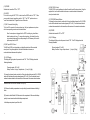
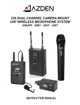
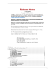
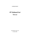
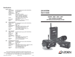
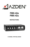
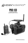
330 SYSTEM
User’s Guide
330UPR • 35BT • 35HT • 35XT
DUAL-CHANNEL ON-CAMERA
UHF WIRELESS MICROPHONE SYSTEM
1-12-17 Kamirenjaku Mitaka-shi Tokyo 181-8533 Japan
Tel :+81(0)422-55-5115 Fax :+81(0)422-55-0131
E-mail : [email protected] URL http://www.azden.co.jp
Printed in Japan 060-35513-01
CONFIGURATION OF THE PACKAGES
Adapted PLL synthesized control method provides constant audio receipt for dual audio receipt.
First make sure matched channel is used between receiver 330UPR and transmitters such as
35BT (bodypack transmitter), 35HT (handheld transmitter) and 35XT(plug-in transmitter). To get
best constant audio receiptant, should keep 10 channel difference between one microphone to
the other microphone. For example, setting CH1:001, other channel CH2: 011. 10 channel
difference avoid cross talk between these two microphone's operation.
Below shows the description of each part of goods.
① Anttena
Azden orginal anttena For keeping the orginal performance, dont move the anttena.
② Channel power switch
CH1 is for Channel 1 power on/off and CH2 is for Channel 2.
③ CH 1 and 2 display
Each chennel setting condition is displayed. For the details of Channel setting, go to the LCD
panel information clause.
④ Channel up / down button
By pressing it up and down, channel number is set up.
To push the botton, use phillips type screw driver or similar one.
To avoid the cross talk between CH1 and CH2, at least apart 10 channel or more between the
two channel. For example, CH1 is 001 and CH should be 0011 or upper number.
⑤ LCD panel switching button (DISP ?)
By pressing it, switch to either channel
Last selected channel is kept in memory and is displayed when the power is ON.
⑥ MODE switch
The button is anable for users to check currently using channel in“CH001”or“ actual using
frequency”.
⑦ Headphone jack
This jack allow users to monitor the input audio to the receiver.
Monirtering with stereo headphone, CH1 is left earphone side and CH2 is right earphone side.
⑧ Audio out jack CH1 and CH2(MIC OUT)
The 330UPR is supplied with both a mini(stereo) to mini(stereo) and a mini to dual XLR cable.
The contents of each package are described below.
Package: 330ULT
Description
330UPR Dual-Channel Receiver
Audio cable (XLRx2 – Stereo Mini plug)
Audio cable (Stereo Mini plug -Stereo Mini plug)
Velcro (Attaching receiver to portable mixer or camera)
Quantity
1
1
1
1
35BT Transmitter
Livelier microphone EX-553
2
2
Package: 330ULH
330UPR Dual-Channel Receiver
Audio cable (XLRx2 – Stereo Mini plug)
Audio cable (Stereo Mini plug -Stereo Mini plug)
Velcro (Attaching receiver to portable mixer)
1
1
1
1
35BT Transmitter
Livelier microphone EX-553
35HT Handheld Transmitter
1
1
1
Package: 330ULX
330UPR Dual-Channel Receiver
Audio cable (XLRx2 – Stereo Mini plug)
Audio cable (Stereo Mini plug -Stereo Mini plug)
Velcro (Attaching receiver to portable mixer)
1
1
1
1
35BT Transmitter
Livelier microphone EX-553
35XT Plug-in Transmitter
1
1
1
For mini jack mirophone inputs: Usethe supplied mini to mini cable. Plug one end fo the cable
into the receiver (CH1/CH2 audio out jack) and the other end of the calbe into the microphone
input of the video camera.
9
(10mW in Korea)
For 3-pin XLR microphone inputs: Use the supplied min to dual XLR cable. Plug the mini-plug
end of the cable into the receiver (user the screw-down sleeve to secure it to the receiver) and
plug the XLR ends of the cable into the microphone inputs of the video chamera
⑨ Battery compartment
Insert the fresh alkaline“AA”batteris into the compartment. Make sure the battery polarity is
connect as marked inside the battery compartment. Batteries are not packed as standard item.
Obtain “AA” alkarine batteries 2 pcs. Using Azden recommending re-chargeable batteris,
get AC/DC adapter for recharging from Azden and charge batteris for 8 hours to get full charge.
To make sure the batteris at full level, check three bar on the LCD is indicated.
⑩ AC/DC jack DC6V external voltage supply is adapted for re-charging Azden standard NiMH batteris after
installing them into the battery compartment. Azden original must need to get this feature.
Other rechargeable NiMH batteris are not accepted. Buy adapter/batteris from your nearest
dealers. Once the ac/dc is plugged, the external power supply is selected as the main power
even if the batteris are installed.
②
⑧
⑦
(10mW in Korea)
①
(10mW in Korea)
③
④
⑤
BATT
1 2
LEVEL
DOWN
UP
CHANNEL
DISP 1/ 2
MODE
⑥
⑩
⑨
8
⑨
1
Operation flow
Conenct the standard parcked cable “stereo mini plug - dual XLR”. Connect the stereo mini
plug side to the receiver and the dual XLR side to video camera. The dual XLR side, CH1 is white
color marking and CH2 is black color marking. Make sure matching channel set between the
receiver and video camera. Camcoder supports Phantom power supply through microphone jack.
Set the Phantom power supply feature to “off” position. Otherwise, it may damage the receiver.
The receiver and wireless microphone must user 1.5 m away or longer distance.
Othewise, it may cause the interference.
Using two receiver at the same field, each receiver must have 3m or longer
interval between thes two receivers.
Using the receiver with only one microphone, swtich off the other micrphone
power. Otherwise, no audio transimition may occurs.
330UPR shows channel information on the LCD panel. Currently set up“Channel number”or
“Frequency digit”can be switched via MODE switch (⑥)The details of channel figure refer
page 7. The default figure from our factory is CH1: 001 / 794MHz and CH2: 121 / 800.00.
1.LCD panel information
a : Current display channel on the LCD
Selected channel number condtion can be changed.
DISP ? can swtich either channel.
b: Current set channle number
Channel number wil be displayed and switched to
the actual frequency value by pressing MODE button.
Wheneever the power on, Channel number is displayed.
c: RF level indication with four bar
Four bar indication is strong and best audio receving status.
d: Battery status
Vertically “fout bar” is displayed when the power is at full condtion.
Dual channel model with “alkarive AA two batteries” can operate for
five hours.
When the last bottom bar start flushing, replace the batteries.
e: Auditon transmission “wireless frequency level” will be displayed through
mode menu.
a
c
BATT 1 2
LEVEL
BATT 1 2
LEVEL
→
2
b
These devices comply with Part 15 of the FCC Rules. Operation is subject to the following
two conditions: (1) These devices may not cause harmful interference, and (2) These devices
must accept any interference received, including interference that may cause undesired operation.
NOTE: The manufacturer is not responsible for any radio or TV interference caused by
unauthorized modifications to this equipment. Such modifications could void the user's authority
to operate the equipment.
on push
“MODE”
d
Important information
Licensing of this, or any Azden wireless equipment is the user's responsibility. The ability to
receive a license depends largely on the user's classification, application and frequency.
Contact the appropriate agency (FCC in the US) for further information.
e
These devices and their antenna(s) must not be co-located or operated in conjunction with any
other antenna or transmitter.
7
Operating the system
BODYPACK TRANSMITTER (35BT)
Because this is a frequency agile system, the receiver and transmitter must be on the same
channel number. To change the channel number, use the tip of the provided tool and press
the UP or DOWN button to the desired channel. Make sure both the receiver and
transmitter are on the same channel.
(11) Remove the battery compartment lid by sliding it down.
330UPR Receiver
After installing new batteries, mount the receiver to your video camera with the supplied
shoe mount or hook & loop fastener. Select one of the supplied cables and connect the
output cable to the receiver and to the microphone input on the video camera. Switch Ch.1
and/or Ch.2 of the 325PR to “ON” and the battery level indicator(s) should come on. If
they do not, check the batteries. When the 325UPR receives a signal from the transmitter
the reception level indicator will come on. If it does not, make sure both the receiver and
transmitters are on matching channels.
35BT Transmitter
Plug in the supplied lapel microphone and clip it to your subject. The microphone should be
placed 10-30cm( 4-12 inches) from your subject’s mouth. Clip the transmitter to a belt using
the supplied belt-clip or place it in a pocket. Switch the 35BT to “ON” and the battery level
indicator should come on. If it does not, check the battery. Have someone speak into the
microphone as you monitor the sound through the receiver’s phone output. If the sound is
distorted lower the MIC input level on the transmitter. If there is not enough volume raise the
MIC input level on the transmitter.
35XT Transmitter
Switch the transmitter to “ON” and the battery level indicator should come on. If it does not,
check the battery. Have someone speak into the microphone as you monitor the sound
through the camera’s monitor output. If the sound is distorted lower the level control on the
transmitter. If there is not enough gain raise the level control on the transmitter.
35HT Transmitter
Switch the transmitter to “ON” and the battery level indicator should come on. If it does not,
check the battery. Have someone speak into the microphone as you monitor the sound
through the camera’s monitor output. If the sound is distorted lower the level control on the
transmitter. If there is not enough gain raise the level control on the transmitter.
(12) Insert two fresh Alkarine "AA" batteries* into the compartment. Make sure the battery
polarity is correct as marked inside the battery compartment.
In addition to the battery, inside the battery compartment you will find:
(13) MIC Input LEVEL Control
This control enables you to adjust the input level of the microphone. Using the supplied
tool, turn the dial clockwise to increase, or counterclockwise to decrease the input level.
Depeds on microphone type, microphone input level differ.
(14) POWER
Switches the transmitter "ON" or "OFF"
(15) MIC Input Jack
Plug the supplied EX-503L microphone into the MIC input jack and tighten the collar until
snug (DO NOT OVERTIGHTEN). In addition to the EX-503L, other lapel and/or headset
microphones with 3.5mm mini plugs can also be used with the 35BT.
(16) LCD Display
This display shows the following information.
Channel Number: 001 to 240
Battery Condition: Using a 3 step indicator - 1 (Low) to 3 (High)
To change the channel number: Use the tip of the tool provided and press the UP or
DOWN button to the desired channel, number appears (001 to 240). Once the desired
channel number has been selected on the transmitter, set the receiver to the same
channel number.
(17) AUDIO
Prior to first turning the 35XT “ON” it is best to set the AUDIO switch to “OFF”. When
you are ready to begin transmitting, switch to “ON”. The “OFF” position acts as a
“mute” that maintains the RF signal but turns off the audio.
*While Alkaline batteries are preferred, you can use rechargeable Ni-Cd or Ni-MH batteries.
XLR PLUG-IN TRANSMITTER (35XT)
(18) Open the battery compartment lid by sliding it down and lifting it up.
Insert two "AA Alkrine batteries" into the compartment. Make sure the battery
polarity is correct as marked inside the battery compartment.
6
3
(19) POWER
Switches the transmitter “ON” or “OFF”.
(20) AUDIO
Prior to first turning the 35XT “ON” it is best to set the AUDIO switch to “OFF”. When
you are ready to begin transmitting, switch to “ON”. The “OFF” position acts as a
“mute” that maintains the RF signal but turns off the audio.
(21) MIC Connector/Locking Ring
This 3-pin XLR connector is the microphone input. Any low impedance microphone
with a corresponding connector can be attached here.
Once the microphone is plugged into the 35XT the locking ring should be rotated clockwise until snug. To remove the microphone, first rotate the locking
ring counterclockwise and then, while pressing the XLR release, pull the microphone away from the 35XT.
(26) MIC LEVEL Control
The MIC LEVEL control enables you to adjust the audio level of the microphone. Using the
supplied tool, turn the dial clockwise to increase, or counterclockwise to decrease the
microphone’s audio level.
(27) UP/DOWN Channel Buttons
To change the channel number, use the tip of the tool provided and press the UP or DOWN
button until the desired channel number appears (001 to 240). Once the desired channel
number has been selected on the transmitter, set the receiver to the same channel number.
(28) POWER
Switches the transmitter “ON” or “OFF”.
(29) LCD Display:
The display will light up when the power is turned “ON”. The LCD display shows the
following information.
(22) MIC Input LEVEL Control
The MIC input LEVEL control enables you to adjust the input level of the connected
microphone. Using the supplied tool, turn the dial clockwise to increase, or
counterclockwise to decrease the input level
21
Channel number: 001 to 240.
Battery Condition: Using a 3 step indicator - 1 (Low) to 3 (High)
(23) LCD Display:
The display will light up when the power is turned “ON”. The LCD display shows the
following information.
23
Channels number: 001 to 240
Battery Condition: Using a 3 step indicator – 1(Low) to 3 (High)
19
13
To change the channel number, use the tip of the tool provided and press the UP or DOWN
button until the desired channel number appears (001 to 240). Once the desired channel
number has been selected on the transmitter, set the receiver to the same channel number.
12
29
HANDHELD MICROPHONE/TRANSMITTER (35HT)
27
14
(24) Remove the battery compartment cover by rotating it counterclockwise and sliding it
down.
16
26
(25) Insert two fresh Alkaline “AA” batteries into the compartment. Make sure the battery
polarity is correct as marked inside the battery compartment.
In the battery compartment you will also find:
+
-
20
22
15
18
Belt Clip
24
25
-
24
17
+
11
28
4
5