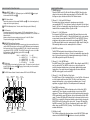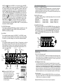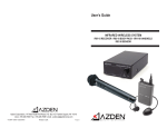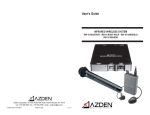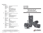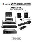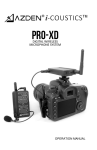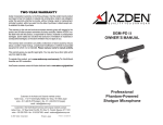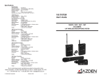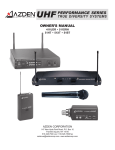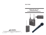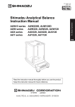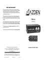
1
TWO-YEAR WARRANTY
Azden Corporation warrants, to the first purchaser, that the Azden brand product
purchased is free from defects in material and workmanship. Azden's sole obligation
under this warranty shall be to provide, without charge, repair or replacement
(at Azden's option), within two years from the date of purchase. A dated receipt acts
to establish the date of purchase.
This warranty is the sole and exclusive express warranty given with respect to the
product and all other express warranties are hereby excluded. Neither AZDEN, nor
the dealer who sells this product, is responsible for indirect, incidental or consequential
damages.
This warranty does not extend to any defect, malfunction or failure caused by misuse,
abuse, accident, faulty hookup, unauthorized modification or defective associated
equipment for which it is not intended. Please read your owner's manual carefully.
FMX-42a
INSTRUCTIONS
To register this product, go to www.azdencorp.com/warranty "for North/South
America and EU customers.
Asia/Oceania customers contact with Azden distributors listed on www.azden.co.jp/global.html
Customers in the Asian and Oceania markets contact:
Azden Corp., 1-12-17 Kamirenjaku Mitaka-shi, Tokyo, 181-8533 Japan
voice - 81-1-422-55-5115(Japan) • fax - 81-1-422-55-0131(Japan)
email - [email protected]
Customers in the North/South America and Europian markets contact:
Azden Corp., 147 New Hyde Park Rd, P.O. Box 10, Franklin Square, NY 11010
voice - 516.328.7500 • fax - 516.328.7506 • email - [email protected]
© 2007 Azden Corporation
Printed in Japan
P1040-01 060-35510-01
4-CHANNEL PORTABLE MIXER
BALLISTIC NYLON CASE
The FMX-42a is supplied with a ballistic nylon case. Place the mixer in the case and
adjust the neck strap to achieve the most comfortable position. For additional support
and comfort, if desired, a back harness (not supplied) can be secured to the metal rings
on the case.
XLR 3-pin Male x 2 (Output L & R)
Hirose 10-pin Female for Hirose Plug Part #RM15TD-10P
3.5mm (1/8") Stereo Mini-Jack
6.3mm (1/4") Stereo Jack
Standard: +4 dBu (electronically balanced, >10kΩ load)
Maximum: +20 dBu (electronically balanced, >10kΩ load)
Impedance: 600Ω
-36 dBu
Standard: -36 dBu (electronically balanced, >10kΩ load)
Maximum: -20 dBu (electronically balanced, >10kΩ load)
Impedance: 600Ω
Unbalanced Output Level Standard: -36 dBu (electronically balanced, >10kΩ load)
Maximum: -20 dBu (electronically balanced, >10kΩ load)
Impedance: 120Ω
Monitor Output
Maximum: +1 dBu (32Ω load at 9V)
16-100Ω load recommended
Meters
Standard Output Level: 0 VU (+4 dBu)
XLR 3-pin Female x 4 (CH1, 2, 3 & 4)
Standard: +4 dBu (electronically balanced)
Maximum: >+26 dBu
Impedance: 20kΩ
-30 dBu (MIC 1)
Standard: -38 dBu (electronically balanced)
Maximum: +4 dBu
Impedance: 2kΩ
-55 dBu (MIC 2)
Standard: -58 dBu (electronically balanced)
Maximum: -15 dBu
Impedance: 2kΩ
High Pass Filter (HPF) 100Hz - 6dB/oct
EXTERNAL POWER
The FMX-42a can be powered from an external power supply using a 12V AC adaptor
(not included*). When the FMX-42a is connected to an active 110VAC through an AC
adaptor and the POWER switch is turned ON, the batteries will be automatically
disconnected.
*An optional AC adaptor, part number BC-27H, is available. Call Azden for details.
INPUT
Balanced Input:
Level +4 dBu (LINE)
CAUTION
・Do not use other batteries than "AA" alkaline batteries. Do not mix fresh batteries
with used batteries.
・Remove the batteries if the mixer will not be used for a long period of time to prevent
battery fluid leak.
Unbalanced Output:
Monitor Output:
Balanced Output Level
+4 dBu
INSTALLING BATTERIES
Make sure that the POWER switch ⑯ is OFF. Remove the battery cover by pressing
the clip in and then lifting up the cover. Install 6 fresh"AA"alkaline batteries following
the polarity diagram inside the battery compartment. Do not force the batteries.
After all 6 batteries are properly installed, replace the battery cover and move the
POWER switch to the"ON"position. The POWER indicator LED ① in the front panel
will turn green.
OUTPUT
Balanced Outputs:
・Before turning the PHANTOM DC48V switch ON, make sure your condenser
microphone is designed to handle 48VDC or the microphone may be damaged.
Check the microphone's user manual or with the manufacturer of your microphone.
Input Level:
Impedance:
・When the PHANTOM DC48V power is not needed, make sure the PHANTOM switch
is in OFF position.
Hirose 10-pin Female for Hirose Plug Part #RM15TD-10P
3.5mm (1/8") Stereo Mini-Jack
-20 dBu - +19 dBu (unbalanced)
11kΩ
SAFETY INSTRUCTIONS
・When connecting/disconnecting cables, and/or changing the PHANTOM power
settings or INPUT LEVEL settings, make certain to turn the input LEVEL control
knobs to zero or to turn the POWER switch OFF.
Return Inputs:
It is very important to read and understand this manual completely before use. Keep
this manual for future reference.
FMX-42a SPECIFICATIONS
GENERAL
Frequency Response
Balanced or Unbalanced Output: 20 Hz - 30 kHz (+0/-1.5 dB)
Monitor Output:
30 Hz - 30 kHz (+0/-2 dB)
Signal-to-Noise Balanced Output: -120 dBu (A weighted, input equivalent level)
T.H.D. Balanced Output:
<0.005% @ 1 kHz (at LINE position +19 dBu output)
Phantom Power Voltage:
48V (±4V)
Sample Tone Frequency:
1 kHz
Battery Requireme:
6 Alkaline "AA"
Battery Runtime:
Approx.10 hours (Meter Illum & Phantom Power OFF)
External Power:
12V DC @ 200mA
Current Drain:
164mA (Meter Illum & Phantom OFF @ 9V)
192mA (Meter Illum OFF, Phantom ON w/1 MIC @ 9V)
125mA (Meter Illum & Phantom OFF @ 15V)
Dimensions:
220mmW x 160mmD x 56mmH (without protrusions)
9"W x 6 1/2" D x 2 1/4"H (without protrusions)
Weight:
1,350 grams/3 lbs (without batteries)
INTRODUCTION
Thank you for purchasing Azden's FMX-42a 4-channel portable mixer. The FMX-42a
was designed to work with most microphones that have a low-impedance XLR output
or line-level devices. Its output can be connected to virtually any video camera or
audio recorder, which has XLR or mini-connector mic/line inputs.
RIGHT-SIDE OUTPUT/CONTROL PANEL
22
⑳
⑳.Monitor
SELECT Switch
26 input signals
To SELECT either LINE OUT ⑰&⑱ output signals or CAMERA(RTN) ⑳
21
⑳
for the monitor PHONES output ⑳.
23
⑳
⑳.LEVEL
Volume Control
21 Zero is the lowest(quietest)
⑳
Controls the volume level of the monitor PHONES output ⑳.
setting and 10 is the highest (loudest).
24
⑳
⑳.METER
ILLUM(ination) Switch / Turn this switch ON to light up the VU Meters⑧.
25
⑳
⑳.DC
IN Connector
For external powering of the mixer, connect a 12V AC adaptor to this input. It is a
4-pin Hirose connector and an optional AC adaptor, part number BC-27, is available. Call
Azden for details.
Maximum rating of the power supply must not exceed 12 volts DC, 350mA.
*Required connecting plug: Hirose HR10A-7P-4P
26
⑳
⑳.CAMERA(RTN)
Input/Output Connector
This Hirose 10-pin connector allows you to connect your video camera and the mixer to
send the LINE OUT output signals and to receive the RETURN input signals simultaneously.
It will require the Hirose 10-pin plug (part #RM15TD-10P). Using this connector will not
cancel out the OUTPUT L & R ⑰&⑱. The LINE OUT output level can be set at +4 dBu
20
⑳
(LINE output) or -36 dBu (MIC output) by the LEVEL selector ⑳.
Connector Pin Configuration
Pin # 1 ----- LINE OUT L (+)
6 ----- NC
2 ----- LINE OUT L (-)
7 ----- RTN IN L (+)
3 ----- LINE OUT R (+)
8 ----- NC
4 ----- LINE OUT R (-)
9 ----- GND
5 ----- RTN IN R (+)
10 --- GND
27
⑳
⑳.RTN
Mini-Jack
A 3.5mm unbalanced stereo input jack for return signals. The volume level can be adjusted
28 Plugging a cable into this jack will cancel out the
⑳
by the RTN LEVEL volume control ⑳.
26 input.
CAMERA(RTN) ⑳
28
⑳
⑳.RTN
LEVEL Volume Control / Controls the volume LEVEL of the RETURN input.
DC IN
Connector
CAMERA(RTN)
Connector
25 RTN
⑳
26
⑰
Mini-Jack
27
⑳
24
⑳
OUTPUT
Connector L
MONITOR
PHONES
⑰
OUTPUT
Connector R
⑱
21
⑳
⑯
22
⑳
⑳
POWER
Switch
Monitor
SELECT
Switch
LEVEL
Selector
28
⑳
METER
RTN
ILLUMINATION LEVEL
Switch
Volume Control
23
⑳
⑲
STEREO MiniLEVEL
Volume Control Connector Output
FRONT CONTROL PANEL
①. POWER Indicator
When the POWER switch ⑯ is ON, the LED will turn GREEN. When the battery
voltage level becomes too low for proper operation, the LED will turn RED. When
this happens, replace the batteries with fresh "AA" alkaline batteries.
②. Channel 1, 2, 3 & 4 Input LEVEL Controls
Each knob controls the input volume of the microphone connected to the
corresponding INPUT ⑬. Zero is the lowest (quietest) setting while 10 is the highest
(loudest). For the best sound with the lowest possible noise, increase the input level
control until the corresponding VU Meter ⑧ peaks at 0 dB.
③. Channel 1, 2, 3 & 4 PAN Controls
Each channel of the FMX-42a has an adjustable PAN control (the outer-rim at the
base of the Input LEVEL control ②). When the PAN Control is in the center position,
an equal amount of sound will come from OUTPUT L ⑰ and OUTPUT R ⑱ for any
microphone or line-level input connected to the corresponding INPUT ⑬. Moving
the PAN control left will decrease the sound output in the Right channel. Moving the
PAN control right will decrease the sound output in the Left channel.
④. MASTER Level Control
The MASTER knob controls the overall volume of all connected sources
(microphones and/or line-level devices). For the best sound with the lowest possible
noise, try to keep this control set at its midpoint while maintaining the VU Meters ⑧
at the 0 dB range with the input LEVEL controls ②.
⑤. Channel 1, 2, 3 & 4 LIMITER Switch
Each INPUT channel ⑬ has a switchable LIMITER. After setting the input LEVEL ②,
turn this switch to ON. The LIMITER circuit acts as a safety and reduces the
possibility of overload distortion from very loud sounds without affecting normal
sound volume. If you prefer the overall sound quality of the mixer without the
LIMITER circuit engaged, leave the switch OFF.
⑥. Channel 1, 2, 3 & 4 HPF (High Pass Filter) Switch
Each INPUT channel ⑬ has a switchable High Pass (= Low Cut) Filter. When turned
on, it will cut input signals lower than 100Hz. This filter is useful for removing
unwanted low frequencies, such as wind and air-conditioning noise. For most
applications, engaging the High Pass Filter will improve overall sound quality.
⑦. Input PEAK Level Indicators
Each INPUT channel has 2 PEAK Level Indicators on the left side of the LEVEL
control knob ②.These Indicators are provided to help set precise input LEVEL
adjustments. The lower LED indicates the level of the input electronically prior to the
LEVEL control while the upper LED indicates the level electronically after the LEVEL
control. The lower LED lighting RED indicates that the item connected to the mixer's
INPUT ⑬ has a signal that is too high and should be reduced either by changing the
INPUT LEVEL switch ⑭ setting or at the device itself. The upper LED should only
light RED occasionally. If this LED stays lit continuously, lower the input LEVEL ②
and/or change your INPUT LEVEL ⑭ settings. These LEDs help reduce signal
overload and distortion.
⑧. VU Meters L and R
The VU Meters will show either the output volume level of LINE OUT ⑰&⑱ or input
26 , whichever is selected by the Monitor
volume level of CAMERA RETURN ⑳
22 . When the LINE OUT is selected, while keeping the MASTER
SELECT switch ⑳
control ④ at its midpoint, increase or decrease each channel's LEVEL control ② until
the L and/or R VU Meter peaks at 0 dB. If the LEVEL is set too low, sound may be
accompanied by background hiss. If the LEVEL is set too high, the sound may be
distorted. Monitor the sound with headphones and adjust the LEVEL for the best
sound. An OUTPUT PEAK Indicator LED ⑨ will light RED if your overall levels are
set too high. When the CAMERA RTN is selected, adjust the volume level by the
28 .The VU Meters are set to reflect the selection by the Monitor
RTN LEVEL switch ⑳
22 by the factory. However, if you would prefer, you may change
SELECT Switch ⑳
the setting to always show the output volume level of LINE OUT regardless of the
22 setting. Remove the bottom plate by removing the 2
Monitor SELECT switch ⑳
screws on each side and 3 screws on the bottom. Locate the SW2 switch on the
circuit board and change the setting from "MONI" to "LINE". The center position is to
disconnect the VU Meters altogether.
⑨. OUTPUT PEAK Indicators
These indicators monitor the LINE OUT outputs. When the overall levels are set too
high, the LEDs will light RED. Adjust the INPUT LEVEL controls ② and/or the
MASTER level control ④ accordingly.
⑩.SLATE MIC
Press and hold this button to engage the SLATE MIC. The SLATE MIC is used to
pick up audio at the mixer's location and is not intended for serious audio recording.
It is however, very useful for notating scenes or other on-location documentation.
⑪.1 kHz TONE
Press and hold this button to generate the 1 kHz tone. This output tone is used to set
the recording levels of your video camera or audio recorder to their optimum level.
While generating the 1 kHz tone, set the recording levels of your video camera or
audio recorder to the specified level as recommended by the manufacturers. The
signal is generated at +4 dBu.
VU Meters
Battery Case
Input LEVEL
Controls
② PAN
Controls
③
⑫ MASTER
Level Control
④
⑧
OUTPUT
PEAK Indicators
⑨
LEFT-SIDE INPUT/CONTROL PANEL
⑬.Channel 1, 2, 3 & 4 INPUT Connectors
Connect the 3-pin XLR output of a microphone, wireless receiver or line level audio
component to INPUT CH 1 and/or CH 2 and/or CH 3 and/or CH4. Push the XLR
connector into the INPUT jack until it locks. To remove the XLR connector, press the
PUSH tab and pull the connector out.
⑭.INPUT LEVEL Selector
The following 3 different settings are available depending on the source connected to
the INPUT connectors ⑬:
+4 dBu (LINE) →
Standard: +4 dBu →
Maximum: >26 dBu (20 kΩ)
-30 dBu (MIC 1) →
Standard: -38 dBu →
Maximum: +4 dBu (2 kΩ)
-55 dBu (MIC 2) →
Standard: -58 dBu →
Maximum: -15 dBu (2 kΩ)
⑮.PHANTOM DC48V Switch
Each channel of the FMX-42a has its own PHANTOM DC48V power setting. When
using a dynamic microphone, be sure to turn the corresponding PHANTOM DC48V
switch to the OFF position. When using a condenser microphone that requires 48V
DC external power, turn the corresponding PHANTOM DC48V switch to the ON
position. The PHANTOM DC48V only operates in the -30 dBu or -55 dBu INPUT
LEVEL setting ⑭.
INPUT
Connectors
⑬
INPUT LEVEL
Selector
⑭
⑮
PHANTOM
Switch
RIGHT-SIDE OUTPUT/CONTROL PANEL
⑯POWER Switch
⑰.& ⑱.OUTPUT Connector L and R
Connect a cable from OUTPUT L and/or R to the microphone or line input of your video
camera or audio recorder. These outputs accept a standard 3-pin female XLR connector.
Push the XLR connector into the OUTPUT jack until it locks. To remove, press the release
tab on the XLR connector and pull the connector out.
PEAK 2
Indicators
⑦
PEAK 1
Indicators
①
⑤
POWER
Indicator
LIMITER Switch
⑩
⑧
SLATE MIC
⑥
⑪
HPF Switch
1kHz TONE
●VU Meters LINE OUT SELECT switch
LINE OUT
↑
OFF
↑
Remove the bottom plate by removing
the 2 screws on each side and 3 screws
on the bottom. Locate the SW2 switch
on the circuit board and change the
setting from "MONI" to "LINE".
The center position is to disconnect the
VU Meters altogether.
MONI SELECT
SW 2
⑲.STEREO Mini-Connector Output
The STEREO mini-connector (3.5mm) output is designed for video cameras or audio
recorders with mini-connector microphone-level inputs. This output is stereo(dual-channel)
and unbalanced. The standard output level is fixed at -36 dBu. It is recommended to use
a stereo-to-stereo mini cable (not supplied) from the STEREO mini-connector output to the
input of your video camera or audio recorder. Because the FMX-42a is equipped with lowimpedance XLR inputs and a mini-connector output, users of mini DV cameras with miniconnector microphone inputs can now use high-quality microphones with XLR outputs.
⑳.LEVEL Selector
Select the OUTPUT ⑰&⑱ and/or CAMERA RTN ⑳ LEVEL that is best suited for your
video camera or audio recorder. The +4 dBu setting is for line-level audio inputs and the
-36 dBu setting is for a microphone-level audio input.
⑳.Monitor PHONES Output Jack / A 6.3mm (1/4") jack for headphones.