1
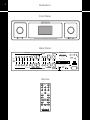
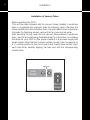
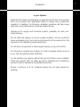
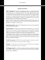
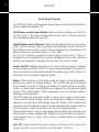
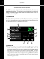
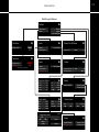
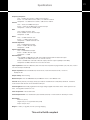
User Guide
SP20
Stereo Preamplifier
H I G H
D E F I N I T I O N®
2
Contents
Preface 3
Illustrations 4
Warnings 5
Installation
Installation of Vacuum Tubes 6
In Your System 7
Connections 8
Operation
Power-Up Procedure 9
Front Panel Controls 10
Remote Control Only Controls 11
Interactive Touch Screen Operation 12 - 17
Troubleshooting 18
Maintenance
Servicing 19
Cleaning 19
Disposal and Recycling Guidelines 19
Limited Warranty 20
Specifications 21
Preface
Thank you for selecting the SP20 as part of your music
listening system. The engineers and designers at Audio
Research have spent countless hours of listening and
testing to create a preamplifier of the highest caliber for
music reproduction. The SP20 has been designed to
provide you many years of playback.
Please take a few minutes to read through this guide
to help you better understand and optimize your new
preamplifier. If you have any questions regarding the
operational functions, contact your dealer or distributor
for assistance.
Sit back and enjoy your new preamplifier and the
enhancements it will bring to your system. The SP20 will
bring new life to your entire music collection.
Happy listening!
3
4
Illustrations
Front Panel
SOURCE
POWER
VOLUME
SP20 VACUUM TUBE STEREO PREAMPLIFIER HIGH DEFINITION
MUTE
®
PHONES
SPKR OFF
Back Panel
RIGHT INPUTS
MODEL SP20
RIGHT OUTPUTS
RS-232
IR INPUT
STEREO PREAMPLIFIER
PLYMOUTH, MINNESOTA
MADE IN U.S.A.
+12V REMOTE
TRIGGER
(30mA max)
CAUTION
FOR CONTINUED PROTECTION AGAINST
FIRE HAZARD REPLACE FUSE ONLY
WITH SAME TYPE AND RATING
GROUND
PHONO
SE1
SE2
SE3
SE4
MONITOR
BAL1
BAL2
RECORD
MAIN 1
MAIN 2
MAIN 3
CAUTION
RISK OF ELECTRIC SHOCK
DO NOT OPEN
VOLTS
!
SERIAL
WARNING
TO PREVENT FIRE AND SHOCK HAZARD, DO NOT
EXPOSE THIS DEVICE TO RAIN OR MOISTURE.
UNIT MUST BE OPERATED IN A HORIZONTAL POSITION.
-DO NOT OPERATE WITH COVERS REMOVEDUNIT CONTAINS VOLTAGES WHICH MAY BE HAZARDOUS.
LEFT INPUTS
LEFT OUTPUTS
Remote
HOURS
SP20
POWER
SE1
SE2
SE3
SE4
BAL1
BAL2
INVERT
PHONO
MONO
BAL L
VOL DN
BAL R
MUTE
LOAD
DSP DN
H I G H
VOL UP
SPKR OFF
MON
DSP UP
D E F I N I T I O N®
1.5 A FUSE
SLO-BLO
T630MA
(230V)
30W MAX
50/60HZ
~
Warnings
To prevent fire, or shock hazard, do not expose your SP20 to rain or
moisture. Do not place containers with liquid on top of unit.
This unit contains voltages which can cause serious injury or death. Do
not operate with cover removed. Refer servicing to your authorized Audio
Research dealer or other qualified personnel.
The detachable power cord on your SP20 is equipped with a heavy gauge,
3-conductor cable and a standard three-prong grounding plug. For
absolute protection, do not defeat the ground power plug. This provides
power line grounding of the SP20 chassis to provide absolute protection
from electrical shock.
For continued protection against fire hazard, replace the fuse only with the
same type and rating as specified at the fuse holder.
The appliance coupler at the rear of this unit must be accessible for
emergency power disconnect.
A note about packaging...
Save all packaging in a dry place away from fire hazard. Your SP20 preamplifier
is a precision electronic instrument and should be properly cartoned any
time shipment is made. You may not have occasion to return your unit to
the factory for service, but if that should prove necessary, or other occasion
requiring shipment occurs, the original packaging will protect your SP20
from unnecessary damage or delay.
5
6
Installation
Installation of Vacuum Tubes
Before operating the SP20...
This unit has been shipped with the vacuum tubes installed in protective
foam in a separate box packed inside the shipping carton. Remove the
tubes carefully from the protective foam. Using a phillips-head screwdriver
to loosen the fastening screws, remove the top cover and set aside.
After removing the top cover and the vacuum tubes packed in protective
foam, see the accompanying illustrated sheet for instructions on installing
the tubes for your SP20 in their proper locations in the power supply and
audio chassis. Note that the numbers written on each tube correspond to
a ‘V’ number printed on the circuit board next to each tube socket. Insert
each tube firmly, carefully aligning the tube pins with the corresponding
socket holes.
CHANNEL
R
Line
Stage
V2
L
V1
V3
V4
Phono
Stage
Installation
In your System
While the SP20 does not dissipate an unusual amount of heat, it is important
that it be provided with reasonable airflow to assure long, trouble-free
operation. In addition, the following installation guidelines will help insure
maximum sonic performance as well as reliable service:
Operate unit in upright and horizontal position, preferably on solid, nonmetal shelving.
Do not stack the preamp on top of a power amplifier: not only could this
cause overheating, but hum may be introduced into the preamp from the
proximity of the amplifier’s power transformer.
Do not stack components or other objects directly on top of the SP20.
Do not place or operate your preamp on a soft or irregular surface such as
a rug. This will prevent proper ventilation.
Do not operate your preamp without the top and bottom covers installed.
These are required both for safety as well as shielding from interference
(except in service operations by qualified personnel).
Ensure a minimum of 8-10” clearance above the unit when placed on
shelving.
7
8
Connections
Analog Connections
Input Connectors: The SP20 provides five pairs of single-ended input
connectors: SE1 - 4, PHONO and MONITOR. Please note that input SE4
can be selected as a unity gain input; in this case, SE4 should only be
connected to a component with a volume control (such as a home theater
processor). For further information about the SE4 unity gain (PROC mode),
see the section ‘PROC Mode’ on page 16. In addition, there are two pairs
of balanced input connectors: BAL1 and BAL2.
Never connect a source with a fixed level output (DVD player, tuner, CD
player, etc.) to the unity gain input. This could cause serious damage to the
amplifiers or speakers in your system.
Output Connectors: Two pairs of balanced and one pair of single-ended
main outputs are provided.
Record Output: The tape outputs should be connected to your recorder’s
‘Record’ or ‘Line’ inputs. These outputs provide a fixed-level two-channel
signal (L, R) to your recorder from whichever input is selected. The fixed
output level will be the same as the output of the selected source.
It is possible to dub or copy from one recorder to another by connecting the
output of the source recorder to an unused set of stereo inputs (e.g. SE2 or
BAL1). The signal will then be routed to the Record Out connectors when
that input source is selected.
RS-232 Connection: The RS-232 connection allows for remote control via
systems such as Creston or other automation systems.
IR Input: The IR input can be used to link the SP20 to an IR repeater
system with a standard mono 1/8” connector.
12V Trigger Jack: The +12V DC output connector provides the ability to
remotely turn on and off other linked components such as power amplifiers
having similar capabilities.
Operation
Power-Up Procedure
• Secure all rear-panel connections between SP20, power amplifier(s) and
input sources.
• Plug three-prong power cord from rear of chassis into grounded A.C. wall
outlet. The Power switch defaults to ’off’ when the unit is plugged into a
power receptacle.
• Press power switch (either on the remote or front panel). The screen will
begin the warm-up sequence, first displaying the Audio Research logo,
followed by SP20 and a series of dots (fig. 1 + 2). The home screen will
then appear, and the unit will be muted. Depress the front panel MUTE
button (right button) or the Mute button on the remote to initiate normal
operation.
• Select input source and adjust the volume as necessary.
fig. 1
fig. 2
Shut-Down
• Activate ‘Mute’ function.
• Set Volume level to 0.
• Turn off power amplifier(s).
• Press Power switch to ‘off’.
• Turn off input sources.
9
10
Operation
Front Panel Controls
The SP20 has two microprocessor-driven rotary controls and three buttons
(Power, Mute and Speaker Off).
Left Rotary control (Input Select): Select input by rotating the control to
the left or right. The screen displays the current input by factory-set and
user-definable name at the top right.
Right Rotary control (Volume): Adjust volume (output level) up or down for
both L and R channels. Volume control is also selectable via Vol UP and Vol
DN buttons on the remote control. Volume adjustment is indicated in the
display window by numeric digits on 0–103 scale.
Do not turn volume up beyond normal listening levels when ‘mute’ is
engaged to avoid unexpected or possibly damaging sound levels. Reduce
volume level whenever changing input sources, even when muted.
Power On/Off: Supplies power from A.C. wall outlet to preamp; indicated
by active display window. The SP20 requires approximately 30 seconds to
warm up; this time is required to stabilize the power supply. See ‘Power-Up
Procedure’ on the adjacent page for details.
Mute: When activated, electrically mutes all output of the preamplifier;
indicated by ‘Mute’ in display window. This control should be activated
before switching inputs, changing connections or shutting down your audio
system to help protect your amplifier and speakers from unexpected signal
pulses. When deactivated, ‘Mute’ disappears from the display window
allowing normal operation.
The SP20 also has automatic muting to help protect system components
in the event of low line voltage. When sensing low line voltage, the preamp
displays ‘Low Line’ and automatically goes into ‘Mute’. This condition will
persist until the line voltage returns to a safe operating level; please note the
unit will remain in ‘Mute’ even after ‘Low Line’ no longer appears.
Note that automatic muting is only designed to protect against power line
interruptions or severe voltage drop. It will not mute in the event of subsonic
transmissions from a faulty input source, amplifier failure or speaker
malfunction.
Spkr Off: Toggles between the main outputs on the back of the unit and the
headphone jack mounted adjacent to the Speaker Off button.
Operation
Remote Control only Functions
Input Buttons: Allows direct selection of each of the 7 inputs of the SP20.
Please note that input SE4 is user-selectable to function as a unity gain
(processor) input. When engaged and SE4 is selected, ‘Unity Gain’ will
appear in the display and the volume control will be defeated. Before
selecting the unity gain input, be sure to turn down the volume on your
connected processor/source.
BAL/SE: Select as appropriate for each input. For source components
having balanced (XLR) connections to the SP20, select BAL. For singleended (RCA) sources, select SE. Once selected for an input source, the
setting is memorized.
Invert: Inverts absolute phase of the output signal.
Mono: Sums L and R input for mono output from any source selected.
Display Down/Display Up (DSP DN/DSP UP): Decreases/increases
display timeout; for more information about the timeout screen see ‘Display’
on page 17.
Balance (BAL L/BAL R): Adjusts balance left or right. Adjustment
appears in display window as movable marker on bar graph. Useful for
compensating for uneven speaker placement or imbalanced output from a
source component.
Hours: When pressed, displays number of operating hours vacuum tubes
have been in service. NOTE: After replacing tubes, this function should
be reset to ‘0’. See further instructions under ‘Hours Meter’ in the section
‘Interactive Touch Screen Operation’ for details.
Load: Selects cartridge load for a connected turntable. Options include
100, 200, 500, 1000 and 47k Ohms.
Monitor (MON): Toggles between the selected input (displayed on the
front panel) and the monitor input from a recording source.
11
12
Operation
Interactive Touch Screen Operation
The SP20 has been designed with a 4.3” interactive touch screen for
reliable and easy usage. The interface is programmed to be as intuitive and
straight-forward as possible. Please review the following section to get the
most from your preamplifier.
The Home Screen
The Home Screen provides the current status and operating functions of
the SP20. Once you have set up the preamplifier, the Home Screen will be
the most used interface for operating your system.
2
3
1
7
4
8
5
6
8
1 Input Name
9
10
The input currently in use is displayed in the top left corner. To change
inputs, use the rotary controller on the left side of the SP20. There are
two names displayed; the top name in smaller print is the given name of
the input which corresponds to the name on the back panel. This name
is fixed and not changeable. The second name in larger text is a userassignable name which can be configured up to eight characters. Please
see ‘Change Input Label’ in the settings menu for further instructions on
customizing input names.
Operation
2 Monitor
Indicates when the Monitor input is selected. To select the monitor
input, touch anywhere in the input name area of the screen, or push the
monitor button on the remote.
3 Volume
The large green number in the top right corner shows the master volume.
The volume range is from 0-103. Set volume levels can be programmed
so that when the SP20 is initially powered on, the volume is always
at the same number. Likewise, individual set volumes for the speaker
(main) outputs and headphone output can be set to prevent unexpected
volumes while switching between outputs. See ‘Volume Presets’ in the
settings menu for further instructions on setting output levels.
4 Stereo/Mono
Select between stereo and mono (summed L and R channel) playback.
This feature is useful when listening to recordings which were originally
recorded in mono sound. To switch between stereo and mono, touch
the box on the screen.
5 Phase Normal/Invert
Select between normal (non-inverted) and inverted phase. This feature
can be used in the event a recording is inverted phase. To switch
between normal and inverted, touch the box on the screen.
6 Load
Select the appropriate impedance for a turntable cartridge (phono input
only). Load options include 50, 100, 500, 1000, and 47k Ohms. To
toggle through the impedance options, touch the box on the screen.
7 Mute
Indicates when Mute is engaged. Pressing the right button under the left
rotary knob will toggle between mute and operate.
13
14
Operation
In the following explanations, the icon(s) associated with the function
are shown in the left column.
8 Balance
L
0
The Balance control adjusts the output from center position to the left
or right channels. To adjust balance, touch the balance icon and the
balance slider will appear in the space above it. When the balance
slider is present, touching either the ‘L’ or ‘R’ will move balance from
the center point towards either the left or right channel, and the center
number will change (-22 to -1 is balanced left while 1 to 22 is balanced
right). Simultaneously, the balance icon will turn green, indicating the
R
balance is towards the left or right. Touching the number in the middle
of the balance slider will set it to 0 and re-center the balance.
9 Output Selection
Indicates the active output of the preamplifier. The preamplifier can be
selected to send signal to the main output or the headphone output.
Please note that both outputs can not function simultaneously. To
select between speaker (main) and headphone output, press the button
labeled ‘Spkr Off’, located on the right side of the front panel adjacent to
the headphone connector, or press the ‘Spkr Off’ button on the remote
control.
Note: When selecting between speaker (main) and headphone outputs,
the SP20 will automatically change the volume to a predetermined
number as set in the ‘Output Settings’ menu.
10 Settings
The settings menu allows you to make function and visual adjustments
to the SP20. Touching the settings icon will take you to the main settings
menu where you can choose from a number of options to customize the
performance of the preamplifier. Any time you are in the settings menu
or one of its submenus, you can touch the ‘Home’ icon in the top right
corner to return to the home page. Additionally, the settings icon will
turn red and function as a signal in the event that the tube hours counter
has exceeded 4000 hours (see the section ‘Tube Hours’ on page 16
for further explanation of this function). For a full explanation of all the
features of the settings menu, please see the following section.
Operation
Settings Menu
or
15
16
Operation
Settings Menu
The features of the settings menu allow you to control certain parameters
as well as customize aspects of the SP20. The following section will explain
each component of the settings menu and explain their function.
Tube Hours: The Tube Hours displays the total number of hours the SP20
has been running. This is useful to gauge tube life and prepare for eventual
replacement. When the counter reaches 4,000 hours, the ‘Settings’ icon
on the home screen will turn red, along with the numbers in the tube hours
counter. A message will appear at the bottom of the tube hours page
recommending replacement of the vacuum tubes. Touching ‘Reset’ and
then ‘Confirm’ will set the counter back to 0 hours, as well as return the
‘Settings’ icon and counter numbers to their normal color.
Inputs: The Inputs submenu allows you to assign a name to each input, as
well as adjust the gain for each input individually.
Input Gains: You may experience some devices playing consistently
louder than others (for example, a CD player may always play louder than a
turntable). In this event, the Input Gains feature can be engaged to balance
the overall volume between the differing inputs, alleviating the need to
adjust the master volume when changing between inputs. The Input Gains
screen is designed so you can make adjustments easily to each input in
real time. For best results, have all devices connected to the SP20 playing
simultaneously, and from the Input Gains page, change inputs by rotating
the input rotary control. If one input is louder or softer than another, use the
up and down arrows to adjust accordingly.
Input Label/Change Input Label: On the home screen, the larger input
name can be customized with up to eight characters. To do so, select
Input Label from the Inputs submenu, and then select the input you wish
to customize. Use the left and right arrows to change characters. Once
the appropriate character is displayed, touch ‘Enter’ to move to the next
position. If you have made an error, use ‘Delete’ to move the cursor back.
Once you have finished the customized label, touch ‘Store’. If you wish
to return the label to the factory setting, touch ‘Default’. Use the return
arrow in the top right corner to return to the Input Label screen to change
another input name.
PROC Mode: Input SE4 can be set to unity gain in the event a component
with a volume control will be connected to the SP20 such as a home
Operation
theater processor. To engage the PROC mode, simply touch the label. A
red ‘Confirm’ button will appear beneath the PROC mode button; touch it
to turn on (or off) the unity gain setting. When engaged the PROC Mode
button will display ‘On’.
System: The System submenu allows you to set volume presets for each
of the two outputs of the SP20, check the software version, and set the unit
back to factory defaults.
Reset Defaults: To reset the SP20 to the original factory settings, touch
the ‘Factory Defaults’ button, followed by confirm. This will erase any
customized data you have stored.
Volume Presets: The speaker (main) and headphone output volumes can
be customized so that when switching between the outputs, inadvertent
equipment or hearing damage may be avoided. From the System submenu,
select Volume Presets. Use the up and down arrow buttons to change
the preset volume for each output. Note that each time you switch from
one output to the other, the volume preset takes effect and will adjust the
volume according to the customized settings.
SP20 About: Touching the ‘About’ button displays a screen with the current
software version of the SP20. This information can be useful in the event
the SP20 needs troubleshooting.
Display: The Display submenu allows you to adjust the screen timeout and
the brightness of the green bar on the timeout screen. To adjust brightness,
move your finger along the slider between the two icons. The green line
will change in brightness relative to the position of the arrows on the slider.
To adjust the screen timeout, moving the slider will change the timeout
from ‘Always On’ to up to 12 seconds. When engaged, the timeout feature
will dim the screen when no input (from touching the screen or using the
remote) is sensed for the assigned time period.
System Auto Shutdown: As an energy-saving measure, the SP20 offers
an auto-shutdown feature. When engaged, the SP20 will automatically shut
off after the specified amount of time from turn-on. The default setting is
‘always on’; moving the slider towards the right, ‘always on’ will no longer
appear, and on the right side of the slider, the number will correspond to the
auto shut off time (in hours).
17
18
Operation
Troubleshooting
It is possible for a static discharge to temporarily disable the microprocessor
that allows the controls to function. If this should occur, depress the ‘Mute’
button, then turn off the preamp and unplug the preamp from the A.C.
receptacle for 60 seconds. Reconnect the A.C. plug and turn the preamp
back on, along with other components. The controls should resume normal
operation. If the problem persists, contact your dealer or Audio Research
Customer Service at 763-577-9700.
Maintenance
Servicing
CAUTION: Your SP20 contains sufficient levels of voltage and current to be
lethal. Do not tamper with a component or part inside the unit. Refer any
needed service to your authorized Audio Research dealer or other qualified
technician.
The vacuum tubes inside your SP20 are quality tubes and with normal
use should not need to be changed for approximately 4,000 hours of use.
Replacement tubes should be of equivalent quality and are available from
Audio Research. Note that tube numbers (V1, V2 etc.) match printed
numbers next to tube sockets on circuit board.
Should service be necessary, please contact your Audio Research dealer,
or Audio Research Customer Service at 763-577-9700.
Cleaning
To maintain the new appearance of this unit, occasionally wipe the front
panel and top cover with a soft, damp (not wet) cloth to remove dust.
A mild, non-alkaline soap solution may be used to remove fingerprints or
similar smudges. Cleaners containing abrasives should not be used as they
will damage the anodized finish of the front panel. A small, soft paintbrush
is effective in removing dust from bevels, the recessed nameplate and other
features of the front panel.
Disposal and Recycling Guidelines
To dispose of this electronic product, do not place in landfill. In accordance
with the European Union Waste Electrical and Electronic Equipment (WEEE)
directive effective August 2005, this product may contain regulated materials
which upon disposal require special reuse and recycling processing.
Please contact your dealer or importing distributor for instructions on
proper disposal of this product in your country. Or, contact Audio Research
Corporation (763-577-9700) for the name of your importing distributor and
how to contact them.
Packing and shipping materials may be disposed of in a normal manner.
19
20
Limited Warranty
Audio Research Corporation products are covered by a 3-Year Limited
Warranty, or a 90-Day Limited Warranty (vacuum tubes). This Limited
Warranty initiates from the date of purchase, and is limited to the original
purchaser, or in the case of demonstration equipment, limited to the balance
of warranty remaining after original shipment to the retailer or importer.
In the United States, the specific terms, conditions and remedies for fulfillment
of this Limited Warranty are listed on the warranty card accompanying the
product in its shipping carton, or may be viewed at online at http://www.
audioresearch.com/warranty. Outside the United States, the authorized
importing retailer or distributor has accepted the responsibility for warranty
of Audio Research products sold by them. The specific terms and remedies
for fulfillment of the Limited Warranty may vary from country to country.
Warranty service should normally be obtained from the importing retailer or
distributor from whom the product was purchased.
In the unlikely event that technical service beyond the ability of the importer
is required, Audio Research will fulfill the terms and conditions of the Limited
Warranty. Such product must be returned at the purchaser’s expense to
the Audio Research factory, along with a photocopy of the dated purchase
receipt for the product, a written description of the problem(s) encountered,
and any information necessary for return shipment. The cost of return
shipment is the responsibility of the purchaser.
21
Specifications
Frequency Response:
Line: ± 0.3dB 2 Hz to 80 kHz; -3dB 0.8Hz to 220 kHz
Phono: ± 0.1dB of RIAA 10Hz to 20kHz; ± 0.4dB 5Hz to 80kHz
Headphone: ± 0.05dB 20Hz to 20kHz; -3dB 0.8Hz to 220kHz
THD+N:
Line: < .003% at 2V RMS, Bal output
Phono: < .005% at 3V RMS output, to Record output
Headphone: < .009% at 1V RMS output
Gain:
Line: 13.8dB, Processor: 0dB
Phono: 58dB @ 1KHz to Record output
Headphone: 11.3dB
Noise:
Line: <-101dBV volume at max.
Phono: < -77dBV to Record output
Headphone: < -88dBV volume at max.
Channel Separation:
Line: > 105dB Balanced output
Phono: > 76dB to Record output
Headphone: > 62dB
Signal to Noise Ratio:
Line: > 125dB Balanced output
Phono: > 94dB to Record output
Headphone: > 110dB
Rated Outputs: Line: 2V RMS (1V RMS SE) into 200k ohms balanced load (maximum balanced output capability is 18V RMS at less than .5% THD+N at 1kHz.)
Phono: 0.5V RMS into 100k load at Record output (maximum output capability is 25V RMS)
Headphone: 6V RMS maximum into 30 to 300 ohm load.
Input Impedance: 120k ohms Balanced, 60k ohms SE; Phono impedance programmable (100, 200, 500, 1000 or
47k ohms w/200pf unbalanced).
Output Impedance: 500 ohms Balanced, 250 ohms SE; 1000 ohms Record Out SE; <.05 ohms Headphone SE.
Output Polarity: Non-inverting.
Maximum Input: Line: 19V RMS Balanced, 9V RMS SE. Phono: 70mV RMS at 1kHz.
Controls: Rotary Volume (104 steps), Rotary Input selector. Push Buttons: Power, Mute, SPKR Off. Interactive
Touch Screen. Rear RS-232 control and Remote IR input.
Power Supplies: Electronically regulated low and high voltage supplies. Automatic 30 sec. warm-up/brown-out
mute. Line regulation better than .01%.
Tube Complement: 4 6H30 dual triode.
Power Requirements: 100-125VAC 60Hz (200-250VAC 50/60Hz) 77 watts maximum. Standby 2.7 watts.
Dimensions: Width 19” (48 cm)
Height 5.25”(13.4 cm) (standard rack panel)
Depth 16.5”(42 cm) D.
Weight: 17.8 lbs. (7.4 kg) Net; 27.8 lbs. (10.5 kg) Shipping.
This unit is RoHS compliant
H I G H
D E F I N I T I O N®
www.audioresearch.com
Specifications subject to change without notice.
©2013 Audio Research Corporation.