1
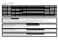
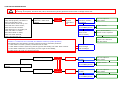
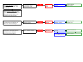
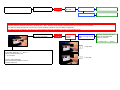
Advanced Heating Technologies b.v.
Wall hung, fan flue, room sealed, high efficiency gas boiler
TROUBLE SHOOTING MANUAL EN
Models:
15B
15C
30B
30C
30K
40C
TWIN80C
(partly)
COOPRA Advanced Heating Technologies b.v.
Vierlinghstraat 14
NL 3316 EL, Dordrecht
Tel: +31 (0) 78 – 653 08 30
Fax: +31 (0) 78 – 653 08 33
2006
E000129004
Trouble shooting manual EN E000129004
Table of contents
1.
Overall information
1.1.
1.2.
1.3.
1.4.
1.5.
1.6.
1.7.
1.8.
Overall view……………………………………..………………. 3
Hydraulic diagram
Nomenclature……………………………………….………….. 4
Cover removal
Emptying the main circuit
Emptying the d.h.w. circuit
Control panel
Condensate trap route…………………………………….. 5
3.12.
1
1
1.
2
2
2.
3
4
4
4.
5
6
7
8
9
9
A
A
A/C.
A/d.
A/b.
b/r
2.
Checks, servicing and replacement of
components
2.1.
2.2.
2.3.
2.4.
2.5.
2.6.
2.7.
2.8.
2.9.
2.10.
2.11.
2.12.
2.13.
Fan, gas valve and venturi assembly……….…….. 6
Burner……………………………………………………..………… 7
Pump
Main circuit pressure sensor……………………..…….. 8
Flow water temperature sensor
Return water temperature sensor……………….…. 9
D.h.w. heat exchanger sensor
Three-way diverter valve……………………………..….. 10
C.h. pressure relief valve…………………………….…… 12
Electronic control p.c.b.
Display
Glow plug and ionisation rod…………………………... 13
D.h.w. heat exchanger………………………………….... 13
3.
FAULT FINDING
3.1.
3.2.
3.3.
3.4.
3.5.
3.6.
3.7.
3.8.
3.9.
3.10.
3.11.
Burner states
Pump test (each boiler start)
Temperature test (each boiler start)
Pump monitoring (during operation)
System water pressure monitoring (operation)
Stand-by
Pre-rinse
Ignition
In operation
Post-rinse
Pump afterrun
Burner is on
Burner is off
Display
Blocking
Lock-out
STATUS INDICATIONS
All known indications listed:
……………………………….….. flashing
………………………………..…. continuous
…..(1+dot)
……...…. continuous
…………………...………....… flashing
………………………………..…. continuous
…..(2+dot)
……..…. continuous
……………………………………. flashing
……………….…...........…… flashing
………………..……………..…. continuous
…..(4+dot)
…….….. continuous
……………..…….…………….. flashing
……………..….…………..…… flashing
……………....…..........….. flashing
…………….….…………..……. flashing
…………….….…………….….. flashing
……….………..…………..…… continuous
…..(large A)
……….… flashing
…..(large A)
……..…. continuous
…..(large A/C+dot)
continuous
…..(large A/d+dot)
continuous
…..(large A/b+dot)
continuous
…..(small b/r)…………..… continuous
Chimney sweeper function
C
…..(large C)
…….…… flashing
C
d
b
J
C
C.
d.
b.
c
E
E
F
H
H
h
nc
O
O
o
o.
P
P
P
P/C.
P/d.
P/b.
U
2
…..(large C)
…….…… continuous
…..(small d)
…………. continuous
…..(small b)
……...…. continuous
…..(large J)
…….….. continuous (TWIN)
…..(large C)
……...... continuous (5x)
…..(large C+dot)
continuous
…..(small d+dot)
continuous
…..(small b+dot)
continuous
…..(small c)
……..….. continuous
…..(large E)
……..….. flashing
…..(large E)
…………. continuous (TWIN)
…..(large F)
…….…… flashing
…..(large H)
……..….. flashing
…..(large H)
……..….. continuous
…..(small h)
……..….. continuous
…..(small nc) ……..….. continuous
…..(large O)
……….… flashing
…..(large O)
……….… continuous
…..(small o)
……….… continuous
.....(small o+dot) ………. continuous
…..(large P)
……...…. continuous
…..(large P+pump test) continuous
…..(large P) …………….... continuous (2x)
…..(large P/large C+dot) continuous
…..(large P/small d+dot) continuous
…..(large P/small b+dot) continuous
…..(large U)
……….… continuous
Trouble shooting manual EN E000129004
Chapter 1: Overall information
1.1. Boiler types
80C, 40C, 30K, 30B, 30C, 15B, 15C
Combi boiler 30K
TWIN80C
1.2. Hydraulic diagram of Combi boiler
Heating operation
Hot water operation
3
Trouble shooting manual EN E000129004
1.3. Nomenclature
2. Pull the bottom of the cover until the control panel is
completely out of the cover, than lift the cover and free it
from the hooks G (fig 4) placed on the top of the boiler.
3. Re-assemble in reverse order.
1
2
4
3
Fig 4
Fig 2
1
2
3
4
1.5. Emptying the main circuit
Frame
Cover
Control panel
Control panel cover
1.4. Cover removal
1. Open the c.h. flow and return valves.
2. Open the control valve used for the filling of the c.h.
circuit drain cock and drain the boiler.
3. Drain completely the boiler by turning the knob of the
fill and relief valve.
Warning: isolate the boiler from the mains
electricity supply before removing any covering or
component.
1.6. Emptying the direct hot water circuit
For all the checks and maintenance operations it is
necessary to remove the cover.
Turn off the d.h.w. inlet isolating valve; turn on the hot
water taps and any drain cocks.
To remove the cover:
1. Turn the hexagonal nut F (fig 3) counter-clockwise and
free the hook from the boiler frame.
1.7. Control panel
Warning: isolate the boiler from the mains
electricity supply before removing any covering or
component.
To gain access to the parts located behind the control
panel proceed as follows:
1 Remove the cover (section 1.3).
2 Remove the screw H (fig 5) and lower the control panel.
Fig 3
Fig 5
3
Service manual E000129004
To gain access to the parts located inside the control
panel proceed with steps 1 and 2 than:
3 Remove the screws I (fig 6).
4 Remove the lid J
5 Re-assemble in reverse order.
Fig 6
1.8. Condensate trap route
The plastic pipe K (fig 7) that connects the condensate
collector with the condensate drain pipe has also the
function of condensate trap.
For this reason, if the pipe K needs to be removed during
service operations, it is very important to re-install
routing it as shown in figure 7.
Fig 7
3
Service manual E000129004
Chapter 2: Checks, servicing and
replacement of components
2.1. Fan, gas valve and venturi assembly
The function of the fan is to force the mixture of air and
gas into the burner.
The flow rate of the air-gas mixture and consequently the
input power of the boiler is proportional to the speed of
the fan that is controlled by the electronic control p.c.b.
The venturi assembly A placed on the inlet port of the fan
allows the mixing of gas and air in the right proportion.
The gas-air ratio can be adjusted by the venturi screw B
(fig 8).
Fig 9
7 Remove the fan with the venturi assembly and the gas
valve.
8 To separate the fan from the venturi assembly and gas
valve unscrew the screws I (fig 10).
9 To separate the gas valve from the venturi assembly
unscrew the screws J.
10 Re-assemble the parts following the removal
procedures in the reverse order.
Replacing the parts replace also the gaskets that ensure
the gas circuit tightness.
If the venturi assembly has been replaced, before to start
the boiler ensure that the venturi screw B (Fig. 8) is
completely tighten (clockwise) than carry out a complete
adjustment as explained in the installation manual.
Warning: After cleaning or replacement as detailed
above refer to section Combustion adjustment check in
the chapter Commissioning of the installation instructions
manual.
Fig 8
F Removal of the assembly
Warning: isolate the boiler from the mains
electricity supply before removing any covering or
component.
1 Remove the cover (section 1.4.
2 Close the gas inlet valve.
3 Lower the control panel (section 1.7).
4 Disconnect the wirings from the fan C and gas valve D
(fig 9).
5 Unscrew the Allen key screws E and separate the gas
connection F from the gas valve.
6 Unscrew the Allen key screws G and the bracket H.
Fig. 10
4
Service manual E000129004
2.2. Burner
F Removal of internal turbulators
To remove the turbulators placed inside the burner remove the
burner as explained in the previous section and unscrew the
screw E (Fig. 13).
F Removal of the burner assembly
Warning: isolate the boiler from the mains
electricity supply before removing any covering or
component.
E
1
2
1 Remove the cover (section 1.4
2 Close the gas inlet gas cock.
3 Remove the fan, gas valve and venturi assembly
(section 2.1).
4 Remove the condensate connection pipe A (Fig. 11).
5 Unscrew the five Allen key screws B and lower the
condensate collector C that holds the burner.
6 To remove the burner from the condensate collector
unscrew the Allen Key screws D (Fig. 12).
7 Re- assemble the parts following the removal
procedures in the reverse order.
4
6
8
Fig 13
Follow the indications given in Fig. 13 and Fig. 14 to reassemble correctly the turbulators.
9
8
7
6
5
4
3
2
1
E
Fig 14
The disk 6 is thinner than the disk 1.
All the spacers (3, 5, 7 and 9 in Fig. 14) have the same
length.
Fig. 11
Warning: After cleaning or replacement as detailed
above refer to section Combustion adjustment check in
the chapter Commissioning of the installation instructions
manual.
2.3. Pump
The pump has the function of making the water in the
main circuit circulate through the main heat exchanger
and therefore through the c.h. system (during the c.h.
function) or through the d.h.w. heat exchanger (during
the d.h.w. function).
F Removal
1
Warning: isolate the boiler from the mains
electricity supply before removing any covering or
component.
1 Remove the cover (section 1.4)
2 Empty the main circuit (section 1.5)
3 Lower the control panel (section 1.7)
4 Disconnect the connector A (Fig. 15).
5 Unscrew the Allen screws B and remove the pump.
6 Re- assemble the parts following the removal
procedures in the reverse order.
Fig 12
5
Service manual E000129004
2.5. Flow water temperature sensor
The flow temperature sensor has the function of
converting the temperature of the water flowing in the
outlet pipe of the main heat exchanger into an electric
signal (resistance).
F Check
Warning: isolate the boiler from the mains
electricity supply before removing any covering or
component.
1 Remove the cover (section 1.4).
2 Disconnect the connectors A (Fig. 17).
3 Measure the resistance between the leads of the
sensor. At a normal temperature of 25 °C the resistance
should be about 12 kOhm.
Fig. 15
F Removal
Warning: isolate the boiler from the mains
electricity supply before removing any covering or
component.
2.4. Main circuit pressure sensor
The main circuit pressure sensor is connected to the
outlet port of the pump and translates the pressure of the
main circuit to an electrical signal.
1 Remove the cover (section 1.4).
2 Disconnect the connectors A (Fig. 17).
3 Remove the temperature sensor
4 Re-assemble the sensor following the removal
procedures in the reverse order.
F Removal
Warning: isolate the boiler from the mains
electricity supply before removing any covering or
component.
1 Remove the cover (section 1.4)
2 Empty the main circuit (section 1.5
3 Lower the control panel (section 1.7
4 Disconnect the connector A (Fig. 16).
5 Unscrew the sensor B.
6 Re-assemble the parts following the removal
procedures in the reverse order.
Fig. 17
Fig. 16
6
Service manual E000129004
2.6. Return water temperature sensor
The return temperature sensor has the function of
converting the temperature of the water flowing in the
inlet pipe of the main heat exchanger into an electric
signal (resistance).
2.7. D.h.w. heat exchanger temperature sensor
The d.h.w. heat exchanger temperature sensor is placed
in the domestic cold water inlet pipe of the exchanger.
It has two functions:
1 when there is no d.h.w. draw off it senses the
temperature of the exchanger and operates the boiler in
order to keep the water at the desired temperature
(d.h.w. hold temperature).
2 when there is d.h.w. draw off it senses the temperature
change of the exchanger and operates the boiler in d.h.w.
mode.
F Check
Warning: isolate the boiler from the mains
electricity supply before removing any covering or
component.
1 Remove the cover (section 1.4).
2 Disconnect the connector A (Fig. 18).
3 Measure the resistance between the leads of the
sensor. At a normal temperature of 25 °C the resistance
should be about 12 kOhm.
F Removal
Warning: isolate the boiler from the mains
electricity supply before removing any covering or
component.
The sensor is not in direct contact with the water so it
isn’t necessary to empty the d.h.w. circuit.
1 Remove the cover (section 1.4)
2 Unscrew the screws A and move away the plate B (Fig.
19).
F Removal
Warning: isolate the boiler from the mains
electricity supply before removing any covering or
component.
1 Remove the cover (section 1.4).
2 Empty the main circuit (section 1.5)
3 Lower the control panel (section 1.7)
4 Disconnect the connector A (Fig. 18).
5 Unscrew and remove the temperature sensor.
6 Re-assemble the sensor following the removal
procedures in the reverse order.
3 Disconnect the sensor from the control panel wiring.
4 Remove the holder spring C (Fig. 20) and extract the
sensor.
5 Re-assemble the sensor following the removal
procedures in the reverse order.
Fig. 18
Fig. 20
Re-assembling the sensor use an adequate quantity of
thermal conductive grease and insert the sensor in the
jacket until it reaches the top.
7
Service manual E000129004
2.8. Three-way diverter valve
The three-way valve has the function of modifying the
hydraulic circuit of the boiler by means of an electric
command given by the electronic control p.c.b. in order
to send the water that comes from the c.h. system or
from the d.h.w. heat exchanger towards the pump and
the main heat exchanger.
Heating position
Hot water position
30K
Fig. 23
If the valve is complete the resistance measured will be
approx. 8 kOhm.
Fig. 21
On the motor body an indicator is visible with which it is
possible to know the position of the diverter valve.
F Removal of the motor
Warning: isolate the boiler from the mains
electricity supply before removing any covering or
component.
Fig. 21 and Fig. 22 indicate the relationship between the
positions of the indicator A and the consequent hydraulic
function.
1 Remove the cover (section 1.4).
2 Release the electrical connector from the motor body.
3 Press the push-button B placed in the rear side of the
motor body (Fig. 24) and rotate the motor anti-clockwise,
releasing it from the hydraulic group.
30K
30K
Fig. 22
F Check of electrical completeness
Fig. 24
Warning: isolate the boiler from the mains
electricity supply before removing any covering or
component.
4 Reassemble the motor carrying out the removal
operations in reverse order.
Fig. 23 demonstrates the relationship between the
position of the indicator and the electrical resistance of
the motor.
8
Service manual E000129004
F Check the diverter mechanism
Warning: isolate the boiler from the mains
electricity supply before removing any covering or
component.
1 Remove the cover (section 1.4) and remove the three
way valve motor (see section Removal of the motor).
2 Push the stem of the diverter mechanism (Fig. 25)
checking that there are no mechanical impediments.
Type
30K
coopra
Fig. 26
7 Remove the motor (see section Removal of the motor).
8 Disconnect the pipe I and remove the automatic air
vent J (Fig. 27).
9 Remove the pin K and remove the valve body L.
10 Re-assemble the parts carrying out the removal
operations in reverse order.
Fig. 25
F Removal of the diverter mechanism
Warning: isolate the boiler from the mains
electricity supply before removing any covering or
component.
1 Remove the cover (section 1.4) and remove the motor
(see section Removal of the motor).
2 Empty the main circuit (section 1.5)
3 Unscrew the diverter mechanism D (Fig. 25) by means
of the tool provided with the spare part and replace.
4 Re-assemble the mechanism carrying out the removal
operations in reverse order.
Fig. 27
F Removal of the three way valve body
Warning: isolate the boiler from the mains
electricity supply before removing any covering or
component.
1 Remove the cover (section 1.4).
2 Empty the main circuit (section 1.5)
3 Lower the control panel (section 1.7)
4 Disconnect the wirings of the diverter valve, pump,
return water temperature sensor and main circuit
pressure sensor.
5 Disconnect the pipe E (fig 26).
6 Completely unscrew the connections F, G and H (Fig.
26) and remove the complete hydraulic group.
9
Service manual E000129004
2.9. C.h. pressure relief valve
F Removal
F Removal
Warning: isolate the boiler from the mains
electricity supply before removing any covering or
component.
Warning: isolate the boiler from the mains
electricity supply before removing any covering or
component.
1 Remove the cover (section 1.4).
2 Lower the control panel (section 1.7)
3 Disconnect all the wirings connected to the p.c.b.
4 Unscrew the screws A (Fig. 29) and remove the
electronic control p.c.b.
5 Re-assemble the electronic control p.c.b. carrying out
the removal operations in reverse order.
1 Remove the cover (section 1.4).
2 Empty the main circuit (section 1.5)
3 Lower the control panel (section 1.7)
4 By means of a suitable spanner unscrew and remove
the valve A (Fig. 28).
5 Re-assemble the sensor following the removal
procedures in the reverse order.
Fig. 29
2.11. Display p.c.b.
Fig. 28
F Removal
Warning: isolate the boiler from the mains
electricity supply before removing any covering or
component.
2.10. Electronic control p.c.b.
The fundamental function of the electronic control
p.c.b. is that of controlling the boiler in relation to the
external needs (i.e. heating the dwelling or heating the
water for d.h.w. use) and operating in order to keep the
room temperature and the domestic hot water to the
desired value.
1 Remove the cover (section 1.4).
2 Lower and open the control panel (section 1.7).
3 Remove the electronic control p.c.b. as explained in the
section 2.10
4 Unscrew the screws A (Fig. 30) and remove the display
p.c.b.
5 Re-assemble the display p.c.b. carrying out the removal
operations in reverse order.
This is obviously possible within the useful power and
maximum working temperature limits foreseen.
The electronic control p.c.b. does also a sequence of
operations (ignition cycle) which lead to the ignition of
the gas at the burner and checks the presence of the
flame during the entire period in which it is activated
Generally, the electronic control p.c.b. receives inlet information coming from the boiler (the sensors) or from
the outside (user settings, room thermostat, etc.), processes it and consequently acts with outlet commands on
other components of the boiler.
Fig. 30
10
Service manual E000129004
2.12. Glow plug and ionisation rod
F Removal
Warning: isolate the boiler from the mains
electricity supply before removing any covering or
component.
1 Remove the cover (section 1.4).
2 Disconnect the connector A (glow plug) or B (ionisation
rod) (Fig. 31).
3 To remove the glow plug unscrew the screw C.
4 To remove the ionisation rod unscrew the screws D.
5 Re-assemble the component carrying out the removal
operations in reverse order.
Fig. 32
7 Lower the control panel (section 1.7).
8 Disconnect the wirings of the diverter valve, pump,
return water temperature sensor and main circuit
pressure sensor.
9 Disconnect the pipe D (Fig. 33).
10 Completely unscrew the connections E, F and G (Fig.
33) and remove the complete hydraulic group.
11 Unscrew and remove the automatic air vent H.
Fig. 31
2.13. D.h.w. heat exchanger
Type
30K
During a d.h.w. draw off the d.h.w heat exchanger allows
the instantaneous transfer of heat from the main circuit
to the water destined for d.h.w use.
When there is no draw off, the exchanger works as a
small d.h.w. tank and it is kept at the desired temperature (d.h.w. hold temperature) by means of the electronic
control system.
F Removal
Warning: isolate the boiler from the mains
electricity supply before removing any covering or
component.
Fig. 33
1 Remove the cover (section 1.4).
2 Empty the main circuit (section 1.5)
3 Empty the d.h.w. circuit (section 1.6)
4 Unscrew the screws A and move away the plate B (Fig.
32).
5 Remove the d.h.w. heat exchanger temperature sensor
(section 2.7).
6 Unscrew the inlet and outlet domestic water
connections C.
12 Move the lower part of the exchanger towards the
front of the boiler and lower it until its top is free from
the frame of the boiler.
13 Move the top of the exchanger towards the front of
the boiler, lift and remove it.
14 Re-assemble the exchanger and the other parts
carrying out the removal operations in reverse order.
11
Chapter 3: FAULT FINDING
Burner state
stand-by
pre-rinse/pre-heat glowpluignition
in operation
0 sec
12 sec
post-rinse
pump afterrun stand-by
heat demand
fan
gas valve
glow plug
ionisation
pump
3 sec
7 sec
22 sec
end of heat demand
0 sec
6 sec
Pump test program (each boiler start)
At each new heat demand the pump is switched, the pre-rinse starts, the glowplug pre-heats, and the static water pressure is measured.
After 3 seconds the pump is switched to high speed and the active water pressure is measured and stored in the software.
If the difference between the active water pressure and the static water pressure is between 0.05 and 0.54 bar (0.64 bar for type 40 and TWIN)
a correct water flow through the primary heat exchanger is present and the ignition time starts.
22 sec
Temperature test (each boiler start)
After ignition the water flow through the heat exchanger is secured by a temperature test of flow / return sensor.
The temperature rise between flow sensor and return sensor must rise more than 3°C within 10 seconds.
If so the regulation is released.
12 sec
end of heat demand
Pressure monitoring (during operation)
If the system water pressure changes by more than ± 0.1 bar ( and ± 0,3 bar with changing pump speed) within 4 seconds, the regulation blocks
and switches over to the pump test program, with a continuous P on the status display.
12 sec
Pump speed regulation (high/low during heating operation)
When the temperature difference between flow and return is greater than 30°C, the pump switches to high speed.
When the temperature difference drops below 10°C, the pump switches back to low speed.
end of heat demand
Trouble shooting manual EN E000129004
12 sec
Static pressure monitoring
The boiler is in working mode when the system water pressure is between 0,5 and 3 bar.
With a water pressure between 0,5 and 0,2 bar, the burner is limited to low load.
If the water pressure is less than 0.2 bar, the regulation locks with a ‘P’ + ‘pressure’ on the display.
If the water pressure is greater than 3.0 bar, the regulation locks with a ‘P’ + ‘pressure’ on the display.
3.1 Stand-by
(Fan off - Gas valve off - Glow plug off - Ionisation off)
3.2 Pre-rinse / pre-heat glowplug
(Fan on - Gas valve off - Glow plug on - Ionisation off)
Heat demand: During the standby, a check is made to see if there is
heat demand. If so the boiler will go over to pre-rise.
Fan: The fan switches over to the purging speed (1350 rpm).
Glow plug: The glow plug is switched on at full power.
Pump test: After the pump test program is met, ignition state starts.
3.3 Ignition
(Fan on - Gas valve on - Glow plug on/off - Ionisation off/on)
3.4 In operation
(Fan on - Gas valve on - Glow plug off - Ionisation on)
The ignition sequence of the burner is initiated.
conditions burner on:
- when the room thermostat is closed (heat demand),
- and when the actual flow temperature is 5°C below the set point,
- and after 3 minutes anti-cycling time, if applicable.
conditions burner off:
- when the room thermostat is open (end of heat demand),
- or when the actual flow temperature is 3°C above the set point,
- or when the actual flow temperature is 3°C above the
3.5 Post-rinse
(Fan on - Gas valve off - Glow plug off - Ionisation off)
3.6 Pump afterrun (heating)
(Fan off - Gas valve off - Glow plug off - Ionisation off)
Combustion chamber is being post-ventilated with air.
At end of heat demand the regulation runs into post-rinse.
The fan runs at the last demanded speed for 20 seconds.
The pump continues to run over the heating circuit.
The time is adjustable (minimum of 1 minute with a maximum of
CO=24 hours).
Trouble shooting manual EN E000129004
Fan: The fan is running at the ignition speed (2900 rpm).
Gas valve: The gas valve coil is activated and opens the safety valves.
Glow plug: The glow plug ignites the gas/air mixture from the burner.
Ionisation: As soon as an ionisation signal is measured, the glow plug
is switched off and the boiler will go over to in operation.
If there is no ionisation signal at the end of the safety time, a new
start attempt is made.
After four failed start attempts the boiler runs into lock-out.
3.7 Display
The left segment indicates the Status (or the parameter when being in the menu option)
A dot on the status display indicates that the burner is on.
The two right segments indicate the flow sensor temperature or the system water pressure
(or the value of the parameter when being in the menu option).
A = Status
B = Reading
C = “+” button
D = “-“ button
E = Set/Reset
F = Flame
This boiler is in stand-by mode, waiting for heat demand.
The Status shows a continuous 0, no dot (thus the burner is off).
The two right segments indicate the actual flow sensor temperature of 19‘C.
3.8 Blocking
The STATUS display shows a continuous indication (not flashing).
The boiler operation is stopped due to a minor incorrect operation of the boiler or faulty component.
Most blocking actions restore automatically in time when the conditions return within certain requirements.
Some blocking operations need a reset of the 230V supply power or must be repaired.
Note that each blocking operation will stay at least with 3 minutes anti-cycling time.
The STATUS display shows a flashing indication.
The boiler operation is stopped due to a major incorrect operation of the boiler or faulty component
The pump runs over the heating circuit (24 hours).
At some lock-outs, the fan runs post-rinse for 1 minute.
Most lock-out operations can be restored by pressing the ‘Set/Reset’ button once.
Note that some lock-out operations need a reset of the 230V supply power.
Trouble shooting manual EN E000129004
3.9 Lock-out
3.10 STATUS INDICATIONS
High voltage!
The wiring of the pump, the three-way valve, fan and wiring of the gas block can be under a voltage of 230 VAC
each burner start (after the
pump test program), the boiler is
doing a temperature test.
The flow sensor must rise by 3°C
more than the return sensor,
within the first 20 seconds.
if the difference is not made, the
boiler will make a re-start.
After three failed re-starts,
within one heat demand,
boiler runs into lock-out
mostly, this lock-out is
related to a water flow
problem
1
flashing
boiler does
not pass
temperature
test
flow sensor open circuit
1
continuous
flow sensor
broken flow sensor, or wiring
problem
flow sensor short circuit
1.
continuous
flow sensor
use view option in
menu mode
test sensor
(R=12 kOhm@25°C)
replace sensor
obstruction in water
water circuit
(flow or return)
open (thermostatic)
valves or zone systems
install a differential
bypass valve between
flow and return
check flow of
water through
heat exchanger
check flow sensor
function
use view option in
menu mode
test sensor
(R=12 kOhm@25°C)
replace sensor
check flow sensor
function
use view option in
menu mode
test sensor
(R=12 kOhm@25°C)
replace sensor
Trouble shooting manual EN E000129004
Reset the appliance.
Press the “+” button for 5-10 seconds, the status 8 comes up (water pressure)
Start demand for heat with the chimney sweeper function. Read the pressures.
a). if the delta P is under 0,05 bar, the boiler has no water.
b). if the delta P is above 0,54 bar (0,64 for type 40 and TWIN), the water does not flow.
c). If the delta is between 0,05 and 0,54 (0,64 for type 40 and TWIN),
the water flow is all right, the pump test ends.
check both flow
and return sensors
for function
if during operation the ionisation
fails, the gas valve shuts off, and
restart is made. If this failure
causes a third restart within one
burner demand, the boiler runs
into lock-out.
during operation, the
boiler may not have
ionisation interruption
2
flashing
too many
restarts
during
operation
check flame stability
display reading can give
indication of flame function
check ionisation
current on low load
(3-13 microAmp DC)
clean ionisation probe with
fine sandpaper
re-adjust gas/air mixture,
check gas valve function
2
continuous
return
sensor
broken return sensor, or wiring
problem
return sensor short
circuit
2.
continuous
return
sensor
repair shorted wiring of
ionisation probe to earth
blocked condensation
discharge
clean siphon and condensate
tray discharge
check gas valve coil
resistance on the two
outermost terminals
(R = about 4,1 kOhm)
replace gas valve
check return sensor
function
use view option in
menu mode
test sensor
(R=12 kOhm@25°C)
replace sensor
check return sensor
function
use view option in
menu mode
test sensor
(R=12 kOhm@25°C)
replace sensor
Trouble shooting manual EN E000129004
return sensor open
circuit
check ionisation
wiring
mostly, a printed circuit board
component is broken.
internal communication
error
3
flashing
internal
error
internal regulation fault
software
problem
interrupt the
supply power
hard-ware
component broken
replace printed
circuit board
software
problem
check wiring
and connections
hard-ware
component broken
check why frost protection
fails and repair this.
check flue gas
sensor function
use view option in
menu mode
test sensor
(R=12 kOhm@25°C)
replace sensor
check flue gas
sensor function
use view option in
menu mode
test sensor
(R=12 kOhm@25°C)
replace sensor
check flue gas
sensor function
use view option in
menu mode
test sensor
(R=12 kOhm@25°C)
replace sensor
Analog/Digital
conversion error
hard-ware component
broken
If the flue gas sensor measures
a temperature below - 25°C,
the boiler runs into lock-out,
because the frost protection
failed function.
extreme low flue gas
temperature
(< - 25°C below zero)
4
continuous
flue gas
sensor
flue gas
sensor
broken flue gas sensor, or wiring
problem
flue gas sensor
short circuit
4.
continuous
flue gas
sensor
Trouble shooting manual EN E000129004
flue gas sensor
open circuit
4
flashing
If the measured fan speed,
during initialising, exceeds the
maximum fan speed, the
regulation blocks.
After 1 minute the boiler runs
into lock-out.
If the measured fan speed,
in operation, deviates from the
desired fan speed, the burner
will be switched off, and
post-purge will start.
If this blocking action
lasts for more than 1 minute,
the boiler runs into lock-out.
communication fault,
heavy running fan
rotor,
fan motor broken,
PCB failure
5
flashing
fan speed
malfunction
If the gas valve circuit is disrupted,
the boiler runs into lock-out.
broken gas valve coils,
PCB failure,
interrupted wiring
6
continuous
7
flashing
heavy running fan rotor, or
equal problem
replace fan
check the fan coil resistance
on the two outermost
terminals
(R =115-120 Ohm)
replace fan
check the printed circuit board
for function
replace PCB
hot water
sensor
check internal tank
sensor connection
adjust in the menu the
correct type of appliance,
use parameter H
gas valve
malfunction
software
problem
check wiring
and connections
hard-ware
component broken
PCB power supply to the gas valve:
The voltage supplied by the board onto the two
outermost contacts to open the gas valve is about
210 VDC.
check gas valve coil
resistance on the two
outermost terminals
(R = about 4,1 kOhm)
replace
gas valve
check the printed circuit board
for function
replace PCB
Trouble shooting manual EN E000129004
printed circuit board
is not recognising
the hot water sensor
push reset
button
hard-ware
component broken
PCB power supply to the fan:
The voltage supplied by the board onto the two
outermost contacts of the fan plug varies (modulation).
In chimney sweeper function:
high load = approx 230 VAC
low load = approx 125 VAC
If the hot watwer sensor
is disrupted, the boiler runs into
blocking mode
software
communication
fault (hall sensor)
If a false flame signal is detected
with closed gas valve for more
than 5 seconds, the boiler runs
into lock-out.
the boiler may not have
an ionisation signal
when burner is off.
8
flashing
incorrect
flame
signal
software
problem
replace printed
circuit board
after successful re-programming
of the printed circuit board, the
status code shows flashing 9
successful
software update
9
flashing
software
updating
at the end of the
updating session
press set/reset
button once
A sensor with incorrect
temperature indication between
97°C and 115°C, while the
actual temperature differs.
flow, return, internal
tank or outdoor sensor
sensor
malfunction
find the sensor
involved
replace that sensor
test sensor
(R=12 kOhm@25°C)
replace sensor
If a false flame signal is detected
during pre-rinse / post-rinse, the
regulation blocks. If the false flame
signal lasts for more than 5 sec,
the boiler runs into lock-out.
9
continuous
Trouble shooting manual EN E000129004
If the flue gas sensor exceeds a
temperature of 105°C, the boiler
runs into lock-out
extreme high flue gas
temperature
A
flashing
flue gas
limiter
lock-out
( 105°C)
Find the cause of this flue gas limiter lock-out,
because previously:
a). The burner was off at 100°C
b). The burner was on low load at 90°C
interrupt the supply
power
The powering up of the supply voltage makes the flue gas sensor active.
If the flue gas sensor exceeds a
temperature of 100°C, the burner
is blocked.
high flue gas
temperature
A
continuous
A/C.
or
A/d.
or
A/b.
continuous
burner
blocked,
caused by
high flue gas
temperature
( 100°C)
Find the cause of this flue gas limiter lock-out,
because previously the burner was
on low load at 90°C
burner
limited to
low load,
caused by
high flue gas
temperature
( 90°C)
blocking action
restores
automatically
burner action restores
when the temperature
descends 70°C
check flue gas
sensor function
use view option in
menu mode
test sensor
(R=12 kOhm@25°C)
replace sensor
Reset the appliance.
Press the “+” button for 5-10 seconds, the status 8 comes up (water pressure)
Start demand for heat with the chimney sweeper function. Read the pressures.
a). if the delta P is under 0,05 bar, the boiler has no water.
b). if the delta P is above 0,54 bar (0,64 for type 40 and TWIN), the water does not flow.
c). If the delta is between 0,05 and 0,54 (0,64 for type 40 and TWIN),
the water flow is all right, the pump test ends.
burner action restores
when the temperature
descends 70°C
check function of
burner
check flow of
water through
heat exchanger
Trouble shooting manual EN E000129004
If the flue gas sensor exceeds a
temperature of 90°C, the burner
is blocked.
The display shows alternately
a code A and the actual
boiler status
extreme high flue gas
temperature
b/r
continuous
TWIN
HWS
right unit
Chimney sweeper function
Start the chimney sweeper fuction by pressing the + and - buttons of the display simultaneously for at least 5 to 10 seconds.
The chimney sweeper function overruns the central heating regulation (not hot water regulation).
The status shows a flashing C and the two right segments show the ionisation current in microamperes DC.
temporarily display
for service purposes
C
flashing
chimney
sweeper
function
press the “+” or “-”
button for high or low
load
chimney sweeper function
removes automatically
after 10 minutes
or
by pressing the "-" button
= high load
= low load
The two right segments
show the actual ionisation current
in micro Amps DC
Trouble shooting manual EN E000129004
Enter the chimney sweeper function
by pressing both the “+” and “-”
buttons simultaneously for
5 - 10 seconds
C = heat demand heating
d = heat demand for hot water combi-boiler
b = heat demand for hot water external
cylinder
heat demand
No dot indication, burner is off
C
or
d
or
b
continuous
burner is off
caused by
3 minutes
anti-cycling
counter
burner starts
automatically
Pump is on
Fan is on
Burner is off
J
continuous
TWIN
heat demand
C
continuous
high flow or
return sensor
temperature
( 93°C)
burner is off,
blocked by maximum
flow- or return
temperature
block removes automatically
when the flow temperature
drops 5°C below set point
If the flow sensor temperature is 3'C above
set point, the burner is switched off.
heat demand
C
continuous
flow
temperature
above
set point
burner is off,
blocked by set point
block removes automatically
when the flow temperature
drops 5°C below set point
if the temperature difference between flowand return sensor becomes less than - 5'C,
the boiler start is blocked.
heat demand
C
continuous
flow/return
temperature
difference is
less than - 5'C
burner is off,
blocked by sensor
temperatures
block removes automatically
when the temperature
difference between flow
and return sensor
becomes within - 5'C
if the temperature difference between flowand return sensor becomes more than 45'C,
the boiler start is blocked.
heat demand
C
continuous
flow/return
temperature
difference
is > 45'C
burner is off,
blocked by sensor
temperatures
block removes automatically
when the temperature
difference between flow
and return sensor
becomes less than 20'C
at each start the glow plug protection counter
is incremented 1 step. If the counter is too high
( xxx steps), the boiler start is blocked.
heat demand
C
continuous
glow plug
protection
counter
glow plug counter is
decremented 1 step
per minute
boiler restores automatically
in time
before each burner start, the difference
between flow- and return temperature
must be less than 20°C.
Trouble shooting manual EN E000129004
If either the flow sensor or return sensor
exceeds a temperature of 93'C,
the burner is switched off.
C. = heat demand heating
d. = heat demand for hot water combi-boiler
b. = heat demand for hot water external
cylinder
heat demand
The dot indicates the burner is on.
at the end of heat demand, the
contacts of the green connector,
ports 1 and 2, are open.
end of heat demand
( Heating)
software or hard-ware problem,
the boiler runs into lock-out
for safety reasons
internal interlock fault
C.
or
d.
or
b.
continuous
boiler is in
heating mode
burner modulates,
depending the amount
of heat required.
Pump on, Fan on, Burner on
c
continuous
pump afterrun
heating
post-rinse time is
adjustable in menu
( Letter O)
pump stops automatically
after post-rinse time.
internal
lock-out
software
problem
interrupt the
supply power
hard-ware
component broken
replace printed
circuit board
E
flashing
no slave
recognised
Trouble shooting manual EN E000129004
E
continuous
TWIN
At each burner start, while the fan
runs on the ignition speed of
2700 rpm, the gas valve opens
and a flammable gas/air mixture
is supplied to the burner. The
glow plug ignites the gas/air
mixture at the surface of the
burner. If there is insufficient
ionisation current at the end of
the safety time, a new start
attempt will be made. After four
failed consecutive start attempts,
the boiler runs into lock-out.
too many start
attempts, during one
heat demand,
successively
F
flashing
boiler does
not start
(four failed
consecutive
attempts)
NO GAS SUPPLY
gas valve failure
open gas cocks
in supply line
gas inlet pressure is too high,
(> 60 mbar). The safety valves
can not open against high
inlet pressure
NO IGNITION
glow plug
check resistance glow plug
(1 - 1,4 kOhm)
the life time of the glow plug
is depending on the number
of starts and on high mains
voltage supply
NO FLAME
gas/air mixture
replace glow
plug
check ionisation current
(low load 3-13 micro Amp)
No flame building.
The gas/air mixture is not set
correctly for the type of gas
adjustment
full / low load
check wiring, remove short
circuit to earth
with high temperature flame,
an insulating layer can be
formed on the probe
remove dirt with
fine sandpaper
Trouble shooting manual EN E000129004
NO IONISATION
no current
reduce gas inlet
pressure
If the flow sensor exceeds a
temperature of 105°C, the
boiler runs into lock-out
high flow temperature
H
flashing
flow sensor
limiter
( 105°C)
burner on
test sensor
(R=12 kOhm@25°C)
replace flow sensor
check water
pressure
replace pressure
sensor
flow sensor
high
temperature
( 105°C)
burner off
test sensor
(R=12 kOhm@25°C)
replace flow sensor
check water
pressure
replace pressure
sensor
burner has to be restored by
interrupting supply power
If the flow sensor exceeds a
temperature of 105°C, while the
burner was off, the boiler blocks.
high flow temperature
H
continuous
burner action restores
when the actual flow temperature
becomes 5°C below the set point.
end of heat demand
( Hot water)
h
continuous
pump afterrun
hot water
post-rinse time
hot water is
non-adjustable
pump stops automatically
after 30 seconds
the software was interrupted in the
middle of a sequence
software blocking
nc
continuous
software
problem
unexpected
failure
interrupt the 230 volt
supply power
open bridge of connector of
printed circuit board causes
this lock-out
gas valve circuit has
open bridge
on connector X4
gas valve
connector X4
check wiring
check bridge
check contact of plug and
terminal of PCB
O
flashing
Trouble shooting manual EN E000129004
at the end of heat demand of the
combi-boiler, the pump post-rinse
for 30 seconds over the hot water
circuit.
once per hour is tested the
difference between flow and
return temperatures.
If the flow sensor temperature
becomes below 8°C, the
regulation starts the pump
waiting for heat demand
O
continuous
stand-by
the difference
between flow and
return temperatures
must be less than 5°C
if not, pump is started
if needed, turn on heating
( room thermostat)
frost protection 8°C
o
continuous
frost
protection
check heat demand
( room thermostat)
repair heat demand on the
green connector
( contacts 1 and 2)
frost protection 3°C
o.
continuous
frost
protection
check heat demand
( room thermostat)
repair heat demand on the
green connector
( contacts 1 and 2)
pump wiring open
P
continuous
pump wiring
disconnected
check wiring
repair pump wiring,
connector or connection
frost protection is finished, when
the temperature of return sensor
is above 15°C.
If the flow sensor temperature
becomes below 3°C, the
regulation starts the burner
If the pump is not connected the
boiler will not start-up.
Trouble shooting manual EN E000129004
frost protection is finished, when
the temperature of return sensor
is above 15°C.
after each burner start the boiler is
doing a pump test. The boiler is
starting and stopping the pump and
measuring both the dynamic and
static system water pressures.
water flow problem
P
continuous
boiler does
not pass
pump test
check water flow
pump test
repeating
each
15 seconds
The two right segments
show the actual flow temperature
install a differential bypass
valve between flow and
return
Press the “+” button for 5-10 seconds, the status 8 comes up (water pressure)
Read the pressures.
a). if the delta P is under 0,05 bar, the boiler has no water.
b). if the delta P is above 0,54 bar (0,64 for type 40 and TWIN), the water does not flow.
c). If the delta is between 0,05 and 0,54 (0,64 for type 40 and TWIN),
the water flow is all right, the pump test ends.
high system water,
pressure > 3,0 bar
P
continuous
have at least one
radiator always open
high water
pressure
vent the air bleed cocks
one at a time
check pump function
vent pump, accelerate pump
shaft
check pressure
sensor function
use view option in
menu mode
drain water from
the system
blocking mode releases after
draining under 2,9 bar
combo-boiler in hot water open at least one thermostat
a combo-boiler makes
valve to create contact, via
the flow pipe to the return
pipe and expansion vessel.
check the expansion
vessel pre-pressure
pre-pressure depends on the
installation height above the
expansion vessel
5 meter - 0,5 bar
10 meter - 1,0 bar
15 meter - 1,5 bar
fill the system
with water
blocking mode releases
after filling above 1,3 bar
Advised is to fill the system with
a water pressure between
1,5 to 2 bar.
low system water
pressure < 0,2 bar
P
continuous
low water
pressure
Trouble shooting manual EN E000129004
with water pressure above
3,0 bar (high pressure) or under
0,2 bar (low pressure),
the regulation blocks.
The two right segments
show the actual water pressure
The boiler is operational with a
water pressure between
0,5 and 3,0 bar.
vent the system
(boiler/radiators)
with water pressure between
0,2 and 0,5 bar, the burner is
reduced to low load.
The display shows alternately a
code P with the actual
operating status.
low system water,
pressure between
0,2 and 0,5 bar
P/C.
or
P/d.
or
P/b.
continuous
burner
limited to
low load,
caused by
low water
pressure
fill the system
with water
low load releases after
filling above 0,5 bar
230 VAC supply
Line and Neutral
reversed
U
continuous
incorrect
electrical
connection
check supply
reverse Line and Neutral
check Earth
without proper Earth, the
ionisation cannot work
The two right segments
show the actual water pressure
Line and Neutral are exchanged
or no good Earth is present
Reading water pressure
Filling
Emtying
Air
Venting
Trouble shooting manual EN E000129004
Water pressure
Trouble shooting manual EN E000129004
Trouble shooting manual EN E000129004
2006 Coopra Advanced Heating Technologies b.v.
All rights reserved.
Nothing from this document may be duplicated and/or made public by means of printing, photocopy, microfilm or in any
other way without prior written permission from the manufacturer. This also applies to the appropriate drawings and/or
diagrams.
The information supplied in this document is based on general data with regard to constructions, material
characteristics and working methods known at the time of going to print. Therefore, we reserve the right to make
changes without notification. For this reason, the instructions given serve only as a guideline for the installation, use
and maintenance of the unit shown on the cover of this document.
This document is valid for the unit in its standard version. Therefore, the manufacturer cannot be held liable for any
damage arising from specifications that deviate from the standard version of the unit delivered to you.
This document has been compiled with all possible care. However, the manufacturer cannot be held liable for any
mistakes in this document or for any consequences.
Take the time to read this document carefully before installing or using the unit. Always keep this document near the
unit.
E000129004-4 Trouble shooting manual EN - MV040506 (org)
COOPRA Advanced Heating Technologies b.v.
Vierlinghstraat 14
NL 3316 EL Dordrecht
Tel: +31 (0) 78 – 653 08 30
Fax: +31 (0) 78 – 653 08 33