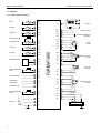
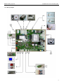
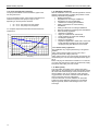
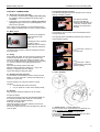
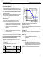
1
Installation- and User Manual
Central Heating Boiler……………………………..…………..35C
Central Heating Boiler……………………………..…………..40C
Wall hung, fan flue, room sealed gas boilers
E000129013
MV030204 manual Atmos EN 35_40 - E000129013 w pump connection
Atmos Heating Systems
Installation and user manual EN_FMT
CONTENTS
CHAPTER 1.
1.1.
1.2.
1.3.
1.4.
1.4.1
1.4.2.
1.5.
1.6.
1.6.1.
1.6.2.
1.6.3.
1.6.4.
1.7
1.8.
1.9.
1.10.
1.11.
1.12.
1.13.
1.13.1.
1.13.2.
1.14.
1.15.
1.16.
Technical data 15B; 15C; 30K; 30B; 30C...............................................................................................
Dimensional sketch................................................................................................................................
Unit components.....................................................................................................................................
Diagrams..................................................................................................................................................
Functional flow diagram...........................................................................................................................
Verkabelungsplan...................................................................................................................................
Operation ...............................................................................................................................................
Boiler types............................................................................................................................................
Atmos 30K..............................................................................................................................................
Atmos 15B / 30B.....................................................................................................................................
Atmos 15C / 30C .................................................................................................................................
Difference between type 15 and type 30................................................................................................
Conditions of delivery.............................................................................................................................
Configuration of flue tube and air supply....................……………………….......………………..............
Environmental conditions.......................................................................................................................
Permitted flue resistance..........................................................................................................................
Heating of central heating water (all models).........................................................................................
Pump and hydraulic resistance ..............................................................................................................
HWS.......................................................................................................................................................
Heating of hot water (Combi-Boiler) ………………........…………………………………………...............
Heating of HWS (boiler with external storage cylinder) .........................................................................
Standards / Guidelines............................................................................................................................
General satety regulations.....................................................................................................................
Water quality...........................................................................................................................................
5
5
6
7
8
8
9
10
10
10
10
10
10
11
11
11
11
11
12
12
12
12
12
12
12
CHAPTER 2. INSTALLATION
2.1.
Mounting the rear cabinet with expansion vessel...................................................................................
2.2.
Mounting the assembly bracket..............................................................................................................
2.3.
Water ans gas connections....................................................................................................................
2.3.1. Gas connection......................................................................................................................................
2.3.2. Central heating water connections..........................................................................................................
2.3.3. HWS connetionto the Combi-boiler.......................................................................................................
2.3.4. Hot water connection to boiler with external storage HWS cylinder........................................................
2.4.
Seal on the waterside.............................................................................................................................
2.5.
Draconin connection................................................................................................................................
2.6.
Electricity connection.............................................................................................................................
13
13
13
14
14
14
14
14
14
14
14
CHAPTER 3. SUSPENDING THE UNTI
3.1.
The unit ..................................................................................................................................................
3.2.
Suspension............................................................................................................................................
3.3.
Fitting the flue tube and air supply.........................................................................................................
3.3.1. Connenting the eccentric flue and air supply (2-pipe system)...............................................................
3.3.2. Connecting the concentric flue tube and air supply (80/125 mm adapter).............................................
3.3.3. Connecting the concentric flue tube and air supply (60/100 mm adapter).............................................
3.4.
Condensation water drain/overpressure protection on drain..................................................................
3.5.
Connection block....................................................................................................................................
3.5.1. On/off room thermostat (if applicable). Connect to terminals (1) and (2)...............................................
3.5.2. Modulating room thermostat (if applicable) . Connect to terminals (1) and (2)......................................
3.5.3. Connection for the external temperature sensor (if appicable) Connect to terminal (3) ans (4).............
3.5.4. Connection of the temperature sensor for the external HWS cylinder. Connect to terminal (5) and (6)
3.6.
Assembling the connection block...........................................................................................................
3.7.
Placing the jacket...................................................................................................................................
15
15
15
15
15
15
15
15
15
15
15
16
16
16
16
CHAPTER 4. COMMISIONING
4.1.
Electrical power.......................................................................................................................................
4.2.
Main switch.............................................................................................................................................
4.3.
Filling......................................................................................................................................................
4.4.
Reading the water pressure...................................................................................................................
4.5.
Venting...................................................................................................................................................
4.6.
Chimney sweeper function.....................................................................................................................
4.7.
Gas / Air Ratio........................................................................................................................................
4.8.
Gas / Air adjustment (CO2 analysing).....................................................................................................
4.8.1. Full load..................................................................................................................................................
17
17
17
17
17
17
17
17
18
18
2
Atmos Heating Systems
4.8.2.
4.9.
4.10.
4.10.1.
4.11.
4.11.1.
4.11.2.
4.11.3
4.12.
Installation and user manual EN_FMT
Low load..................................................................................................................................................
Placing the jacket...................................................................................................................................
Changing over to LPG-gas....................................................................................................................
Full load om Propane.............................................................................................................................
Display...................................................................................................................................................
Normal operation (permanent status indication)....................................................................................
blocking operation (permanent status indication)..................................................................................
Lock-out (flashing status indication).......................................................................................................
Menu structure.......................................................................................................................................
18
18
18
18
19
19
20
20
21
CHAPTER 5. TEMPERATURE REGULATIONS
5.1.
Central Heating...........................................................................................................................................
5.1.1. Central heating temperature regulation with on/off thermostat without outside temperature sensor.........
5.1.2. Central heating temperature regulation with on/off thermostat with outside temperature sensor..............
5.1.3. Central heating temperature regulation with modulating thermostat with or without outside tempsensor..
5.2.
HWS temperature regulations....................................................................................................................
5.2.1. Combi-boiler...............................................................................................................................................
5.2.1.1. HWS heat demand.....................................................................................................................................
5.2.1.2. End of hot water heat demand...................................................................................................................
5.2.1.3. Store heat demand.....................................................................................................................................
5.2.1.4. End of store demand..................................................................................................................................
5.2.2. Boiler with external HWS cylinder..............................................................................................................
5.2.2.1. HWS cylinder with external sensor without modulating space unit............................................................
5.2.2.2. HWS cylinder with external sensor with modulating space unit..................................................................
5.2.3. HWS cylinder with thermostat without modulating space unit....................................................................
5.2.4. HWS cylinder with thermostat with modulating space unit.........................................................................
22
22
22
22
22
23
23
23
23
23
23
23
23
23
23
23
CHAPTER 6 BURNER STATES and MONITORING
6.1.
Burner states..............................................................................................................................................
6.1.1. Rest state...................................................................................................................................................
6.1.2
Purging/Prestart.........................................................................................................................................
6.1.3. Ignition........................................................................................................................................................
6.1.4. Operation....................................................................................................................................................
6.1.5. Post-ventilation...........................................................................................................................................
6.1.6. Functional locking.......................................................................................................................................
6.2.
Monitoring...................................................................................................................................................
6.2.1. Monitoring the pump circulation..................................................................................................................
6.2.2. Pump programm.........................................................................................................................................
6.2.3. Pump test programm..................................................................................................................................
6.2.4. Static pressure monitoring..........................................................................................................................
6.2.5. Difference in temperature...........................................................................................................................
6.2.6. Maximum temperature limitation................................................................................................................
6.2.7
Flue gas temperature limitation..................................................................................................................
6.2.8. Flow sensor protection...............................................................................................................................
6.2.9. Frost protection..........................................................................................................................................
6.2.10. Monitoring the fan speed............................................................................................................................
6.2.11. Glow plug protection...................................................................................................................................
24
24
24
24
24
24
24
24
24
24
24
24
25
25
25
25
25
25
25
25
CHAPTER 7. MAINTENANCE
7.1.
Annual maintenance..................................................................................................................................
7.1.1. Checking the CO2 percentage on full load................………………………………………………………….
7.1.2. Measuring the load on the unit .................................................................................................................
7.1.3. Checking the condensation water drain.......……………………………………………………………………
7.1.4. Ionisation probe..........................................................................................................................................
7.1.5. Water pressure...........................................................................................................................................
26
26
26
26
26
26
26
CHAPTER 8. MALFUNCTIONS
8.1.
Draining the unit.........................................................................................................................................
8.2.
No signal on the display.............................................................................................................................
8.3.
Fault code U/d or U/O (alternating U with a status code will appear on the display...................................
8.4.
Unit does not respond to central heating heat demand..............................................................................
8.5.
Unit does not respond to HWS demand......................................................................................................
8.6.
Three-way-diverter valve............................................................................................................................
8.7.
Check function of gas control.....................................................................................................................
8.8.
Measuring the fan impedance....................................................................................................................
8.9.
Fitting instructions for the pressure sensor................................................................................................
27
27
27
27
27
27
27
27
27
27
3
Atmos Heating Systems
8.10.
8.11.
8.11.1.
8.11.2.
8.11.3.
8.11.4.
8.11.5.
8.11.6.
8.11.7
Installation and user manual EN_FMT
Fitting instructions for the safety valve.......................................................................................................
Malfunction code „F“ (flashing)...................................................................................................................
Gas control will not open (no voltage).......................................................................................................
Gas control will not open (gas inlet pressure too high)..............................................................................
Gas control will not open (coils defective)...................................................................................................
Gas/Air mixture is not correctly adjusted....................................................................................................
Check glow plug.........................................................................................................................................
Check ionisation current.............................................................................................................................
inspection / cleaning / replacement of the ionisation probe........................................................................
28
28
28
28
28
28
28
28
29
User manual
General......................................................................................................................................................................
Cleaning the unit.......................................................................................................................................................
Holidays....................................................................................................................................................................
Brrrr, the central heating is not working....................................................................................................................
Electricity and gas.....................................................................................................................................................
Water and air....................... .....................................................................................................................................
Other causes.............................................................................................................................................................
Display.............................................................. .......................................................................................................
Reset button..............................................................................................................................................................
Abbreviated display indications.................................................................................................................................
30
30
30
30
30
30
30
30
31
31
31
4
Atmos Heating Systems
Installation and user manual EN_FMT
CHAPTER 1.
1.1. Technical data 35C / 40C
Boiler type
Gas type
Electrical data
35 / 40
natural gas G20
Mains voltage / Frequency
230 V / 50 Hz
Power consumption (max.)
144 W
Thermostat voltage
Dimensions and
weight
Emission value
Flue gastemperature
Maximum
chimney
resistance
Connections
natural gas G25
24 V
Height
600 mm
Width
360 mm
Depth
300 mm
Weight
35 kg
CO2
10 – 100 ppm
CO (0% 02)
12 – 35 ppm
NOX (0% O2)
10 – 30 ppm
at 80/60ºC
< 70ºC
at 50/30ºC
< 35ºC
Air feed and flue tube together
125 Pa
Gas
Ø 15 mm
CH (flow and return)
Ø 25 mm
Overflow
Ø 15 mm
Air feed and flue
tube system
Eccentric
Ø 60 – 60 mm
Concentric
Ø 80 / 125 mm
Boiler heat
exchanger
Water contents
Sound level
0.8 L
Max. temperature
90°C
Max. Water pressure
3 bar
Pump high
40 dB(A)
Pump low
Certification
30 dB(A)
CE Identification number
CE0063-AT3070
Boiler type
Gas type
Gas technical
data type 35
35
Nominal gas pressure
natural gas G20
natural gas G25
LPG gas G30/G31
20 mbar
25 mbar
37/50 mbar
Heat input CH (gross)
8.1 – 38.5 kW
Heat input CH (net)
7.3 – 34.7 kW
Nominal output CH at 80/60ºC
7.2 – 33.7 kW
Nominal output CH at 50/30ºC
7.9 – 36.1 kW
Efficiency at 80/60ºC (net)
Low load = 98.1 %; High load = 97.2 %
Efficiency at 50/30ºC (net)
Low load = 108.4 %; High load = 104.2 %
Boiler type
Gas type
Gas technical
data type 40
LPG gas G30/G31
40
Nominal gas pressure
natural gas G20
natural gas G25
LPG gas G30/G31
20 mbar
25 mbar
37/50 mbar
Heat input CH (gross)
8.1 – 41.1 kW
Heat input CH (net)
7.3 – 37.0 kW
Nominal output CH at 80/60ºC
7.2 – 36.0 kW
Nominal output CH at 50/30ºC
7.9 – 37.9 kW
Efficiency at 80/60ºC (net)
Low load = 98.1 %; High load = 97.2 %
Efficiency at 50/30ºC (net)
Low load = 108.4 %; High load = 104.2 %
5
Atmos Heating Systems
Installation and user manual EN_FMT
1.2. Dimensional sketch
Free space
There must be sufficient space at the top and bottom to be able to suspend the unit and to be able to connect all feed and drain
pipes. Normally, roughly 300 mm is required.
It is recommended to leave a free space of 150 mm on the left (for servicing reasons) and 50 mm on the right of the unit.
The front of the unit must be easily accessible for servicing at all times.
6
Atmos Heating Systems
Installation and user manual EN_FMT
1.3. Unit components
No
1
2
3
4
5
6
7
8
9
10
11
12
13
14
15
16
17
18
19
20
21
22
23
24
Description
Primary heat exchanger
Manager
Pump
Manufacturer
Coopra
Coopra
Wilo
Coopra article code
n.a.
n.a.
N00S110006
Glow plug
Ionisation probe
Burner type 30 / 40
Vapour tray
Gas valve
Fan
Venturi type 40
Water pressure sensor
Return sensor
Flow sensor
Safety device
Float vent
Saint Gobain
Sapco
Furigas
Coopra
Honeywell
Vibo
Honeywell
Huba
Honeywell
Honeywell
Emmeti
Emmeti
N00S070014
N00S070020
N00S020000
N00S020015
N00S020009
N00S020006
N00S020008
N00S080028
N00S070008
N00S07008
xxxxxxxx
xxxxxxxx
Flue gas temperature sensor
Type plate
Condensation water overflow
Gas connection
Central heating return
Central heating flow
Tasseron
Coopra
Coopra
Coopra
Coopra
Coopra
N00S070017
n.a.
n.a.
n.a.
n.a.
n.a.
7
Atmos Heating Systems
Installation and user manual EN_FMT
1.4. Diagrams
1.4.1. Functional flow diagram
-t
FLOW
X17.6
X12
X17.3
DISPLAY
-t
RETURN
X17.2
X17.5
X22.1
-t
DHW INLET
X4.5
X19.1
X2.5
-t
X18.3
X2.4
X18.1
X2.3
X16.7
X2.2
X16.3
X2.1
-t
FLUE GAS
X16.6
X16.2
WATER PRESSURE
+
X15.2
P
X15.1
-
X15.3
ROOM THERMOSTAT
24VAC
X9.1
X9.2
X10.1
EbV THERMOSTAT
FURIMAT-990
-t
OUTSIDE
X3.5
X3.4
X3.2
X3.1
X4.4
X4.3
X4.1
X8.2
X10.2
X8.6
OPENTHERM
THERMOSTAT
X11.1
PC CONNECTION
X14
X11.2
X8.5
X8.4
X8.3
ROOM THERMOSTAT
230VAC
230V 50 Hz
X8.1
X1.3
X6.3
X7.4
X7.2
X6.1
L1
L2
PUMP
230 VAC
L3
N
PE
DHW
CH
THREE-WAY VALVE
230 VAC
N
PE
L
GAS VALVE
230 VRAC
N
PE
F1
+
FSP
COMBUSTION FAN
325 VDC
F2
PE
IONISATION
GLOW IGNITER
N
L
BURNER
X7.1
PE
8
X1.4
X6.4
L
N
PE
MAXIMAL THERMOSTAT
(OPTIONAL)
X4.6
TANK THERMOSTAT
EXTERNAL TANK
ALARM CONTACT
X22.2
X19.2
PE
Atmos Heating Systems
Installation and user manual EN_FMT
1.4.2. Wiring diagram
9
Atmos Heating Systems
1.5. Operation
Installation and user manual EN_FMT
1.7. Specific caracteristics type 40
1.7.1. Burner assy N00S020000
1.7.2. Primair heat exchanger N00S040005
A fan sucks the air required for the combustion through the
air feed canal (A). Because the combustion air in the
venturi sucks an under pressure, the correct amount of gas
(G) is automatically added to the combustion air.
The flammable gas/air mixture thus obtained is fed to the
burner, via a mixing chamber, to be ignited at the surface of
the burner by a ceramic glow plug. The hot combustion
gases are efficiently fed through the heat exchanger, where
they give their heat to the water. The flue gases are fed
outside, through the flue tube (F), into a flue tube exhaust
canal.
The condensation water (H2O) thus obtained is discharged
into the sewer.
1.7.3. Venturi N00S020008
1.6. Boiler types
Atmos 40C
High efficiency boiler for central
heating only.
1.7.4. Pump N00S110006
The Atmos boiler is a heating unit with compact dimensions
and a very high efficiency, with versions for domestic and
small commercial use for central heating.
The type plate, which specifies the type of gas etc. to be
used, for which the unit is set, is on the left side of the unit.
The unit is fixed to the wall with the aid of a separately
delivered assembly bracket or rear cabinet.
1.8. Conditions of delivery
Coopra Advanced Heating Technologies b.v. supplies its
products according to the general conditions of delivery for
the metal and electro technical industry. Registered with the
Clerk of the District Court at Den Haag on 19 October 1998
under no. 119/1998.
10
Atmos Heating Systems
1.8. Configuration of flue tube and air supply
See figure below for an overview of possible configurations.
The units are approved for application on the drain
systems:
B23, C13(x), C33(x), C43(x), C53, C63(x), C83(x).
Preferably use flue tube materials, roof ducts and exterior
wall ducts with a quality mark.
With plastic drain materials, use a unit with a flue gas
temperature sensor.
Installation and user manual EN_FMT
1.9. Environmental conditions
The area in which the unit is installed must satisfy the
applicable regulations.
The wall must be able to bear the weight of the unit (loaded
weight approx. 40 kg).
If you use a different assembly surface than a bricky wall of
sufficient thickness, you must select suitable fixtures
yourself and properly install the unit.
The unit may not be fitted in a chemically aggressive
environment.
The unit with air feed and flue gas exhaust satisfies the
requirements of protection class IP44 and may therefore be
installed in a wet area.
Although the unit is fitted with an internal frost protection, it
may not be exposed to extremely low ambient
temperatures (lower than -10°C).
1.10. Permitted flue resistance
The total resistance of the flue tube and air supply together
may not be greater than 125 Pa.
Indication for the resistance values given in table below
3
apply to a flow rate of 60 m /hour.
dia. 80 mm
Tube per metre
5.0 Pa
Bend 90°, R = 1.5 D
6.5 Pa
Bend 90°, R = 0.5 D
15.0 Pa
Bend 45°, R = 1.5 D
4.0 Pa
Bend 45°, R = 0.5 D
Roof duct (concentric,
1.25 m)
5.5 Pa
30.0 Pa
1.11. Heating of central heating water
If the room thermostat or space unit indicates that heat is
required for the central heating, the unit will heat the central
heating water as necessary. The power supplied is
automatically adapted to the heat required and is also
continuously variably adapted to the heat demand with the
use of an on/off thermostat.
When the thermostat indicates that the desired temperature
has been reached, the central heating water is no longer
heated. The central heating pump will continue to run for a
previously set time to distribute the heat evenly over the
heating installation.
A differential bypass valve must be installed on plants
where it may happen that various radiators are
simultaneously excluded from the circuit because of
closure of control or zone valves.
The by-pass valve must be mounted in the installation
between the flow and the return, provided that flow
direction indicated by arrow is respected.
To adjust the by-pass valve rotate knob of the graduated
scale on setting 2.5-3.0. This value corresponds to the
meters of pump head (m H2O).
Lock the screw on the groove knob.
11
Atmos Heating Systems
Installation and user manual EN_FMT
1.12. Pump and hydraulic resistance
The pump characteristic and the resistance graph of the
unit are given below.
1.14. Standards / Guidelines
With the installation of the unit, all local regulations must be
followed, where applicable, including the provisions of the
following standards and guidelines:
•
Building Regulations
•
Regulations for natural gas installations
•
Regulations for LPG (if applicable)
•
Guidelines for existing gas installations
•
Safety requirements for central heating
installations
•
Safety provisions for low voltage installations
•
General regulations for drinking water installations
•
Water authority regulations
•
Ventilation in dwellings
•
Supply of combustion air and exhaust
•
House sewerage in homes and dwellings
•
Fire Brigade regulations
•
Factory Act regulations
•
Regulations applicable to HWS water Ask for the
locally applicable regulations at the local water
company as they are different in some areas
If set on automatic function (menu setting) the electronics
switches the speed of the pump to “high” or “low”,
depending on the temperature demand:
•
•
Dt > 30 °C : the pump runs „high speed“.
Dt < 10 °C : the pump runs „low speed“.
Dt = Setpoint temperature deducted with the actual Flow
temperature.
0,8
Pump state high
0,7
Pressure [bar]
0,6
0,5
Pump state low
0,4
0,3
Boiler resistance
0,2
0,1
0
0
0,2
0,4
0,6
0,8
1,0
1,2
1,4
1,6
Flow [m³/h)]
1,8
2,0
2,2
2,4
2,6
2,8
3,0
1.15. General safety regulations
The installation may only be performed by a recognised
installer.
Take note that internal parts of the unit can carry a
dangerous electrical voltage (230 Volt).
Take note that the unit, the various pipes and the flue gas
exhausted by the unit can reach high temperatures (up to
90°C).
Before carrying out maintenance activities in or on the unit,
you must close the gas tap, switch off the electricity supply
and pull the mains plug out of the socket.
1.16. Water quality
The composition and quality of the system water has a
direct effect on the performance of the total system and the
life of the boiler heat exchanger. Great care must be used
with the addition and use of chemicals, water softeners,
oxygen binders, de-aerators, aerators and water filters as
they increase the chance of malfunctions.
Corrosive elements of certain additives can attack the
system and cause leakages; the build-up of undesired
deposits generally leads to fatal damage of the heat
exchanger.
12
Atmos Heating Systems
CHAPTER 2. INSTALLATION
Installation and user manual EN_FMT
2.2. Mounting the assembly bracket
To mount the assembly bracket on a brick wall of sufficient
thickness, use the screw plugs that are supplied. When you
have determined the place of assembly, proceed as
follows:
1. Draw the position of the hole (1) in the strap of the
assembly bracket.
2. Use a masonry drill of 8 mm diameter to drill a hole with
a sufficient depth in the wall.
3. Keep the hole (1) in the assembly bracket in front of the
hole in the wall and fit one of the screws supplied
through the assembly bracket in the hole.
4. Align the assembly bracket with the aid of a spirit level.
5. Use a masonry drill of 8 mm diameter to drill holes with a
sufficient depth in the wall through the two bottom holes
(2) in the assembly bracket.
6. Fit two of the screws supplied in the bottom holes.
7. When using assembly brackets with ac lamping plate for
eccentric flue tube and air feed connection:
Use a masonry drill of 8 mm diameter to drill a hole
with a sufficient depth in the wall through the hole
in the clamping plate and fit a nail plug in this hole.
Fit the clamping plate at right angles.
8. Fix the assembly bracket firmly by tightening all screws.
13
Atmos Heating Systems
2.3. Water and gas connections
Installation and user manual EN_FMT
2.3.2. Central heating water connections
•
Connect the central heating flow pipe to
connection (2.
•
Connect the central heating return pipe to
connection (1.
•
A differential bypass valve must be installed on
plants where it may happen that various radiators
are simultaneously excluded from the circuit
because of closure of control or zone valves.
•
Install a filling and draining device in the central
heating system. Do not use the overflow valve as
a drain. The overflow valve is a safety valve that
ensures that the system is not subjected to a too
high pressure (max 3.0 bar).
•
Stopcocks must be fitted in the central heating
flow pipe (2) and the central heating return pipe
(1).
•
The central heating return pipe (1) must be fitted with
a suitable expansion vessel. The size of the
expansion vessel must be determined on the basis of
the central heating water temperature and the total
water content the installation contains.
•
•
If it may be expected that the central heating
water will be severely contaminated by under floor
heating, fitting is a 2 kg dirt filter in the return pipe
is recommended. Atmos cannot give a guarantee
for damage to the unit that is caused by dirt in the
system.
Before connecting the boiler unit, rinse the system
completely to remove all contamination.
2.4. Seal on the waterside
With the use of the group of taps, you can now make a
check on the seal on the waterside of the system.
2.3.1. Gas connection
•
Connect the gas pipe to connection (5).
•
Install the gas pipe stress free.
•
Include an approved stopcock in the pipe.
•
Carefully blow the gas pipe clean.
2.5. Draconin connection
There must be a connection for the removal of the
condensation water to the drain. This connection must be
fitted with a trap to prevent smell problems.
A tundish connection must be made because of possible
overpressure or underpressure in the drain.
Fit the condensation drain pipe (6) (inner diameter 40 mm
minimum) several centimetres left of the gas pipe.
2.6. Electricity connection
There must be an electrical outlet with earth connection
available at a maximum distance of 1 m from the unit.
The electricity connection (230 VAC) must consist of live,
neutral and earth
A good earth connection is a requirement for good
operation of the unit.
14
Atmos Heating Systems
CHAPTER 3. SUSPENDING THE UNIT
3.1. The unit
Before unpacking the unit, check
whether the type of gas to be used
corresponds with the specification
on the packing. If you have any
questions, contact your supplier.
To prevent back injury, take
account of the fact that the weight
of the unit is roughly 35 kg.
3.2. Suspension
Place an O-ring in the middle of each of the connections
present (1) - (5).
Remove the caps from the pipes of the unit.
Keep the unit straight against the wall at about 5 cm above
the site of the mounted assembly bracket or the assembly
cabinet.
Press the unit into the guide and let it drop carefully, so that
the hook on the suspension bracket falls into the opening at
the rear of the unit and the pins at the bottom of the unit fall
in the corresponding openings in the suspension bracket.
Here, the connection pipes of the unit fall over the
connection points of the suspension bracket.
Firmly tighten the union nuts of each of the connections
present (1) to (5) with the aid of a spanner.
Installation and user manual EN_FMT
that the clamping plate falls in the groove of the sliding
piece.
3.3.2. Connecting the concentric flue tube and air
supply (80/125 mm adapter)
When the flue tube and air supply are connected
concentrically, proceed as follows:
1. Fit the 80/125 mm adapter on the unit before you place
the unit.
2. After you have placed the unit, fit the concentric pipes on
the 80/125 mm adapter.
3.3.3. Connecting the concentric flue tube and air
supply (60/100 mm adapter)
When the flue tube and air supply are connected
concentrically, proceed as follows:
1. Fit the 60/100 mm adapter on the unit before you place
the unit.
2. After you have placed the unit, fit the concentric pipes on
the 60/100 mm adapter.
3.4. Condensation water drain/overpressure protection
on drain
Make a tundish between the condensation water
drain/overpressure protection of the unit and the drainpipe.
3.5. Connection block
The connections of the green connection block are all voltfree contacts. Therefore, do not connect 230 Volts to them!
3.3. Fitting the flue tube and air supply
terminals (1) - (2)
Connection for 24 Volt thermostat
terminals (3) - (4)
Connection for 12 kOhm external
temperature sensor
terminals (5) - (6)
Connection for 10 kOhm or 12 kOhm
sensor of external cylinder
If no on/off room or modulating room thermostat is used at
all, terminals (1) and (2) must be connected by wire.
3.3.1. Connecting the eccentric flue and air supply (2pipe system)
When the flue tube and air supply are connected
eccentrically, proceed as follows:
1. Fit the flue tube in the opening, in the suspension
bracket.
2. Let the pipe protrude 30 -35 mm under the clamping
plate.
Slide the sliding piece (1) upwards over the flue tube.
3. Fit the air supply in the opening in the suspension
bracket.
4. Let the pipe protrude 40 - 45 mm under the clamping
plate.
5. Fit the rubber bellows over the air supply pipe and seal
them with the hose clip.
6. Fit the clamping plate on the suspension bracket and
tighten it with the three screws supplied. Take care here
3.5.1. On/off room thermostat (if applicable).
Connect to terminals (1) and (2)
The on/off room thermostat (24 V) must be fitted in the
same building as the unit.
Strip about 5 mm off the insulation of the wires of the room
thermostat. Stick the stripped ends of the wires into
connections (1) and (2) of the connection block. Make sure
that the wires do not make a short circuit. Firmly tighten the
screws in the connection block.
3.5.2. Modulating room thermostat (if applicable).
Connect to terminals (1) and (2)
The modulating room thermostat must be fitted in the same
building as the unit.
Strip about 5 mm off the insulation of the wires of the room
thermostat. Stick the stripped ends of the wires into
connections (1) and (2) of the connection block. Make sure
that the wires do not make a short circuit. Firmly tighten the
screws in the connection block.
15
Atmos Heating Systems
Installation and user manual EN_FMT
When using a modulating thermostat, the plug on the
printed circuit board must be connected with the correct
polarity.
To reach the printed circuit board, the black casing must be
opened. Connect the plug for the relevant modulating
space unit to terminal a, b or c, according to the following
photograph.
a
b
c
a
White Connection for an on/off
room thermostat
b
Red
Connection for RS30 with EBV space
Coopra protocol
regulation
c
Blue
Opentherm connection
24 Volt
Honeywell or TEM
space regulation
3.5.3. Connection for the external temperature sensor
(if applicable).
Connect to terminals (3) and (4)
If an external sensor is connected, this temperature sensor
must be an NTC with a resistance of 12 kOhm at 25°C.
Strip about 5 mm off the insulation of the wires of the
sensor. Stick the stripped ends of the wires into
connections (3) and (4) of the connection block, see figure
8. Make sure that the wires do not make a short circuit.
Firmly tighten the screws in the connection block.
If an external sensor is not used, terminals (3) en (4) can
remain open.
3.6. Assembling the connection block
Connect the green
connection block in the
green socket.
3.7. Placing the jacket
Place the jacket in the appropriate hooks at the top of the
unit. Let the jacket pivot until it falls over the unit. Tighten
the fastener at the bottom of the jacket.
16
Atmos Heating Systems
Installation and user manual EN_FMT
CHAPTER 4. COMMISSIONING
4.1. Electrical connection 230 VAC
• If the boiler is provided with a supply cord and a plug
the appliance must be positioned so that the plug is
accessible.
• If the boiler is not provided with a supply cord without
a plug the supply must have a contact separation of at
least 3 mm in all poles.
If the supply cord is damaged, it must be replaced by the
service agent or similarly person in order to avoid a hazard.
4.2. Main switch
To power up the appliance
please switch the main
switch on.
4.6. Chimney sweeper function
The chimney sweeper function has priority over the central
heating and HWS regulation.
The chimney sweeper
function is activated by
simultaneously pressing the
"+ and the – buttons" of the
display in for longer than 5
seconds.
The ionisation current can be read in microamperes in the
two right segments.
The capacity that is immediately released is the maximum
central heating capacity.
If the display of the unit gives
the status code ‘U’
(alternately with an arbitrary
other code), this means the
live and neutral
connections are reversed. Isolate the supply and reverse
the connections.
4.3. Filling
During filling with water, the unit must be connected to the
mains and be switched on. Fully open all radiator taps.
Connect the water supply to the filling connection. If the
unit is not yet filled with water, the display shows a flashing
‘P’. The two numbers on the display give the water
pressure.
Open the tap to fill the system with water.
When the water pressure is sufficient (> 1.3 bar), the
flashing ‘P’ disappears from the display.
Close, after filling, the filling tap again.
Press the "- button" to
go to low load.
Press the "+ button"
to switch back to the preset
full load capacity.
4.7. Gas / Air Ratio
4.4. Reading the water pressure
It is possible to read the water pressure directly from the
display. To do this, press the + button of the display for a
minimum of 5 seconds.
The unit switches out of the menu back to normal
operation:
•
automatically after about 5 minutes;
•
or if you press the - button of the display shortly.
4.5. Venting
After filling, the heating installation must be vented.
Proceed as follows:
Follow the instructions from the manufacturer/installer for
the venting of possible other elements of the heating
installation, such as underfloor heating.
Fully open all radiator taps.
Open the air bleed cocks of the radiators one at a time.
Use an air bleed key for this.
As soon as water comes out of the air bleed cock, shut the
cock off again.
(1). Venturi screw – Full load adjustment
Turn the venturi screw anti-clockwise to increase the CO2
value, clockwise to decrease it.
(2). Gas control screw – Low load adjustment
Turn the screw anti-clockwise to decrease the CO2 value
on low load, clockwise to increase it.
(3). Cover screw
17
Atmos Heating Systems
Installation and user manual EN_FMT
Pre-adjustment to be done in voltage-free condition:
LPG GAS – Turn venturi-screw clockwise 3
completely down on its seat.
Then turn the venturi screw anti-clockwise 4
for 2 complete turns.
NATURAL GAS – Turn venturi-screw clockwise 3
completely down on its seat.
Then turn the venturi screw anti-clockwise 4
for 4 complete turns.
PRE- ADJUSTMENT MEASUREMENT:
Distance between Venturi-screw (1) and the Top of the
venturi-stud to be about:
12.5 mm for natural gas G25
14.1 mm for natural gas G20
16,5 mm for LPG gas G31
4.8.2. Low load
Activate the chimney sweeper function on low load
Read the CO2 value on the
analyser. If the value does
not correspond with the
value in the "CO2 setting"
table, carefully adjust the
gas control adjusting screw
(2). To do this, temporarily
remove the cap (3) with the
aid of a Torx screwdriver.
Turn the screw anti-clockwise to decrease the CO2 value
on low load, clockwise to increase it.
At the end of the flue gas analysis, set the central heating
capacity (P) in the menu again to the value that is best
suited for the application.
With a vernier callipers the distance between venturi-screw
(1) and the Top of the venturi-stud (1) has to be measured
to find the rough setting of the venturi screw for full load,
and depending of the used gastype.
The exact adjustment of the setting has to be made using
the CO2 analysing method as described below.
4.9. Placing the jacket
4.8. Gas / Air adjustment ( CO2 analysing)
The gas control is set in the factory to the type of gas to be
used. This type of gas is stated on the packing and on the
identification plate. To check the setting, you have to make
a flue gas analysis.
First: the venturi adjusting screw fully clockwise until
it blocks.
Place the jacket in the appropriate hooks at the top of
the unit. Let the jacket pivot until it falls over the unit.
Tighten the fastener at the bottom of the jacket.
4.10. Changing over to LPG-gas
Fit a flue gas analyser
(CO2 meter) in the
measurement opening of
the flue tube canal.
Proceed as follows
Remove the measuring cap
from the flue tube.
Fit the measurement probe
of a flue gas analyser (CO2
meter) in the measurement
opening of the flue tube
canal.
Make sure there is sufficient
heat dissipation through the
heating.
At full central
heating load
(P=100%)
At low load
Natural gas
8,8-9.4 % CO2
8,2-8,6 % CO2
(G20, G25)
9,8 % CO2
9,2% CO2
4.8.1. Full load
The burner has to burn at maximum central heating
capacity (Menu setting P=100%).
Activate the chimney sweeper function on full load.
Read the CO2 value on the
analyser. If the value does
not correspond with the
value in the "CO2 setting"
table, carefully adjust the
venturi screw (1). Turn the
venturi screw anti-clockwise
to increase the CO2 value,
clockwise to decrease it.
18
Set in the menu the capacity “P” to 100%.
Activate the chimney sweeper function on full load.
CO2 setting
Propane (G31)
4.10.1. Full load on Propane
Unscrew the venturi adjusting screw four full turns anticlockwise.
(A guide for the dimension from the top of the screw to the
top of the support is 16.1 mm).
Read the CO2 value on the flue gas analyser. If the value
does not correspond with the value for propane gas G31
(9,8% CO2), carefully adjust the venturi screw until the
correct value is obtained.
If the gas control is already
properly adjusted for natural
gas, then the low load will
not need to be adjusted.
Activate the chimney
sweeper function on low
load.
Check the CO2 value at
minimum capacity for propane gas G31 (9.2% - 9.5% CO2).
If necessary, adjust the gas regulator screw until the
correct value is obtained. Note that this setting is a critical
one.
Atmos Heating Systems
4.11. Display
A = display
B = + button
C = Set / Reset
D = Status display
E = - button
Installation and user manual EN_FMT
During operation, the display shows the status of the
unit in the form of a code. To be able to read the codes,
open the cover in front of the display. The display
consists of three 7-segment LED’s + three decimal
points and three pushbuttons.
The left 7-segment LED shows the status or the menu
step.
The two right 7-segment LED's show the temperature,
the pressure or the parameter value.
4.11.1. Normal operation (permanent status indication)
The Normal operation is to indicate the burner action.
-Initialisation after restoration of supply power
O
No heat demand, stand-by
C
Central heating heat demand, burner off
C.
Central heating heat demand, burner on
P/C.
Central heating heat demand, low load water pressure
A/C.
Central heating heat demand, low load chimney temperature
c
Central heating pump post-running
b
Burner off / post-running of pump for external HWS cylinder
b.
Burner on
P/b.
Boiler, low load by water pressure
A/b.
Boiler, low load by chimney temperature
O
Frost protection burner off pump running 8C
o.
Frost protection burner on 3C
C (flashing)
Chimney function (temp display max/min/ionisation)
4.11.2. Blocking operation (permanent status indication)
The burner stopped burning due to an incorrect situation. The display gives a permanent indication (not flashing) and the
operation can be restored by switching it off and on (volatile block).
U/
Power supply line not correctly connected
Reversed neutral and line
code
Faulty flow sensor
1
Flow sensor open circuit
Wiring interrupted or not correctly connected
Faulty flow sensor
1.
Flow sensor short circuit
Faulty wiring
Faulty return sensor
2
Return sensor open circuit
Wiring interrupted or not correctly connected
Faulty return sensor
2.
Return sensor short circuited
Faulty wiring
Faulty flue gas sensor
4
Flue gas sensor open circuit
Wiring interrupted or not correctly connected
6
Cold water sensor open circuit
n.a.
6.
Cold water sensor short circuited
n.a.
A
Flue gas temperature > 80°C
The burner is reduced to low load
H
Flow sensor > 105°C while the burner was off
Reset the supply power by the on/off switch
E
Internal error
Reset the supply power by the on/off switch
Check the central heating system pressure
P
Pump test / Start function blocking / Water pressure Seized or faulty pump or faulty pump wiring
Faulty pressure sensor or wiring
nc
Burner Manager fault
Reset the supply power by the on/off switch
4.11.3. Lock-out (flashing status indication)
In case of lock-out the display gives a flashing indication and the operation can be restored by pressing the reset button, placed
on the control panel.
1
Boiler does not pass start temperature test
Check system water flow; second system pump
2
Too many restarts
Internal regulation fault / A/D conversion fault /
3
external sensor fault /Too many restarts
5
Fan fault
7
Gas valve fault
8
Flame detected with closed gas valve
Check gas valve
A
Flue gas temperature > 95°C
Check why flue gas becomes temperature > 95°C
E
Internal interlock fault
Reset the supply power by the on/off switch
H
Flow sensor > 105°C with burner on
Check system water flow
F
Too many ignition attempts
O
Gas valve connection
Check short cut wire on print board terminal X4
19
Atmos Heating Systems
Installation and user manual EN_FMT
4.12. Menu structure
By pressing the set/reset button in for longer than 5 seconds, you go to the ‘mode’ menu.
To change the subsequent "Letter" parameter, the user must press the Set/Reset button.
To change the “Range” setting in the parameter, the user must press the “+” or the “–“ button.
Letter
Description
Range
Factory setting
C
max. set point of central heating
25°C - 90°C
82°C
O
Central heating post-running time
1 - 25 min, CO = 24 hours
5 min
P
Max central heating capacity
33 – 100 %
80 %
Field of application
0 = central heating unit
1 = n.a.
H
Type of application
2 = for external HWS cylinder 12kOhm
unit-dependent
unit-dependent
40°C -70°C
60°C
external storage
vessel
10 -70°C
20°C
1-100
20
0°C -70°C
20°C
3 = for external HWS cylinder 10kOhm
4 and 5 = all functions are blocked
d
t
b
O/b
O/S
O/d
r
Set point for storage HWS cylinder
Basic temperature
External characteristic
Slope
External characteristic
Day reference temperature
Factory setting
= Factory setting
= Changed factory setting
If you switch back to the factory setting,
this has no effect on the H, S and P/S
settings
00 = automatic
S
Pump speed
= always high
00 = automatic
= always low
= 0.54
P/S
Maximum pressure jump
= 0.53
= 0.52
In the View mode, you can read the actual values of:
8 = Water pressure (in bar)
1 = Flow temperature (in °C)
2 = Return temperature (in °C)
3 = Inlet cold water temperature / HWS sensor (in °C)
4 = External temperature (in °C)
5 = Outside temperature (in °C)
6 = Flue gas temperature (in °C)
7 = Flame signal (in µA DC)
9 = Last interlock
A = Last blocking
20
These three settings
are only active when
an external sensor is
connected
= 0.54
Atmos Heating Systems
Installation and user manual EN_FMT
Heating curve
5.1. CENTRAL HEATING
The permissible central heating flow temperature can be set
between 40°C and 90°C. The burner is blocked when the set
flow temperature is reached. During the first 60 seconds of a
central heating heat demand, the flow temperature may rise to
3°C above the set point before the regulation locks.
5.1.1. Central heating temperature regulation with on/off
thermostat without outside temperature sensor
Increasing set point
When the room thermostat is closed (heat demand), the set
point (desired central heating flow temperature) rises at a rate
of 2°C per minute until the maximum permissible central
heating flow temperature is reached (21 minutes from
minimum 40°C to 82°C).
Falling set point
When the room thermostat is open (end of heat demand), the
set point (desired central heating flow temperature) falls at a
rate of 4°C per minute to the minimum central heating
temperature (10.5 minutes from 82°C to minimum 40°C).
Burner is on
•
when the room thermostat is closed (heat demand)
•
and when the actual flow temperature is 5°C below
the set point (desired central heating flow
temperature)
•
and after 3 minutes anti-reciprocital time, if
applicable
Burner is off
•
when the room thermostat is open (end of heat
demand)
•
when the actual flow temperature is 3°C above the
set point (blocking)
•
or when the actual flow temperature is 3°C above the
maximum permissible central heating temperature.
During the set central heating post-running time, the pump will
continue to run over the central heating circuit in low load.
5.1.2. Central heating temperature regulation with on/off
thermostat with outside temperature sensor
Set point
The desired central heating flow temperature (set point) is
calculated on the basis of the measured outside temperature
and the [O/S] - [O/d] - [O/b] parameters set in the menu.
In formula form:
Set point of central heating = (20°C – outside
temperature)*[O/S] /10 + [O/d]
Letter
in
Description
menu
O/b
Basic temperature
O/S Slope
O/d
Flow temperature at
outside = 20°C
C
Max. Flowtemp. for
central heating
Range
default
10 –70 °C
1 – 100
0 –70 °C
20 °C
20
20°C
25 –90 °C
82°C
Supply temperature [°C]
CHAPTER 5. TEMPERATURE REGULATIONS
Parameter C=82°C [default]
O/S=20 [default]
O/d=20°C [default]
O/b=20°C [default]
Outside temperature in °C
Outside temperature [°C]
O/b-value: The setting of the minimal Heating flow
temperature ( value in °C).
O/S-value : The setting for the sloop of the curve.
( change of Flow temperature depending on the change of the
outside temperature).
O/d-value : The setting of the flow temperature at an outside
temperature of 20°C ( value in °C).
Parameter „C“
The setting in the menu „C“ makes the maximal heating flow
temperature ( default 82°C).
Burner is on
•
when the room thermostat is closed (heat demand)
•
and when the actual flow temperature is 5°C below
the set point (desired central heating flow
temperature)
•
and after 3 minutes anti-reciprocital time, if
applicable, after a reciprocital stop
Burner is off
•
when the room thermostat is open (end of heat
demand)
•
when the actual flow temperature is 3°C above the
set point (blocking)
•
or when the actual flow temperature is 3°C above the
maximum permissible central heating temperature.
During the set central heating post-running time, the pump will
continue to run over the central heating circuit in low load.
21
Atmos Heating Systems
5.1.3. Central heating temperature regulation with
modulating thermostat (EBV or Opentherm) with or
without outside temperature sensor
Set point
The set point indicates whether there is a heat demand.
- Without an outside temperature sensor, the desired central
heating flow temperature (set point) is calculated by the
modulating room thermostat.
- With an outside temperature sensor, the measured outside
temperature is sent to the modulating room thermostat,
which uses it to calculate the desired central heating flow
temperature (set point).
Burner is on
•
when the room thermostat is closed (heat demand)
•
and when the actual flow temperature is 5°C below
the set point (desired central heating flow
temperature)
•
and after 3 minutes anti-recycling time, if applicable
Burner is off
•
when the room thermostat is open (end of heat
demand)
•
when the actual flow temperature is 3°C above the
set point (blocking)
•
or when the actual flow temperature is 3°C above the
maximum permissible central heating temperature.
During the set central heating post-running time, the pump will
continue to run over the central heating circuit in low load.
5.2. HWS temperature regulations
5.2.2. Boiler with external HWS cylinder
The regulation is made on the basis of flow temperature with
a normal cylinder thermostat function, on off.
5.2.2.1. HWS cylinder with external sensor without
modulating space unit
The unit switches the heating of the storage HWS cylinder off
when the return sensor has reached the desired final
temperature of the HWS cylinder.
There is a burner demand when the flow temperature is lower
than 85°C and the return temperature is lower than the
desired HWS cylinder temperature.
With HWS cylinder heat demand, the pump state is high.
5.2.2.2. HWS cylinder with external sensor with
modulating space unit
The modulating thermostat will generate a desired HWS
temperature value.
The unit switches the heating of the cylinder off when the
return sensor has reached the desired final temperature of the
HWS cylinder.
There is burner demand when the flow temperature is lower
than 85°C and the return temperature is lower than the
desired HWS cylinder temperature.
With HWS cylinder heat demand, the pump state is high.
22
Installation and user manual EN_FMT
5.2.3. HWS cylinder with thermostat without modulating
space unit
There is HWS cylinder heat demand when the HWS cylinder
thermostat is closed.
The unit switches the heating of the HWS cylinder off when
the return sensor has reached the desired final temperature of
the HWS cylinder
There is burner demand when the flow temperature is lower
than 85°C and the return temperature is lower than the
desired HWS cylinder temperature.
With HWS cylinder heat demand, the pump state is high.
5.2.4. HWS cylinder with thermostat with modulating
space unit
The modulating thermostat will generate a desired hot water
temperature value.
There is heat demand when the HWS cylinder thermostat is
closed.
The unit switches the heating of the HWS cylinder off when
the return sensor has reached the desired final temperature of
the HWS cylinder.
There is burner demand when the flow temperature is lower
than 85°C and the return temperature is lower than the
desired HWS cylinder temperature.
With HWS cylinder heat demand, the pump state is high.
Atmos Heating Systems
CHAPTER 6. BURNER STATES / MONITORING
6.1. Burner states
6.1.1. Rest state
Fan off - Gas valve off - Igniter off - Ionisation off
During the rest state, a check is made to see if there is burner
demand.
If a false flame signal is detected during the rest state for
more than 5 seconds, the Manager locks. If the glow plug
counter is too high (too many Starts), the regulation blocks the
burner demand.
If there is burner demand and no blocking, the system will go
over to purging/preheating.
6.1.2. Purging/Prestart
Fan off - Gas valve off - Igniter off - Ionisation off
The fan is switched on at the desired purging speed. The glow
plug is switched on at the same time as the fan.
After a few seconds, the fan goes from purging speed to the
faster ignition speed.
If a false flame signal is detected during purging, the
regulation locks.
If this lock is present for more than 5 seconds, the regulation
locks with ‘8’:
6.1.3. Ignition
Fan on - Gas valve on - Igniter on/off - Ionisation off/on
The fan is running at the ignition speed.
The gas valve is activated.
The Glow plug will be switched off as soon as an ionisation
signal is measured.
If there is no ionisation at the end of the safety time, a new
attempt at ignition will be made if this was not the last
permitted attempt at starting. Here, there will first be postignition failure ventilation see 8.5.
If there is ionisation at the end of the safety time, the system
continues with operation:
6.1.4. Operation
Fan off - Gas valve off - Igniter off - Ionisation on
The fan is running at the required modulation speed.
If the ionisation fails, a restart is made, providing this is not
the third time within the burner demand. If this is the third
time, the Manager will lock.
The restart runs through post-ventilation purge, see 8.5.
If the burner demand ends, the system goes to postventilation purge, see 8.5.
6.1.5. Post-ventilation
Fan on - Gas valve off - Igniter off - Ionisation off
The fan runs at the last demanded speed if the postventilation is running at the end of the burner demand and in
all other cases at the highest speed.
If a false flame signal is detected during purging, the
regulation locks.
If this lock is present for more than 5 seconds, the regulation
locks with ‘?’:
With end of post-ventilation purging after the end of the burner
demand, a start test is run through:
Installation and user manual EN_FMT
6.1.6. Functional locking
Fan on/off - Gas valve off - Igniter off - Ionisation off - Alarm
contact on
During functional locking, the pump is on the central heating
circuit.
At the beginning of the interlock, in the fault table is updated
With some instances of interlock, the fan will post-ventilate for
1 minute at 50% of the maximum speed.
6.2. Monitoring
6.2.1. Monitoring the pump circulation
The pump is switched off for 3 seconds for each burner start.
At the same time, the purging/prestart time starts. The static
pressure is measured. After this, the pump is switched to a
high speed. The purging time starts as soon as the pump
speed has reached the desired value. At the end of the
purging/prestart time, the active pump pressure is measured.
If the difference between the active and the static pump
pressure is less than 0.05 bar, the regulation locks and goes
to the pump test program.
If the difference is more than 0.54 bar, the regulation locks
and goes to the pump test program.
If the difference is between 0.05 and 0.54 bar, the ignition
time starts.
When the pump is switched to the low state during ignition,
the pressure increase monitoring is switched off.
After the ignition time, the flow monitoring is realised by the
flow/return sensor.
If the temperature rise is large enough, the pump modulation
is released.
If the pressure changes afterwards by more than ± 0.1 bar (±
0,27 bar with changing pump speed) within 4 seconds, the
regulation will block and switch over to the pump test
program.
With switching over from central heating to hot water during
operation, the pressure fluctuation detection is defeated for 16
seconds.
6.2.2. Pump program
If the temperature difference between flow and return is
greater than 30°C, the pump switches to a high speed. When
the temperature difference drops below 10°C again, the pump
switches back to a low speed.
If the pump is on for a HWS demand with a Combi-unit or for
cylinder heat demand, the pump is continuously at high.
6.2.3. Pump test program
The pump is switched off for 15 seconds and high for 15
seconds. The display shows ‘P’.
The initial pressure is measured before the pump is switched
on. The test pressure is measured 3 seconds after the pump
is switched on. If the difference between these two pressures
is greater than 0.20 bar and less than 0.54 bar, the pump test
is finished.
23
Atmos Heating Systems
6.2.4. Static pressure monitoring
If the water pressure is less than 0.2 bar, the regulation locks
with a ‘P’ + ‘pressure’ on the display.
This lock is removed when the water pressure goes above 1.3
bar.
With a water pressure between 0.5 and 0.2 bar, the burner is
limited to low load.
The display shows alternately the ‘P’ and the normal status
display.
If the water pressure is greater than 3.0 bar, the regulation
locks with a ‘P’ + ‘pressure’ on the display.
This lock is removed when the water pressure goes below 2.9
bar.
6.2.5. Difference in temperature
If the temperature difference between flow and return is
greater than 45°C, the regulation locks. The lock is removed
with a difference of less than 20°C.
If the temperature difference between flow and return is less
than –5°C, the regulation will lock immediately during central
heating and 20 seconds after ignition during tapping.
6.2.6. Maximum temperature limitation
If the flow temperature goes above 105°C, when the burner is
off, the regulation will lock with a continuous ‘H’ (hysteresis
5°C).
If the flow temperature goes above 105°C, when the burner is
on, the regulation will lock with a flashing ‘H’. Only a reset will
remove the interlock.
If the flow or return temperature goes above 97°C, the
regulation will lock.
6.2.7. Flue gas temperature limitation
If, after switching the supply voltage on, a flue gas
temperature of greater than –25°C is measured, the flue gas
sensor is present. If a temperature below –25°C is measured
afterwards, the regulation locks with the message flue gas
sensor interruption (‘4’).
If the flue gas temperature goes above 80°C, the burner is
limited to low load.
If the flue gas temperature goes above 90°C, the regulation
locks with ‘A’.
If the flue gas temperature goes below 70°C, both locks are
removed.
If the flue gas temperature goes above 95°C, the regulation
locks with ‘A’.
6.2.8. Flow sensor protection
The difference between flow and return temperatures must be
less than 20°C before each burner start. The difference
between flow and return temperatures must be raised by 3°C
within 10 seconds after each burner start. However, if the
difference is less than the previous temperature difference,
the burner is started again after 10 seconds.
During this time, the capacity supplied by one of the hot water
Combi-boilers during tapping is the desired capacity and in all
other cases the initial capacity.
If the difference is not detected, the regulation locks with a ‘P’.
This lock is removed when the flow temperature goes below
65°C and the minimum locking time (30 s) has elapsed.
If this lock occurs more than three times within a heat
demand, the regulation locks with ‘1’.
If the difference between flow and return temperatures
becomes less than –5°C during burning, the regulation locks.
Once per hour, if there is no heat demand, the difference
between flow and return temperatures must be less than ±
5°C. If this is not the case, the pump will be switched on and a
24
Installation and user manual EN_FMT
check will be made for a maximum of 10 minutes to see
whether the temperature difference goes to within ± 5°C.
6.2.9. Frost protection
When the flow temperature goes below 8°C (if there is no
heat demand), the pump goes over to the central heating
circuit and the display shows ‘o’.
If the flow temperature goes below 3°C, the burner goes to
low load.
When the return temperature goes above 15°C, the frost
protection is finished.
When an external sensor is connected and the outside
temperature goes below –4°C, the pump goes to central
heating. This situation is removed at an outside temperature
of –2 °C.
6.2.10. Monitoring the fan speed
When the measured fan speed deviates from the desired
speed, this is masked in operation for 10 seconds. After these
10 seconds, the burner will go out of operation and the postventilation program will be performed.
When the measured fan speed deviates from the desired
speed during pre- or post-ventilation, the regulation locks. If
this lock lasts for longer than 60 seconds, the regulation locks
with ‘5’.
When the measured fan speed goes above a maximum value
during the rest state, the regulation locks. If this lock lasts for
longer than 60 seconds, the regulation locks with ‘5’.
6.2.11. Glow plug protection
The glow plug protection counter is incremented at each
ignition. This counter is decremented per minute. If this
counter is too high, the burner demand is blocked.
Atmos Heating Systems
Installation and user manual EN_FMT
CHAPTER 7. MAINTENANCE
High voltage! ! !
The wiring of the pump, the three-way valve, fan and
wiring of the gas block can be under a voltage of 230
VAC.
Serial connection
7.1.4. Ionisation probe
The ionisation probe is a part that wears. An insulating layer
can be formed in the flame at
high temperature. This layer
can be removed with fine
sandpaper. Do not clean the
ionisation probe with coarse
sandpaper, because grooves
in the surface of the pin will
accelerate the formation of the
layer.
Full load:
Correct ionisation current between 6 µA DC to 13 µA DC.
Low load:
Correct ionisation current between 3µA DC to 13 µA DC.
A PC or Laptop can be connected for an extensive diagnosis
and display of the functionality.
The necessary cable (which contains an electrical isolation)
and software can be ordered as options.
7.1. ANNUAL MAINTENANCE
After the first year, have a recognised installer or maintenance
man inspect the unit. He can ascertain the maintenance
deadline on the basis of the inspection and circumstances. A
certified (SCIOS) installer should inspect the unit annually.
Unplug the plug of the ionisation probe (low voltage). Remove
the two screws from the ionisation clamp. Remove the
ionisation probe from the cover and check the ionisation
probe. The ionisation probe must be straight and clean (a
slight deposit is normal), Clean or replace the ionisation
probe.
7.1.5. Water pressure
Check the water pressure; top up and de-aerate as
necessary. Press the ‘plus’ button in for at least 5 seconds to
see the actual water pressure in bar on the display.
Press briefly on the ‘min’ button to return to operational mode.
7.1.1. Checking the CO2 percentage on full load
The nominal value for natural
gas at full load is 8.8% CO2.
The unit does not need to be
cleaned if the measured CO2
percentage at full load is within
8.8% CO2 and 9.4% CO2.
7.1.2. Measuring the load on the unit
A load drop can be the consequence of a clogged flue gas
channel or a clogged air intake channel. Check whether this is
the case by measuring the load on the unit. First set the
central heating capacity "P" to 100% in the menu. Let on the
unit burn on chimney sweeper function at full load. Measure
the gas consumption. If the
ascertained deviation in load is
no more than 15% of the
nominal value, the flue gases
can be sufficiently exhausted
and there is no clogging. At the
end of the check, reset the
central heating capacity "P" in
the menu to its customerspecific value.
7.1.3. Checking the condensation water drain
There is an opening for this
purpose on the top of the
vapour tray. First remove the
rubber sealing plug; rinse the
vapour tray and drain with
clean tap water. When no more
impurities are removed, the
vapour tray is clean. Also clean
the trap.
25
Atmos Heating Systems
CHAPTER 8. MALFUNCTIONS
Installation and user manual EN_FMT
8.7. Check function of gas control
High voltage!
The wiring of the pump, the three-way valve, fan and wiring of
the gas control can be under a voltage of 230 VAC.
8.1. Draining the unit
•
On the central heating side: Switch the unit off and
open the filling tap.
•
On the HWS side: Switch the unit off. Shut the inlet
combination off. Open a hot water tap and the
protection device of the inlet combination.
When using the group of taps (see the accessory list), it is
possible to only tap the unit. Proceed as follows:
Switch the unit off.
Close all taps under the unit.
Close the inlet combination
Open the filling tap under the unit.
Open a hot water tap.
Open the protection device in the unit and of the inlet
combination.
8.2. No signal on the display
If there is no signal on the display, check if the mains voltage
of 230 VAC is present on the unit.
There must be voltage of 230 V on the live connection "L" and
no voltage on the neutral connection "N".
Check whether the on/off switch on the bottom of the unit is
switched on.
Check the glass fuse on the printed circuit board Careful, high
voltage! The fuse is placed on the printed circuit board in the
230 V circuit. So first disconnect the unit mains!
8.3. Fault code 'U/d or U/O' (alternating U with a status
code will appear on the display)
This fault code occurs when the Live and Neutral are
exchanged or when no Earth is present.
Reverse the plug so that the Live is connected to Live and
Neutral to Neutral.
8.4. Unit does not respond to central heating heat
demand
Is the parameter for the type of unit correctly set in the menu?
•
Parameter H = 1 is not active ( no heating).
•
Parameter H = 4 is not active ( no heating).
•
Parameter H = 5 is not active ( no heating).
Check for correct assembly and/or cable fracture of the wiring
of the room thermostat (terminals 1 and 2) of the terminal
block) and, if applicable, the external sensor (terminals 5 and
6) of the connection to the building management system
(terminals 3 and 4).
26
Open the outlet pressure measurement nipple of the gas
control
- connect the pressure meter to the outlet pressure
measurement nipple
- measure the pressure (this must be zero)
- start the unit.
- the unit will now be rinsed at 1500 rpm
- next, the fan starts at the initial speed of 3000 rpm.
- the pressure meter will now indicate an underpressure of
approximately 3 mbar
- when the gas control is opened, the zero pressure regulator
will again make zero pressure.
- if not, then the gas control is not functioning.
8.8. Measuring the fan impedance
Check the resistance of the coil, the two outermost contacts
on the fan motor.
The value that the multimeter
shows must be between 115
and 120 Ohms at room
temperature.
If the fan is defective, the drive on the drive on the Manager
may also be damaged.
8.9. Fitting instructions for the pressure sensor
The seal is made with an “0”-ring. The pressure sensor must
only be tightened slightly more than hand tight.
Atmos Heating Systems
Installation and user manual EN_FMT
8.10. Fitting instructions for the safety valve
The safety valve must be
tightened with a torque of 10
Nm.
8.11.4. Gas/air mixture is not correctly adjusted
see Chapter 4. : Adjustment full load and low load.
8.11.5. Check glow plug
The 230 volt glow plug is in order if the measured resistance
at room temperature is about 1.0 - 1.4 kOhm.
•
remove the connection of the glow plug (230 V)
•
connect a multimeter
•
measure the resistance
8.11. Malfunction code 'F' (flashing)
After three failed attempts in a row, the unit will lock (flashing
'F').
This can have very different causes:
•
no gas
•
no ignition
•
bad flame formation
•
bad ionisation current
8.11.1. Gas control will not open (no voltage)
(Careful !!! 210 VDC).
If the gas control is not
connected, the Manager will
see this at the beginning of the
heat demand as a malfunction
and therefore lock.
To measure the voltage on the
gas control, the gas control
must remain connected.
During the starting period, the
gas control is connected to a voltage of 210 VDC.
Replacing the glow plug
The glow plug is a resistance
through which current is fed.
As a result of the high
temperature of the glow plug,
the burner can be ignited. This
makes the glow plug a part that
wears. The average life of the
glow plug is estimated at 8
years, depending on the
number of starts and on the variation of the mains voltage.
•
•
•
remove plug from glow plug (230 V high voltage)
remove glow plug from cover of unit
replace glow plug
8.11.6. Check ionisation current
Direct measurement of the
ionisation current using a
multimeter ( µA DC).
8.11.2. Gas control will not open (gas inlet pressure too
high)
The gas pressure in the gas
pipe before the gas control is
too high. The safety valves of
the gas control cannot open
with gas pressures of >60
mbar.
•
•
•
open the inlet pressure measurement nipple of the
gas control
connect the pressure meter
measure the gas pressure (10 - 50 mbar)
8.11.3. Gas control will not open (coils defective)
The electrical coils of the gas
control are burnt out and the
safety valves of the gas control
will therefore not open.
•
•
The two outermost contacts on the gas valve should
be measured for resistance
the value that the multimeter shows should be about
4.1 kOhm at ambient temperature.
When the unit burns on
chimney sweeper function, the
ionisation current can be read
directly on the display.
•
•
Ionisation current in full load is correct between 6 µA
DC to 13 µA DC.
Ionisation current in low load is right 3µA DC to 13
µA DC.
Insulating layer
With high temperature flame,
an insulating layer can be
formed on the probe. This
layer can be simply removed
with fine sandpaper. However,
coarse grooves in the surface
of the pin will accelerate new
formation of the layer.
27
Atmos Heating Systems
Installation and user manual EN_FMT
8.11.7. Inspection / cleaning / replacement of the
ionisation probe
•
•
•
•
•
•
unplug the plug of the ionisation probe (low voltage).
remove the two screws from the ionisation clamp.
remove the ionisation probe from the lid of the unit.
check the ionisation probe.
the ionisation probe must be straight and clean (a
slight deposit is normal).
clean or replace the ionisation probe.
8.11.8. Ionisation probe or ionisation cable makes short
circuit with earth
The negatively charged ions created by the burner form the
ionisation current to earth. if there is short circuit to earth, the
Manager cannot measure any current.
Repair short circuit.
8.11.9. Boiler pump
The boiler pump transports the system water through the
primary heat exchanger for heating the system.
If the temperature difference between flow and return is
greater than 30°C, the pump switches to a high speed. When
the temperature difference drops below 10°C again, the pump
switches back to a low speed.
Electrical connection of pump
with the boiler electronics.
N = neutral
L = life
The pump is earthed to the
electronics as well.
28
Atmos Heating Systems
USER MANUAL
General
The unit combines a maximum of comfort with an extremely
easy operation.
As the user, you need do no more than set the desired
temperature on the room thermostat, no matter what time of
the year.
Depending on how much you value optimum comfort and the
lowest possible energy consumption, the following tips can
help you make optimum use of your unit:
To help limit the energy consumption, it is recommended to
set the room thermostat to a lower temperature a few hours
before going to bed.
Turn all radiator taps fully open in the rooms that you want to
heat.
Shut the radiator taps off in the rooms where you do not want
any heating.
Cleaning the unit
Regularly clean the outside of the unit with a soft, damp cloth.
It is not necessary to shut the gas tap off or switch the mains
off for this.
Never use aggressive or flammable cleaning agents.
Take note that the pipes can be at a high temperature.
Holidays
With long-term absence, for example in the holidays, it is
recommended to leave the unit continually switched on. The
reason is that the unit makes a number of checks every 24
hours.
If frost can be excluded, set the room thermostat to a lower
temperature.
If frost cannot be excluded, set the room thermostat to a
temperature of 12°C or higher.
Although the unit has an internal frost protection, this does not
protect the whole installation against freezing.
Brrrr, the central heating is not working
In the unlike event that the central heating has let you down,
we have some tips for things that you can check and remedly
yourself before an installer.
The central heating boiler is a fairly complicated item that is
fitted with safety devices,
which prevent a dangerous
situation. There can be
many reasons why the
central heating is not
working.
Electricity and gas
Is the connection of the
green block in the green
socket correct connected?
Is the main switch on the unit in the right position?
Or is the circuit to which the boiler is connected out of
operation because the fuse has blown or the earth leakage
switch has activated?
Installation and user manual EN_FMT
Is there an (unusual) interruption in the gas supply? Check by
seeing whether a gas cooker in the kitchen is working. If it is
now working, call the gas company. The gas flow can also be
blocked because the gas filter of the boiler is contaminated;
this is a problem for the service man.
The unit also lets the pump regularly run outside the heating
season to prevent it from sticking. If the mains supply outside
is interrupted several times during the heating season, the
pump can stick. Solution: turn the shaft of the pump a few
times by hand (screwdriver).
Water and air
If the water pressure in the installation falls below a minimum
level, the burner will be off.
Solution: Top up with water.
It is possible to read the water pressure directly from the
display.
Reading: Press the + button in for a minimum of 5 seconds.
From the menu back to normal operation: Press the - button
in briefly (or automatically after about 5 minutes).
During filling, the unit must be connected to the mains and be
switched on.
Fully open all radiator taps.
Connect the water supply to the filling connection of the
installation.
Open the tap to fill the system with water.
When the water pressure is sufficient (> 1.3 bar), close the
filling tap again.
If there is air in the installation, the boiler can switch on, but
the radiators remain cold.
Follow the instructions from the manufacturer/installer for the
venting of possible other elements of the heating installation,
such as floor heating.
Fully open all radiator taps.
Vent the radiators after the pump is switched off.
Open the air bleed cocks of the radiators one at a time. Use
an air bleed key for this.
As soon as water comes out of the air bleed cock, shut the
cock off again.
If the central heating boiler is at the highest point of the
installation, air can collect in the boiler. This can cause a
malfunction in the boiler. Also vent the internal tap pot (only
with a Combi-unit).
Other causes
There must be heat demand from the room thermostat or
other control, otherwise the boiler will not switch on. Set the
thermostat to demand heat and check whether the boiler
switches on; this can take a minute or so.
If there is little water circulation because too many radiator
taps are closed, the boiler will not function or will function
insufficiently. In this case, open more radiator taps or ask your
installer to fit a bypass valve.
29
Atmos Heating Systems
Installation and user manual EN_FMT
Display
Open the cover in front of the
display to be able to read the
codes.
The display consists of three 7-segment LED's + three
decimal points and three pushbuttons.
The left 7-segment LED shows the status or the menu step.
The two right 7-segment LED's show the temperature, the
pressure or the parameter value.
Furthermore, the display has three buttons:
•
“Set/Reset button”
•
“ - button”
•
“ + button”
Reset button
This is to rest the unit, should it be locked by a malfunction.
The user must use button. The installer should only be called
when the same malfunction occurs repeatedly.
Abbreviated display indications
Display during normal operation (permanent)
O
No heat demand, stand-by
C
Central heating heat demand, burner off
C.
Central heating heat demand, burner on
P/C.
Central heating heat demand, low load water
pressure
c
Central heating pump post-running
d
Heat HWS, burner off
d.
Heat HWS, burner on
b
Heat external storage vessel, burner off
b.
Heat external storage vessel, burner on
o
Frost protection, burner off
o.
Frost protection, burner on
Display of blocks (permanent)
1
Flow sensor interrupted
1.
Flow sensor short circuited
2
Return sensor interrupted
2.
Return sensor short circuited
4
Flue gas sensor interrupted
6
Cold water sensor interrupted
6.
Cold water sensor short circuited
A
Flue gas temperature > 80°C
H
Flow sensor > 105°C
E
Internal blocking fault
P
Pump test / Start function blocking / Water
pressure
nc
Burner Manager fault (can only be reset by
switching voltage on/off)
30
Display of locks (flashing)
1
2
3
5
7
8
A
Flow/Return sensor fault
Too many restarts
Internal regulation fault / A/D conversion fault /
external sensor fault
Fan fault
Gas valve fault
Flame detected with closed gas valve
Flue gas temperature > 95°C
E
Internal interlock fault
H
Flow sensor > 105°C with burner on
F
Too many ignition attempts
An interlock (flashing) can only be unlocked by
pressing the set/reset button.
Atmos Heating Systems
Installation and user manual EN_FMT
31
Atmos Heating Systems
Installation and user manual EN_FMT
2004 Atmos Heating Systems Ltd.
All rights reserved.
Nothing from this document may be duplicated and/or made public by means of printing, photocopy, microfilm or in any other
way without prior written permission from the manufacturer. This also applies to the appropriate drawings and/or diagrams.
The information supplied in this document is based on general data with regard to constructions, material characteristics and
working methods known at the time of going to print. Therefore, we reserve the right to make changes without notification. For
this reason, the instructions given serve only as a guideline for the installation, use and maintenance of the unit shown on the
cover of this document.
This document is valid for the unit in its standard version. Therefore, the manufacturer cannot be held liable for any damage
arising from specifications that deviate from the standard version of the unit delivered to you.
This document has been compiled with all possible care. However, the manufacturer cannot be held liable for any mistakes in
this document or for any consequences.
Take the time to read this document carefully before installing or using the unit. Always keep this document near the
unit.
Atmos Heating Systems Ltd.
West March, London Road
NN14SA Daventry
Tel:
Fax:
32